06/05/2016 1 MECHATRONICS SYSTEM DESIGN (MTE-325) Chapter 6 Sensors and transducers TODAYS LECTURE 6.1 Position Sensors Potentiometers Optical Rotatory Encoders Absolute Optical Encoders Incremental Optical Encoders LVDTS 6.2 Angular Velocity Sensors Velocity from position sensors Tachometers( Optical, Toothed-Rotor, DC) 6.3 Proximity Sensors Limit Switches Optical Proximity Sensors Hall effect Proximity Sensors
Transcript
06/05/2016
1
MECHATRONICS SYSTEM DESIGN
(MTE-325)Chapter 6 Sensors and transducers
TODAYS LECTURE
6.1 Position Sensors
Potentiometers
Optical Rotatory Encoders
Absolute Optical Encoders
Incremental Optical Encoders
LVDTS
6.2 Angular Velocity Sensors
Velocity from position sensors
Tachometers( Optical, Toothed-Rotor, DC)
6.3 Proximity Sensors
Limit Switches
Optical Proximity Sensors
Hall effect Proximity Sensors
06/05/2016
2
TODAYS LECTURE
6.4 Load Sensors
Bonded wire Strain Guages
Semiconductor Force Sensors
Low Force Sensors....tactile sensors
6.5 Pressure Sensors
Bourdon Tubes
Bellows
Semiconductor Pressure sensors using piezoresistiveelement
6.6 Temperature Sensors
Bimettalic Temp sensors
Thermocouples
Resistance Temp detectors
Thermistors
Integrated temp sensors LM34 LM35
TODAYS LECTURE
6.7 Flow sensors
Pressure based flow sensors
Orifice plate
Venturi flow sensors
Pitot tube
Turbine flow sensor with hall effect sensor
Magnetic flowmeters
6.8 Liquid level sensors
Discrete level detectors
float and switch
photosensors
resistance probe
Continuous Level detectors
float and pot
sensing pressure head using pressure sensors
Weighing tank
Electrodes measures R or C
Ultrasonic Range
6.9 Vision sensors
06/05/2016
3
SENSORS AND TRANSDUCERS
A sensor is a device which produce an electronic
signal relating to the quantity being measured.
A transducer is a device which experience a
related change when subjected to some physical
change.
The term sensor and transducers used
interchangeably.
PERFORMANCE TERMINOLOGY
Range and Span
The range of a transducer defines the limits between
which the input can vary
Span is difference between the maximum and
minimum value
A load cell can measure the force between 10kN-
100kN. Its range is 10kN to 100kN while its span is
90kN
Error
Error is the difference between the result of a
measurement and the true value of the quantity
being measured.
Error = measured value - true value
06/05/2016
4
PERFORMANCE TERMINOLOGY
Accuracy
Accuracy is the extent to which the value indicated
by a measurement system might be wrong
It is the summation of all possible errors that are
likely to occur
For example, a temperature measurement system be
specified as having an accuracy of ±2°C
Accuracy is often expressed as percentage of full scale
reading (%FSR)
For example a sensor have an accuracy of ±5% of full
scale reading, with the range of 0 – 200°C, then the
reading given can be expected to be within + or -10°C
of the true reading.
PERFORMANCE TERMINOLOGY
Sensitivity
Sensitivity is the relationship which relates a unit
change in output to a unit change in input.
For example a resistance thermometer may have a
sensitivity of 0.5Ω/°C
The term is often used to measure the sensitivity to
other inputs other than the one being measured. For
example a pressure sensor might have sensitivity to
temperature.
06/05/2016
5
PERFORMANCE TERMINOLOGY
Hysteresis error
Different outputs from
a sensor for the same
input depending on
whether the value has
been reached by
continuous increase or
continuous decrease.
Defined as maximum
difference in output
for increasing and
decreasing value
PERFORMANCE TERMINOLOGY
Non-linearity error
A linear relationship assumed between the input and output of a transducer for its working range.
This assumption lead to non-linearity error
Different methods to find non-linearity error include End range value method
Best straight line for all values
Best straight line through zero point
06/05/2016
6
PERFORMANCE TERMINOLOGY
Repeatability and Reproducibility
Defines as the ability of transducer to give the same
output for repeated application of the same input
value
The error arising from the non-repeatability is often
expressed as a percentage of full scale reading
Stability
It is the ability of a transducer to give same output
when used to measure a constant input over a period
of time.
The term drift is often used to describe the change in
output over the period of time.
PERFORMANCE TERMINOLOGY
Dead band/time
It’s a range of input values for which there is no output.
The dead time is a length of time from the application of an
input until the output begin to respond and changes.
Resolution
Resolution is the smallest change in the input value that
will produce an observable change in the output.
For example a wire-wound potentiometer might have a
resolution of 0.5 degree or as a percentage of full scale
reading.
For digital sensors a smallest change is 1 bit. Thus for a
sensor giving a data word of N bits, (a total of 2N) the
resolution is 1/2N
06/05/2016
7
PERFORMANCE TERMINOLOGY
Output impedance
The output of a sensor needs to be connected with the
other systems
It is essential to know the output impedance of the
sensor so that impedance can be matched with the
interfacing circuit.
Non-matching of impedance can lead to a significant
change in the behaviour of overall system.
POTENTIOMETERS
06/05/2016
8
POSITION SENSORS…POTENTIOMETERS
Potentiometric transducers for position control
A potentiometer is a transducer in which a rotation
or displacement is converted into a potential
difference.
POSITION SENSORS…POTENTIOMETERS
06/05/2016
9
OPTICAL ENCODERS
OPTICAL ENCODERS
Incremental Encoder Absolute Encoder
06/05/2016
10
WHAT ARE OPTICAL ENCODERS ?
An Optical Rotary Encoder is an electro-mechanical
device that converts the angular position of a shaft to a
digital code.
Provide information on angular position, speed, and
direction.
The information is used for system control (e.g. motor
velocity feedback control).
It is the most popular type of encoder.
WHAT ARE THEY USED FOR?
HOW DO THEY WORK?
Use light and photo detectors to produce a digital code
As the encoder shaft rotates, output signals are
produced proportional to the angle of rotation.
The signal may be a square wave (for an incremental
encoder) or an absolute measure of position (for an
absolute encoder).
06/05/2016
11
OPTICAL ENCODER PARTS
Code disk: has one or more
tracks with slits (windows) to
allow light to pass through.
Photodetector: electronic
sensor that reacts to light.
Usually a phototransistor or
photodiode.
Light source: produces the
light that will “trigger” the
photodetectors during motion.
Usually LEDs or IR LEDs
Mask: collimates the beams of
light
OPTICAL ENCODER PARTS
Shaft: mechanically attached to
the system we want to measure;
usually a motor.
Housing: protection from the
environment.
Electronic board: filters signal
into square wave used by
microcontroller.
06/05/2016
12
INCREMENTAL OPTICAL ENCODERS
• Generate a series of pulses as the shaft moves and
provide relative position information.
• They are typically simpler and cheaper than absolute
encoders.
• Need external processing of signals.
• The output has two lines of pulses (“A” and “B” channel)
• They are 90° offset in order to determine rotation
direction.
• This phasing between the two signals is called
quadrature.
INCREMENTAL OPTICAL ENCODER
06/05/2016
13
ABSOLUTE ENCODERS
• Provides a unique digital output for each shaft position
• The code disk has many tracks. The number determines
resolution.
• Upon a loss of power it keeps the correct position value.
• Uses binary or “grey” code.
VIDEO:
https://www.youtube.com/watch?v=cn83jR2mch
w
06/05/2016
14
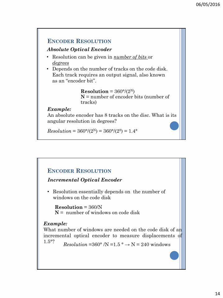
ENCODER RESOLUTION
• Resolution can be given in number of bits or
degrees
• Depends on the number of tracks on the code disk.
Each track requires an output signal, also known
as an “encoder bit”.
Absolute Optical Encoder
Resolution = 360°/(2N)N = number of encoder bits (number of tracks)
Example:
An absolute encoder has 8 tracks on the disc. What is its
angular resolution in degrees?
Resolution = 360°/(2N) = 360°/(28) = 1.4°
ENCODER RESOLUTION
• Resolution essentially depends on the number of
windows on the code disk
Incremental Optical Encoder
Resolution = 360/NN = number of windows on code disk
Example:
What number of windows are needed on the code disk of an
incremental optical encoder to measure displacements of
1.5°?Resolution =360° /N =1.5 ° → N = 240 windows
06/05/2016
15
Example:
Consider an incremental encoder that produces 2500-
pulses/revolution. Assume that the photo detectors in the decoder
circuit can handle signals up to 1 MHz frequency.
Determine the maximum shaft speed (RPM) the encoder
and decoder circuit can handle.
𝑤𝑚𝑎𝑥 =1,000,000 𝑝𝑢𝑙𝑠𝑒/𝑠𝑒𝑐
2,500 𝑝𝑢𝑙𝑠𝑒/𝑟𝑒𝑣= 400
𝑟𝑒𝑣
𝑠𝑒𝑐= 24,000 𝑅𝑃𝑀
LINEAR VARIABLE
DIFFERENTIAL TRANSFOERMERS
06/05/2016
16
WHAT IS A LVDT?
Linear variable differential transformer
Electromechanical transducer measuring linear
displacement
WHAT IS A LVDT?
Primary coil
Energized with constant A/C
Two identical secondary
coils
Symmetrically distributed
Connected in opposition
Ferromagnetic core
06/05/2016
17
HOW LVDT WORKS
If core is centered
between S1 and S2
Equal flux from each
secondary coil
Voltage E1 = E2
HOW LVDT WORKS
If core is closer to S1
Greater flux at S1
Voltage E1 increases,
Voltage E2 decreases
Eout=E1 – E2
06/05/2016
18
HOW LVDT WORKS
If core is closer to S2
Greater flux at S2
Voltage E2 increases,
Voltage E1 decreases
Eout=E2 – E1
HOW LVDT WORKS
06/05/2016
19
LVDT PROPERTIES
Friction-free operation
Unlimited mechanical life
Infinite resolution
Separable coil and core
Environmentally robust
Fast dynamic response
Absolute output
LVDT SUPPORT ELECTRONICS
LVDT signal conditioning equipment
Supply excitation power for the LVDT
Typically 3 Vrms at 3 kHz
Convert low level A/C output to high level DC signals
Gives directional information based on phase shift
06/05/2016
20
TYPES OF LVDTS
DC LVDT
Signal conditioning equipment built in
Pre-calibrated analog and/or digital output
Lower overall system cost
AC LVDT
Wide operating environments
Shock and vibration
Temperature
Smaller package size
TYPES OF LVDTS
SEPARATE CORE• Core is completely separable from the
transducer body• Well-suited for short-range (1 to 50mm),
high speed applications (high-frequency vibration)
GUIDED CORE• Core is restrained and guided by a low-
friction assembly• Both static and dynamic applications• working range (up to 500mm)
SPRING-LOADED• Core is restrained and guided by a low-
friction assembly• Internal spring to continuously push
the core to its fullest possible extension• Best suited for static or slow-moving
applications• Lower range than guided core(10 to
70mm)
06/05/2016
21
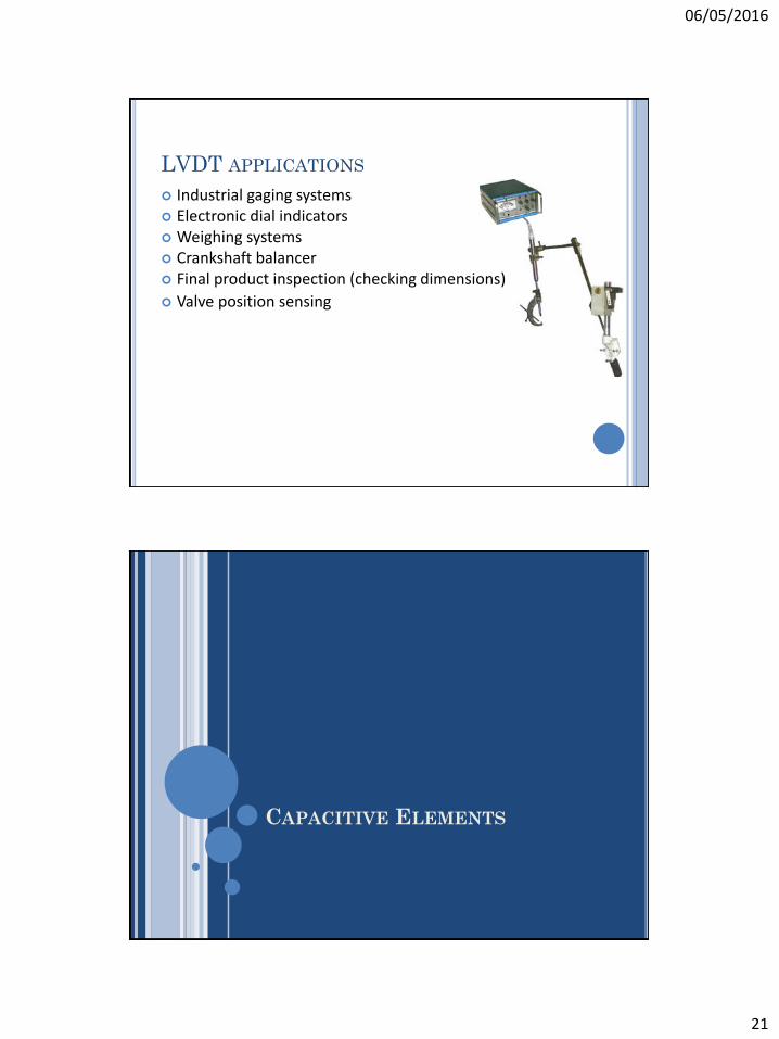
LVDT APPLICATIONS
Industrial gaging systems Electronic dial indicators Weighing systems Crankshaft balancer Final product inspection (checking dimensions)
Valve position sensing
CAPACITIVE ELEMENTS
06/05/2016
22
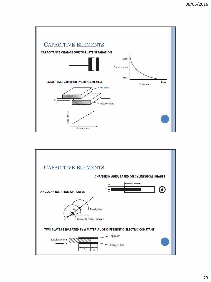
CAPACITIVE ELEMENTS
Capacitance transducers apply the principle of
capacitance variation between a set of plate
assemblies.
Capacitance is a function of the effective area of the
conductors, the separation between the conductors,
and the dielectric strength of the material.
A change in capacitance can be brought about by
varying any one of the three parameters.
Changing the distance between the two parallel
electrodes.
Changing the dielectric constant, permittivity, of
dielectric medium .
Changing the area of the electrodes, A.
CAPACITIVE ELEMENTS
06/05/2016
23
CAPACITIVE ELEMENTS
CAPACITIVE ELEMENTS
06/05/2016
24
ANGULAR VELOCITY SENSORS
ANGULAR VELOCITY SENSORS
Angular velocity sensors, or tachometers, are devices
that give an output proportional to angular velocity.
These sensors find wide application in motor-speed
control systems.
06/05/2016
25
TACHOMETERS
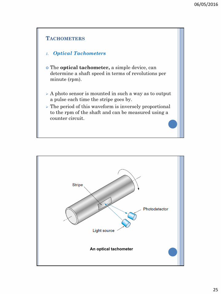
1. Optical Tachometers
The optical tachometer, a simple device, can
determine a shaft speed in terms of revolutions per
minute (rpm).
A photo sensor is mounted in such a way as to output
a pulse each time the stripe goes by.
The period of this waveform is inversely proportional
to the rpm of the shaft and can be measured using a
counter circuit.
An optical tachometer
06/05/2016
26
2. Toothed-Rotor Tachometers
A toothed-rotor tachometer consists of a stationary sensor and a rotating, toothed, iron-based wheel.
The toothed wheel (which looks like a big gear) can be built into the part to be measured.
The sensor generates a pulse each time a tooth passes by.
The angular velocity of the wheel is proportional to the frequency of the pulses.
There are two kinds of toothed-rotor sensors in use.
Variable reluctance sensor
Hall-effect sensor
TACHOMETERS
A toothed-rotor tachometer.
06/05/2016
27
3. Direct Current Tachometers
A direct current tachometer is essentially a DC generator that produces a DC output voltage proportional to shaft velocity.
The output polarity is determined by the direction of rotation.
Examples
6.9
6.10
6.11
TACHOMETERS
DC tachometer.
06/05/2016
28
PROXIMITY SENSORS
PROXIMITY SENSORS
Limit Switches
A proximity sensor simply tells the controller
whether a moving part is at a certain place.
A limit switch is an example of a proximity sensor.
A limit switch is a mechanical push-button switch
that is mounted in such a way that it is actuated
when a mechanical part or lever arm gets to the end
of its intended travel.
For example, in an automatic garage-door opener, all
the controller needs to know is if the door is all the
way open or all the way closed.
06/05/2016
29
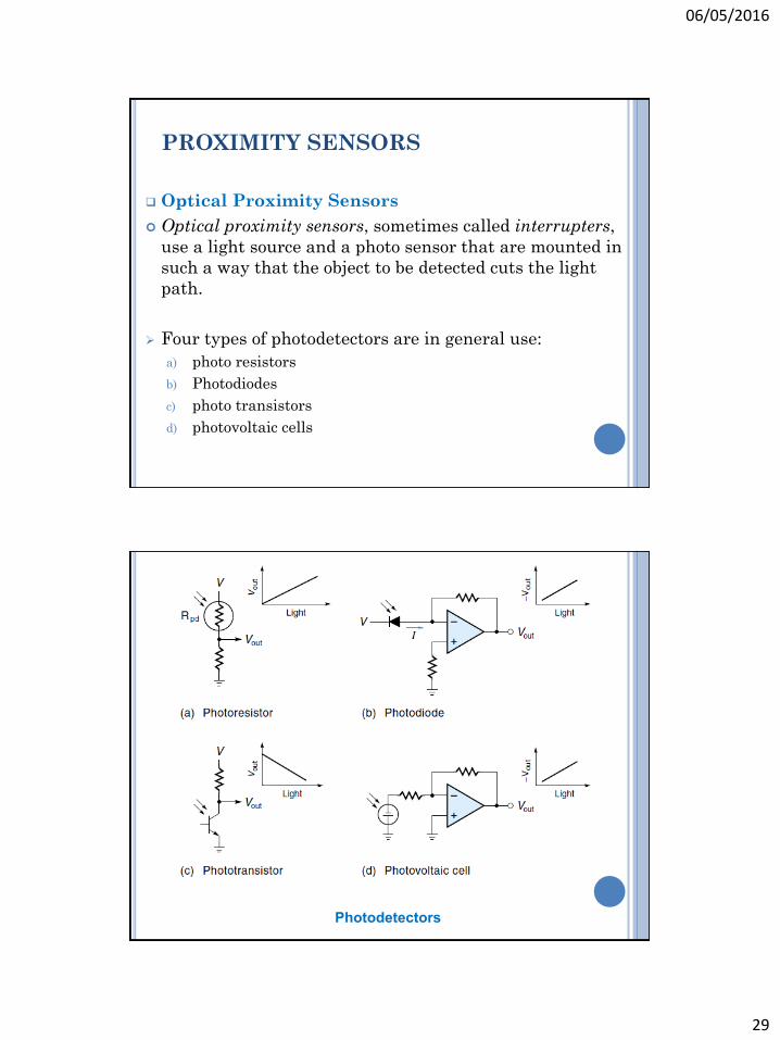
Optical Proximity Sensors
Optical proximity sensors, sometimes called interrupters,
use a light source and a photo sensor that are mounted in
such a way that the object to be detected cuts the light
path.
Four types of photodetectors are in general use:
a) photo resistors
b) Photodiodes
c) photo transistors
d) photovoltaic cells
PROXIMITY SENSORS
Photodetectors
06/05/2016
30
Hall-Effect Proximity Sensors
The Hall effect, as it is called, was originally used for wattmeters and gaussmeters; now it is used extensively for proximity sensors.
The Hall-effect sensor outputs a voltage when the magnetic field in which it finds itself increases.
When a magnetic field is brought near, the negative charges are deflected to one side producing a voltage. The relationship can be described in the following equation:
where
VH = Hall-effect voltage
K = constant (dependent on material)
I = current from an external source
B = magnetic flux density
D = thickness constant
PROXIMITY SENSORS
The operation of a Hall-effect sensor.
06/05/2016
31
LOAD SENSORS
Load sensors measure mechanical force.
The forces can be large or small.
for example, weighing heavy objects or detecting low-force
tactile pressures.
In most cases, it is the slight deformation caused by the
force that the sensor measures, not the force directly.
The ratio of the force to deformation is a constant for
each material, as defined by Hooke’s law:
F = KX
where
K = spring constant of the material
F = applied force
X = extension or compression as result of force
BONDED-WIRE STRAIN GAUGES
The bonded-wire strain gauge can be used to measure a
wide range of forces, from 10 lb to many tons.
It consists of a thin wire (0.001 in.) looped back-and-forth a
few times and cemented to a thin paper backing.
The principle of operation is as follows:
If the object is put under tension, the gauge will stretch and
elongate the wires. The wires not only get slightly longer but also
thinner. Both actions cause the total wire resistance to rise, as can
be seen from the basic resistance equation:
R = ρL/A
where
R = resistance of a length of wire (at 20°C)
ρ = resistivity (a constant dependent on the material)
L = length of wire
A = cross-sectional area of wire
06/05/2016
32
Strain gauges.
STRAIN-GAUGED ELEMENTS
Strain-gauge transducers are widely used for measuring strain, force, torque, pressure, and vibration.
Bonded strain gauges are made of metallic or semiconductor materials in the form of a wire gauge or thin metal foil.
When the gauges are bonded to the surface, they undergo the same strain as that of the member surface.
Strain gauges are sensitive devices and are used with an electronic measuring unit.
The strain gauge is normally made part of a Wheatstone bridge, so the change in its resistance due to strain either can be measured or used to produce an output, which can be displayed.
06/05/2016
33
STRAIN-GAUGED ELEMENTS
STRAIN-GAUGED ELEMENTS
Strains as low as a fraction of a micron can be measured using strain gauges.
For precise measurement, the strain gauges should have the following properties.
A high gauge factor increases the sensitivity and causes a larger change in resistance for a particular strain.
The gauge characteristics are chosen so that the variation in resistance is a linear function of strain.
If the gauges are used for dynamic measurements, the linearity should be maintained over the desired frequency range.
High resistance of the strain gauge minimizes the effect of resistance variation in the signal-processing circuitry.
Strain gauges have a low temperature coefficient and absence of the hysteresis effect.
06/05/2016
34
PRESSURE SENSORS
PRESSURE SENSORS
• Pressure is defined as the force per unit area that one
material exerts on another.
Pressure sensors usually consist of two parts:
The first converts pressure to a force or displacement,
The second converts the force or displacement to an
electrical signal.
Pressure measurements are made only for gases and
liquids.
Pressure measurements:
gauge pressure
differential pressure
absolute pressure
06/05/2016
35
1. Bourdon Tubes
A Bourdon tube is a short bent tube, closed at one end.
When the tube is pressurized, it tends to straighten out.
This motion is proportional to the applied pressure.
A position sensor such as a pot or LVDT can convert the
displacement into an electrical signal.
Bourdon-tube sensors are available in pressure ranges
from 30 to 100,000 psi.
PRESSURE SENSORS
Bourdon-tube sensors.
06/05/2016
36
2. Bellows
This sensor uses a small metal bellows to convert
pressure into linear motion.
As the pressure inside increases, the bellows
expand against the resistance of a spring.
This motion is detected with a position sensor
such as a pot.
PRESSURE SENSORS
Bellows pressure sensors.
06/05/2016
37
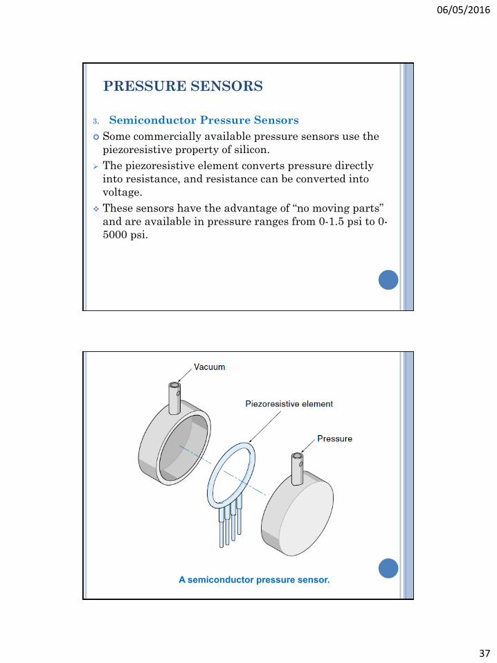
3. Semiconductor Pressure Sensors
Some commercially available pressure sensors use the
piezoresistive property of silicon.
The piezoresistive element converts pressure directly
into resistance, and resistance can be converted into
voltage.
These sensors have the advantage of “no moving parts”
and are available in pressure ranges from 0-1.5 psi to 0-
5000 psi.
PRESSURE SENSORS
A semiconductor pressure sensor.
06/05/2016
38
TEMPERATURE SENSORS
TEMPERATURE SENSORS
Temperature sensors give an output proportional to
temperature.
Most temperature sensors have a positive temperature
coefficient.
some sensors have a negative temperature coefficient.
Many control systems require temperature sensors, if
only to know how much to compensate other sensors
that are temperature-dependent.
06/05/2016
39
1. Bimetallic Temperature Sensors
The bimetallic temperature sensor consists of a
bimetallic strip wound into a spiral.
The bimetallic strip is a laminate of two metals with
different coefficients of thermal expansion.
As the temperature rises, the metal on the inside
expands more than the metal on the outside, and the
spiral tends to straighten out.
TEMPERATURE SENSORS
A bimetallic thermal sensor controlling a mercury switch
(shown in “cold” state).
06/05/2016
40
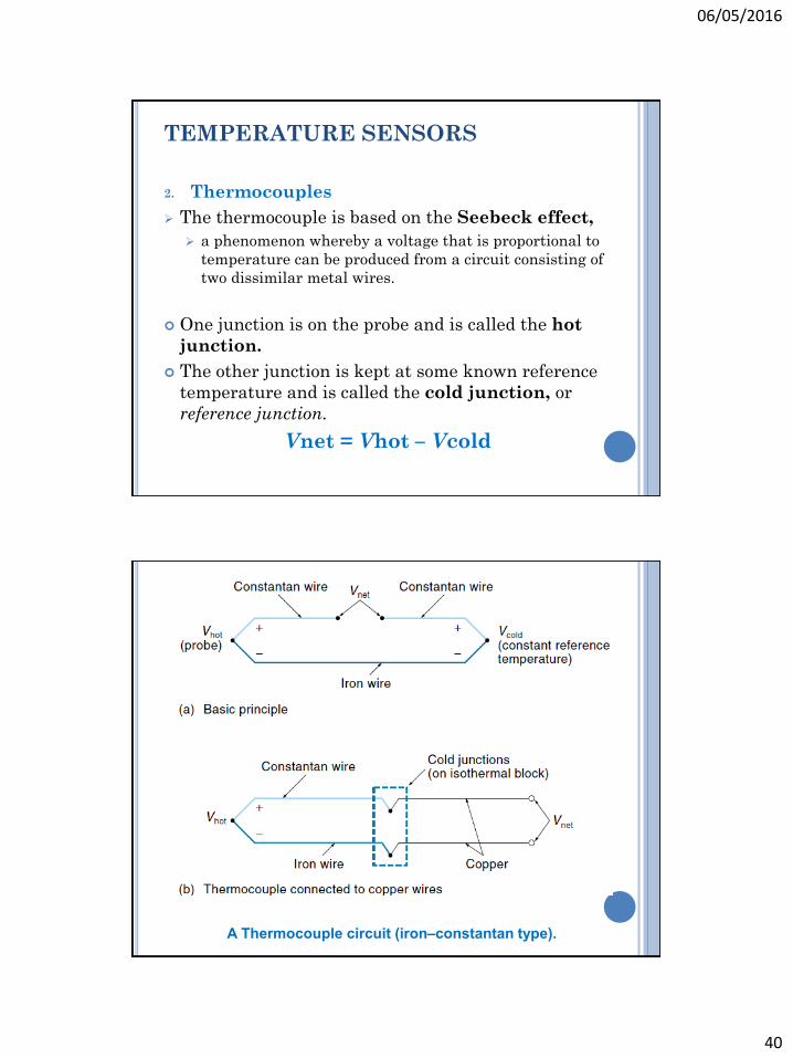
2. Thermocouples
The thermocouple is based on the Seebeck effect,
a phenomenon whereby a voltage that is proportional to
temperature can be produced from a circuit consisting of
two dissimilar metal wires.
One junction is on the probe and is called the hot
junction.
The other junction is kept at some known reference
temperature and is called the cold junction, or
reference junction.
Vnet = Vhot – Vcold
TEMPERATURE SENSORS
A Thermocouple circuit (iron–constantan type).
06/05/2016
41
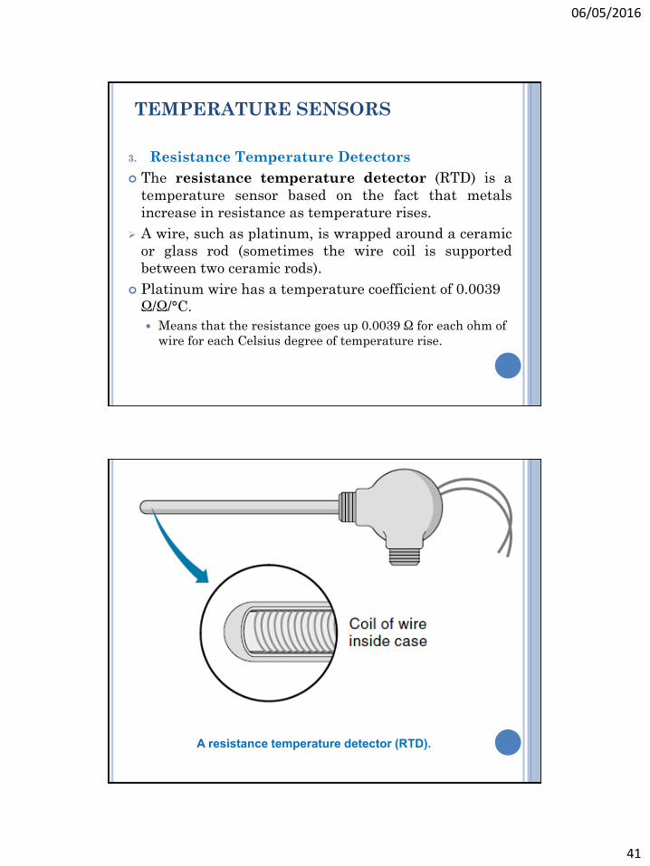
3. Resistance Temperature Detectors
The resistance temperature detector (RTD) is a
temperature sensor based on the fact that metals
increase in resistance as temperature rises.
A wire, such as platinum, is wrapped around a ceramic
or glass rod (sometimes the wire coil is supported
between two ceramic rods).
Platinum wire has a temperature coefficient of 0.0039
Ω/Ω/°C.
Means that the resistance goes up 0.0039 Ω for each ohm of
wire for each Celsius degree of temperature rise.
TEMPERATURE SENSORS
A resistance temperature detector (RTD).
06/05/2016
42
4. Thermistors
A thermistor is a two-terminal device that changes
resistance with temperature.
Thermistors are made of oxide-based semiconductor
materials and come in a variety of sizes and shapes.
Thermistors are nonlinear; therefore, they are not
usually used to get an accurate temperature reading but
to indicate temperature changes.
Thermistors come in a wide range of resistances, from a
few ohms to 1 MΩ, selection of which depends on the
temperature range of interest
TEMPERATURE SENSORS
A thermistor.
06/05/2016
43
5. Integrated-Circuit Temperature Sensors
Integrated-circuit temperature sensors come in various
configurations. A common example is the LM34 and
LM35 series.
The LM34 produces an output voltage that is proportional to
Fahrenheit temperature
The LM35 produces an output that is proportional to Celsius
temperature.
The output voltage of the LM35 is directly proportional
to °C, that is,
Vout = 10 mV/°C
Examples: 6.12 – 6.16
TEMPERATURE SENSORS
FLOW SENSORS
06/05/2016
44
FLOW SENSORS
Flow sensors measure the quantity of fluid material
passing by a point in a certain time.
1. Pressure-Based Flow Sensors
This group of flow sensors is based on the fact that
pressure in a moving fluid is proportional to the flow.
The pressure is detected with a pressure sensor; based
on the physical dimensions of the system, the flow can
be calculated. They are;
a. orifice plate
b. Venturi
c. pitot tube
PRESSURE-BASED FLOW SENSORS
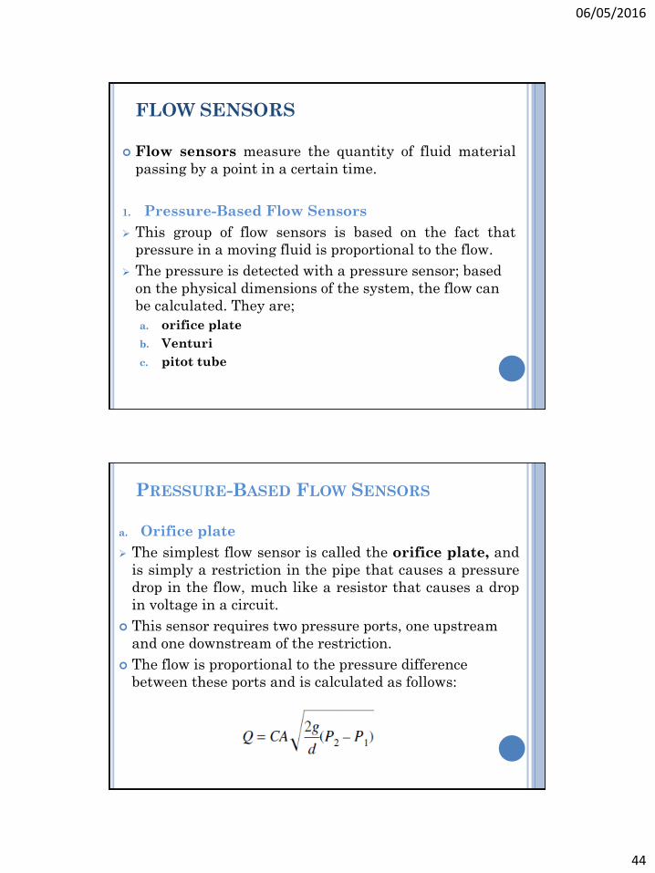
a. Orifice plate
The simplest flow sensor is called the orifice plate, and
is simply a restriction in the pipe that causes a pressure
drop in the flow, much like a resistor that causes a drop
in voltage in a circuit.
This sensor requires two pressure ports, one upstream
and one downstream of the restriction.
The flow is proportional to the pressure difference
between these ports and is calculated as follows:
06/05/2016
45
a. Orifice plate
where
Q = flow (in3)
C = coefficient of discharge (approximately 0.63 for water if the orifice
hole is at least half the pipe size)
A = area of the orifice hole (in2)
d = weight density of the fluid (lb/in3)
P2 – P1 = pressure difference (psi)
g = gravity (384 in./s2)
PRESSURE-BASED FLOW SENSORS
An orifice plate.
06/05/2016
46
b. Venturi
A venturi is a gradual restriction in the pipe that
causes the fluid velocity to increase in the restricted
area.
To create the pressure difference.
The flow is proportional to the difference in pressure
between P2 and P1.
The venturi flow sensor tends to keep the flow more
laminar (smooth), but both the orifice plate and the
venturi cause pressure drops in the pipe, which may be
objectionable.
PRESSURE-BASED FLOW SENSORS
A venturi flow sensor.
06/05/2016
47
c. pitot tube
The pitot tube is a small open tube that faces into the
flow.
A pressure-based flow sensor that causes minimum
restriction.
The probe actually consists of two tubes: One faces into
the flow and reports the impact pressure (often called
the velocity head), and one opens perpendicularly to the
flow and reports the static pressure.
The impact pressure is always greater than the static
pressure.
And the difference between these two pressures is
proportional to velocity and hence to flow.
PRESSURE-BASED FLOW SENSORS
A pitot tube.
06/05/2016
48
TURBINE FLOW SENSORS
Turbine Flow Sensors
Turbine, or spin-type, flow sensors (also called
flowmeters), employ a paddle wheel or propeller placed
in the line of flow.
The rotational velocity of the wheel is directly
proportional to flow velocity.
A small magnet is attached to one of the blades, and a
Hall-effect sensor is mounted in the housing.
The Hall sensor gives a pulse for each revolution of the
blades.
Magnetic Flowmeters
If a liquid is even slightly conductive (and many are), a
magnetic flowmeter can be used.
The magnetic flowmeter has no moving parts and
presents no obstruction to the flow.
A nonconducting section of pipe is placed in a magnetic
field.
The moving fluid in the pipe is like the moving conductor
in a generator—it produces a voltage.
The voltage, which is proportional to the fluid velocity, is
detected from electrodes placed in the sides of the pipe.
TURBINE FLOW SENSORS
06/05/2016
49
A magnetic flowmeter.
LIQUID LEVEL SENSORS
06/05/2016
50
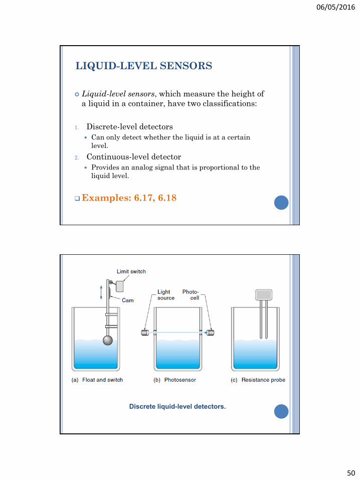
LIQUID-LEVEL SENSORS
Liquid-level sensors, which measure the height of
a liquid in a container, have two classifications:
1. Discrete-level detectors
Can only detect whether the liquid is at a certain
level.
2. Continuous-level detector
Provides an analog signal that is proportional to the
liquid level.
Examples: 6.17, 6.18
Discrete liquid-level detectors.
06/05/2016
51
Continuous-level detection methods.
06/05/2016
52
VISION SENSORS
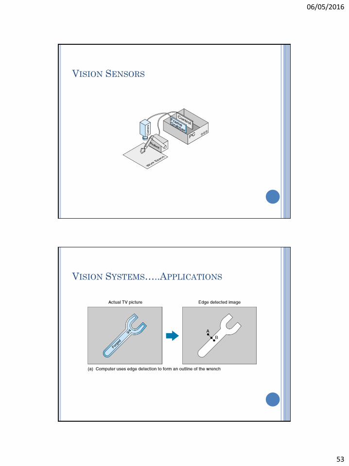
VISION SENSORS
A vision sensor is a camera connected to a computer.
Machine vision is being used to perform inspections
and to guide machine operations. For example, a
system might use machine vision to determine whether
parts had been made or assembled properly.
Alternatively, a vision system might be used to provide
guidance to a pick-and-place robot for doing such
things as unloading boxes from a pallet or inserting
components in a circuit board.
Vision systems require computing power to process
thousands of pixels of information continuously in
order to arrive at a go/no-go decision about what is