Multimedia signal processing, or media processing [1], is the processing of digital multimedia informationin a programmable processor. Digital multimedia information includes visual information like images,video, graphics, and animation, audio information like voice and music, and textual information likekeyboard text and handwriting. With general-purpose computers processing more multimedia informa-tion, multimedia instructions for efficient media processing have been defined for the instruction setarchitectures (ISAs) of microprocessors. Meanwhile, digital processing of video and audio data in consumerproducts has also resulted in more sophisticated multimedia processors. Traditional digital signal processors(DSPs) in music players and recorders and mobile telephones are becoming increasingly sophisticated asthey process multiple forms of multimedia data, rather than just audio signals. Video processors fortelevisions and video recorders have become more versatile as they have to take into account high-fidelityaudio processing and real-time three-dimensional (3-D) graphics animations. This has led to the design
of more versatile media processors, which combine the capabilities of DSPs for efficient audio and signalprocessing, video processors for efficient video processing, graphics processors for efficient 2-D and 3-Dgraphics processing, and general-purpose processors for efficient and flexible programming. The functionsperformed by microprocessors and media processors may eventually converge. In this chapter, some of thekey innovations in multimedia instructions added to microprocessor ISAs are described, which haveallowed high-fidelity multimedia to be processed in real-time on ubiquitous desktop and notebook com-puters. Many of these features have also been adopted in modern media processors and DSPs.
Subword Parallelism
Workload characterization studies on multimedia applications show that media applications have hugeamounts of data parallelism and operate on lower-precision data types. A pixel-oriented application, forexample, rarely needs to process data that is wider than 16 bits. This translates into low computationalefficiency on general-purpose processors where the register and datapath sizes are typically 32 or 64 bits,called the width of a word. Efficient processing of low-precision data types in parallel becomes a basicrequirement for improved multimedia performance. This is achieved by partitioning a word into multiple
subwords
, each subword representing a lower-precision datum. A
packed data type
will be defined as datathat consists of multiple subwords packed together. These subwords can be processed in parallel using asingle instruction, called a
subword-parallel
instruction, a
packed
instruction, or a
microSIMD
instruction.SIMD stands for “single instruction multiple data,” a term coined by Flynn [2] for describing very largeparallel machines with many data processors, where the same instruction issued from a single controlprocessor operates in parallel on data elements in the parallel data processors. Lee [3] coined the termmicroSIMD architecture to describe an ISA—where a single instruction operates in parallel on multiplesubwords within a single processor.
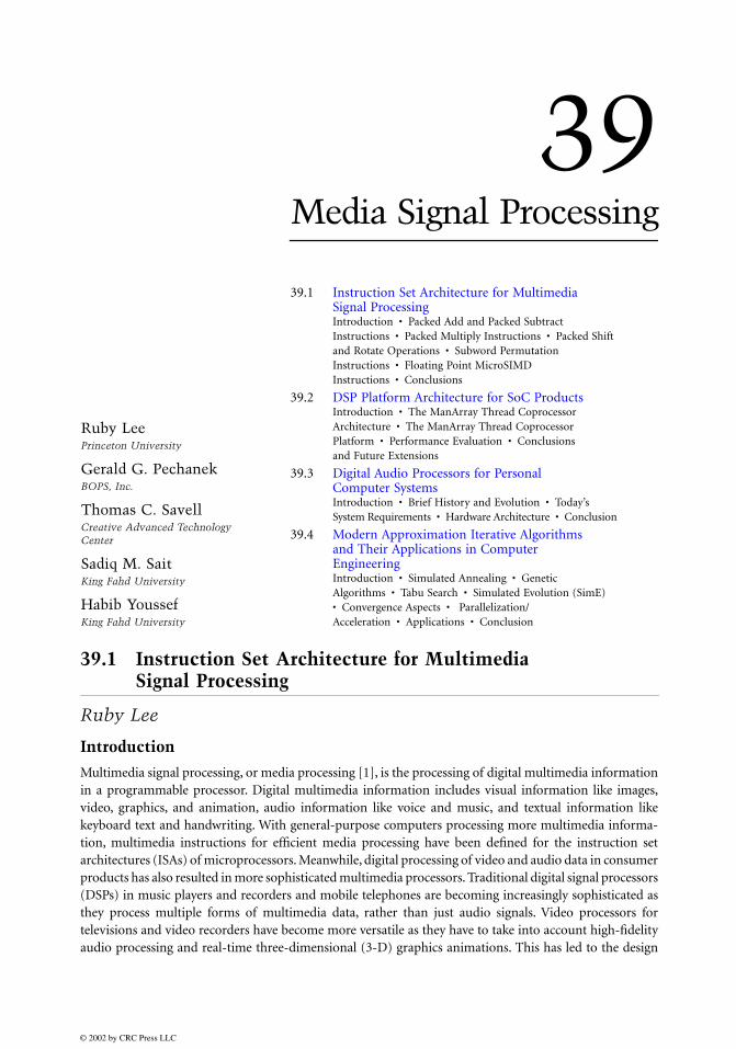
Figure 39.1 shows a 32-bit integer register that is made up of four 8-bit subwords. The subwords in theregister can be pixel values from a grayscale image. In this case, the register is holding four pixels withvalues 0xFF, 0x0F, 0xF0, and 0x00. The same 32-bit register can also be interpreted as two 16-bit subwords,in which case, these subwords would be 0xFF0F and 0xF000. The subword boundaries do not correspondto a physical boundary in the register file; they are merely how the bits in the word are interpreted by theprogram. If we have 64-bit registers, the most useful subword sizes will be 8-, 16-, or 32-bit words. A singleregister can then accommodate 8, 4, or 2 of these different sized subwords, respectively.
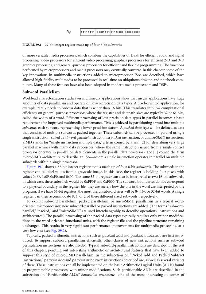
To exploit subword parallelism, packed parallelism, or microSIMD parallelism in a typical word-oriented microprocessor, new subword-parallel or packed instructions are added. (The terms “subword-parallel,” “packed,” and “microSIMD” are used interchangeably to describe operations, instructions andarchitectures.) The parallel processing of the packed data types typically requires only minor modifica-tions to the word-oriented functional units, with the register file and the pipeline structure remainingunchanged. This results in very significant performance improvements for multimedia processing, at avery low cost (see Fig. 39.2).
Typically, packed arithmetic instructions such as
packed
add
and
packed
subtract
are first intro-duced. To support subword parallelism efficiently, other classes of new instructions such as subwordpermutation instructions are also needed. Typical subword-parallel instructions are described in the restof this chapter, pointing out interesting arithmetic or architectural features that have been added tosupport this style of microSIMD parallelism. In the subsection on “Packed Add and Packed SubtractInstructions,”
packed
add
and
packed
subtract
instructions described are, as well as several variantsof these. These instructions can all be implemented on the basic Arithmetic Logical Units (ALUs) foundin programmable processors, with minor modifications. Such partitionable ALUs are described in thesubsection on “Partitionable ALUs.”
Saturation arithmetic
—one of the most interesting outcomes of
FIGURE 39.1
32-bit integer register made up of four 8-bit subwords.
subword-parallel additions—for efficiently handling overflows and performing in-line conditional oper-ations is also described. A variant of packed addition is the
packed
average
instruction, where unbiasedrounding is an interesting associated feature. Another class of packed instructions that can use the ALUis the
parallel
compare
instruction where the results are the outcomes of the subword comparisons.The subsection on “Packed Multiply Instruction” describes how packed integer multiplication is handled.
Also described are different approaches to solving the problem of the products being twice as large as thesubword operands that are multiplied in parallel. Although subword-parallel multiplication instructionsgenerally require the introduction of new integer multiplication functional units to a microprocessor, thespecial case of multiplication by constants, which can be achieved very efficiently with
packed
shift
andadd
instructions that can be implemented on an ALU with a small preshifter, is described.The subsection on “Packed Shift and Rotate Operations” describes
packed
shift
and
packedrotate
instructions, which perform a superset of the functions of a typical shifter found in micropro-cessors, in parallel, on packed subwords.
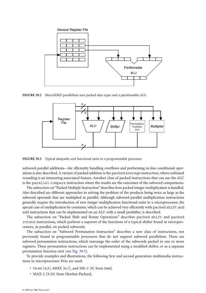
The subsection on “Subword Permutation Instruction” describes a new class of instructions, notpreviously found in programmable processors that do not support subword parallelism. These aresubword permutation instructions, which rearrange the order of the subwords packed in one or moreregisters. These permutation instructions can be implemented using a modified shifter, or as a separatepermutation function unit (see Fig. 39.3).
To provide examples and illustrations, the following first and second generation multimedia instruc-tions in microprocessor ISAs are used:
• IA-64 [4,5], MMX [6,7], and SSE-2 [8] from Intel,
• MAX-2 [9,10] from Hewlett-Packard,
FIGURE 39.2
MicroSIMD parallelism uses packed data types and a partitionable ALU.
FIGURE 39.3
Typical datapaths and functional units in a programmable processor.
The first generation multimedia instructions focused on subword parallelism in the integer domain.These are described and compared in [14]. The first set of multimedia extensions targeted at general-purpose multimedia acceleration, rather than just graphics acceleration, was MAX-1, introduced withthe PA-7100LC processor in January 1994 [15,16] by Hewlett-Packard. MAX-1, an acronym for “multi-media acceleration extensions,” is a minimalist set of multimedia instructions for the 32-bit PA-RISCprocessor [17]. An application that clearly illustrated the superior performance of MAX-1 was MPEG-1video and audio decoding with software, at real-time rates of 30 frames per second [18]. For the firsttime, this performance was made possible using software on a general-purpose processor in a low-enddesktop computer. Until then, such high-fidelity, real-time video decompression performance was notachievable without using specialized hardware. MAX-1 also accelerated pixel processing in graphicsrendering and image processing, and 16-bit audio processing.
Next, Sun introduced VIS [19], which was an extension for the UltraSparc processors. VIS was a muchlarger set of multimedia instructions. In addition to packed arithmetic operations, VIS provided veryspecialized instructions for accessing visual data, stored in predetermined ways in memory.
Intel introduced MMX [6,7] multimedia extensions in the dominant Pentium microprocessors inJanuary 1997, which immediately legitimized the valuable contribution of multimedia instructions forubiquitous multimedia applications.
MAX-2 [9] was Hewlett-Packard’s multimedia extension for its 64-bit PA-RISC 2.0 processors [10].Although designed simultaneously with MAX-1, it was only introduced in 1996, with the PA-RISC 2.0architecture. The subword permutation instructions introduced with MAX-2 were useful only with theincreased subword parallelism in 64-bit registers. Like MAX-1, MAX-2 was also a minimalist set ofgeneral-purpose media acceleration primitives.
MIPS also described MDMX multimedia extensions and Alpha described a very small set of MVImultimedia instructions for video compression.
The second generation multimedia instructions initially focused on subword parallelism on the floating-point (FP) side for accelerating graphics geometry computations and high-fidelity audio processing. Bothof these multimedia applications use single-precision, floating-point numbers for increased range andaccuracy, rather than 8-bit or 16-bit integers. These multimedia ISAs include SSE and SSE-2 [8] from Inteland 3DNow! [11,12] from AMD. Finally, the PowerPC’s AltiVec [13] and the Intel-HP IA-64 [4,5] multi-media instruction sets are comprehensive integer and floating-point multimedia instructions. Today, everymicroprocessor ISA and most media and DSP ISAs include subword-parallel multimedia instructions.
Packed Add and Packed Subtract Instructions
Packed
add
and
packed
subtract
instructions are similar to ordinary
add
and
subtract
instruc-tions, except that the operations are performed in parallel on the subwords of two source registers.
Add
(nonpacked) and
packed
add
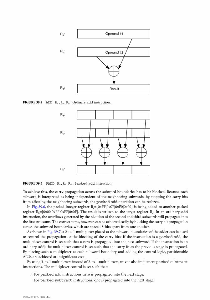
operations are shown in Figs. 39.4 and 39.5, respectively. The
packedadd
in Fig. 39.5 uses source registers with four subwords each. The corresponding subwords from thetwo source registers are summed up, and the four sums are written to the target register. A
packedsubtract
operation operates similarly.
Partitionable ALUs
Very minor modifications to the underlying functional units are needed to implement
packed
add
and
packed
subtract
instructions. Assume that we have an ALU with 32-bit integer registers, and we wantto extend this ALU to perform a
packed
add
that will operate on four 8-bit subwords in parallel.
1
3DNow! may be considered as having two versions. In June 2000, 25 new instructions were added to the original3DNow! specification. In this text, this extended 3DNow! architecture will be considered.
To achieve this, the carry propagation across the subword boundaries has to be blocked. Because eachsubword is interpreted as being independent of the neighboring subwords, by stopping the carry bitsfrom affecting the neighboring subwords, the
packed
add
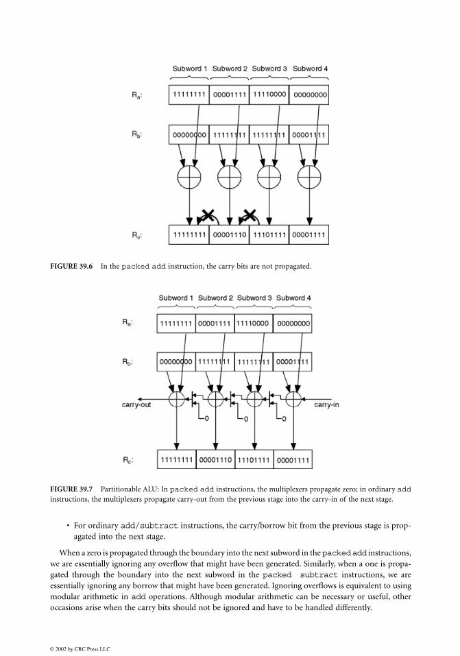
operation can be realized. In Fig. 39.6, the packed integer register R
a
=
[0xFF|0x0F|0xF0|0x00] is being added to another packedregister R
b
=
[0x00|0xFF|0xFF|0x0F]. The result is written to the target register R
c
. In an ordinary
add
instruction, the overflows generated by the addition of the second and third subwords will propagate intothe first two sums. The correct sums, however, can be achieved easily by blocking the carry bit propagationacross the subword boundaries, which are spaced 8-bits apart from one another.
As shown in Fig. 39.7, a 2-to-1 multiplexer placed at the subword boundaries of the adder can be usedto control the propagation or the blocking of the carry bits. If the instruction is a
packed
add
, themultiplexer control is set such that a zero is propagated into the next subword. If the instruction is anordinary
add
, the multiplexer control is set such that the carry from the previous stage is propagated.By placing such a multiplexer at each subword boundary and adding the control logic, partitionableALUs are achieved at insignificant cost.
By using 3-to-1 multiplexers instead of 2-to-1 multiplexers, we can also implement
packed
subtract
instructions. The multiplexer control is set such that:
• For
packed
add
instructions, zero is propagated into the next stage.
• For
packed
subtract
instructions, one is propagated into the next stage.
instructions, the carry/borrow bit from the previous stage is prop-agated into the next stage.
When a zero is propagated through the boundary into the next subword in the
packed
add
instructions,we are essentially ignoring any overflow that might have been generated. Similarly, when a one is propa-gated through the boundary into the next subword in the
packed subtract
instructions, we areessentially ignoring any borrow that might have been generated. Ignoring overflows is equivalent to usingmodular arithmetic in
add
operations. Although modular arithmetic can be necessary or useful, otheroccasions arise when the carry bits should not be ignored and have to be handled differently.
FIGURE 39.6
In the
packed
add
instruction, the carry bits are not propagated.
FIGURE 39.7
Partitionable ALU: In
packed
add instructions, the multiplexers propagate zero; in ordinary addinstructions, the multiplexers propagate carry-out from the previous stage into the carry-in of the next stage.
Overflows in packed add/subtract instructions can be handled in the following ways:
• The overflow may be ignored (modular arithmetic).
• A flag bit may be set if at least one overflow is generated.
• Multiple flag bits (i.e., one flag bit for each addition operation on the subwords) may be set.
• A software overflow trap can be taken.
• Saturation arithmetic: the results are limited to a certain range. If the outcome of the operationfalls outside this range, the corresponding limiting value will be the result.
Most nonpacked integer add/subtract instructions choose to ignore overflows and perform mod-ular arithmetic. In modular arithmetic, the numbers wrap around from the largest representable numberto the smallest representable number. For example, in 8-bit modular arithmetic, the operation 254+2will give a result of 0. The expected result, 256, is larger than the largest representable number, which is255, and therefore is wrapped around to the smallest representable number, which is 0.
In multimedia applications, modular arithmetic frequently gives undesirable results. If the numbersin the previous example were pixel values in a grayscale image, by wrapping the values from 255 downto 0, white pixels would have converted into black ones. One solution to this problem is to use overflowtraps, which are implemented in software.
A flag bit is an indicator bit that is set or cleared depending on the outcome of a particular operation.In the context of this discussion, an overflow flag bit is an indicator that is set when an add instructiongenerates an overflow. Occasions arise where the use of the flag bits are desirable. Consider a loop thatiterates many times and in each iteration, executes many add instructions. In this case, it is not desirableto handle overflows (by taking overflow trap routines) as soon as they occur, because this would negativelyimpact the performance by interrupting the execution of the loop body. Instead, the overflow flag canbe set when the overflow occurs, and the program flow continues as if the overflow did not occur. Atthe end of each iteration, however, this overflow flag can be checked and the overflow trap can be executedif the flag turns out to be set. This way, the program flow would not be interrupted while the loop bodyexecutes.
An overflow trap can be used to saturate the results so that the aforementioned problems would notoccur. A result that is greater than the largest representable value is replaced by that largest value. Similarly,a result that is less than the smallest representable value is replaced by that smallest value. One problemwith this solution will be its negative effects to performance. An overflow trap is handled in software andmay take many clock cycles to resolve. This can be acceptable only if the overflows are infrequent. Fornonpacked add/subtract instructions, generation of an overflow on a 64-bit register by adding 8-bitquantities will be rare, so a software overflow trap will work well. This is not the case for packed arithmeticoperations. Causing an overflow in an 8-bit subword is much more likely than in a 64-bit register. Also,since a 64-bit register may hold eight 8-bit subwords, multiple overflows can occur in a single executioncycle. In this case, handling the overflows by software traps could easily negate any performance gainsfrom executing packed operations. The use of saturation arithmetic solves this problem.
Saturation Arithmetic
Saturation arithmetic implements in hardware the work done by the overflow trap described above. Theresults falling outside the allowed numeric ranges are saturated to the upper and lower limits by hardware.This can handle multiple parallel overflows efficiently, without operating system intervention. Two typesoverflows for arithmetic operations are:
• A positive overflow occurs when the result is larger than the largest value in the defined range forthat result
• A negative overflow occurs when the result is smaller than the smallest value in the defined rangefor that result
If saturation arithmetic is used in an operation, the result is clipped to the maximum value in itsdefined range if a positive overflow occurs, and to the minimum value in its defined range if a negativeoverflow occurs.
For a given instruction, multiple saturation options may exist, depending on whether the operandsand the result are treated as signed or unsigned integers. For an instruction that uses three registers (twofor source operands and one for the result), there can be eight different saturation options. Each one ofthe three registers can be treated as containing either a signed or an unsigned integer, which gives 23
possible combinations. Not all of the eight possible saturation options are equally useful. Only three ofthe eight possible saturation options are used in any of the multimedia ISAs surveyed:
a) sss (signed result–signed first operand–signed second operand): In this saturation option, theresult and the two operands are all treated as signed integers. The most significant bit is consideredthe sign bit. Considering n-bit subwords, the result and operands are defined in the range [−2n−1,2n−1 − 1]. If a positive overflow occurs, the result is saturated to 2n − 1. If a negative overflow occurs,the result is saturated to −2n−1. In an addition operation that uses the sss saturation option, sincethe operands are signed numbers, a positive overflow is possible only when both operands arepositive. Similarly, a negative overflow is possible only when both operands are negative.
b) uuu (unsigned result–unsigned first operand–unsigned second operand): In this saturation option,the result and the two operands are all treated as unsigned integers. Considering n-bit integersubwords, the result and the operands are defined in the range [0,2n − 1]. If a positive overflowoccurs, the result is saturated to 2n − 1. If a negative overflow occurs, the result is saturated tozero. In an addition operation that uses the uuu saturation option, since the operands are unsignednumbers, negative overflow is not a possibility; however, for a subtraction operation using theuuu saturation, negative overflow is possible, and any negative result will be clamped to zero asthe smallest value.
c) uus (unsigned result–unsigned first operand–signed second operand): In this saturation option,the result and the first operand are treated as unsigned numbers, and the second operand is treatedas a signed number. Although this may seem like an unusual option, it proves useful because itallows the addition of a signed increment to an unsigned pixel. It also allows negative numbersto be clipped to zero. Its implementation has logical symmetry to the sss case.
In addition to the efficient handling of overflows, saturation arithmetic also facilitates several otheruseful computations. For instance, saturation arithmetic can also be used to clip results to arbitrary max-imum or minimum values. Without saturation arithmetic, these operations could normally take up tofive instructions for each pair of subwords. That would include instructions to check for upper and lowerbounds and then to perform the clipping. Using saturation arithmetic, however, this effect can be achievedin as few as two instructions for all the pairs of packed subwords.
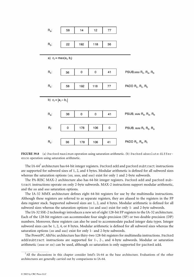
Saturation arithmetic can also be used for in-line conditional execution, reducing the need for con-ditional branches that can cause significant performance degradations in pipelined processors. Someexamples are the packed maximum and packed absolute difference operations shown inFigs. 39.8(a, b).
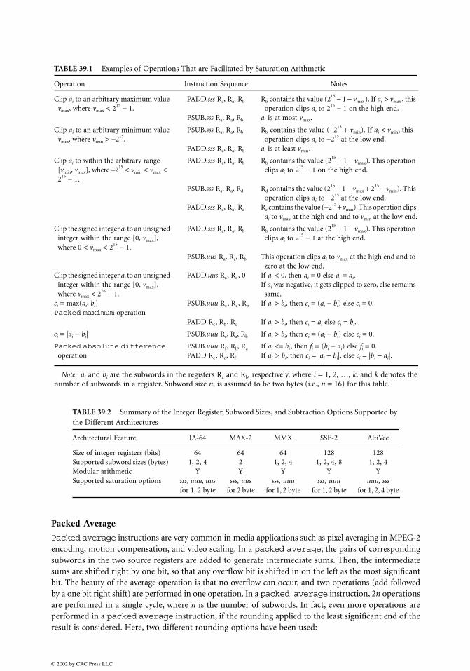
Table 39.1 contains examples of operations that can be performed using saturation arithmetic [15].All of the instructions in the table use three registers. The first register is the target register. The secondand the third registers hold the first and the second operands respectively. PADD and PSUB denotepacked add and packed subtract instructions. The three-letter field after the instruction mnemonicspecifies which saturation option is to be used. If this field is empty, modular arithmetic is assumed.All the examples in the table operate on 16-bit integer subwords.
Table 39.2 contains a summary of the register and subword sizes and the saturation options found indifferent multimedia ISAs. Table 39.3 is a summary of the packed add/subtract instructions inseveral multimedia ISAs. The first column contains descriptions of common packed instructions. Thesymbols ai and bi represent the corresponding subwords from the two source registers. The symbol ci
represents the corresponding subword in the target register.
The IA-642 architecture has 64-bit integer registers. Packed add and packed subtract instructionsare supported for subword sizes of 1, 2, and 4 bytes. Modular arithmetic is defined for all subword sizeswhereas the saturation options (sss, uuu, and uus) exist for only 1 and 2-byte subwords.
The PA-RISC MAX-2 architecture also has 64-bit integer registers. Packed add and packed sub-tract instructions operate on only 2-byte subwords. MAX-2 instructions support modular arithmetic,and the sss and uus saturation options.
The IA-32 MMX architecture defines eight 64-bit registers for use by the multimedia instructions.Although these registers are referred to as separate registers, they are aliased to the registers in the FPdata register stack. Supported subword sizes are 1, 2, and 4 bytes. Modular arithmetic is defined for allsubword sizes whereas the saturation options (sss and uus) exist for only 1- and 2-byte subwords.
The IA-32 SSE-2 technology introduces a new set of eight 128-bit FP registers to the IA-32 architecture.Each of the 128-bit registers can accommodate four single-precision (SP) or two double-precision (DP)numbers. Moreover, these registers can also be used to accommodate packed integer data types. Integersubword sizes can be 1, 2, 4, or 8 bytes. Modular arithmetic is defined for all subword sizes whereas thesaturation options (sss and uus) exist for only 1- and 2-byte subwords.
The PowerPC AltiVec architecture has thiry-two 128-bit registers for multimedia instructions. Packedadd/subtract instructions are supported for 1-, 2-, and 4-byte subwords. Modular or saturationarithmetic (uuu or sss) can be used, although sss saturation is only supported for packed add.
FIGURE 39.8 (a) Packed maximum operation using saturation arithmetic. (b) Packed absolute differ-ence operation using saturation arithmetic.
2All the discussions in this chapter consider Intel’s IA-64 as the base architecture. Evaluations of the otherarchitectures are generally carried out by comparisons to IA-64.
Packed average instructions are very common in media applications such as pixel averaging in MPEG-2encoding, motion compensation, and video scaling. In a packed average, the pairs of correspondingsubwords in the two source registers are added to generate intermediate sums. Then, the intermediatesums are shifted right by one bit, so that any overflow bit is shifted in on the left as the most significantbit. The beauty of the average operation is that no overflow can occur, and two operations (add followedby a one bit right shift) are performed in one operation. In a packed average instruction, 2n operationsare performed in a single cycle, where n is the number of subwords. In fact, even more operations areperformed in a packed average instruction, if the rounding applied to the least significant end of theresult is considered. Here, two different rounding options have been used:
TABLE 39.1 Examples of Operations That are Facilitated by Saturation Arithmetic
Operation Instruction Sequence Notes
Clip ai to an arbitrary maximum value vmax, where vmax < 215 − 1.
PADD.sss Ra, Ra, Rb
PSUB.sss Ra, Ra, Rb
Rb contains the value (215 − 1 − vmax). If ai > vmax, this operation clips ai to 215 − 1 on the high end.
ai is at most vmax.
Clip ai to an arbitrary minimum value vmin, where vmin > −215.
PSUB.sss Ra, Ra, Rb
PADD.sss Ra, Ra, Rb
Rb contains the value (−215 + vmin). If ai < vmin, this operation clips ai to −215 at the low end.
ai is at least vmin.
Clip ai to within the arbitrary range [vmin, vmax], where –215 < vmin < vmax < 215 − 1.
PADD.sss Ra, Ra, Rb
PSUB.sss Ra, Ra, Rd
PADD.sss Ra, Ra, Re
Rb contains the value (215 − 1 − vmax). This operation clips ai to 215 − 1 on the high end.
Rd contains the value (215 − 1 − vmax + 215 − vmin). This operation clips ai to −215 at the low end.
Re contains the value (−215 + vmin). This operation clips ai to vmax at the high end and to vmin at the low end.
Clip the signed integer ai to an unsigned integer within the range [0, vmax], where 0 < vmax < 215 − 1.
PADD.sss Ra, Ra, Rb
PSUB.uus Ra, Ra, Rb
Rb contains the value (215 − 1 − vmax). This operation clips ai to 215 − 1 at the high end.
This operation clips ai to vmax at the high end and to zero at the low end.
Clip the signed integer ai to an unsigned integer within the range [0, vmax], where vmax < 216 − 1.
PADD.uus Ra, Ra, 0 If ai < 0, then ai = 0 else ai = ai.If ai was negative, it gets clipped to zero, else remains
same.ci = max(ai, bi) PSUB.uuu Rc, Ra, Rb If ai > bi, then ci = (ai − bi) else ci = 0.Packed maximum operation
PADD Rc, Rb, Rc If ai > bi, then ci = ai else ci = bi.
ci = |ai − bi| PSUB.uuu Re, Ra, Rb If ai > bi, then ei = (ai − bi) else ei = 0.
Packed absolute difference operation
PSUB.uuu Rf, Rb, Ra
PADD Rc, Re, Rf
If ai <= bi , then fi = (bi − ai) else fi = 0.If ai > bi, then ci = |ai − bi|, else ci = |bi − ai|.
Note: ai and bi are the subwords in the registers Ra and Rb, respectively, where i = 1, 2, …, k, and k denotes thenumber of subwords in a register. Subword size n, is assumed to be two bytes (i.e., n = 16) for this table.
TABLE 39.2 Summary of the Integer Register, Subword Sizes, and Subtraction Options Supported by the Different Architectures
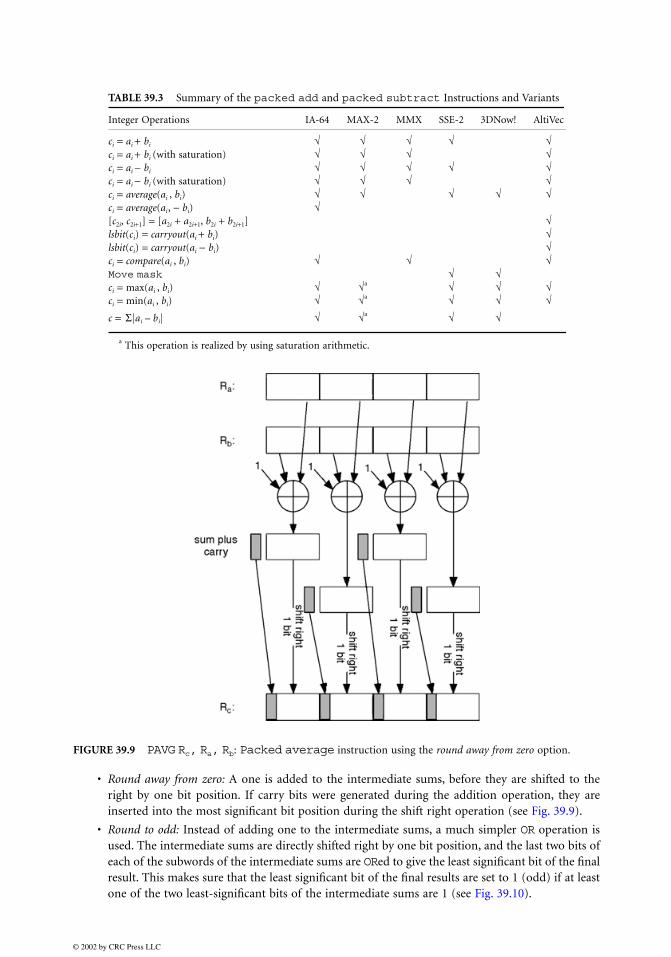
• Round away from zero: A one is added to the intermediate sums, before they are shifted to theright by one bit position. If carry bits were generated during the addition operation, they areinserted into the most significant bit position during the shift right operation (see Fig. 39.9).
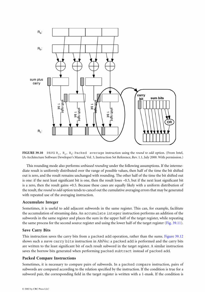
• Round to odd: Instead of adding one to the intermediate sums, a much simpler OR operation isused. The intermediate sums are directly shifted right by one bit position, and the last two bits ofeach of the subwords of the intermediate sums are ORed to give the least significant bit of the finalresult. This makes sure that the least significant bit of the final results are set to 1 (odd) if at leastone of the two least-significant bits of the intermediate sums are 1 (see Fig. 39.10).
TABLE 39.3 Summary of the packed add and packed subtract Instructions and Variants
This rounding mode also performs unbiased rounding under the following assumptions. If the interme-diate result is uniformly distributed over the range of possible values, then half of the time the bit shiftedout is zero, and the result remains unchanged with rounding. The other half of the time the bit shifted outis one: if the next least significant bit is one, then the result loses –0.5, but if the next least significant bitis a zero, then the result gains +0.5. Because these cases are equally likely with a uniform distribution ofthe result, the round to odd option tends to cancel out the cumulative averaging errors that may be generatedwith repeated use of the averaging instruction.
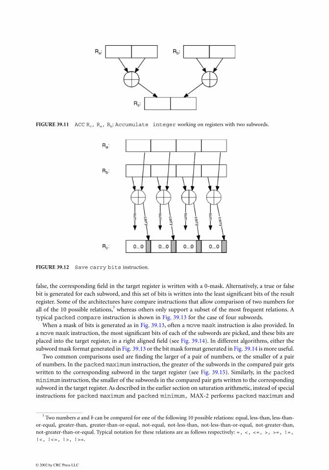
Accumulate Integer
Sometimes, it is useful to add adjacent subwords in the same register. This can, for example, facilitatethe accumulation of streaming data. An accumulate integer instruction performs an addition of thesubwords in the same register and places the sum in the upper half of the target register, while repeatingthe same process for the second source register and using the lower half of the target register (Fig. 39.11).
Save Carry Bits
This instruction saves the carry bits from a packed add operation, rather than the sums. Figure 39.12shows such a save carry bits instruction in AltiVec: a packed add is performed and the carry bitsare written to the least significant bit of each result subword in the target register. A similar instructionsaves the borrow bits generated when performing packed subtract instead of packed add.
Packed Compare Instructions
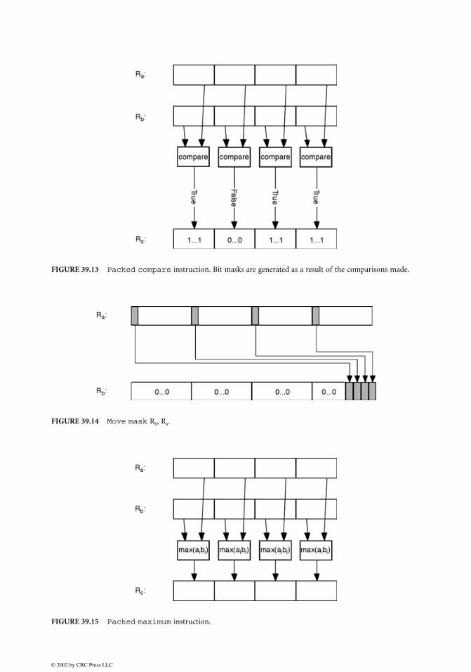
Sometimes, it is necessary to compare pairs of subwords. In a packed compare instruction, pairs ofsubwords are compared according to the relation specified by the instruction. If the condition is true for asubword pair, the corresponding field in the target register is written with a 1-mask. If the condition is
FIGURE 39.10 PAVG Rc, Ra, Rb: Packed average instruction using the round to odd option. (From Intel,IA-Architecture Software Developer’s Manual, Vol. 3, Instruction Set Reference, Rev. 1.1, July 2000. With permission.)
false, the corresponding field in the target register is written with a 0-mask. Alternatively, a true or falsebit is generated for each subword, and this set of bits is written into the least significant bits of the resultregister. Some of the architectures have compare instructions that allow comparison of two numbers forall of the 10 possible relations,3 whereas others only support a subset of the most frequent relations. Atypical packed compare instruction is shown in Fig. 39.13 for the case of four subwords.
When a mask of bits is generated as in Fig. 39.13, often a move mask instruction is also provided. Ina move mask instruction, the most significant bits of each of the subwords are picked, and these bits areplaced into the target register, in a right aligned field (see Fig. 39.14). In different algorithms, either thesubword mask format generated in Fig. 39.13 or the bit mask format generated in Fig. 39.14 is more useful.
Two common comparisons used are finding the larger of a pair of numbers, or the smaller of a pairof numbers. In the packed maximum instruction, the greater of the subwords in the compared pair getswritten to the corresponding subword in the target register (see Fig. 39.15). Similarly, in the packedminimum instruction, the smaller of the subwords in the compared pair gets written to the correspondingsubword in the target register. As described in the earlier section on saturation arithmetic, instead of specialinstructions for packed maximum and packed minimum, MAX-2 performs packed maximum and
FIGURE 39.11 ACC Rc, Ra, Rb: Accumulate integer working on registers with two subwords.
FIGURE 39.12 Save carry bits instruction.
3 Two numbers a and b can be compared for one of the following 10 possible relations: equal, less-than, less-than-or-equal, greater-than, greater-than-or-equal, not-equal, not-less-than, not-less-than-or-equal, not-greater-than,not-greater-than-or-equal. Typical notation for these relations are as follows respectively: =, <, <=, >, >=, !=,!<, !<=, !>, !>=.
packed minimum operations by using packed add and packed subtract instructions with satu-ration arithmetic (see Fig. 39.8). An ALU can be used to implement comparisons, maximum andminimum instructions with a subtraction operation; comparisons for equality or inequality is usuallydone with an exclusive-or operation, also available in most ALUs.
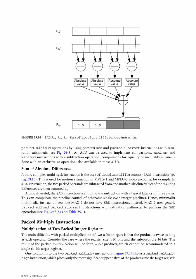
Sum of Absolute Differences
A more complex, multi-cycle instruction is the sum of absolute differences (SAD) instruction (seeFig. 39.16). This is used for motion estimation in MPEG-1 and MPEG-2 video encoding, for example. Ina SAD instruction, the two packed operands are subtracted from one another. Absolute values of the resultingdifferences are then summed up.
Although useful, the SAD instruction is a multi-cycle instruction with a typical latency of three cycles.This can complicate the pipeline control of otherwise single cycle integer pipelines. Hence, minimalistmultimedia instruction sets like MAX-2 do not have SAD instructions. Instead, MAX-2 uses genericpacked add and packed subtract instructions with saturation arithmetic to perform the SADoperation (see Fig. 39.8(b) and Table 39.1).
Packed Multiply Instructions
Multiplication of Two Packed Integer Registers
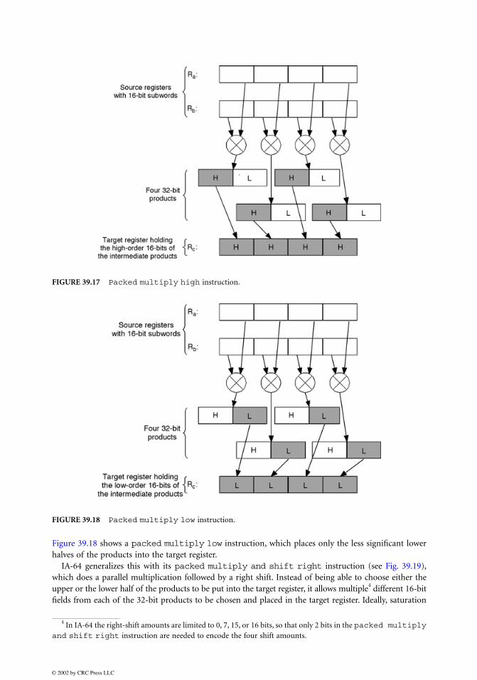
The main difficulty with packed multiplication of two n-bit integers is that the product is twice as longas each operand. Consider the case where the register size is 64 bits and the subwords are 16 bits. Theresult of the packed multiplication will be four 32-bit products, which cannot be accommodated in asingle 64-bit target register.
One solution is to use two packed multiply instructions. Figure 39.17 shows a packed multiplyhigh instruction, which places only the more significant upper halves of the products into the target register.
FIGURE 39.16 SAD Rc, Ra, Rb: Sum of absolute differences instruction.
Figure 39.18 shows a packed multiply low instruction, which places only the less significant lowerhalves of the products into the target register.
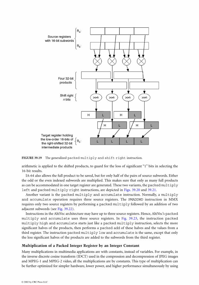
IA-64 generalizes this with its packed multiply and shift right instruction (see Fig. 39.19),which does a parallel multiplication followed by a right shift. Instead of being able to choose either theupper or the lower half of the products to be put into the target register, it allows multiple4 different 16-bitfields from each of the 32-bit products to be chosen and placed in the target register. Ideally, saturation
FIGURE 39.17 Packed multiply high instruction.
FIGURE 39.18 Packed multiply low instruction.
4 In IA-64 the right-shift amounts are limited to 0, 7, 15, or 16 bits, so that only 2 bits in the packed multiplyand shift right instruction are needed to encode the four shift amounts.
arithmetic is applied to the shifted products, to guard for the loss of significant “1” bits in selecting the16-bit results.
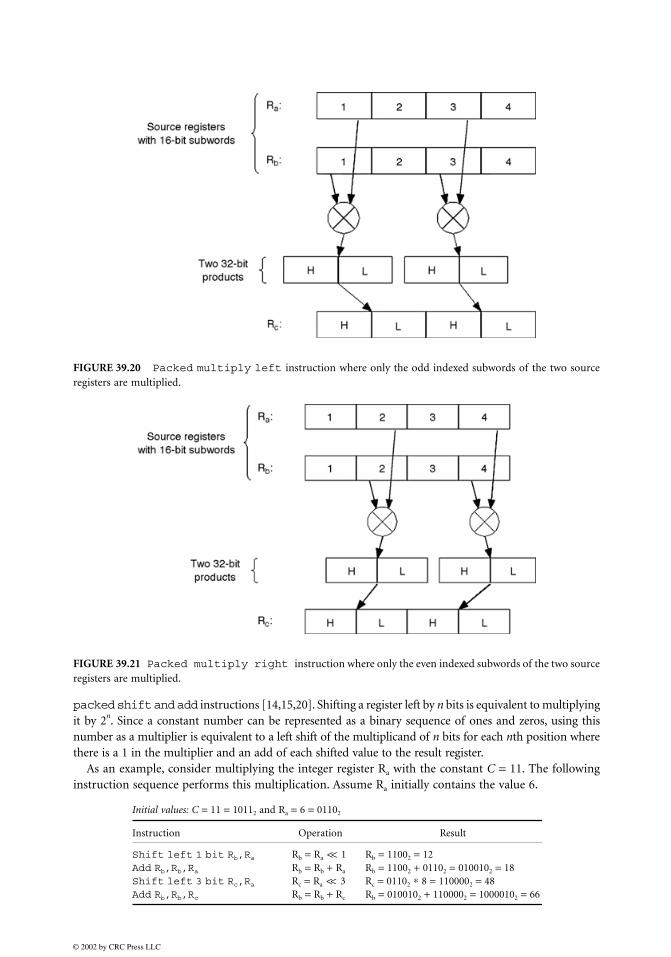
IA-64 also allows the full product to be saved, but for only half of the pairs of source subwords. Eitherthe odd or the even indexed subwords are multiplied. This makes sure that only as many full productsas can be accommodated in one target register are generated. These two variants, the packed multiplyleft and packed multiply right instructions, are depicted in Figs. 39.20 and 39.21.
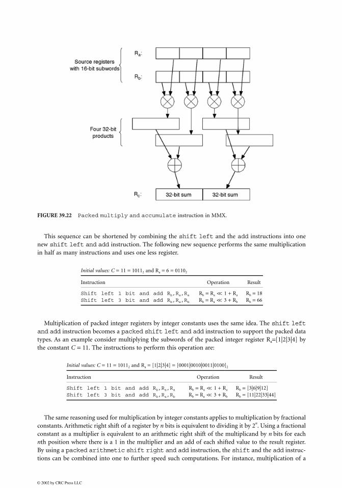
Another variant is the packed multiply and accumulate instruction. Normally, a multiplyand accumulate operation requires three source registers. The PMADDWD instruction in MMXrequires only two source registers by performing a packed multiply followed by an addition of twoadjacent subwords (see Fig. 39.22).
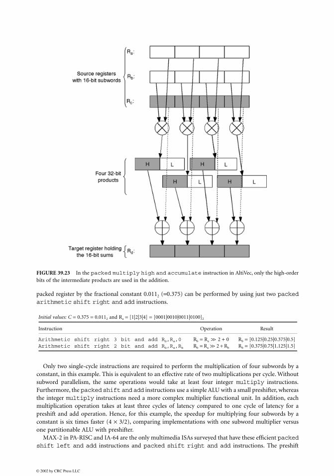
Instructions in the AltiVec architecture may have up to three source registers. Hence, AltiVec’s packedmultiply and accumulate uses three source registers. In Fig. 39.23, the instruction packedmultiply high and accumulate starts just like a packed multiply instruction, selects the moresignificant halves of the products, then performs a packed add of these halves and the values from athird register. The instruction packed multiply low and accumulate is the same, except that onlythe less significant halves of the products are added to the subwords from the third register.
Multiplication of a Packed Integer Register by an Integer Constant
Many multiplications in multimedia applications are with constants, instead of variables. For example, inthe inverse discrete cosine transform (IDCT) used in the compression and decompression of JPEG imagesand MPEG-1 and MPEG-2 video, all the multiplications are by constants. This type of multiplication canbe further optimized for simpler hardware, lower power, and higher performance simultaneously by using
FIGURE 39.19 The generalized packed multiply and shift right instruction.
packed shift and add instructions [14,15,20]. Shifting a register left by n bits is equivalent to multiplyingit by 2n. Since a constant number can be represented as a binary sequence of ones and zeros, using thisnumber as a multiplier is equivalent to a left shift of the multiplicand of n bits for each nth position wherethere is a 1 in the multiplier and an add of each shifted value to the result register.
As an example, consider multiplying the integer register Ra with the constant C = 11. The followinginstruction sequence performs this multiplication. Assume Ra initially contains the value 6.
FIGURE 39.20 Packed multiply left instruction where only the odd indexed subwords of the two sourceregisters are multiplied.
FIGURE 39.21 Packed multiply right instruction where only the even indexed subwords of the two sourceregisters are multiplied.
Initial values: C = 11 = 10112 and Ra = 6 = 01102
Instruction Operation Result
Shift left 1 bit Rb,Ra Rb = Ra << 1 Rb = 11002 = 12Add Rb,Rb,Ra Rb = Rb + Ra Rb = 11002 + 01102 = 0100102 = 18Shift left 3 bit Rc,Ra Rc = Ra << 3 Rc = 01102 ∗ 8 = 1100002 = 48Add Rb,Rb,Rc Rb = Rb + Rc Rb = 0100102 + 1100002 = 10000102 = 66
This sequence can be shortened by combining the shift left and the add instructions into onenew shift left and add instruction. The following new sequence performs the same multiplicationin half as many instructions and uses one less register.
Multiplication of packed integer registers by integer constants uses the same idea. The shift leftand add instruction becomes a packed shift left and add instruction to support the packed datatypes. As an example consider multiplying the subwords of the packed integer register Ra=[1|2|3|4] bythe constant C = 11. The instructions to perform this operation are:
The same reasoning used for multiplication by integer constants applies to multiplication by fractionalconstants. Arithmetic right shift of a register by n bits is equivalent to dividing it by 2n. Using a fractionalconstant as a multiplier is equivalent to an arithmetic right shift of the multiplicand by n bits for eachnth position where there is a 1 in the multiplier and an add of each shifted value to the result register.By using a packed arithmetic shift right and add instruction, the shift and the add instruc-tions can be combined into one to further speed such computations. For instance, multiplication of a
FIGURE 39.22 Packed multiply and accumulate instruction in MMX.
Initial values: C = 11 = 10112 and Ra = 6 = 01102
Instruction Operation Result
Shift left 1 bit and add Rb,Ra,Ra Rb = Ra << 1 + Ra Rb = 18Shift left 3 bit and add Rb,Ra,Rb Rb = Ra << 3 + Rb Rb = 66
Initial values: C = 11 = 10112 and Ra = [1|2|3|4] = [0001|0010|0011|0100]2
Instruction Operation Result
Shift left 1 bit and add Rb,Ra,Ra Rb = Ra << 1 + Ra Rb = [3|6|9|12]Shift left 3 bit and add Rb,Ra,Rb Rb = Ra << 3 + Rb Rb = [11|22|33|44]
packed register by the fractional constant 0.0112 (=0.375) can be performed by using just two packedarithmetic shift right and add instructions.
Only two single-cycle instructions are required to perform the multiplication of four subwords by aconstant, in this example. This is equivalent to an effective rate of two multiplications per cycle. Withoutsubword parallelism, the same operations would take at least four integer multiply instructions.Furthermore, the packed shift and add instructions use a simple ALU with a small preshifter, whereasthe integer multiply instructions need a more complex multiplier functional unit. In addition, eachmultiplication operation takes at least three cycles of latency compared to one cycle of latency for apreshift and add operation. Hence, for this example, the speedup for multiplying four subwords by aconstant is six times faster (4 × 3/2), comparing implementations with one subword multiplier versusone partitionable ALU with preshifter.
MAX-2 in PA-RISC and IA-64 are the only multimedia ISAs surveyed that have these efficient packedshift left and add instructions and packed shift right and add instructions. The preshift
FIGURE 39.23 In the packed multiply high and accumulate instruction in AltiVec, only the high-orderbits of the intermediate products are used in the addition.
Initial values: C = 0.375 = 0.0112 and Ra = [1|2|3|4] = [0001|0010|0011|0100]2
Instruction Operation Result
Arithmetic shift right 3 bit and add Rb,Ra,0 Rb = Ra >> 2 + 0 Rb = [0.125|0.25|0.375|0.5]Arithmetic shift right 2 bit and add Rb,Ra,Rb Rb = Ra >> 2 + Rb Rb = [0.375|0.75|1.125|1.5]
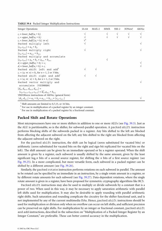
amounts allowed are by one, two, or three bits, and the arithmetic is performed with signed saturation,for 16-bit subwords.
Vector Multiplication
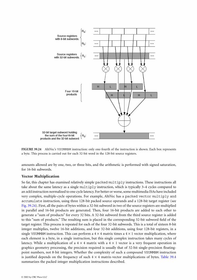
So far, this chapter has examined relatively simple packed multiply instructions. These instructions alltake about the same latency as a single multiply instruction, which is typically 3–4 cycles compared toan add instruction normalized to one cycle latency. For better or worse, some multimedia ISAs have includedvery complex, multiple-cycle operations. For example, AltiVec has a packed vector multiply andaccumulate instruction, using three 128-bit packed source operands and a 128-bit target register (seeFig. 39.24). First, all the pairs of bytes within a 32-bit subword in two of the source registers are multipliedin parallel and 16-bit products are generated. Then, four 16-bit products are added to each other togenerate a “sum of products” for every 32 bits. A 32-bit subword from the third source register is addedto this “sum of products.” The resulting sum is placed in the corresponding 32-bit subword field of thetarget register. This process is repeated for each of the four 32-bit subwords. This is a total of sixteen 8-bitinteger multiplies, twelve 16-bit additions, and four 32-bit additions, using four 128-bit registers, in asingle VSUMMBM instruction. This can perform a 4 × 4 matrix times a 4 × 1 vector multiplication, whereeach element is a byte, in a single instruction, but this single complex instruction takes many cycles oflatency. While a multiplication of a 4 × 4 matrix with a 4 × 1 vector is a very frequent operation ingraphics geometry processing, the precision required is usually that of 32-bit single-precision floating-point numbers, not 8-bit integers. Whether the complexity of such a compound VSUMMBM instructionis justified depends on the frequency of such 4 × 4 matrix-vector multiplications of bytes. Table 39.4summarizes the packed integer multiplication instructions described.
FIGURE 39.24 AltiVec’s VSUMMBM instruction: only one-fourth of the instruction is shown. Each box representsa byte. This process is carried out for each 32-bit word in the 128-bit source registers.
Most microprocessors have one or more shifters in addition to one or more ALUs (see Fig. 39.3). Just asthe ALU is partitionable, so is the shifter, for subword-parallel operation. A packed shift instructionperforms blocking shifts of the subwords packed in a register. Any bits shifted to the left are blockedfrom affecting the adjacent subword on the left; any bits shifted to the right are blocked from affectingthe adjacent subword on the right.
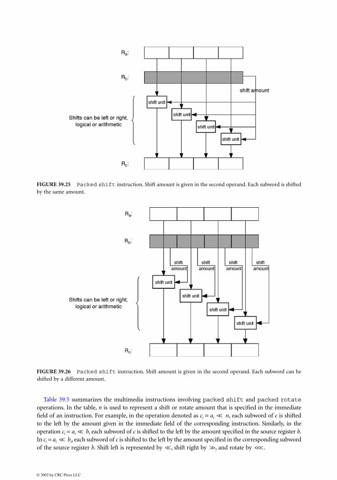
For the packed shift instruction, the shift can be logical (zeros substituted for vacated bits) orarithmetic (zeros substituted for vacated bits on the right and sign-bit replicated for vacated bits on theleft). The shift amount can be given by an immediate operand or by a register operand. When the shiftamount is given by a register, each subword is usually shifted by the same amount, given by the leastsignificant log2n bits of a second source register, for shifting the n bits of a first source register (seeFig. 39.25). In a more complicated, but more versatile form, each subword in a packed register can beshifted by a different amount (see Fig. 39.26).
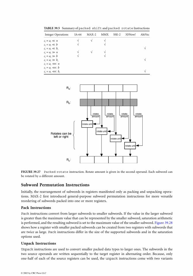
Similarly, the packed rotate instruction performs rotations on each subword in parallel. The amountto be rotated can be specified by an immediate in an instruction, by a single rotate amount in a register, orby different rotate amounts for each subword (see Fig. 39.27). Data-dependent rotations, where the singlerotate amount is given in a register, have been proposed for symmetric cryptography algorithms like RC5. Packed shift instructions may also be used to multiply or divide subwords by a constant that is a
power of two. When used in this way, it may be necessary to apply saturation arithmetic with parallelleft shifts used for multiplication. It may also be desirable to apply rounding with parallel arithmeticright shifts. Such saturation and rounding complicate the circuitry for the shifter functional unit, and isnot implemented by any of the current multimedia ISAs. Hence, packed shift instructions should beused for multiplication or division only when no overflow can occur on left shifts, and sufficient precisioncan be preserved on right shifts. For multiplication by an integer or fractional constant, packed shiftand add instructions, described in the subsection on “Multiplication of a Packed Integer Register by anInteger Constant,” are preferable. These can better control accuracy in the multiplication.
a Shift amounts are limited to 0,7,15, or 16 bits.b For use in multiplication of a packed register by an integer constant.c For use in multiplication of a packed register by a fractional constant.
Table 39.5 summarizes the multimedia instructions involving packed shift and packed rotateoperations. In the table, n is used to represent a shift or rotate amount that is specified in the immediatefield of an instruction. For example, in the operation denoted as ci = ai << n, each subword of c is shiftedto the left by the amount given in the immediate field of the corresponding instruction. Similarly, in theoperation ci = ai << b, each subword of c is shifted to the left by the amount specified in the source register b.In ci = ai << bi, each subword of c is shifted to the left by the amount specified in the corresponding subwordof the source register b. Shift left is represented by <<, shift right by >>, and rotate by <<< .
FIGURE 39.25 Packed shift instruction. Shift amount is given in the second operand. Each subword is shiftedby the same amount.
FIGURE 39.26 Packed shift instruction. Shift amount is given in the second operand. Each subword can beshifted by a different amount.
Initially, the rearrangement of subwords in registers manifested only as packing and unpacking opera-tions. MAX-2 first introduced general-purpose subword permutation instructions for more versatilereordering of subwords packed into one or more registers.
Pack Instructions
Pack instructions convert from larger subwords to smaller subwords. If the value in the larger subwordis greater than the maximum value that can be represented by the smaller subword, saturation arithmeticis performed, and the resulting subword is set to the maximum value of the smaller subword. Figure 39.28shows how a register with smaller packed subwords can be created from two registers with subwords thatare twice as large. Pack instructions differ in the size of the supported subwords and in the saturationoptions used.
Unpack Instructions
Unpack instructions are used to convert smaller packed data types to larger ones. The subwords in thetwo source operands are written sequentially to the target register in alternating order. Because, onlyone-half of each of the source registers can be used, the unpack instructions come with two variants
TABLE 39.5 Summary of packed shift and packed rotate Instructions
unpack high or unpack low. The high/low unpack instructions select and unpack the high or loworder subwords of a source register, when used with register zero as the second source register.5
Subword Permutation Instructions
Ideally, it is desirable to be able to perform all possible permutations on packed data. This is only possiblefor small numbers of subwords. When the number of subwords increases, the number of control bitsrequired to specify arbitrary permutations becomes too large to be encoded in an instruction. For the caseof n subwords, the number of control bits used to specify a particular permutation of these n subwords
FIGURE 39.28 Pack instruction converts larger subwords to smaller ones.
FIGURE 39.29 Unpack high instruction.
FIGURE 39.30 Unpack low instruction.
5Register zero gives a constant value of “zero” when used as a source register.
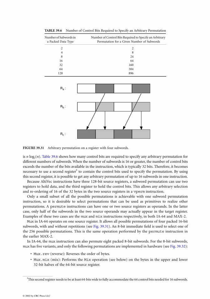
is n log2(n). Table 39.6 shows how many control bits are required to specify any arbitrary permutation fordifferent numbers of subwords. When the number of subwords is 16 or greater, the number of control bitsexceeds the number of the bits available in the instruction, which is typically 32 bits. Therefore, it becomesnecessary to use a second register6 to contain the control bits used to specify the permutation. By usingthis second register, it is possible to get any arbitrary permutation of up to 16 subwords in one instruction.
Because AltiVec instructions have three 128-bit source registers, a subword permutation can use tworegisters to hold data, and the third register to hold the control bits. This allows any arbitrary selectionand re-ordering of 16 of the 32 bytes in the two source registers in a vperm instruction.
Only a small subset of all the possible permutations is achievable with one subword permutationinstruction, so it is desirable to select permutations that can be used as primitives to realize otherpermutations. A permute instructions can have one or two source registers as operands. In the lattercase, only half of the subwords in the two source operands may actually appear in the target register.Examples of these two cases are the mux and mix instructions respectively, in both IA-64 and MAX-2.Mux in IA-64 operates on one source register. It allows all possible permutations of four packed 16-bit
subwords, with and without repetitions (see Fig. 39.31). An 8-bit immediate field is used to select one ofthe 256 possible permutations. This is the same operation performed by the permute instruction inthe earlier MAX-2.
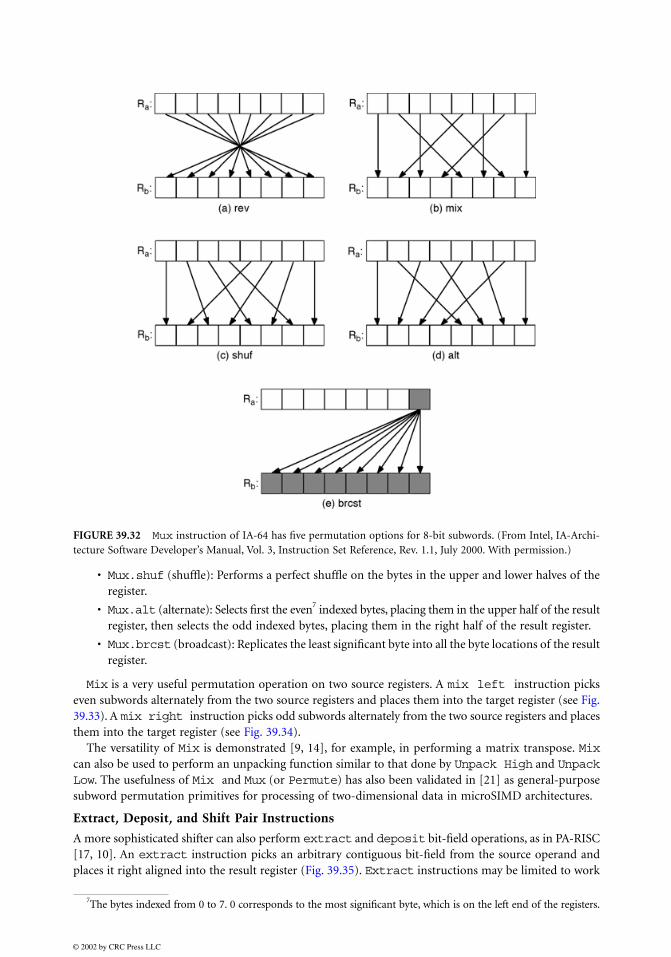
In IA-64, the mux instruction can also permute eight packed 8-bit subwords. For the 8-bit subwords,mux has five variants, and only the following permutations are implemented in hardware (see Fig. 39.32):
• Mux.rev (reverse): Reverses the order of bytes.
• Mux.mix (mix): Performs the Mix operation (see below) on the bytes in the upper and lower32-bit halves of the 64-bit source register.
TABLE 39.6 Number of Control Bits Required to Specify an Arbitrary Permutation
Number of Subwords in a Packed Data Type
Number of Control Bits Required to Specify an Arbitrary Permutation for a Given Number of Subwords
2 24 88 24
16 6432 16064 384
128 896
FIGURE 39.31 Arbitrary permutation on a register with four subwords.
6This second register needs to be at least 64-bits wide to fully accommodate the 64 control bits needed for 16 subwords.
• Mux.shuf (shuffle): Performs a perfect shuffle on the bytes in the upper and lower halves of theregister.
• Mux.alt (alternate): Selects first the even7 indexed bytes, placing them in the upper half of the resultregister, then selects the odd indexed bytes, placing them in the right half of the result register.
• Mux.brcst (broadcast): Replicates the least significant byte into all the byte locations of the resultregister.
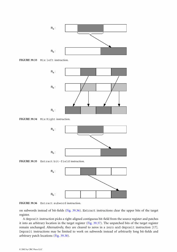
Mix is a very useful permutation operation on two source registers. A mix left instruction pickseven subwords alternately from the two source registers and places them into the target register (see Fig.39.33). A mix right instruction picks odd subwords alternately from the two source registers and placesthem into the target register (see Fig. 39.34).
The versatility of Mix is demonstrated [9, 14], for example, in performing a matrix transpose. Mixcan also be used to perform an unpacking function similar to that done by Unpack High and UnpackLow. The usefulness of Mix and Mux (or Permute) has also been validated in [21] as general-purposesubword permutation primitives for processing of two-dimensional data in microSIMD architectures.
Extract, Deposit, and Shift Pair Instructions
A more sophisticated shifter can also perform extract and deposit bit-field operations, as in PA-RISC[17, 10]. An extract instruction picks an arbitrary contiguous bit-field from the source operand andplaces it right aligned into the result register (Fig. 39.35). Extract instructions may be limited to work
FIGURE 39.32 Mux instruction of IA-64 has five permutation options for 8-bit subwords. (From Intel, IA-Archi-tecture Software Developer’s Manual, Vol. 3, Instruction Set Reference, Rev. 1.1, July 2000. With permission.)
7The bytes indexed from 0 to 7. 0 corresponds to the most significant byte, which is on the left end of the registers.
on subwords instead of bit-fields (Fig. 39.36). Extract instructions clear the upper bits of the targetregister.
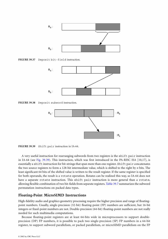
A deposit instruction picks a right-aligned contiguous bit-field from the source register and patchesit into an arbitrary location in the target register (Fig. 39.37). The unpatched bits of the target registerremain unchanged. Alternatively, they are cleared to zeros in a zero and deposit instruction [17].Deposit instructions may be limited to work on subwords instead of arbitrarily long bit-fields andarbitrary patch locations (Fig. 39.38).
A very useful instruction for rearranging subwords from two registers is the shift pair instructionin IA-64 (see Fig. 39.39). This instruction, which was first introduced in the PA-RISC ISA [10,17], isessentially a shift instruction for bit-strings that span more than one register. Shift pair concatenatesthe two source registers to form a 128-bit intermediate value, which is shifted to the right by n bits. Theleast significant 64 bits of the shifted value is written to the result register. If the same register is specifiedfor both operands, the result is a rotate operation. Rotates can be realized this way, so IA-64 does nothave a separate rotate instruction. This shift pair instruction is more general than a rotate,allowing flexible combination of two bit-fields from separate registers. Table 39.7 summarizes the subwordpermutation instructions on packed data types.
Floating-Point MicroSIMD Instructions
High-fidelity audio and graphics geometry processing require the higher precision and range of floating-point numbers. Usually, single-precision (32-bit) floating-point (FP) numbers are sufficient, but 16-bitintegers or fixed-point numbers are not. Double-precision (64-bit) floating-point numbers are not reallyneeded for such multimedia computations.
Because floating-point registers are at least 64-bits wide in microprocessors to support double-precision (DP) FP numbers, it is possible to pack two single-precision (SP) FP numbers in a 64-bitregister, to support subword parallelism, or packed parallelism, or microSIMD parallelism on the FP
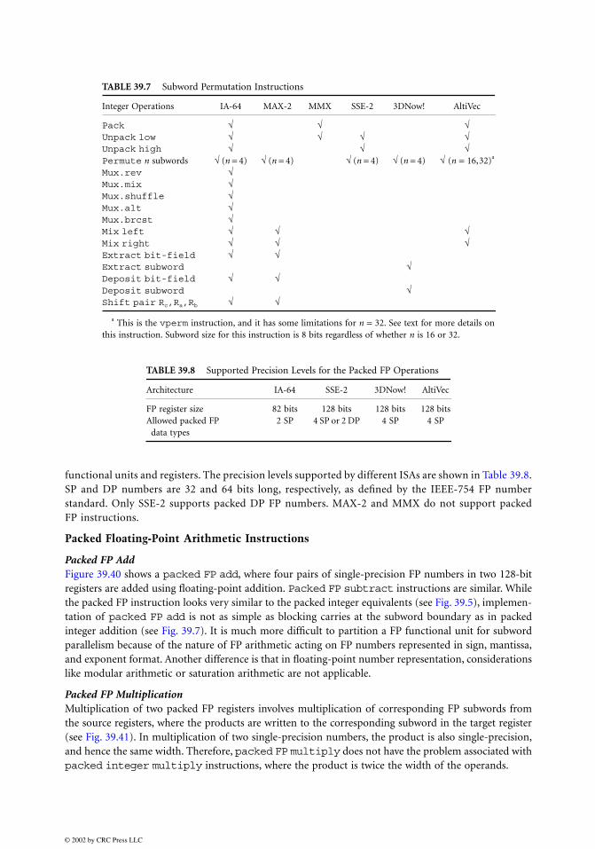
functional units and registers. The precision levels supported by different ISAs are shown in Table 39.8.SP and DP numbers are 32 and 64 bits long, respectively, as defined by the IEEE-754 FP numberstandard. Only SSE-2 supports packed DP FP numbers. MAX-2 and MMX do not support packedFP instructions.
Packed Floating-Point Arithmetic Instructions
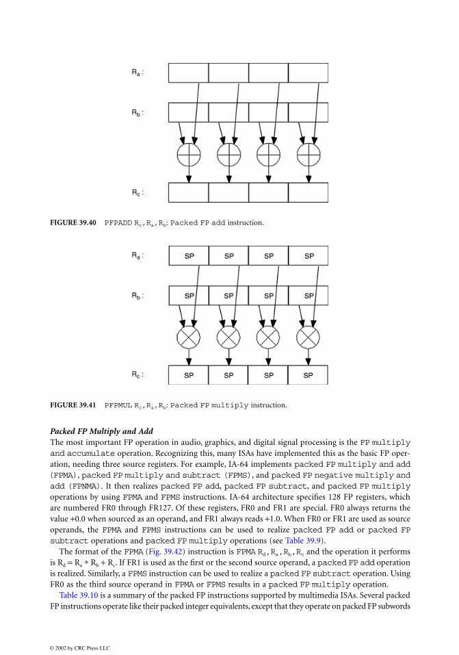
Packed FP AddFigure 39.40 shows a packed FP add, where four pairs of single-precision FP numbers in two 128-bitregisters are added using floating-point addition. Packed FP subtract instructions are similar. Whilethe packed FP instruction looks very similar to the packed integer equivalents (see Fig. 39.5), implemen-tation of packed FP add is not as simple as blocking carries at the subword boundary as in packedinteger addition (see Fig. 39.7). It is much more difficult to partition a FP functional unit for subwordparallelism because of the nature of FP arithmetic acting on FP numbers represented in sign, mantissa,and exponent format. Another difference is that in floating-point number representation, considerationslike modular arithmetic or saturation arithmetic are not applicable.
Packed FP MultiplicationMultiplication of two packed FP registers involves multiplication of corresponding FP subwords fromthe source registers, where the products are written to the corresponding subword in the target register(see Fig. 39.41). In multiplication of two single-precision numbers, the product is also single-precision,and hence the same width. Therefore, packed FP multiply does not have the problem associated withpacked integer multiply instructions, where the product is twice the width of the operands.
a This is the vperm instruction, and it has some limitations for n = 32. See text for more details onthis instruction. Subword size for this instruction is 8 bits regardless of whether n is 16 or 32.
TABLE 39.8 Supported Precision Levels for the Packed FP Operations
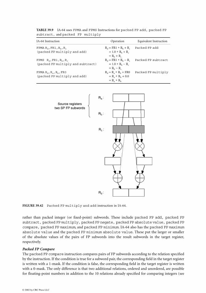
Packed FP Multiply and AddThe most important FP operation in audio, graphics, and digital signal processing is the FP multiplyand accumulate operation. Recognizing this, many ISAs have implemented this as the basic FP oper-ation, needing three source registers. For example, IA-64 implements packed FP multiply and add(FPMA), packed FP multiply and subtract (FPMS), and packed FP negative multiply andadd (FPNMA). It then realizes packed FP add, packed FP subtract, and packed FP multiplyoperations by using FPMA and FPMS instructions. IA-64 architecture specifies 128 FP registers, whichare numbered FR0 through FR127. Of these registers, FR0 and FR1 are special. FR0 always returns thevalue +0.0 when sourced as an operand, and FR1 always reads +1.0. When FR0 or FR1 are used as sourceoperands, the FPMA and FPMS instructions can be used to realize packed FP add or packed FPsubtract operations and packed FP multiply operations (see Table 39.9).
The format of the FPMA (Fig. 39.42) instruction is FPMA Rd,Ra,Rb,Rc and the operation it performsis Rd = Ra ∗ Rb + Rc. If FR1 is used as the first or the second source operand, a packed FP add operationis realized. Similarly, a FPMS instruction can be used to realize a packed FP subtract operation. UsingFR0 as the third source operand in FPMA or FPMS results in a packed FP multiply operation.
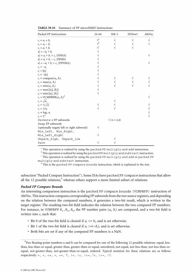
Table 39.10 is a summary of the packed FP instructions supported by multimedia ISAs. Several packedFP instructions operate like their packed integer equivalents, except that they operate on packed FP subwords
rather than packed integer (or fixed-point) subwords. These include packed FP add, packed FPsubtract, packed FP multiply, packed FP negate, packed FP absolute value, packed FPcompare, packed FP maximum, and packed FP minimum. IA-64 also has the packed FP maximumabsolute value and the packed FP minimum absolute value. These put the larger or smallerof the absolute values of the pairs of FP subwords into the result subwords in the target register,respectively.
Packed FP CompareThe packed FP compare instruction compares pairs of FP subwords according to the relation specifiedby the instruction. If the condition is true for a subword pair, the corresponding field in the target registeris written with a 1-mask. If the condition is false, the corresponding field in the target register is writtenwith a 0-mask. The only difference is that two additional relations, ordered and unordered, are possiblefor floating-point numbers in addition to the 10 relations already specified for comparing integers (see
TABLE 39.9 IA-64 uses FPMA and FPMS Instructions for packed FP add, packed FP subtract, and packed FP multiply
subsection “Packed Compare Instruction”). Some ISAs have packed FP compare instructions that allowall the 12 possible relations,8 whereas others support a more limited subset of relations.
Packed FP Compare BoundsAn interesting comparison instruction is the packed FP compare bounds (VCMPBFP) instruction ofAltiVec. This instruction compares corresponding FP subwords from the two source registers, and dependingon the relation between the compared numbers, it generates a two-bit result, which is written to thetarget register. The resulting two-bit field indicates the relation between the two compared FP numbers.For instance, in VCMPBFP Rc,Ra,Rb, the FP number pairs (ai, bi) are compared, and a two-bit field iswritten into ci such that:
• Bit 0 of the two-bit field is cleared if ai <= bi, and is set otherwise.
• Bit 1 of the two-bit field is cleared if ai >=(−bi), and is set otherwise.
• Both bits are set if any of the compared FP numbers is a NaN.
TABLE 39.10 Summary of FP microSIMD Instructions
Packed FP Instructions IA-64 SSE-2 3DNow! AltiVec
ci = ai + bi √a √ √ √ci = ai − bi √b √ √ √ci = ai ∗ bi √c √ √di = −ai ∗ bi √di = ai ∗ bi + ci (FPMA) √ √di = ai ∗ bi − ci (FPMS) √di = −ai ∗ bi + ci (FPNMA) √ √ci = −ai √ci = |ai| √ci = −|ai| √ci = compare(ai, bi) √ √ √ √ci = max(ai, bi) √ √ √ √ci = min(ai, bi) √ √ √ √ci = max(|ai|, |bi|) √ci = min(|ai|, |bi|) √ci = VCMPBFB(ai, bi)
d √ci = √ci = 1/ √ √ √ci = 1/ai √ √ √ci = log2 ai √ci = √Permute n FP subwords √ (n = 2,4)Swap FP subwords(optionally negate left or right subword) √Mix_Left, Mix_Right,Mix_Left_Right √Unpack_high, Unpack_low √Pack √ √
a This operation is realized by using the packed FP multiply and add instruction.b This operation is realized by using the packed FP multiply and subtract instruction.c This operation is realized by using the packed FP multiply and add or packed FP
multiply and subtract instruction.d This is the packed FP compare bounds instruction, which is explained in the text.
8Two floating-point numbers a and b can be compared for one of the following 12 possible relations: equal, less-than, less-than-or-equal, greater-than, greater-than-or-equal, unordered, not-equal, not-less-than, not-less-than-or-equal, not-greater-than, not-greater-than-or-equal, ordered. Typical notation for these relations are as followsrespectively: =, <, <=, >, >=, ?, !=, !<, !<=, !>, !>=, !?.
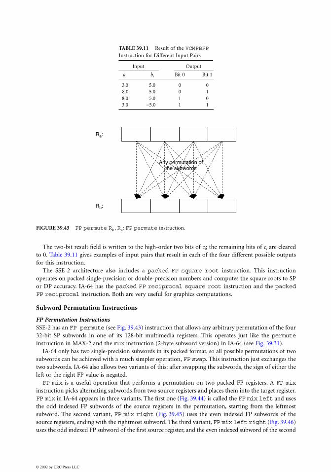
The two-bit result field is written to the high-order two bits of ci; the remaining bits of ci are clearedto 0. Table 39.11 gives examples of input pairs that result in each of the four different possible outputsfor this instruction.
The SSE-2 architecture also includes a packed FP square root instruction. This instructionoperates on packed single-precision or double-precision numbers and computes the square roots to SPor DP accuracy. IA-64 has the packed FP reciprocal square root instruction and the packedFP reciprocal instruction. Both are very useful for graphics computations.
Subword Permutation Instructions
FP Permutation InstructionsSSE-2 has an FP permute (see Fig. 39.43) instruction that allows any arbitrary permutation of the four32-bit SP subwords in one of its 128-bit multimedia registers. This operates just like the permuteinstruction in MAX-2 and the mux instruction (2-byte subword version) in IA-64 (see Fig. 39.31).
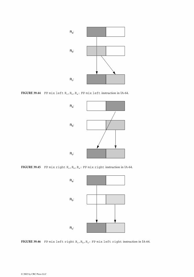
IA-64 only has two single-precision subwords in its packed format, so all possible permutations of twosubwords can be achieved with a much simpler operation, FP swap. This instruction just exchanges thetwo subwords. IA-64 also allows two variants of this: after swapping the subwords, the sign of either theleft or the right FP value is negated.FP mix is a useful operation that performs a permutation on two packed FP registers. A FP mix
instruction picks alternating subwords from two source registers and places them into the target register.FP mix in IA-64 appears in three variants. The first one (Fig. 39.44) is called the FP mix left and usesthe odd indexed FP subwords of the source registers in the permutation, starting from the leftmostsubword. The second variant, FP mix right (Fig. 39.45) uses the even indexed FP subwords of thesource registers, ending with the rightmost subword. The third variant, FP mix left right (Fig. 39.46)uses the odd indexed FP subword of the first source register, and the even indexed subword of the second
TABLE 39.11 Result of the VCMPBFP Instruction for Different Input Pairs
source register. These three FP mix instructions, together with the Shift Pair instruction describedearlier, allow any one of the four combinations of the SP subwords packed into two IA-64 registers tobe achieved with only one instruction.
FP UnpackPacking and unpacking subwords has a different interpretation for FP numbers than for integers. Ingeneral, there is sufficient precision in single-precision numbers, and there is no need to unpack it toa double-precision number; however, the FP unpack can be regarded as a useful subword permutationinstruction like FP mix. It performs a shuffle by interleaving the subwords from two registers. TheFP unpack instructions operate just like the equivalent integer unpack instructions (see Figs. 39.29 and39.30). They come in two “flavors”: FP unpack high and FP unpack low. Note that the SSE-2 employsFP unpack, after unpack in MMX, and IA-64 employs FP mix, after mix in MAX-2.
FP PackIn the integer domain, pack instructions are used to create smaller packed data types from larger datatypes. The FP pack instruction in IA-64 creates two packed SP numbers from two 82-bit source registers.All IA-64 FP registers are 82-bit extended precision FP format with two extra guard bits for computationalaccuracy. First, the two 82-bit numbers are converted to standard 32-bit SP representation. These twoSP numbers are then concatenated and the result is stored in the significand field (which is 64 bits) ofthe 82-bit target FP register. The exponent field of the target register is set to the biased exponent for2.063, which indicates a packed FP format, and the sign bit is set to zero, indicating a positive number.
Conclusions
Section 39.1 described multimedia instructions for programmable processors by broad classes accordingto the functional units used, first in the integer domain then in the floating-point domain. For integersubwords, packed add and packed subtract instructions, and different variants of these, use theALU. Packed multiply instructions use the multiplier functional unit, although very efficient mul-tiplication by constants can be implemented with packed shift and add instructions, which onlyneed an ALU with a preshifter. Packed shift and packed rotate instructions use the shifter. Packedsubword permutation instructions can either be implemented on a modified shifter or in a new permu-tation unit. For packed floating-point subwords, less leverage of hardware seems possible. The basicfunctional units are a floating-point adder, multiplier, and FP subword permutation unit. IA-64 combinesthe FP adder and multiplier into an FP multiply-add unit. For each of these instruction classes, interestingmultimedia instructions introduced in current microprocessors were described, for example, in the IA-64, MMX, and SSE-2 from Intel; MAX-2 from Hewlett-Packard; 3DNow! from AMD; and AltiVec fromMotorola.
The key feature in these multimedia instructions is the concept of subword parallelism, also calledpacked parallelism or microSIMD parallelism. This is implemented for packed integers or fixed-pointnumbers in the integer datapaths, and for packed floating-point numbers in the floating-point datapaths.Visual multimedia data like images, video, graphics rendering and animation involve pixel processing,which can fully exploit subword parallelism on the integer datapath. Higher-fidelity audio processing andgraphics geometry processing require single-precision floating-point computations, which exploit subwordparallelism on the floating-point datapath. Typical DSP operations such as multiply and accumulatehave also been added to the multimedia repertoire of general-purpose microprocessors. These multimediainstructions have embedded DSP and visual processing capabilities into general-purpose microprocessors,providing native signal processing (sometimes referred to as NSP) for multimedia data. In fact, mostDSPs and media processors have also adopted subword parallelism in their architectures, as well as otherfeatures often first introduced in microprocessors for multimedia signal processing.
More unusual computer arithmetic issues arising from subword-parallel multimedia instructions inmicroprocessors are saturation arithmetic, integer rounding alternatives, integer multiplication problemsand solutions, and subword permutation instructions.
Some of the multimedia ISAs introduced in microprocessors adhere to the “less is more” minimalistarchitecture approach, defining as few instructions as necessary for high-performance, with each instruc-tion executable in a single pipeline cycle. Others embody the “more is better” approach, where complexsequences of operations are represented by a single multimedia instruction, with such an instructiontaking many cycles for execution. An example is the packed vector multiply and accumulateinstruction in AltiVec (Fig. 39.24). These two trends represent different stylistic preferences, akin toreduced instruction set computer (RISC) and complex instruction set computer (CISC) architecturalpreferences. In fact, sometimes, RISC-like multimedia instructions have been added to CISC processorISAs, and CISC-like multimedia instructions to RISC processor ISAs. The remarkable fact is that subword-parallel multimedia instructions have achieved such rapid and pervasive adoption in both RISC andCISC microprocessors, DSPs and media processors, attesting to their undisputed cost-effectiveness inaccelerating multimedia processing in software.
To simplify software compatibility and interoperability of multimedia software across different pro-cessors, it is highly desirable to refine the best ideas from the different multimedia ISAs into a coherentset of subword-parallel instructions. If this is a small yet powerful set, it is more likely to be implementedin all future microprocessors and media processors, allowing algorithm and compiler optimizations toexploit microSIMD parallelism with confidence that benefits would be realized across almost all proces-sors. While slight differences in multimedia instructions across processors may not affect the potentialperformance provided by each ISA, they make it difficult to design an optimal algorithm and a set ofcompiler optimizations that achieve the best multimedia performance for every processor. The challengefor the next phase of multimedia ISA design is to understand which ISA features are truly effective formultimedia signal processing, and encapsulate these insights into the design of third-generation multi-media ISA for both microprocessors and media processors.
Acknowledgments
The author thanks her student, A. Murat Fiskiran, for surveying SSE-2, 3DNow! and AltiVec, and for hisinvaluable help in preparing the figures and tables.
References
1. Ruby Lee and Michael Smith, “Media processing: a new design target,” IEEE Micro, Vol. 16, No. 4,pp. 6–9, Aug. 1996.
2. Michael Flynn, “Very high-speed computing systems,” Proceedings of the IEEE, No. 54, Dec. 1966.3. Ruby Lee, “Efficiency of MicroSIMD architectures and index-mapped data for media processors,”
Proceedings of IS&T/SPIE Symposium on Electric Imaging: Media Processors 99, pp. 34–46, Jan. 1999.4. Intel, “IA-64 architecture software developer’s manual, volume 3: instruction set reference,” Revision
1.1, July 2000, Order Code 245319-002.5. Ruby Lee, Murat Fiskiran, and Abdulla Bubshait, “Multimedia instructions in IA-64,” Invited paper.
Proceedings of the 2001 IEEE International Conference on Multimedia and Exposition, Aug. 22–24, 2001.6. Alex Peleg and Uri Weiser, “MMX technology extension to the intel architecture,” IEEE Micro, Vol. 16,
No. 4, pp. 10–20, Aug. 1996.7. Intel, “Intel architecture software developer’s manual, volume 2: instruction set reference,” 1999,
Order Code 243191.8. Intel, “IA-32 intel architecture software developer’s manual with preliminary willamette architecture
information, volume 2: instruction set reference,” 2000.9. Ruby Lee, “Subword parallelism with MAX-2,” IEEE Micro, Vol. 16, No. 4, pp. 51–59, Aug. 1996.
10. G. Kane, “PA-RISC 2.0 architecture,” 1996, Prentice-Hall, Englewood Cliffs, NJ.11. AMD, “3DNow! technology manual,” March 2000, Order Code 21928G/0.12. AMD, “AMD extensions to the 3DNow! and MMX Instruction Sets Manual,” March 2000, Order
14. Ruby Lee, “Multimedia extensions for general-purpose processors,” Invited paper. Proceedings of theIEEE Signal Processing Systems:Design and Implementation, pp. 9–23. Nov. 1997.
15. Ruby Lee, “Accelerating multimedia with enhanced microprocessors,” IEEE Micro, Vol. 15, No. 2,pp. 22–32, April 1995.
16. Ruby Lee, John Beck, Joel Lamb, and Ken Severson, “Real-time software MPEG video decoder onmultimedia-enhanced PA7100LC processors,” Hewlett-Packard Journal, Vol. 46, No. 2, pp. 60–68,April 1995.
17. Ruby Lee, “Precision architecture,” IEEE Computer, Vol. 22, No. 1, pp. 78–91, Jan. 1989.18. Vasudev Bhaskaran, Konstantine Konstantinides, Ruby Lee and John Beck, “Algorithmic and archi-
tectural enhancements for real-time MPEG-1 decoding on a general purpose RISC workstation,”IEEE Transactions on Circuits and Systems for Video Technology, Vol. 5, No. 5, pp. 380–386, Oct. 1995.
19. Mark Tremblay, J. M. O’Connor, V. Narayanan, and H. Liang, “VIS speeds new media processing,”IEEE Micro, Vol. 16, No. 4, pp. 10–20, Aug. 1996.
20. Zhen Luo and Ruby Lee, “Cost-effective multiplication with enhanced adders for multimedia appli-cations,” Proceedings of ISCAS 2000, IEEE International Symposium on Circuits and Systems, Vol. I,pp. 651–654, May 2000.
21. Ruby Lee, “Subword permutation instructions for two-dimensional multimedia processing in Micro-SIMD architectures,” Proceedings of the IEEE International Conference on Application-specific Systems,Architectures and Processors, pp. 3–14, July 2000.
39.2 DSP Platform Architecture for SoC Products
Gerald G. Pechanek
Introduction
The development of wireless, networking, communications, video, and consumer products has shiftedtoward low-power high-functionality systems-on-chip (SoC) semiconductors [1]. Driving this develop-ment is the availability of deep sub-micron technology allowing more complete system designs to beembedded in silicon. Some of these improvements include increasing on-chip memory capacity, the useof more fully programmable solutions using DSPs, and the inclusion of specialized interfaces and functions.
To make these high-value SoC products widely available at low cost requires the use of standard designpractices that allow them to be fabricated at multiple semiconductor suppliers. This means that customdesigned SoCs, optimized to a particular manufacturing process, cannot be used. Consequently, as thecomplexity and functionality of SoC products continues to increase with stringent power requirements,the standard approach of increasing clock speed on an existing design to meet higher performancerequirements is infeasible.
The need to support multiple standards, and to quickly adapt to changing standards, has become aproduct requirement [2]. To satisfy this need, programmable DSPs and control processors are beingincreasingly used as the central SoC design component. These processors form the basis of the SoCproduct platform and permeate the overall system design including the on-chip memory, DMA, internalbusses, etc. Consequently, choosing a flexible and efficient processor, which can be manufactured bymultiple semiconductor suppliers, is arguably the most important intellectual property (IP) decision thatneeds to be made in the creation of an SoC product.
In recent years, a class of high-performance programmable processor IP has emerged that is appropriatefor use in high-volume embedded applications such as digital cellular, networking, communications, andconsole gaming [3,4]. Section 39.2 briefly describes the ManArray thread coprocessor as an example ofthe architectural features needed for demanding SoC requirements. The next subsection provides a briefdescription of the ManArray thread coprocessor architecture. The subsection “The ManArray Thread