76
MEDICAL APPLICATIONS OF FLUKA 1 Fisica Medica, 2012 G. Battistoni
MEDICAL APPLICATIONS OF FLUKA
1 Fisica Medica, 2012 G. Battistoni
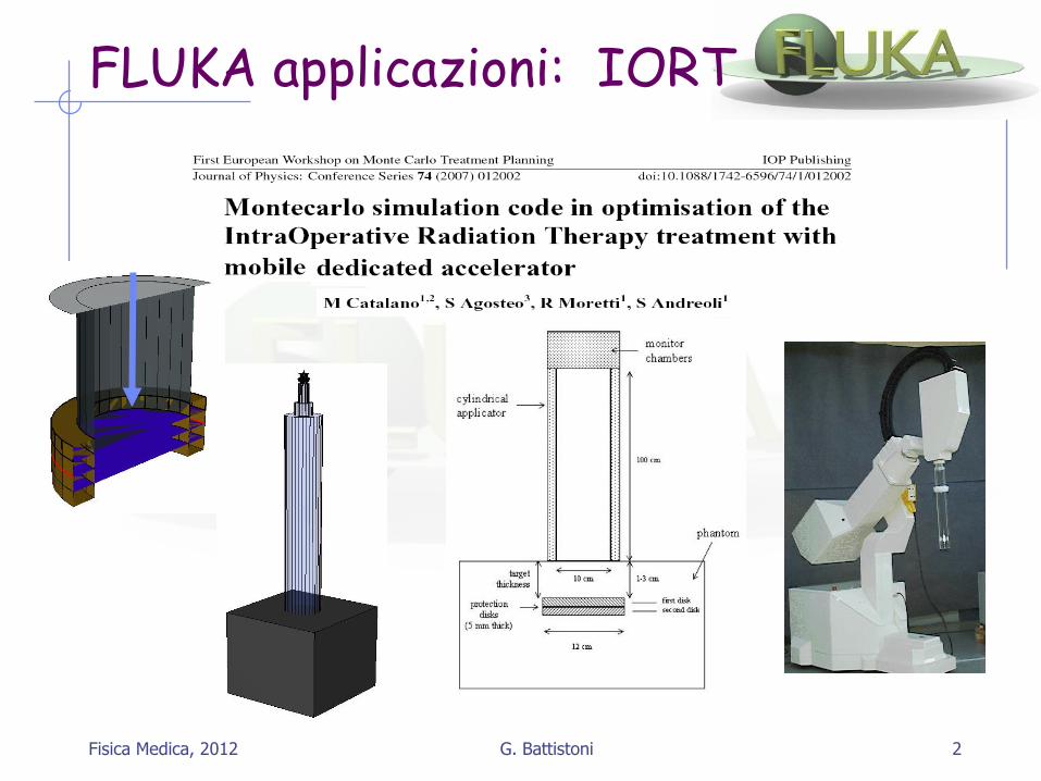
FLUKA applicazioni: IORT
Fisica Medica, 2012 2 G. Battistoni

3
FLUKA Applications: Linac Head
Fisica Medica, 2012 G. Battistoni

Radiotherapy
4
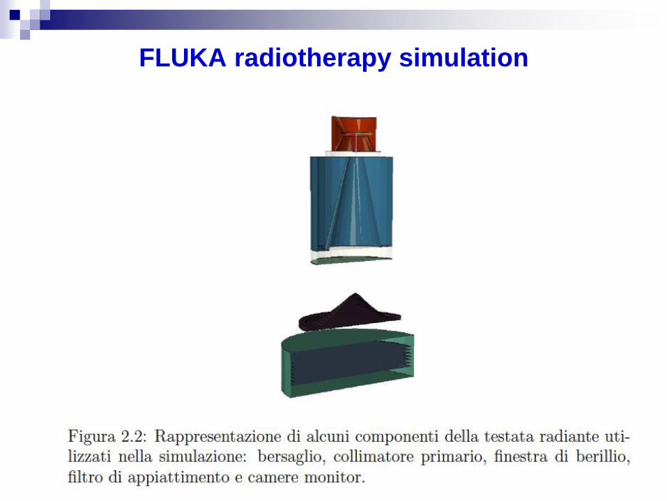
FLUKA radiotherapy simulation
5
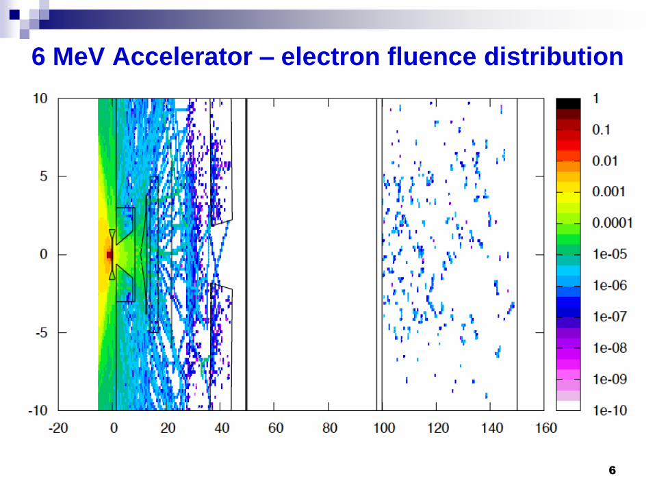
6 MeV Accelerator – electron fluence distribution
6

6 MeV Accelerator –photon fluence distribution
7

FLUKA MONTE CARLO SIMULATION FOR THE LEKSELL GAMMA KNIFE©
PERFEXIONTM
Fisica Medica, 2012 8 G. Battistoni

6 MeV Accelerator
9

6 MeV Accelerator
10

The Leksell Gamma Knife Perfexion (LGK-PFX) is a 60Co based medical device, manufactured by Elekta AB Instruments Stockholm, Sweden. The It is emplyed in the cure of different brain pathologies: small brain and spinal
cord tumors (benign and malignant), blood vessel abnormalities, as well as neurologic problems can be fully treated.
FLUKA Monte Carlo simulation for the Leksell Gamma Knife Perfexion System, Homogeneous media.
The Leksell Gamma Knife Perfexion:
Fabrizio Cappucci INFN, Milan.

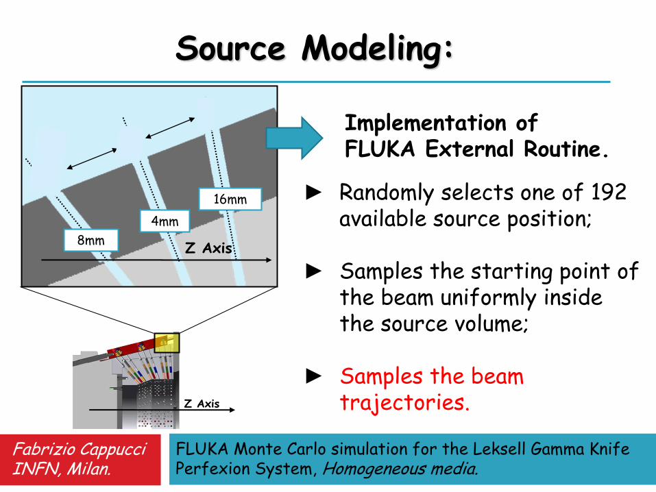
The ionizing gamma radiation is emitted from 192 60Co sources (average activity ~1TBq each). The sources are arranged on 8 identical sectors of 24 elements. The sectors can be placed in correspondence of three different collimation set able to focus the gamma rays on a common spot, called the isocenter of the field, having a radial dimension of about 4, 8 and 16 mm respectively.
FLUKA Monte Carlo simulation for the Leksell Gamma Knife Perfexion System, Homogeneous media.
The Leksell Gamma Knife Perfexion:
Fabrizio Cappucci INFN, Milan.

FLUKA Monte Carlo simulation for the Leksell Gamma Knife Perfexion System, Homogeneous media.
Implementation of the Simulation:
► Geometry Modeling; ► Source Modeling; ► Simulation Optimization.
Definition of the bodies; Definition of the regions (Boolean algebra); Definition of the materials; Assignment of the materials to each region.
Fabrizio Cappucci INFN, Milan.
FLUKA Monte Carlo simulation for the Leksell Gamma Knife Perfexion System, Homogeneous media.
Fabrizio Cappucci INFN, Milan.
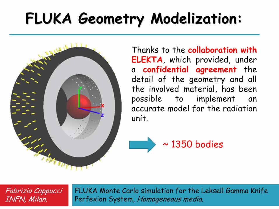
FLUKA Geometry Modelization:
~ 1350 bodies
Thanks to the collaboration with ELEKTA, which provided, under a confidential agreement the detail of the geometry and all the involved material, has been possible to implement an accurate model for the radiation unit.
FLUKA Monte Carlo simulation for the Leksell Gamma Knife Perfexion System, Homogeneous media.
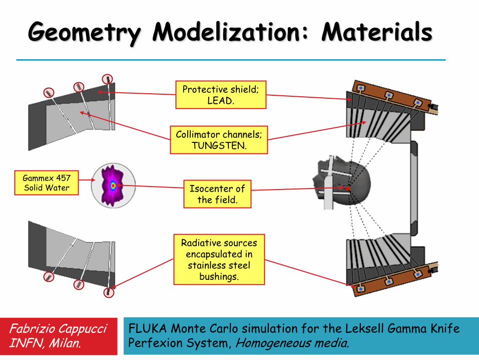
Protective shield; LEAD.
Collimator channels; TUNGSTEN.
Isocenter of the field.
Radiative sources encapsulated in stainless steel
bushings.
Gammex 457 Solid Water
Geometry Modelization: Materials
Fabrizio Cappucci INFN, Milan.
FLUKA Monte Carlo simulation for the Leksell Gamma Knife Perfexion System, Homogeneous media.
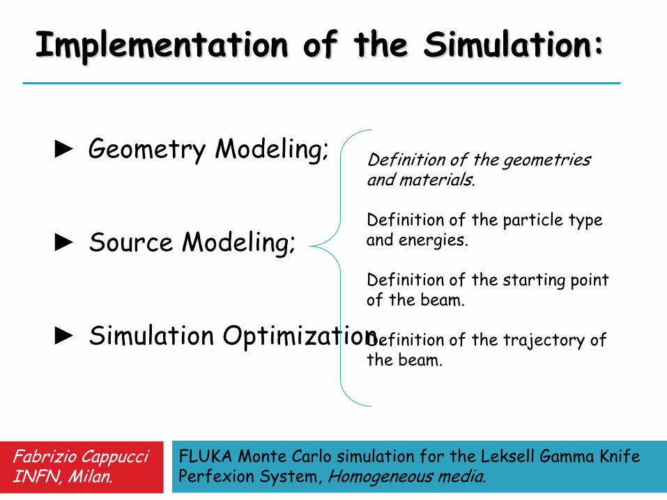
Implementation of the Simulation:
► Geometry Modeling; ► Source Modeling; ► Simulation Optimization.
Definition of the geometries and materials. Definition of the particle type and energies. Definition of the starting point of the beam. Definition of the trajectory of the beam.
Fabrizio Cappucci INFN, Milan.
FLUKA Monte Carlo simulation for the Leksell Gamma Knife Perfexion System, Homogeneous media.
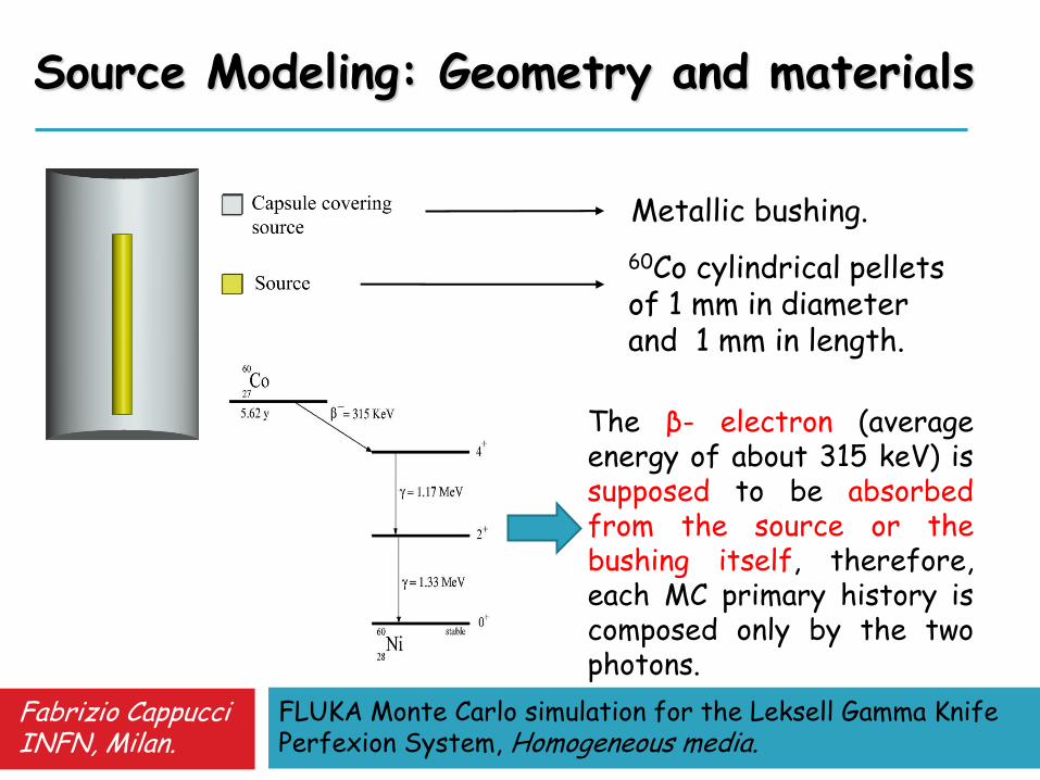
Source Modeling: Geometry and materials
Metallic bushing.
60Co cylindrical pellets of 1 mm in diameter and 1 mm in length.
The β- electron (average energy of about 315 keV) is supposed to be absorbed from the source or the bushing itself, therefore, each MC primary history is composed only by the two photons.
Fabrizio Cappucci INFN, Milan.
FLUKA Monte Carlo simulation for the Leksell Gamma Knife Perfexion System, Homogeneous media.
► Randomly selects one of 192 available source position;
► Samples the starting point of
the beam uniformly inside the source volume;
► Samples the beam
trajectories.
Implementation of FLUKA External Routine.
Z Axis
16mm
4mm
8mm
Source Modeling:
Z Axis
Fabrizio Cappucci INFN, Milan.

FLUKA Monte Carlo simulation for the Leksell Gamma Knife Perfexion System, Homogeneous media.
Implementation of the Simulation:
► Geometry Modeling; ► Source Modeling; ► Simulation Optimization. CPU TIME
Optimizing the energy thresholds for production and transport of the secondary particles.
AVOID the production of secondary charged particles in the radiation unit body.
Fabrizio Cappucci INFN, Milan.
FLUKA Monte Carlo simulation for the Leksell Gamma Knife Perfexion System, Homogeneous media.
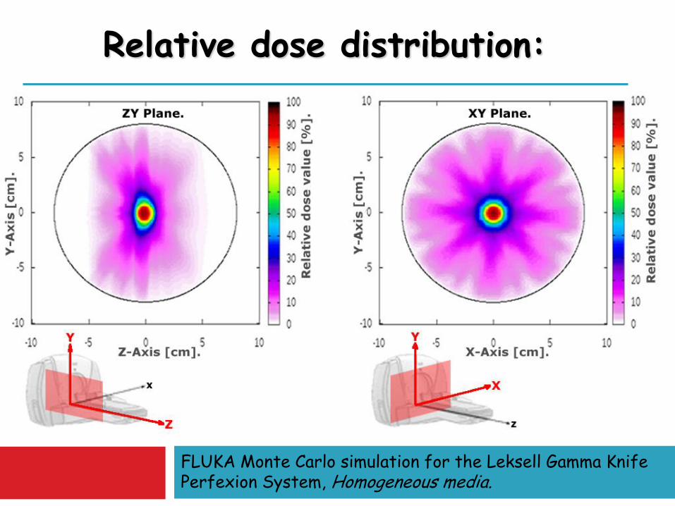
Relative dose distribution:

We have investigated the relative linear dose distribution along the three coordinated axes for each kind of collimator size and the Relative Output Factors (ROF). Monte Carlo results have been compared with LGP data provided by Elekta in the same homogeneous conditions of the target. 4∙109 primary histories (total calculation time of about 20h on 26 nodes) have been performed for each simulation. The simulations have been performed splitting the runs in a Macintosh cluster, made available by the Medical Physics department of Niguarda Ca’Granda Milan Hospital.
Results:

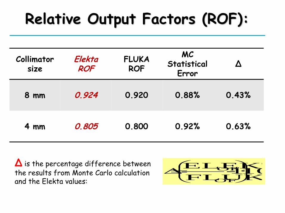
ROFs are the ratio between the dose given by a set of collimators and the dose given by the largest collimators, i.e. the 16 mm.
The Elekta ROFs values are: 1.000 (16 mm); 0.924 (8 mm); 0.805 (4 mm).
The FLUKA scoring volume has been chosen as a cylinder of 1 mm in radius an 1 mm length placed around the isocenter point, with longitudinal axis lying along the Z axis.
Relative Output Factors (ROF):
Relative Output Factors (ROF):
Δ is the percentage difference between the results from Monte Carlo calculation and the Elekta values:
100% · 1-FLUKA
ELEKTA
OF
OF
Collimator size
Elekta ROF
FLUKA ROF
MC Statistical
Error ∆
8 mm
0.924 0.920 0.88% 0.43%
4 mm
0.805 0.800 0.92% 0.63%

The output data distributions of the FLUKA simulation have been smoothed by means of a linear interpolation (spline) with 2% of tolerance. The quality index we used to perform the comparison is base on the Gamma Index (GI) method.
Relative dose profiles: quality index definition
This index takes into account the relative shift both in terms of intensity and in terms of position, combining together the dose difference (DD) and the distance to agreement (DTA) methods. DD is the difference between the dose value in a measured data point and the dose value in a point of the calculated distribution which has the same coordinates. DTA is the distance between a measured data point and the nearest point in the calculated dose distribution that has the same dose value.
By definition, if GI>1 the test is not passed and the two distribution are not in agreement.

Relative dose profile
The acceptance threshold values for DD and DTA are derived from the Report of the American Association of Physicists in Medicine for stereotactic radiosurgery, respectively as DD=3% and DTA=2.4 mm
16mm X profile
8mm Y profile
4mm Z profile
The blue line represents the gamma index trend. It results < 1 for each simulated point, attesting the goodness of the FLUKA model.

Radioactive source decay
26
FLUKA contains data about decaying schemes of
radioactive isotopes, allowing to select an isotope
as radiation source. Complete databases are
generated from the data collected from National
Nuclear Data Center (NNDC) at Brookhaven
National Laboratory. Routines are available to
discriminate only a component of the emission
spectrum, simulating for example only the beta
emission and disregarding the gamma one.
Fisica Medica, 2012 G. Battistoni
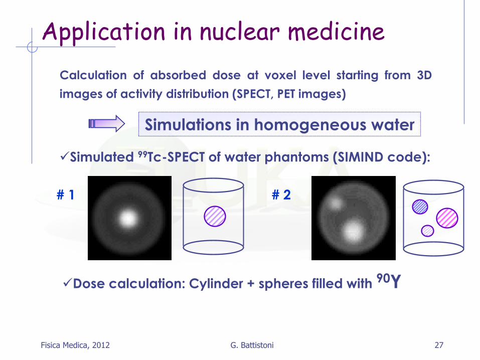
Application in nuclear medicine
Application in nuclear medicine
Calculation of absorbed dose at voxel level starting from 3D
images of activity distribution (SPECT, PET images)
Simulated 99Tc-SPECT of water phantoms (SIMIND code):
Dose calculation: Cylinder + spheres filled with 90Y
Simulations in homogeneous water
# 1 # 2
Fisica Medica, 2012 27 G. Battistoni
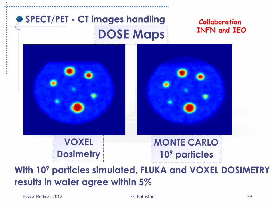
28
SPECT/PET - CT images handling
VOXEL
Dosimetry
MONTE CARLO
109 particles
DOSE Maps
With 109 particles simulated, FLUKA and VOXEL DOSIMETRY
results in water agree within 5%
Fisica Medica, 2012 G. Battistoni
Collaboration INFN and IEO
Rationale for MC in hadron-therapy Biological calculations in tumour therapy with ions depend on
a precise description of the radiation field.
In 12C ion irradiation, nuclear reactions cause a significant alteration of the radiation field.
contribution of secondary fragments needs to be taken into account for accurate planning of the physical and biological dose delivery in the scheduled treatment.
Treatment Planning Systems (TPS) for ion beam therapy essentially use analytical algorithms with input databases for the description of the ion interaction with matter.
→ Monte Carlo codes with sophisticated nuclear models are more efficient (though slower) computational tools to handle the mixed radiation field.
Fisica Medica, 2012 29 G. Battistoni

Rationale for MC in hadron-therapy In practice MC codes can be used for: startup and commissioning of new facilities beamline modeling and generation of TPS input data validate analytical TPSs in water/CT systems both for physical
and biological aspects Prediction/Analysis of in-beam PET application Biological calculations for cell survival experiments
Additional advantage to describe complex geometries (and interfaces between rather different materials!):
Accurate 3D transport Fully detailed description of the patient anatomy → CT image converted into a MC geometry
Model challenge: interface to radiobiological model to predict “biological dose” (→actual effect) and not only physical dose
Fisica Medica, 2012 30 G. Battistoni

G. Battistoni 31
Nuclear reactions: what really matters? Proton therapy (p, E: 10-250 MeV):
Reaction cross sections (beam attenuation) +++
Elastic cross sections +
Particle (p,n,α..) emission + (mostly for background, ++ radiobiology)
Positron emitter production + (data available)
Therapy with ions (ions, E: 10-400 MeV/n): Reaction cross sections (beam attenuation) +++
Fragment (α included) production +++
Particle emission, p +++, others +
Positron emitter production +++
Conventional therapy (γ, E: 3-30 MeV)
(γ,x) (particularly (γ,n)) + (mostly for background)
Fisica Medica, 2012

Main FLUKA developments in view of medical applications (and hadron therapy in particular)
Models for nucleus-nucleus interactions :
Improvement of models for evaporation/fission/fragmentation used in fragment final de-excitation. Prediction of radionuclide production
Improvement of dE/dx models (Z2+Z3 corrections, molecular effects, nuclear stopping power)
Run time application of linear-quadratic models describing radiobiological effects
Extensions and improvement of neutron library (thermal + ephithermal region)
Voxel geometry
Time-varying geometry
Routines to import CT scans, material/density/composition assignment to CT
Fisica Medica, 2012 32 G. Battistoni
Main references to FLUKA in ion-therapy related matters:
1) F.Sommerer, K.Parodi, A.Ferrari, K.Poljanc,W.Enghardt and H.Aiginger, Investigating the accuracy of the FLUKA code for transport of therapeutic ion beams in matter, Phys. Med. Biol. 51 (2006) 4385–4398
2) K.Parodi, A.Ferrari, F.Sommerer and H.Paganetti, Clinical CT-based calculations of dose and positron emitter distributions in proton therapy using the FLUKA Monte Carlo code, Phys. Med. Biol. 52 (2007) 3369–3387
3) A. Mairani, Nucleus-Nucleus Interaction Modelling and Applications in Ion Therapy Treatment Planning, PhD Thesis, Univ. Pavia, 2007
4) G.B. et al. (FLUKA collaboration), The FLUKA code and its use in hadron therapy, Il Nuovo Cimento 31C, no. 1 (2008) 69.
5) F.Sommerer, F.Cerutti, K.Parodi, A.Ferrari, W.Enghardt and H.Aiginger, In-beam PET monitoring of mono-energetic 16O and 12C beams: experiments and FLUKA simulations for homogeneous targets, Phys. Med. Biol. 54 (2009) 3979–3996
6) A.Mairani, S.Brons, A.Fassò, A.Ferrari, M.Krämer, K.Parodi, M.Scholz and F. Sommerer, Monte Carlo based biological calculations in carbon ion therapy: the FLUKA code coupled with the Local Effect Model, submitted to PMB 2010
Fisica Medica, 2012 33 G. Battistoni

G. Battistoni 34
Nuclear interactions: a nuisance x therapy
• … easy to switch off in MonteCarlo, a bit less in real life
• … nice at least I have a good job
• … Nuclear (and particle) physics cannot be simulated at % level, sometimes you are happy with results within a factor of 2
That’s why we always plot results in log-log scales
Fisica Medica, 2012
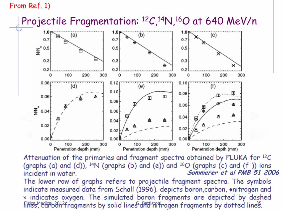
Projectile Fragmentation: 12C,14N,16O at 640 MeV/n
Sommerer et al PMB 51 2006
From Ref. 1)
Fisica Medica, 2012 35 G. Battistoni
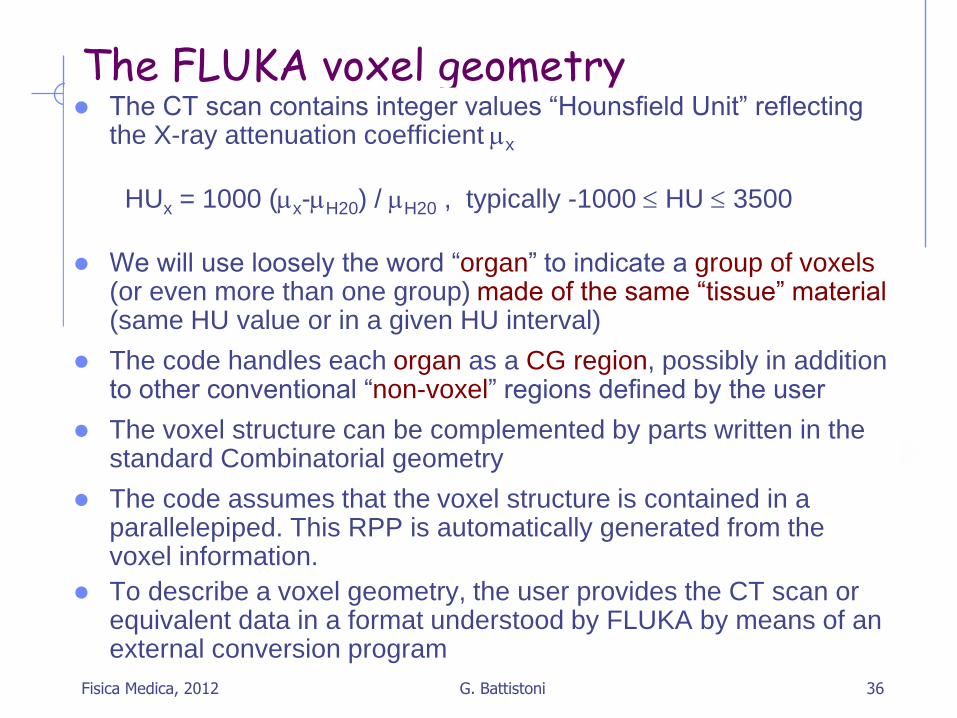
The FLUKA voxel geometry
The CT scan contains integer values “Hounsfield Unit” reflecting the X-ray attenuation coefficient mx
HUx = 1000 (mx-mH20) / mH20 , typically -1000 HU 3500
We will use loosely the word “organ” to indicate a group of voxels (or even more than one group) made of the same “tissue” material (same HU value or in a given HU interval)
The code handles each organ as a CG region, possibly in addition to other conventional “non-voxel” regions defined by the user
The voxel structure can be complemented by parts written in the standard Combinatorial geometry
The code assumes that the voxel structure is contained in a parallelepiped. This RPP is automatically generated from the voxel information.
To describe a voxel geometry, the user provides the CT scan or equivalent data in a format understood by FLUKA by means of an external conversion program
Fisica Medica, 2012 36 G. Battistoni

Voxel geometries: examples The anthropomorphic
GOLEM phantom
Implementation in FLUKA
(radioprotection applications)
Petoussi-Henss
et al, 2002
Now available the official ICRP Human Phantom ICRP Publication 110: Adult Reference Computational Phantoms - Annals
of the ICPR Volume 39 Issue 2
Fisica Medica, 2012 37 G. Battistoni

The FLUKA voxel geometry
This stage should : Assign an organ index to each voxel. In many practical cases,
the user will have a continuum of CT values (HU), and may have to group these values in intervals
Each organ is identified by a unique integer ≤32767. The organ numbering does not need to be contiguous (i.e. “holes” in the numbering sequence are allowed.)
One of the organs must have number 0 and plays the role of the medium surrounding the voxels (usually vacuum or air).
The user assigns to each NONZERO organ a voxel-region number. The voxel-region numbering has to be contiguous and starts from 1.
Fisica Medica, 2012 38 G. Battistoni

Practical issues for Medical Applications
General problems for MC calculations on CT scans
How to assign realistic human tissue parameters (=
materials) for MC Calculation ?
How to find a good compromise between the number
of different HU values (~ 3000-5000) and the materials
to be considered in the MC ?
(issues on memory and computation speed when
attempting to treat each HU number as a different
material !!!)
How to preserve continuous, HU-dependent
information when segmenting the HU numbers into
intervals sharing the same “tissue” material ?
(critical for ion range calculation in charged hadron
therapy !!!) Fisica Medica, 2012 39 G. Battistoni

CT stoichiometric calibration (I)
CT segmentation into 27 materials of defined elemental
composition (from analysis of 71 human CT scans)
Soft tissue
Air, Lung, Adipose tissue
Skeletal tissue
Schneider et al PMB 45, 2000 Fisica Medica, 2012 40 G. Battistoni
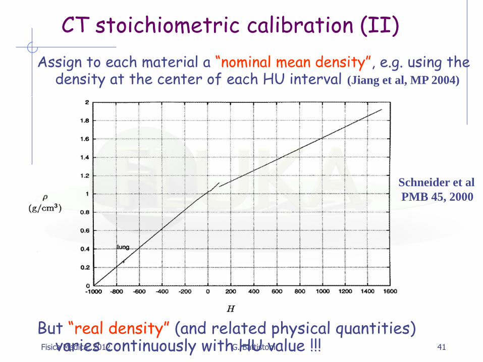
CT stoichiometric calibration (II)
Assign to each material a “nominal mean density”, e.g. using the density at the center of each HU interval (Jiang et al, MP 2004)
Schneider et al
PMB 45, 2000
But “real density” (and related physical quantities) varies continuously with HU value !!!
Fisica Medica, 2012 41 G. Battistoni

Rasterscan Method @ GSI / HIT
scanning of
focussed
ion beams
in fast
dipole magnets
active variation
of the energy,
focus and
intensity in the
accelerator and
beam lines
Haberer et al., NIM A , 1993
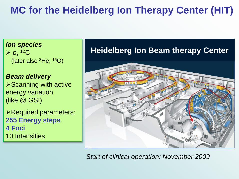
Start of clinical operation: November 2009
Heidelberg Ion Beam therapy Center
MC for the Heidelberg Ion Therapy Center (HIT)
Ion species
p, 12C
(later also 3He, 16O)
Beam delivery
Scanning with active
energy variation
(like @ GSI)
Required parameters:
255 Energy steps
4 Foci
10 Intensities
Exp. Data (points) from Haettner et al, Rad. Prot. Dos. 2006
Simulation: A. Mairani PhD Thesis, 2007, PMB to be published
Exp. Data (STARS) FLUKA (POINTS - LINE)
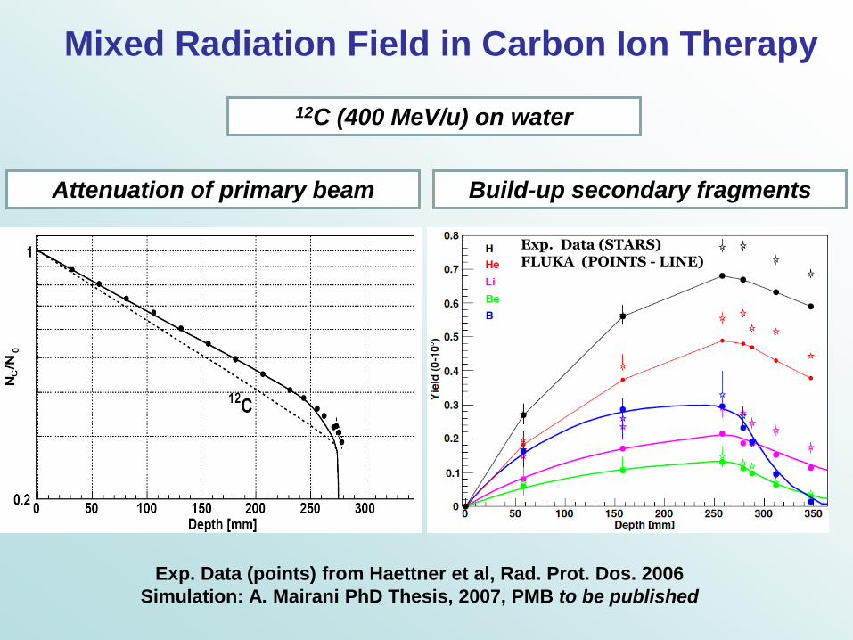
Mixed Radiation Field in Carbon Ion Therapy
12C (400 MeV/u) on water
Attenuation of primary beam Build-up secondary fragments
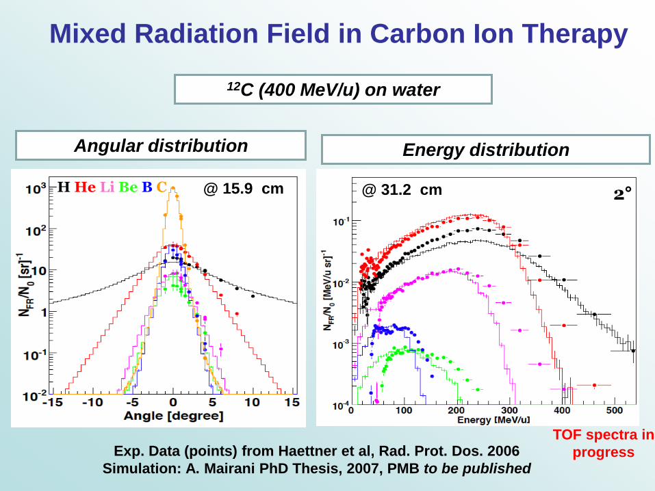
H He Li Be B C @ 15.9 cm 2° @ 31.2 cm
Exp. Data (points) from Haettner et al, Rad. Prot. Dos. 2006
Simulation: A. Mairani PhD Thesis, 2007, PMB to be published
TOF spectra in
progress
Mixed Radiation Field in Carbon Ion Therapy
12C (400 MeV/u) on water
Angular distribution Energy distribution
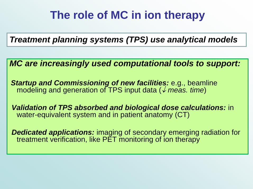
The role of MC in ion therapy
MC are increasingly used computational tools to support:
Startup and Commissioning of new facilities: e.g., beamline
modeling and generation of TPS input data ( meas. time)
Validation of TPS absorbed and biological dose calculations: in water-equivalent system and in patient anatomy (CT)
Dedicated applications: imaging of secondary emerging radiation for treatment verification, like PET monitoring of ion therapy
Treatment planning systems (TPS) use analytical models
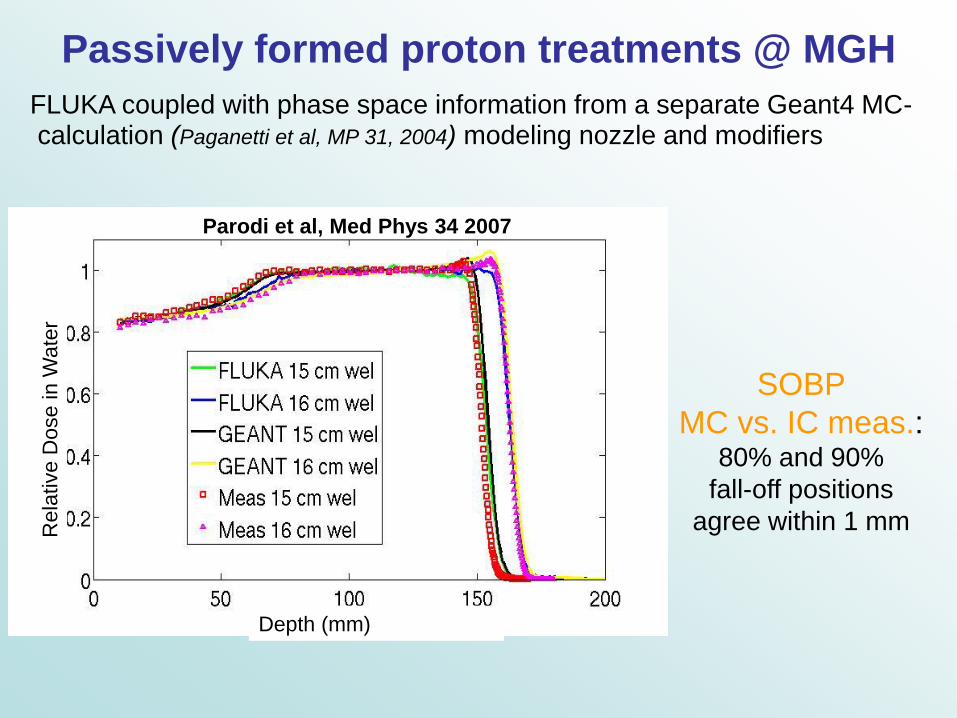
FLUKA coupled with phase space information from a separate Geant4 MC-
calculation (Paganetti et al, MP 31, 2004) modeling nozzle and modifiers
Rela
tive D
ose in W
ate
r
Depth (mm)
Parodi et al, Med Phys 34 2007
SOBP
MC vs. IC meas.: 80% and 90%
fall-off positions
agree within 1 mm
Passively formed proton treatments @ MGH

Start of clinical operation: November 2009
Heidelberg Ion Beam therapy Center
MC for the Heidelberg Ion Therapy Center (HIT)
Ion species
p, 12C
(later also 3He, 16O)
Beam delivery
Scanning with active
energy variation
(like @ GSI)
Required parameters:
255 Energy steps
4 Foci
10 Intensities
12C @ HIT (Nominal focus from FLUKA 2006.3b)
Energy (MeV/u)
Focus (
FW
HM
) in
air @
Isocentr
e
(mm
)
…Taking into account desired 4-10 mm focus @ ISO for higher E
and physical limitation from scattering in monitor system and air
Parodi, Brons, Naumann, Haberer et al, to be published
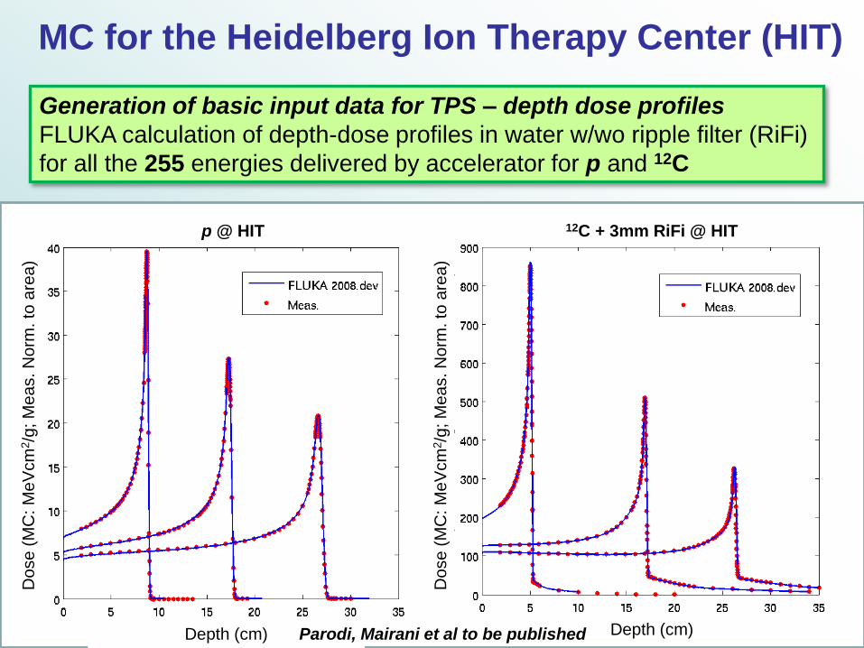
MC for the Heidelberg Ion Therapy Center (HIT)
Generation of basic input data for TPS – depth dose profiles
FLUKA calculation of depth-dose profiles in water w/wo ripple filter (RiFi)
for all the 255 energies delivered by accelerator for p and 12C
Depth (cm) Depth (cm) Parodi, Mairani et al to be published
Do
se
(M
C: M
eV
cm
2/g
; M
ea
s. N
orm
. to
are
a)
Do
se
(M
C: M
eV
cm
2/g
; M
ea
s. N
orm
. to
are
a)
p @ HIT 12C + 3mm RiFi @ HIT
MC for the Heidelberg Ion Therapy Center (HIT)
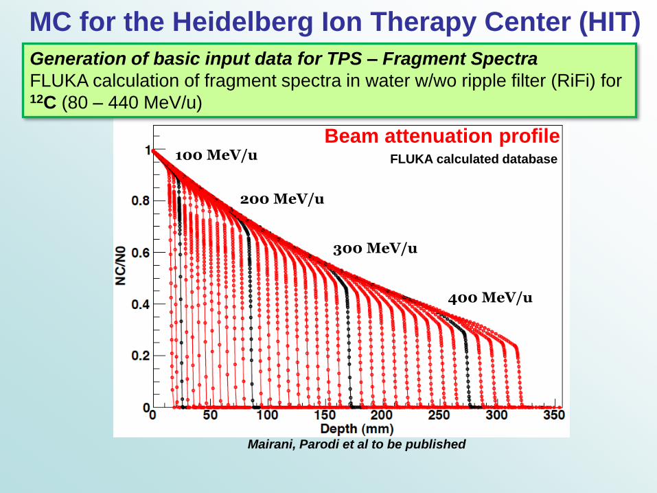
100 MeV/u
200 MeV/u
300 MeV/u
400 MeV/u
FLUKA calculated database
Generation of basic input data for TPS – Fragment Spectra
FLUKA calculation of fragment spectra in water w/wo ripple filter (RiFi) for 12C (80 – 440 MeV/u)
Beam attenuation profile
Mairani, Parodi et al to be published

MC for the Heidelberg Ion Therapy Center (HIT)
FLUKA calculated database
Generation of basic input data for TPS – Fragment Spectra
FLUKA calculation of fragment spectra in water w/wo ripple filter (RiFi) for 12C (80 – 440 MeV/u)
12C ions (400 MeV/u) - Energy Spectra at 25 cm
Mairani, Parodi et al to be published
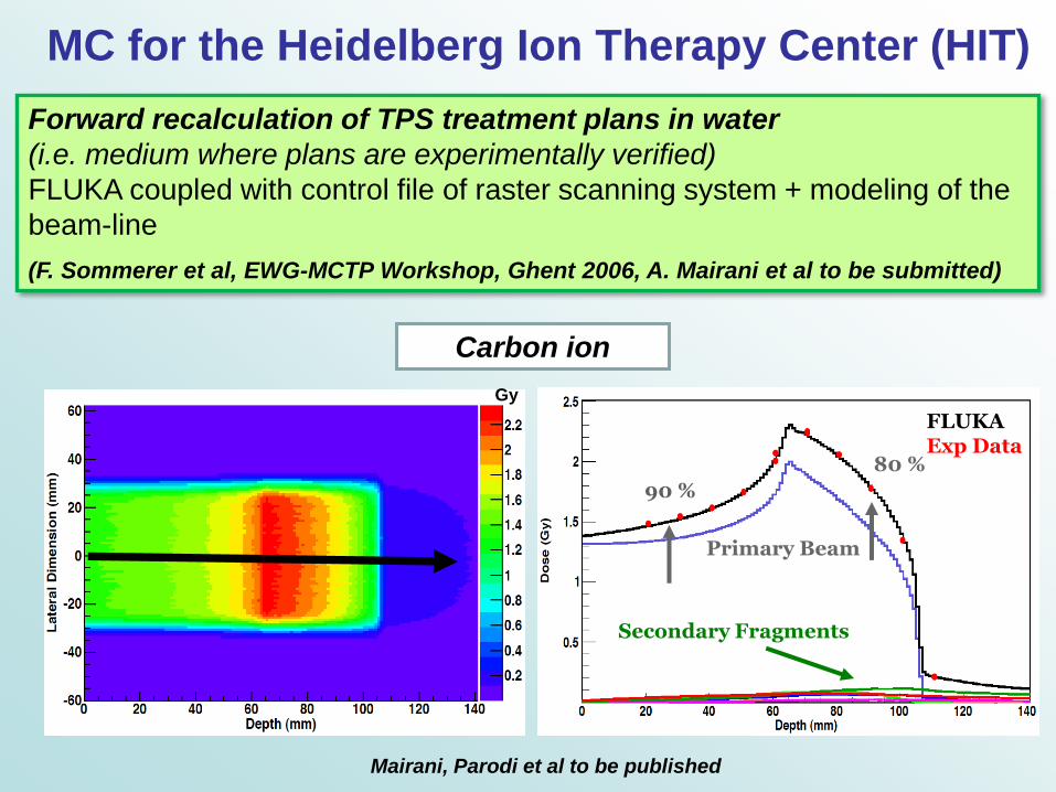
MC for the Heidelberg Ion Therapy Center (HIT)
Forward recalculation of TPS treatment plans in water
(i.e. medium where plans are experimentally verified)
FLUKA coupled with control file of raster scanning system + modeling of the
beam-line
(F. Sommerer et al, EWG-MCTP Workshop, Ghent 2006, A. Mairani et al to be submitted)
Gy
Primary Beam
FLUKA Exp Data
90 %
80 %
Secondary Fragments
Mairani, Parodi et al to be published
Carbon ion

MC for the Heidelberg Ion Therapy Center (HIT)
Forward recalculation of TPS treatment plans in water
Gy 30 mm 70 mm 110 mm
FLUKA Exp Data
110 mm 70 mm 30 mm
Primary Beam H He Li Be B C
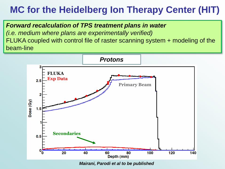
MC for the Heidelberg Ion Therapy Center (HIT)
Forward recalculation of TPS treatment plans in water
(i.e. medium where plans are experimentally verified)
FLUKA coupled with control file of raster scanning system + modeling of the
beam-line
Mairani, Parodi et al to be published
Protons
Primary Beam
FLUKA Exp Data
Secondaries
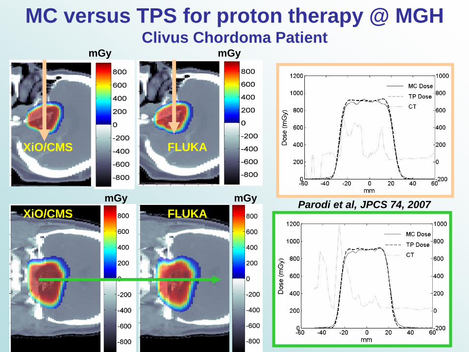
XiO/CMS FLUKA
mGy mGy
MC versus TPS for proton therapy @ MGH Clivus Chordoma Patient
FLUKA XiO/CMS
mGy mGy
Parodi et al, JPCS 74, 2007
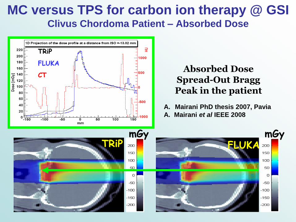
FLUKA
TRiP
FLUKA
CT
mGy mGy
Absorbed Dose Spread-Out Bragg Peak in the patient
A. Mairani PhD thesis 2007, Pavia
A. Mairani et al IEEE 2008
TRiP
MC versus TPS for carbon ion therapy @ GSI Clivus Chordoma Patient – Absorbed Dose

Biological MC calculations:
FLUKA coupled with external bio database
Biaggi et al NIM B 159, 1999
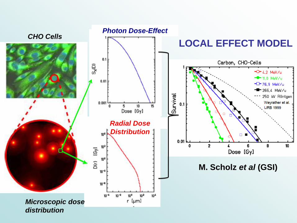
M. Scholz et al (GSI)
Microscopic dose
distribution
CHO Cells
Radial Dose
Distribution
Photon Dose-Effect
LOCAL EFFECT MODEL

PMB 51 (2006) 1959 M. Krämer and M. Scholz
Starting from the intrinsic LEM coefficients, the αD and βD parameters are
obtained in terms of macroscopic dose applying the “rapid approach”
described in :
The coupling of the LEM with FLUKA has been carried out using the
Theory of Dual Radiation Action (TDRA) (A. M. Kellerer and H. H. Rossi,
Radiat. Res. 75 (1978) 471):
a biological system exposed to more than one radiation type will show
synergism, implying that the total number of lesions is larger than the
sum of the lesions produced by each single beam component, due to
interactions between sub-lesions produced by different components.
A. Mairani et al, IEEE 2008 and PMB 2010 submitted
Biological MC calculations:
FLUKA coupled with the Local Effect Model
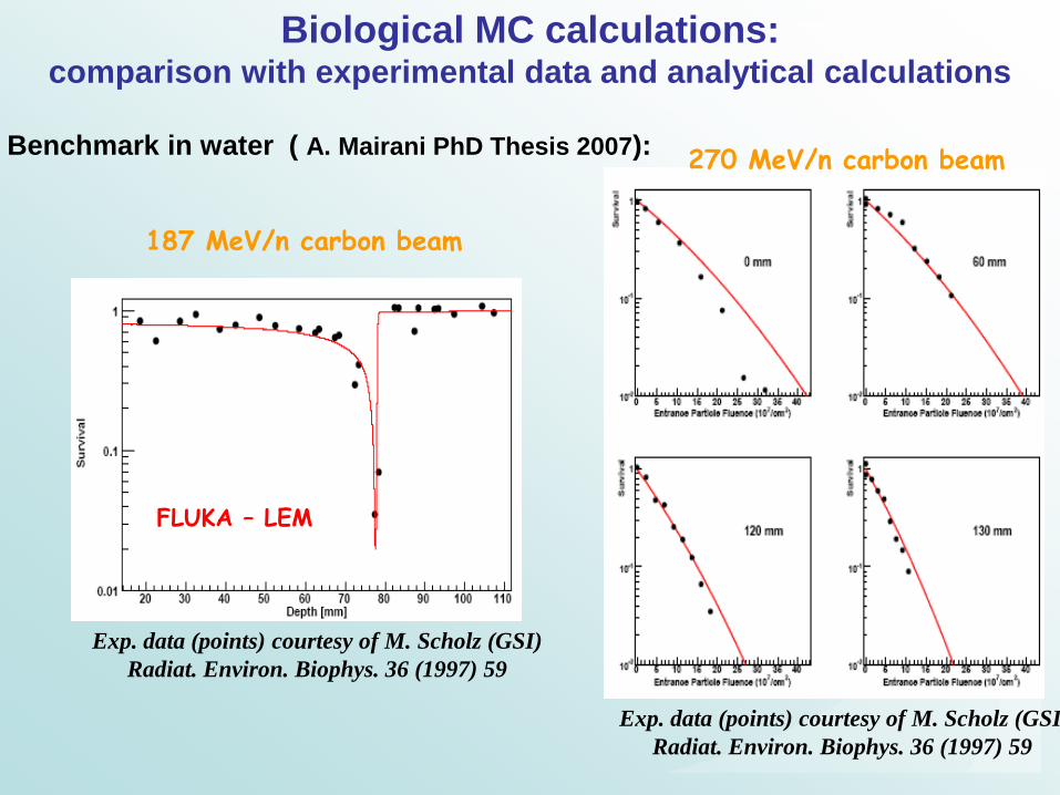
Benchmark in water ( A. Mairani PhD Thesis 2007):
Biological MC calculations: comparison with experimental data and analytical calculations
Exp. data (points) courtesy of M. Scholz (GSI)
Radiat. Environ. Biophys. 36 (1997) 59
270 MeV/n carbon beam
Exp. data (points) courtesy of M. Scholz (GSI)
Radiat. Environ. Biophys. 36 (1997) 59
187 MeV/n carbon beam
FLUKA – LEM

Exp. Data and analytical calculations: Krämer et al, PMB 48 (2003) 2063
MC Calculations: A. Mairani et al, PMB 2010 submitted
Clinical calculation:
Two opposing dose ramps with tissue sparing (as brain-stem)
TRiP98 Analytical calculations: biological planning and optimization for
CHO cells
FLUKA-LEM: forward calculation of the optimized plan
Biological MC calculations: comparison with experimental data and analytical calculations
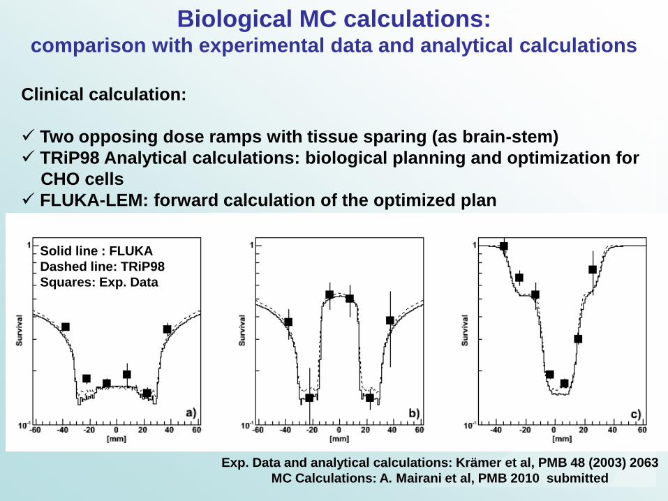
Solid line : FLUKA
Dashed line: TRiP98
Squares: Exp. Data

mGyE
mGyE FLUKA - LEM
TRiP
A. Mairani et al, to be published
TRiP mGy
mGy FLUKA
MC versus TPS for carbon ion therapy @ GSI Clivus Chordoma Patient – Absorbed/Biological Dose

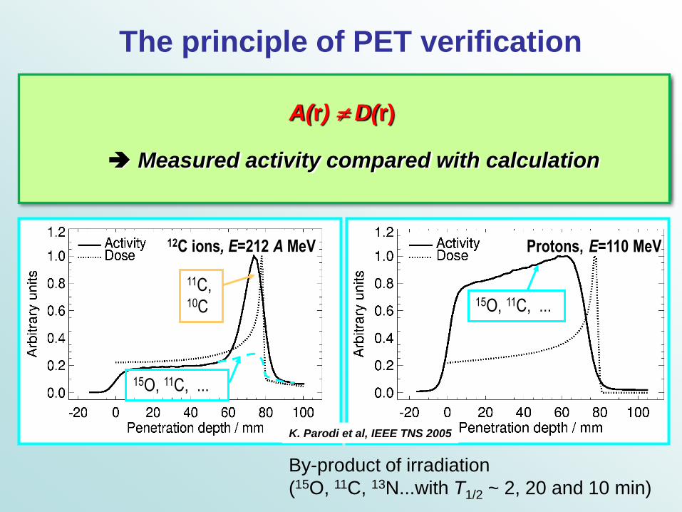
The principle of PET verification
Before collision After collision
Proton
Target fragment
Proton
Atomic nucleus
of tissue
16 O 15O Neutron
Before collision After collision Projectile
fragment
Target fragment
Projectile 12C ion
Atomic nucleus of tissue
16 O 15O Neutrons
C 12 11 C
Protons, E=110 MeV
15O, 11C, ...
12C ions, E=212 A MeV
11C, 10C
15O, 11C, ...
K. Parodi et al, IEEE TNS 2005
By-product of irradiation
(15O, 11C, 13N...with T1/2 ~ 2, 20 and 10 min)
The principle of PET verification
Before collision After collision
Proton
Target fragment
Proton
Atomic nucleus
of tissue
16 O 15O Neutron
Before collision After collision Projectile
fragment
Target fragment
Projectile 12C ion
Atomic nucleus of tissue
16 O 15O Neutrons
C 12 11 C
Protons, E=110 MeV
15O, 11C, ...
A(r) D(r)
Measured activity compared with calculation
12C ions, E=212 A MeV
11C, 10C
15O, 11C, ...
K. Parodi et al, IEEE TNS 2005
By-product of irradiation
(15O, 11C, 13N...with T1/2 ~ 2, 20 and 10 min)

FLUKA Monte Carlo code using
Field-specific beam source information from Geant4 modeling of the nozzle and beam modifiers (Paganetti et al, MP 31, 2004)
Planning CT (segmented into 27 material) and same CT-range calibration curve as TPS (Parodi et al MP 34, 2007, PMB 52, 2007)
Experimental cross-sections for +-emitter production
Calculation model of +-activation
Semi-empirical biological modeling (Parodi et al IJROBP 2007)
Convolution with 3D Gaussian kernel (7-7.5 mm FWHM)
Data from IAEA Nuclear Data Section
…and other reaction channels on N, O, Ca
yielding, e.g., 13N, 38K, …
(Parodi et al, PMB 45, 2002, Parodi et al, PMB 52, 2007)
G. Battistoni
67
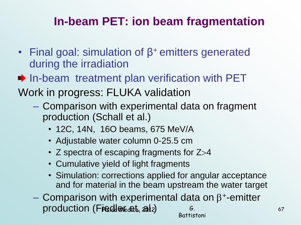
In-beam PET: ion beam fragmentation
• Final goal: simulation of β+ emitters generated during the irradiation
In-beam treatment plan verification with PET
Work in progress: FLUKA validation
– Comparison with experimental data on fragment production (Schall et al.)
• 12C, 14N, 16O beams, 675 MeV/A
• Adjustable water column 0-25.5 cm
• Z spectra of escaping fragments for Z4
• Cumulative yield of light fragments
• Simulation: corrections applied for angular acceptance and for material in the beam upstream the water target
– Comparison with experimental data on +-emitter production (Fiedler et. al.) Fisica Medica, 2012
G. Battistoni
68
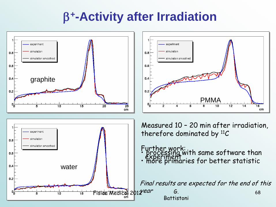
+-Activity after Irradiation
water
PMMA
graphite
Measured 10 – 20 min after irradiation, therefore dominated by 11C
Further work: • processing with same software than experiment • more primaries for better statistic
Final results are expected for the end of this year Fisica Medica, 2012

Both the data and the FLUKA calculations are normalized
to the same area
Backprojections: FLUKA vs Exp data
12C 260 MeV/A on PMMA, simulated relative production rate of
different isotopes
12C 260 MeV/A on PMMA
F. Sommerer PhD Thesis, 2007, F. Sommerer et al PMB 54 2009
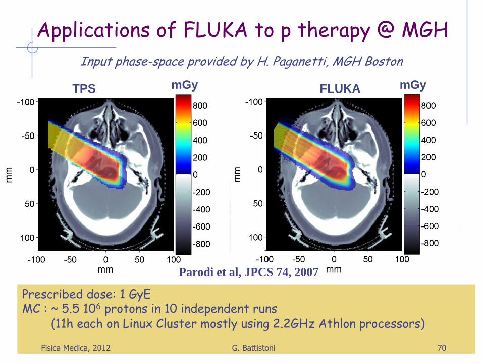
Applications of FLUKA to p therapy @ MGH
TPS FLUKA
Prescribed dose: 1 GyE MC : ~ 5.5 106 protons in 10 independent runs (11h each on Linux Cluster mostly using 2.2GHz Athlon processors)
Parodi et al, JPCS 74, 2007
mGy mGy
Input phase-space provided by H. Paganetti, MGH Boston
Fisica Medica, 2012 70 G. Battistoni
TPS FLUKA
mGy mGy
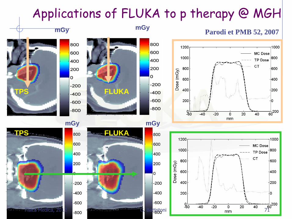
Applications of FLUKA to p therapy @ MGH
FLUKA TPS
mGy mGy Parodi et PMB 52, 2007
Fisica Medica, 2012 71 G. Battistoni

FLUKA mGy
Prescribed dose: 2 GyE
MC : ~ 7.4 107p in 12 independent runs
(~ 130h each on 2.2 GHz Linux cluster)
TPS
metallic
implants
K. Parodi et al, IJROBP 2007
mGy
Applications of FLUKA
to p therapy @ MGH
Fisica Medica, 2012 72 G. Battistoni
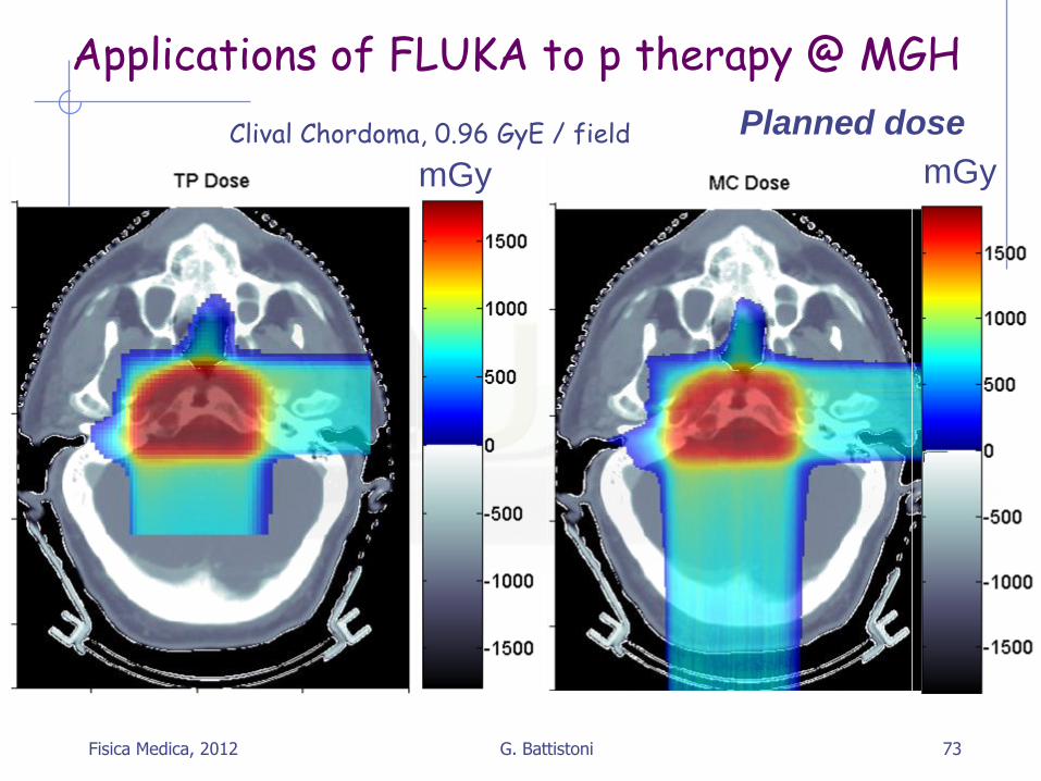
Applications of FLUKA to p therapy @ MGH
mGy mGy Clival Chordoma, 0.96 GyE / field Planned dose
Fisica Medica, 2012 73 G. Battistoni
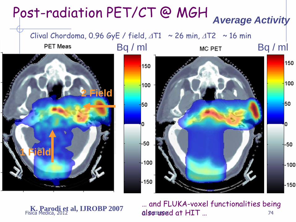
Post-radiation PET/CT @ MGH
Clival Chordoma, 0.96 GyE / field, T1 ~ 26 min, T2 ~ 16 min
Bq / ml Bq / ml
Average Activity
1 Field
2 Field
K. Parodi et al, IJROBP 2007 … and FLUKA-voxel functionalities being also used at HIT … Fisica Medica, 2012 74 G. Battistoni

β+ emitters for ion beams: phantom experiments
Application of FLUKA to PET monitoring of ion species (e.g. 12C, 16O) based on internal nuclear models
Simulation of imaging process (β+-decay, propagation of e+ and annihilation photons, detection) same as for measured data Exact replica of the experimental setup, PET heads included FLUKA irradiation+decay features exploited MC γ’s reaching PET heads converted to list-mode data by modified PETSIM1
Backprojection with same routines as in experiment
In-beam PET @ GSI 260 MeV/u 12C ion on Graphite, backprojections
FLUKA Measurement
F. Sommerer PhD Thesis, 2007, F. Sommerer et al PMB 54 2009
1Pönisch et al. PMB 49 2004
Fisica Medica, 2012 75 G. Battistoni

END
76 Fisica Medica, 2012 G. Battistoni


![FLUKA Advanced Scoring · 2010-10-06 · Reaction Rate and Cross Section[3/3] 6 •Dividing the macroscopic cross section by N 0, the number of atoms per unit volume, one obtains](https://static.documents.pub/doc/80x56/5f3a8793f02d8a6b4c61ac20/fluka-advanced-scoring-2010-10-06-reaction-rate-and-cross-section33-6-adividing.jpg)
