60
MEDICAL OXYGEN PLANT PSA- TECHNOLOGY SPECIFICATION GUIDELINE Medical Grade Oxygen Plant January 2018 Addis Ababa, Ethiopia

MEDICAL OXYGEN PLANT PSA-TECHNOLOGY SPECIFICATION
GUIDELINE Medical Grade Oxygen Plant
January 2018
Addis Ababa, Ethiopia
PSA Oxygen Generating Plant & Distribution Technical Specifications
1
Table of contents
Contents Page Table of contents ....................................................................................................................... 1
List of Tables ............................................................................................................................. 3
Foreword ..................................................................................................................................... 4
The Scope of the Document and How to use it ................................................................................. 6
Acknowledgments ........................................................................................................................ 9
List of Participants .......................................................................................................................10
Acronyms ...................................................................................................................................11
Introduction ................................................................................................................................12
Description of Function .................................................................................................................13
Section 1: Scope of Technical Specifications ....................................................................................13
Section 2: Plant Design and Layout .................................................................................................14
2.1 General ........................................................................................................................14
2.2 Siting............................................................................................................................15
2.3 Structural .....................................................................................................................16
2.3.1 Ventilation& Air Circulation/Conditioning ..................................................................16
2.3.2 Lighting .................................................................................................................16
2.3.3 Noise Control .........................................................................................................17
2.3.4 Labelling/signage ....................................................................................................17
Section 3: Oxygen generation Plant ................................................................................................18
3.1 Air Intake & Compression Unit ........................................................................................19
3.1.1 Feed Air compressor ...............................................................................................19
3.1.2 Dryer ....................................................................................................................20
3.1.3 Filters ....................................................................................................................21
3.1.4 Air receiver tank .....................................................................................................22
3.2 PSA/Oxygen generator unit .............................................................................................22
3.2.1 PSA Vessels ............................................................................................................24
3.2.2 Molecular Sieve Units ..............................................................................................24
3.2.3 Oxygen receiver/buffer tank ....................................................................................24
3.2.4 PSA Operations ......................................................................................................25
3.3 Oxygen booster compressor (oil-free) ..............................................................................25
3.3.1 Supplemental Cylinder Filling Manifold ......................................................................26
Section 4: Distribution Manifolds ...................................................................................................28
4.1 General ........................................................................................................................28
4.1.1 Location of and access to manifold rooms .................................................................28
4.1.2 Construction and layout of manifold rooms ...............................................................29
4.1.3 Manifold component specifications ..........................................................................29
4.2 Primary supply system ....................................................................................................30

PSA Oxygen Generating Plant & Distribution Technical Specifications
2
4.2.1 Pressure control .....................................................................................................31
4.2.2 Power supply interruptions ......................................................................................32
4.3 Secondary source supply system......................................................................................33
Section 5: Pipelines ...................................................................................................................33
Section 6: Plant control, monitoring and indicating systems ..............................................................35
6.1 General ........................................................................................................................35
6.2 Plant Control and Indication Unit .....................................................................................36
6.3 Oxygen Monitoring System .............................................................................................37
6.3.1 Compressor and vacuum starter units .......................................................................37
6.3.2 Molecular sieve control unit .....................................................................................38
6.4 Plant status monitoring ..................................................................................................38
6.4.1 Plant status indicator unit ........................................................................................39
6.5 Manifold monitoring and indicating system .......................................................................40
6.5.1 Manifold monitoring ...............................................................................................41
6.5.2 Manifold indicator unit ............................................................................................41
6.6 Warning & Alarm Systems...............................................................................................41
6.6.1 Alarm signal status unit- Plant ..................................................................................42
6.6.2 Alarm signal status unit - Manifold ............................................................................43
6.6.3 Visual signals ..........................................................................................................44
6.6.4 Audible signals .......................................................................................................44
6.6.5 Temporary muting ..................................................................................................44
6.6.6 Continuous muting .................................................................................................44
Section 7: Electrical for controls ..................................................................................................45
7.1 General ........................................................................................................................45
Operating Environment .............................................................................................................45
7.2 System integrity ............................................................................................................45
7.2.1 Safety extra low voltage/functional extra low voltage power supply ..............................46
7.3 Warning and alarm system faults .....................................................................................46
7.3.1 Line fault ...............................................................................................................46
7.3.2 Communication/wiring fault.....................................................................................47
7.3.3 Mains power failure ................................................................................................47
7.3.4 Standby battery ......................................................................................................47
Standards and Safety Requirements ............................................................................................47
Section 8: Validation & Verification .............................................................................................47
8.1 Prior to shipment ...........................................................................................................48
8.2 After installation in-country ............................................................................................49
8.3 Program of tests and checks............................................................................................49
8.3.1 General .................................................................................................................50
8.3.2 Pipeline carcass ......................................................................................................51
8.3.3 Pipeline system ......................................................................................................52
8.3.4 Quality Assurance / Quality Control ...........................................................................53
8.3.5 Labelling, marking and signage: ................................................................................54
PSA Oxygen Generating Plant & Distribution Technical Specifications
3
Section 9: Training of Plant operators and Hospital staff ...................................................................54
Section 10: Documentation required ..............................................................................................55
Section 11: Guarantees/Warranty ..................................................................................................55
Section 12: Maintenance ..............................................................................................................55
Annex 1 – Standards Referenced ...................................................................................................57
Annex 2 - Testing and commissioning decision tree ..........................................................................59
List of Tables
Table 1 List of Participants and organization represented ......................................................................... 10
Table 2 Overarching specifications of Pressure Swing Adsorption (PSA) oxygen Plant and requisite components ................................................................................................................................................ 14
Table 3 Labelling and signs for medical gas system .................................................................................... 17
Table 4 Components and standards for oxygen quality ............................................................................. 53
PSA Oxygen Generating Plant & Distribution Technical Specifications
4
Foreword
Hypoxemia, below thenormal level of oxygen in tissue, is commonly associated with
mortality in developing countries, yet feasible and cost-effective ways to address hypoxemia
receive little attention in current global health strategy. The ability to detect and treat
hypoxemia is critical for patient care and quality of services, especially for children and
neonates. As a life-saving medicine, oxygen should be available at all hospitals and most
health centers (HCs). Oxygen is vital to combat pneumonia-relatedunder-five children
mortality and morbidity and for the treatment of many emergencies, including cardiac
arrest, acute blood loss, shock, dyspnea (breathlessness), pulmonary edema,
unconsciousness, convulsions (eclampsia), and fetal distress during labor. It is also included
in the World Health Organization (WHO) list of essential medicines.
The FMOH in its five years Health Sector Transformation Plan (HSTP) prioritized improving
equitable access to quality health services to all segments of the country. To realize this
transformational agenda, the ministry devised multiple initiatives including Newborn and
Child Survival Strategy, Maternal and Neonatal Health (MNH) road map, Saving Lives
Through Safe Surgery (SaLTS) initiative, theestablishment of trauma centers, strengthening
of emergency medical services and expansion of ICU services. All these initiatives and
services require sustained and adequate availability of oxygen. Furthermore, there are also
initiatives by the FMoH and RHBs to improve O2 facilities including procurement and
distribution of cylinders to health centers and more recently establishment of O2 Plants in
some referral hospitals.
Despite these efforts, the majority of health facilities, health centers, in particular, have
limited availability and functionality of O2 and pulse oximeter. Moreover, the current oxygen
production is not adequate and Plant distribution is concentrated in few areas. Besides, the
oxygen demand will continue to increase significantly over next five years with more
facilities to be built and starting providing service. Additionally, demand for on-site oxygen
generation solutions continues to rise across a number of facilities. Based on recent

PSA Oxygen Generating Plant & Distribution Technical Specifications
5
quantification exercise, at current occupancy, Ethiopia would need 234,000 M3 per month
(~1240 cylinders/day) by end of 2017 to fulfill its oxygen requirement with nearly 10% being
driven by child/neonatal consumption to fulfill its oxygen requirement by Fiscal Year
Cognizant of these challenges and demands,the Federal Ministry of Health (FMOH) has
developed and launched a national medical oxygen and pulse oximeter scale up road map
which provides guidance, and support to all relevant authorities, in order to increase
manufacturing capacity at national level.
According to the roadmap, oxygen Plants for medical gas need to be built in 13 selected referral
and university hospitals with a centrally planned and guided procurement process to ensure
high-quality and sustainable equipment. To realize these efforts and avail quality and
sustainability of equipment a standard procurement and specification guideline is avital step.
Hence,the FMoH has developed this specification guidelineto standardized oxygen
Plantsspecification which will be procured and installed from now onwards in Ethiopia public
hospitals.
Therefore, the FMoH urges all care providers and implementing partners to refer this
specification guideline in order to procure/institute quality and standard equipment.
Name and Title
The Federal Democratic Republic of Ethiopia
PSA Oxygen Generating Plant & Distribution Technical Specifications
6
The Scope of the Document and How to use it
In the absence of an internationally accepted standard for Pressure Swing Adsorption (PSA)
oxygen Plants, this document can be used as a tool by which to help standardize proposed
Plants, for assurance of component completeness, and/or for tender guidance and/or
evaluation. In its current state:
This is not a tender document
This is not a contract document
Use of this document for tender or contract documents will require revisions and modifications
by owner. All variables requiring input have been highlighted in yellow.
There are components of this document that might not apply across all cases, and therefore can
be removed (e.g. decisions might be taken to not install distribution manifolds and using
cylinders directly in the ward might be the choice taken). This document also includes
components that go beyond Plant procurement (e.g., structural requirements of the host
facility).
Furthermore, in terms of language, “should/shall” is to be interpreted as a recommendation,
whereas “must” is to be interpreted as a mandatory requirement.
Sizing and design for all Plants should take into consideration the following points:
Needs assessment / determining O2 demand
When conducting a needs assessment for sizing a Plant, a comprehensive review of historical
medical data is to be conducted and current oxygen demands must be evaluated and quantified,
allowances should be made for an increase in the use of O2/changes to the gas demands caused
by local developments and strategic issues. A review of similar sites with existing Plants should
also be made. It should be noted that higher consumption could be expected when for
PSA Oxygen Generating Plant & Distribution Technical Specifications
7
examplehigh numbers (>20) of CPAP machines are in frequent use (>40 hours/week). Future
plans and/or expected growth shall be taken into consideration.
In addition, mapping of nearby facilities or of the referral catchment of the hospital can also give
an indication of additional needs should the facility consider the sale and distribution of oxygen
cylinders outside of the facility.
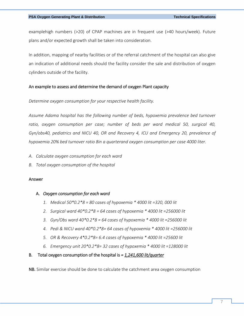
An example to assess and determine the demand of oxygen Plant capacity
Determine oxygen consumption for your respective health facility.
Assume Adama hospital has the following number of beds, hypoxemia prevalence bed turnover
ratio, oxygen consumption per case; number of beds per ward medical 50, surgical 40,
Gyn/obs40, pediatrics and NICU 40, OR and Recovery 4, ICU and Emergency 20, prevalence of
hypoxemia 20% bed turnover ratio 8in a quarterand oxygen consumption per case 4000 liter.
A. Calculate oxygen consumption for each ward
B. Total oxygen consumption of the hospital
Answer
A. Oxygen consumption for each ward
1. Medical 50*0.2*8 = 80 cases of hypoxemia * 4000 lit =320, 000 lit
2. Surgical ward 40*0.2*8 = 64 cases of hypoxemia * 4000 lit =256000 lit
3. Gyn/Obs ward 40*0.2*8 = 64 cases of hypoxemia * 4000 lit =256000 lit
4. Pedi & NICU ward 40*0.2*8= 64 cases of hypoxemia * 4000 lit =256000 lit
5. OR & Recovery 4*0.2*8= 6.4 cases of hypoxemia * 4000 lit =25600 lit
6. Emergency unit 20*0.2*8= 32 cases of hypoxemia * 4000 lit =128000 lit
B. Total oxygen consumption of the hospital is = 1,241,600 lit/quarter
NB. Similar exercise should be done to calculate the catchment area oxygen consumption
PSA Oxygen Generating Plant & Distribution Technical Specifications
8
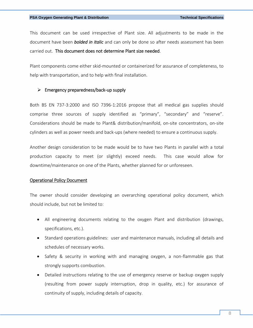
This document can be used irrespective of Plant size. All adjustments to be made in the
document have been bolded in italic and can only be done so after needs assessment has been
carried out. This document does not determine Plant size needed.
Plant components come either skid-mounted or containerized for assurance of completeness, to
help with transportation, and to help with final installation.
Emergency preparedness/back-up supply
Both BS EN 737-3:2000 and ISO 7396-1:2016 propose that all medical gas supplies should
comprise three sources of supply identified as “primary”, “secondary” and “reserve”.
Considerations should be made to Plant& distribution/manifold, on-site concentrators, on-site
cylinders as well as power needs and back-ups (where needed) to ensure a continuous supply.
Another design consideration to be made would be to have two Plants in parallel with a total
production capacity to meet (or slightly) exceed needs. This case would allow for
downtime/maintenance on one of the Plants, whether planned for or unforeseen.
Operational Policy Document
The owner should consider developing an overarching operational policy document, which
should include, but not be limited to:
All engineering documents relating to the oxygen Plant and distribution (drawings,
specifications, etc.).
Standard operations guidelines: user and maintenance manuals, including all details and
schedules of necessary works.
Safety & security in working with and managing oxygen, a non-flammable gas that
strongly supports combustion.
Detailed instructions relating to the use of emergency reserve or backup oxygen supply
(resulting from power supply interruption, drop in quality, etc.) for assurance of
continuity of supply, including details of capacity.
PSA Oxygen Generating Plant & Distribution Technical Specifications
9
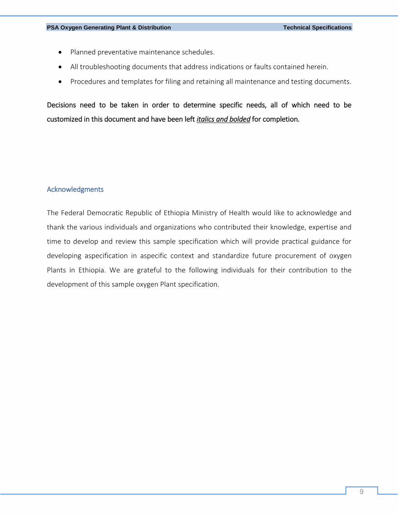
Planned preventative maintenance schedules.
All troubleshooting documents that address indications or faults contained herein.
Procedures and templates for filing and retaining all maintenance and testing documents.
Decisions need to be taken in order to determine specific needs, all of which need to be
customized in this document and have been left italics and bolded for completion.
Acknowledgments
The Federal Democratic Republic of Ethiopia Ministry of Health would like to acknowledge and
thank the various individuals and organizations who contributed their knowledge, expertise and
time to develop and review this sample specification which will provide practical guidance for
developing aspecification in aspecific context and standardize future procurement of oxygen
Plants in Ethiopia. We are grateful to the following individuals for their contribution to the
development of this sample oxygen Plant specification.

PSA Oxygen Generating Plant & Distribution Technical Specifications
10
List of Participants
Table 1 List of Participants and organization represented
S.No Name Organization
1 Alemu Abibi FMOH
2 Asfaw Afework FMOH
3 AndualemWube Addis Ababa RHB
4 Walta Teklu PFAS
5 Demoz Kebede FMHACA
6 Betegiabher Ayele SNNP RHB
7 NatnaelAtsbeha Addis Ababa/Private
8 Hailu Kebede FMOH
9 Dr. Simret Amaha FMOH
10 Mulugeta Mideksa Clinton Health Access Initiative (CHAI)
11 Alemayehu Berhanu Clinton Health Access Initiative (CHAI)
PSA Oxygen Generating Plant & Distribution Technical Specifications
11
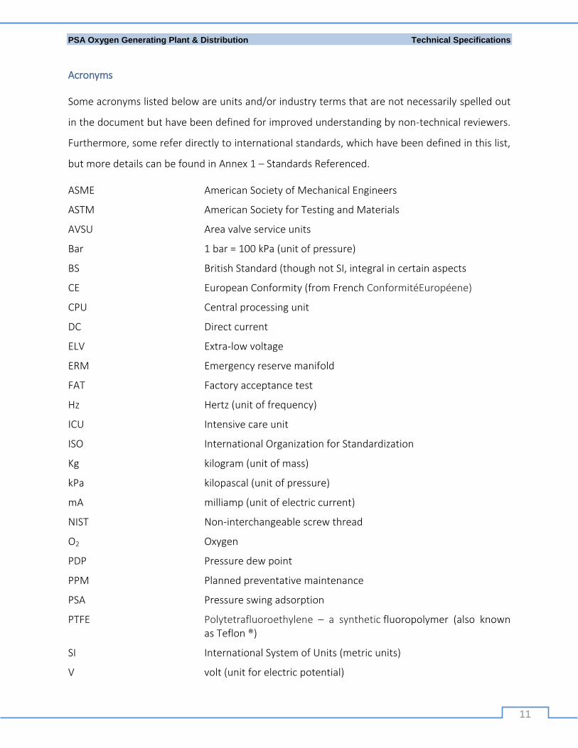
Acronyms
Some acronyms listed below are units and/or industry terms that are not necessarily spelled out
in the document but have been defined for improved understanding by non-technical reviewers.
Furthermore, some refer directly to international standards, which have been defined in this list,
but more details can be found in Annex 1 – Standards Referenced.
ASME American Society of Mechanical Engineers
ASTM American Society for Testing and Materials
AVSU Area valve service units
Bar 1 bar = 100 kPa (unit of pressure)
BS British Standard (though not SI, integral in certain aspects
CE European Conformity (from French ConformitéEuropéene)
CPU Central processing unit
DC Direct current
ELV Extra-low voltage
ERM Emergency reserve manifold
FAT Factory acceptance test
Hz Hertz (unit of frequency)
ICU Intensive care unit
ISO International Organization for Standardization
Kg kilogram (unit of mass)
kPa kilopascal (unit of pressure)
mA milliamp (unit of electric current)
NIST Non-interchangeable screw thread
O2 Oxygen
PDP Pressure dew point
PPM Planned preventative maintenance
PSA Pressure swing adsorption
PTFE Polytetrafluoroethylene – a synthetic fluoropolymer (also known as Teflon ®)
SI International System of Units (metric units)
V volt (unit for electric potential)
PSA Oxygen Generating Plant & Distribution Technical Specifications
12
Introduction
As a life-saving medicine, oxygen should be available in all hospitals and health centers (HCs).
Oxygen is vital to reduce mortality and morbidity from cardiac arrest, acute blood loss, shock,
dyspnea (breathlessness), pulmonary edema, pneumonia, unconsciousness, convulsions
(eclampsia), and fetal distress during labor.
Currently, Oxygen availability varied widely across regions, and between facility types (hospitals
Vs health centers) in Ethiopia. Oxygen availability was generally higher at the hospital level.
From the recent assessment in December, 2016, only 3% of health centers and 26% of hospitals
have regular practice of oxygen consumption and stock monitoring mechanism, while 9% of
health centers and 47% of hospitals think there are enough refilling sources for oxygen, which
shows a need to expand supply base for oxygen supply both for health centers and hospitals.
Having an appropriate supply monitoring practice and timely refilling system is also critical at the
facility level.
Except 3 hospitals already functioning, and a few others under construction, there is no public
oxygen refiling center. The few private medical & non-medical oxygen suppliers are located in
Addis Ababa, in which accessibility is one of the critical challenges so far observed; some health
facilities are supposed to travel more than 800km for refilling.
Moreover, the current oxygen production is not adequate and Plant distribution is concentrated
in few areas. Furthermore, the oxygen demand will continue to increase significantly over next
five years with more facilities to be built and starting providing service.
Additionally, demand for on-site oxygen generation solutions continues to rise across a number
of facilities. Based on recent quantification exercise, at current occupancy, Ethiopia would need
234 K M3 per month (~1240 cylinders/day) by end of 2017 to fulfill its oxygen requirement with
nearly 10% being driven by child/neonatal consumption while it might need close to 1 B liters per
month (equivalent of ~4,700 large cylinders/day) to fulfill its oxygen requirement by Fiscal Year
PSA Oxygen Generating Plant & Distribution Technical Specifications
13
(FY) 2020/21 with expected infrastructure expansion driven by primary hospitals as well as
improved health service utilization.
Recognizing this, the Federal Ministry of Health (FMOH) has developed and launched a national
medical oxygen and pulse oximeter road map which provides guidance, and support to all
relevant authorities, in order to increase manufacturing capacity at national level.
According to the road map, oxygen Plants for medical gas need to be built in 13 selected referral
and university hospitals with a centrally planned and guided procurement process to ensure
high-quality and sustainable equipment. These hospitals will use oxygen for their own
consumption, as well as refill nearby health centers and hospitals with cylinders, or could also
sell to private facilities.
Therefore, this specification is prepared to standardized oxygen Plants which will be procured
and installed from now onwards in Ethiopia public hospitals.
Description of Function
Oxygen Plantconsists of Air compressor with 7.5 bar output pressure, pre-filters, Refrigerator Air
dryer, fine filters, carbon activator filter, Air receiver tanker which 3000 litters, oxygen generator
with purity 93±3% and total output 90-120m3/hr. regulators, valves, control systems, alarms,
high-pressure booster which is a method of boosting oxygen from Oxygen Tanker to filling
station up to 200 Bar and with theinput of 7.5 Bar with flow rate 80m3/hr. (which assume that
2/3rdwill supply to other institution and 1/3rd for their own consumption). The booster can fill
more than 214 type D cylinders in 16 working hours and can supply simultaneously 1/3rd of the
production to the piping system.
Section 1: Scope of Technical Specifications
The Plant under consideration must be able to offer an integrated medical grade oxygen
production and distribution system as described in theses pacifications. Themake and/or model
of the proposed system should have a proven track record in similar operating contexts.

PSA Oxygen Generating Plant & Distribution Technical Specifications
14
The technical specifications for the functionality of the system are prime components for
assurance of appropriate system design and selection;specifications are the operating guidelines
as well as for compliance and certification purposes.Products under considerationmust comply
with the minimum specifications as outlinedherein and listed in Annex 1 or justifiable
equivalents. Plantsmay contain components of mixed national standards (e.g. components from
both Europe and the USA), but compatibilitymust be verified.
Proposed alternate items/components will be considered so long as they also conform to the
defined international standards mentioned herein and are deemed acceptable by the owner,
though these must be clearly indicated.
All dimensions herein are of the International System of Units (SI units), also known as metric
units. Products proposed and delivered must be functional and should have SI units.
Section 2: Plant Design and Layout
2.1 General
(To be completed based on site specifics, initial planning and needs assessment).
Overarching specifications of Pressure Swing Adsorption (PSA) oxygen Plant and requisite
components:
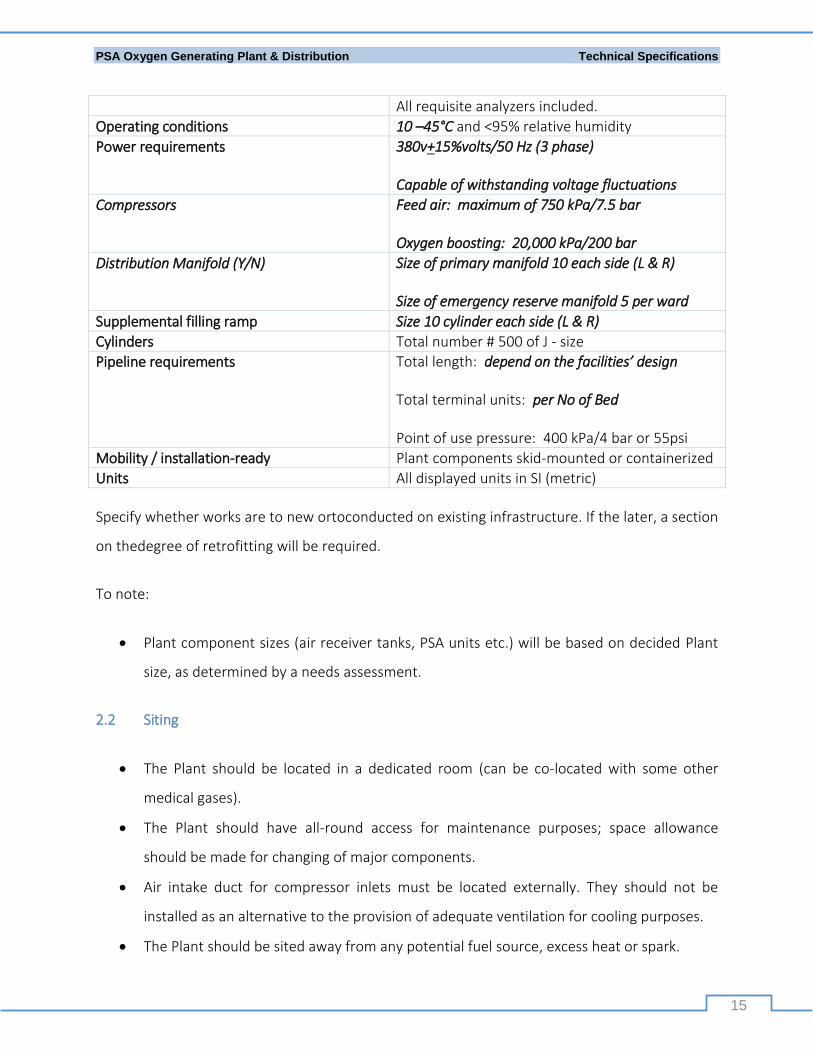
Table 2 Overarching specifications of Pressure Swing Adsorption (PSA) oxygen Plant and requisite components
Component Specification
Plant size: 90-120m3/hr. (The size of the plant is determined by the need assessment of the specific plant)
Pressure swing adsorption technology
Oxygen output quality Purity of 93 ±3%
At elevation of up to 2,500 m above sea level
PSA Oxygen Generating Plant & Distribution Technical Specifications
15
All requisite analyzers included.
Operating conditions 10 –45°C and <95% relative humidity
Power requirements 380v+15%volts/50 Hz (3 phase)
Capable of withstanding voltage fluctuations
Compressors Feed air: maximum of 750 kPa/7.5 bar
Oxygen boosting: 20,000 kPa/200 bar
Distribution Manifold (Y/N) Size of primary manifold 10 each side (L & R)
Size of emergency reserve manifold 5 per ward
Supplemental filling ramp Size 10 cylinder each side (L & R)
Cylinders Total number # 500 of J - size
Pipeline requirements Total length: depend on the facilities’ design
Total terminal units: per No of Bed
Point of use pressure: 400 kPa/4 bar or 55psi
Mobility / installation-ready Plant components skid-mounted or containerized
Units All displayed units in SI (metric)
Specify whether works are to new ortoconducted on existing infrastructure. If the later, a section
on thedegree of retrofitting will be required.
To note:
Plant component sizes (air receiver tanks, PSA units etc.) will be based on decided Plant
size, as determined by a needs assessment.
2.2 Siting
The Plant should be located in a dedicated room (can be co-located with some other
medical gases).
The Plant should have all-round access for maintenance purposes; space allowance
should be made for changing of major components.
Air intake duct for compressor inlets must be located externally. They should not be
installed as an alternative to the provision of adequate ventilation for cooling purposes.
The Plant should be sited away from any potential fuel source, excess heat or spark.
PSA Oxygen Generating Plant & Distribution Technical Specifications
16
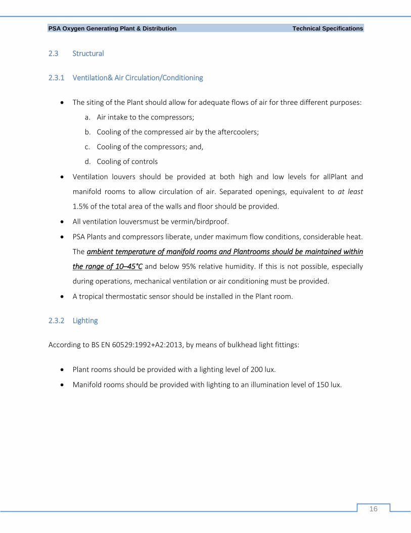
2.3 Structural
2.3.1 Ventilation& Air Circulation/Conditioning
The siting of the Plant should allow for adequate flows of air for three different purposes:
a. Air intake to the compressors;
b. Cooling of the compressed air by the aftercoolers;
c. Cooling of the compressors; and,
d. Cooling of controls
Ventilation louvers should be provided at both high and low levels for allPlant and
manifold rooms to allow circulation of air. Separated openings, equivalent to at least
1.5% of the total area of the walls and floor should be provided.
All ventilation louversmust be vermin/birdproof.
PSA Plants and compressors liberate, under maximum flow conditions, considerable heat.
The ambient temperature of manifold rooms and Plantrooms should be maintained within
the range of 10–45°C and below 95% relative humidity. If this is not possible, especially
during operations, mechanical ventilation or air conditioning must be provided.
A tropical thermostatic sensor should be installed in the Plant room.
2.3.2 Lighting
According to BS EN 60529:1992+A2:2013, by means of bulkhead light fittings:
Plant rooms should be provided with a lighting level of 200 lux.
Manifold rooms should be provided with lighting to an illumination level of 150 lux.
PSA Oxygen Generating Plant & Distribution Technical Specifications
17
2.3.3 Noise Control
Plant rooms should be designed and constructed to ensure adequate control of noise emission.
Size of the Plant will have a direct impact on noise levels. Consideration should be given
to providing acoustic enclosures to reduce the free-field noise levels in noise-sensitive
areas adjacent to Plant rooms so as not to exceed 80 dB.
Acoustic enclosure and/or Plant room design must not inhibit normal cooling functions or
maintenance activities.
Discharge from some vacuum pumps may require silencing.
Compressors and pumps should be affixed to an anti-vibration mounting, where
necessary, to minimize transfer of noise and vibration to the structure of the building.
All pipework and electrical conduits connected to the Plant should be fitted with flexible
connectors where necessary to prevent the transmission of noise and vibration along the
pipelines and conduits. Electrical bonding will be required.
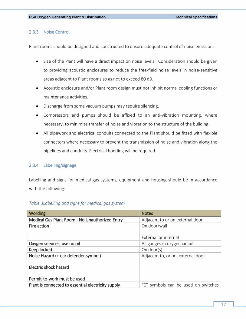
2.3.4 Labelling/signage
Labelling and signs for medical gas systems, equipment and housing should be in accordance
with the following:
Table 3Labelling and signs for medical gas system
Wording Notes
Medical Gas Plant Room - No Unauthorized Entry Adjacent to or on external door
Fire action On door/wall
External or internal
Oxygen services, use no oil All gauges in oxygen circuit
Keep locked On door(s) Noise Hazard (+ ear defender symbol)
Electric shock hazard
Permit-to-work must be used
Adjacent to, or on, external door
Plant is connected to essential electricity supply “E” symbols can be used on switches

PSA Oxygen Generating Plant & Distribution Technical Specifications
18
etc.
Danger 220 volts; Danger 380 volts On Plant/switchgear
Danger rotating machines
Warning: These machines stop and start automatically without warning
Do not isolate without a Permit
Posted adjacent to Plant
Medical air intake “Do not obstruct” On external intakes only
Danger medical gas exhaust or
Danger explosive gases, no smoking, no naked lights
Posted on external wall by discharge pipes
Emergency Tel No
Gas Supplier (if applicable)
Pharmacy number
Plant operator number
External wall
National Occupational Health and Safety Law Internal wall
First aid Internal wall
Cylinder recognition charts, indicating volume (liters of O2) and weight (kg), supplied by the
medical gas supplier, should be prominently displayed as appropriate.
Caution: Oxygen is a non-flammable gas, but strongly supports combustion! A clear safety and
security plan is to be included in an operational policy document.
Section 3: Oxygen generation Plant
The Plant is to deliver 93 ±3% medical-grade oxygen at European or US Pharmacopoeia
monograph quality standards and at a pressure of 400 kPa (4 bar) for piped hospital
oxygen systems or be available for additional compression to fill cylinders.
PSA Oxygen Generating Plant & Distribution Technical Specifications
19
Plant installation should be carried out only by specialist firms registered to BS EN ISO
9001:2000 and BS EN ISO 13485:2016 with the scope of registration appropriately
defined.
3.1 Air Intake & Compression Unit
The air intake and compression unit, including the feed air compressor, dryer, filter bank and air
receiver tank must be mounted on a welded steel skid or containerized.
3.1.1 Feed Air compressor
The air compressor must be manufactured to internationally acceptable standards with
CE mark and/or ISO 9001 certification.
For added supply security, consideration should be given to duplex compressors if the
original design is not two parallel Plants.
Each compressor may require ducting to ensurean adequate flow of cool air. The
operatingtemperature range indicated by the manufacturer should be considered during
system design - refrigeration of the coolingair may need to be provided.
Air compressor should be suitable for both continuous and frequent start/stop
operations at a nominal outlet pressure of 750 kPa (7.5 bar) gauge. It can be of
reciprocating multistage, positive displacement, piston type or oil lubricated rotary screw
type.
Supplied with all accessories for full installation and operation - flywheel, foundation
bolts, motor pulley, v-belts, belt guard, and slide rails for the motor.
Intake air temperature: 10 - 35°C
Gross particle filters down to 1 micron to be placed on the inletside of the compressor.
The compressor must be microprocessor controlled and programmable with the
following minimum features:
i. Automatic control of the operation of the compressor.
ii. Compressor protection by shutting down the compressor or visible alarm lamps
and audible alarm if any of the pre-set values are exceeded.

PSA Oxygen Generating Plant & Distribution Technical Specifications
20
iii. Have a meter to monitor components and running hours ofservice.
iv. Provide automatic restart after voltage failure.
v. Emergency switch to shut down the Plant in case of emergency.
vi. The compressor will have anautomatic load-unload regulation system and
automatic drain.
The compressor must be silenced if needed as indicated in section 2.3.3 Noise Control.
Compressed air output requirements:
o Dry, oil-free and clean compressed air to prevent contaminants entering the
oxygen generator equipment and to protect patients and instruments.
o Volume: Manufacturer rated to suit Plant output design
A multistage oil separator capable of achieving 2 ppm oil carry-over must be fitted to
minimize contamination and maintenance.
Completely enclosed fan-cooled electric motors must be used and incorporate
maintenance-free greased for life bearings.
3.1.2 Dryer
The compressed air dryer must be manufactured to internationally acceptable standards
with CE mark and/or ISO 9001 certification.
The dryer must be of continuous and fully automatic operation with no net air loss.
Supplied with electronic control, communication and monitoring module for pressure
regulation and monitoring in vessels.
The dryer must be sized to dry 100% of the air compressor capacity with minimal power
consumption.
Equipped with safety valves.
Either desiccant or refrigerant-type dryers are acceptable.
Desiccant dryers are usually integrated within the molecular sieves and therefore do not
regenerate independently. In this case, the pressure dew point (PDP) of the compressed
air must not be above -35°C @ 10°C ambient.
PSA Oxygen Generating Plant & Distribution Technical Specifications
21
Refrigerant dryers should be of simple plug and play concept. The pressure must be self-
regulating. The dryer must be able to reach 3°C PDP at 45°C and must include:
o A refrigerant circuit
Refrigerant separator and compressor
Maximum pressure switch and fan control switch
Condenser fan and condenser
Capillary filter and tube
Hot gas bypass
o An air circuit
Air inlet to refrigerant heat exchanger
Air/heat exchanger
Water separator
Automatic drain
Air outlet
3.1.3 Filters
All air filters must be either dry medium filters or high-grade paper element filters of
theinternationally acceptable brand name with the performance of each filter declared
on a certificate issued by thereputable accredited laboratory to be in compliance with BS
ISO 5011:2000.
Air-inlet filters should be fitted either to the compressor inlet or at a suitable point in any
ductwork before initial intake (as specified in feed air compressor section).
A filterbank between compression and concentrationmust include:
o High efficiency coalescing filtersmust be used to remove oil and dust particles.
o An activated carbon filter must be included to absorb oil vapors providing clean
air to ISO 8573-1:2010 class 1.
o The filter bank assembly must include a solenoid-operated shut-off valve that is
controlled in conjunction with the carbon monoxide monitor (see section 6).
PSA Oxygen Generating Plant & Distribution Technical Specifications
22
o The filters must be High Efficient Coalescing filters to remove Moisture, Dust
Particle up to 0.01 micron, Oil Aerosols up to 0.003mg/cu.mand bacteria
Penetration up to 0.0001%.
An additional sterile filter after concentrationmust be included post compression. This
filter will also protect against zeolite dust particles from entering thefinal compressor.
It must be reusable and suitable for steam sterilization in an autoclave.
The filters must be replaced no less than 6 months of operation
3.1.4 Air receiver tank
Air receivers must be designed and manufactured byAmerican Society of Mechanical
Engineers(ASME)VIII code or Directive 97/23/ECor equivalent for pressure vessels.
Pressure test certificates issued by an accredited laboratory must be provided.
Volume: Manufacturer rated to suit Plant output design approximately 2 x 3000L
Vertical floor mounted design equipped with pressure gauge, pressure
regulator(transducer),safety release valve, manual and automatic, thezero-loss drain
valve (float-type are not acceptable).
The receiver assembly must be fitted with a pressure safety valve capable of passing the
maximum flow output of the compressor at 10% receiver overpressure.
The Air receiver tank must communicate and manageby the main control system.
3.2 PSA/Oxygen generator unit
The productmust have proven performance in similar contexts, with climatic extremes
and power reliability issues, preferably in Ethiopia 2 x PSA Oxygen Generator.
Volume: 90-120m3/hr. (The size of the plant is determined by the need assessment of the
specific plant)
The PSA generator unit, the booster compressor, the system tanks, the oxygen
monitoring stand and the power control panel must be mounted on a welded steel skid
or containerized.
PSA Oxygen Generating Plant & Distribution Technical Specifications
23
The components must be pre-piped, wired and tested before shipment with a test
certificate issued by themanufacturer (see Section 8: Validation & Verification).
PSA standard purity module supply/compressed air intake required, as per ISO 8573-
1:2010 clause 1-4-1:
a. Minimum supply pressure: 750 kPa (7.5 bar)
b. Maximum Pressure dew point (PDP): -35 ˚C @ 10 °C ambient (if built-in desiccant
type dryer)
c. Oil-free: 100% filtration
d. Minimum air intake: Atmospheric Air
Minimum and maximum ambient operating temperatures: 10°C -45°C
Required oxygen output according to ISO 8573-1:2010 clause 1-2-1, with purity of
93 ±3% at minimum of 4 bar and approximate PDP of -10°C maximum
Capable of maintaining purity at elevation up to 2,500 m above sea level
o The Oxygen should be medical grade and mustbe producedwith purity of 93% ±3%.
o The Oxygen Concentrator system must have PSA sieve beds with Touchscreen for display of
Real-Time trending, curves of Oxygen pressure, Display of Purity of Oxygen flow, alarm
facilityfor process cycle failure, low oxygen pressure and for any other malfunction.
o The Oxygen concentrator should have Zirconium sensor with Oxygen Analyzer.
o Oxygen Concentrator module should be European Conformity (CE) marked, meeting ISO-
10083 standards and Medical Device Directives 93/42/EC for Medical use
o The Oxygen Concentrator module must communicate and manage the main control system
o The Oxygen Concentrator module should have manual or automatic safety valve, drain
valve,and low, high-pressure shutdown
o The Oxygen Concentrator module should have shut down or Auditory,visual alarm for low
oxygen purity

PSA Oxygen Generating Plant & Distribution Technical Specifications
24
3.2.1 PSA Vessels
The two PSA Vessels must be designed and manufactured to ASME VIII code or Directive
97/23/EC or equivalent for pressure vessels.
Pressure test certificates issued by an accredited laboratory must be provided.
Certificates must be provided for each vessel attesting that the vessel, including valves,
has been cleaned to aninternationally accepted procedure approved by American Society
for Testing and Materials (ASTM) G93 or equivalent.
3.2.2 Molecular Sieve Units
The Plant should comprise of duplexed air treatment/molecular sieve devices to permit
continuous generation of oxygen: two sets of filters and a pair of molecular sieves. One
of the sieves will be in the adsorbing stage, whilst the other regenerates.
Each vessel will have adual gas baffle and strainer assemblies to protect and contain the
molecular sieve.
Each molecular sievemust be a high-performing chemically produced zeolite as the
molecular sieve media that has been compacted to the correct density by means of
vibration to adsorb specific types of molecules (such as water vapor or nitrogen).
Pneumatic valves must control the generation and regeneration process to ensure
proper changeover between the two sieve devices.
3.2.3 Oxygen receiver/buffer tank
2* 3000 Litter
The oxygen receiver tankmust be designed and manufactured to ASME VIII code or
Directive 97/23/EC or equivalent for pressure vessels.
Pressure test certificates issued by an accredited laboratory must be provided.
Certificates must be provided for each vessel attesting that the vessel has been cleaned
under aninternationally accepted procedure approved by ASTM G93 or equivalent.
Vertical floor mounted design equipped with pressure gauge, safety release valves.
PSA Oxygen Generating Plant & Distribution Technical Specifications
25
Vertical floor mounted design equipped with pressure gauge, pressure regulator(transducer),
safety release valve, manual and automatic, thezero-loss drain valve (float-type are not
acceptable).
The receiver assembly must be fitted with a pressure safety valve capable of passing the
maximum flow output of the compressor at 10% receiver overpressure.
The oxygen receiver tank must communicate and manage the main control system.
3.2.4 PSA Operations
The unit must have aneasily accessible filter and valve strut assemblies that bolt directly
to the vessel structure. The filter must be accessible and be able to be monitored without
the removal of panels and doors (e.g. the solenoid is to include indicator lights).
The flow controlling and metering valves must be adjustable and lockable. They must be
colored and numerically coded to indicate theposition of locked down setting.
The unit will contain an over-pressurization protection circuit that will vent compressed
gas at a pre-set pressure. All gas components will be manufacturer rated to design
requirements.
The unit will have pressure gauges to indicate/regulate pressure at the inlet of each
vessel and afinalproduct outlet. The gauges should be readable from the front of the unit
without the removal of panels or doors.
The unit must be supplied with anautomatic valve to vent to the atmosphere the initial
gas produced at startup and during restarts to prevent contaminating the system with
theoxygen of lower purity than required.
The complete Plant must be able to automatically shut down when there is no demand
for oxygen and automatically restart when there is demand for oxygen.
3.3 Oxygen booster compressor (oil-free)
Air cooled, oil-less/non-lubricated, oxygen compatible multi-stage compressor with:
o High and low-pressure automatic safety shutdowns;
o Medium- and high-pressure relief valves; and

PSA Oxygen Generating Plant & Distribution Technical Specifications
26
o Pressure gauges to measure the inlet, first and second stage discharge pressures.
Pressure filling range: 10,000 kPa – 20,000 kPa (100-200 bar) gauge cylinders.
Designed to operate between 10°C to 45°C ambient and up to 95% relative humidity
Compressors must operate on an inlet pressure auto-cycling system (auto start/stop).
Have meter to monitor running hours of operations.
The compressor must safely process pure oxygen gas without oxidation or combustion.
Power requirements:380+15% V / 50 Hz / 3 phase
Suction pressure: approx. 7.5 bar
High-pressure boosters should be compactly mounted on a Mild Steel frame fitted with
electric motor
o Output capacity of 80 m³/hr. (cubic meter/hr.)
The High-pressure booster system should be provided with all interconnected piping
from oxygen tanker and should have a system so as to connect easily with filling station
or manifold.
The compressor must be automatically coupling system, auto start/stop system
The High-pressure booster must includeOil-less and non-lubricating compressor, motor,
start/stop and emergency button, hour meter, high-pressure safety shutdown, safety
relief valve, low inlet pressure shutdown, pressure gauge, drive belt, beltguard, oxygen
clean and cooling fan
The High-pressure booster must communicate and manage the main control system.
The High-pressure booster must compatible with the oxygen Plant
The high-pressure booster discharge/filling station/ neardistance tothe oxygen Plant
The system should have pressure cut off valves to cut the supply from HPB as soon as the
desired pressure of 150 bar is achieved.
3.3.1 Supplemental Cylinder Filling Manifold
A high pressure filling ramp, tested up to 30,000 kPa (300 bar) gauge (complete with test
certificate), must be available for on-site cylinder filling
Cylinder filling manifold: To hold (number) x (size “J” or “H” AND indicate thecapacity in

PSA Oxygen Generating Plant & Distribution Technical Specifications
27
L)cylinders, including 4 fully equipped spare filling outlets in-line.
The line to be copper/brass with an on-line pressure gauge.
Automatic change over valve connected to manifold with copper tubing.
Safety pressure relief valve - brass construction and rated at 25% above designed
distribution pressure. Discharge valve to be one-sixth larger than main supply.
Manual spindle-type isolation valve and a non-return valve foreach cylinder connection.
Braided Polytetrafluoroethylene (PTFE) connectors.
The tail-pipe cylinder connector must be compatible with cylinders, e.g. a pin index yoke
connector in accordance with BS EN ISO 407:2004 for oxygen with M20 x 2 threads.
Restraining chain for each cylinder and valve key easily accessible.
Cylinders
All cylinders must be supplied with valve and valve guard (compatible with both filling
and distribution manifolds).
The nominal and usable capacity of oxygen gas cylinderscommonly used on manifolds are
J-size at 137 bar where usable capacity (6,540/6,800 L) is given for a discharge to a gauge
pressure of 7 bar.
Cylinders to meet *** standards
Assurance of compatibility with both cylinder filling and distribution manifolds.
Number (500) cylinders of (J-size) to be included.
4 x oxygen cylinder trolleys capable of transporting cylinder of (J-size) must be provided.
Evacuator for cylinder filling
The vacuum pump must be of the direct drive, oil-sealed rotary-vane type
The vacuum pump must contain no copper alloys.
The vacuum pump must include a check-valve to prevent any back-flow.
The vacuum pump motor must be 380 V three-phase, 50hz

PSA Oxygen Generating Plant & Distribution Technical Specifications
28
Section 4: Distribution Manifolds
4.1 General
The installation of themanifold system should be carried out only by specialist firms
registered to BS EN ISO 9001:2000 and BS EN ISO 13485:2016, with the scope of
registration, appropriately defined.
All sources of supply should be fitted with a test point comprising a weatherproof
terminal unit and lockable isolating valve.
A cylinder manifold installation comprises primary and secondary supply system.
Total cylinder storage is usuallyprovided on the basis of a needs assessment:
o Eachbank of the primary manifold should have sufficientcylinders for two days
o Additional cylinders for onecomplete bank change should be held in themanifold
room.
o Sufficient additional cylinders should be held in the medical gas store to ensure
continuous supply for one week.
The operational policy document should set out the location of emergency manifolds,
cylinders etc., and the action to be taken in the event of loss of the primary source of
supply to ensure continuity of supply.
4.1.1 Location of and access to manifold rooms
Cylinder gas supply systems should not be located in the same room as the PSA system
and at least 50 m away from any compressor system.
Main distribution manifolds and emergency/reserve manifolds for PSA systems should be
located to take into account locations of both the cylinder storage area and the terminal
units. They may be located in the same room as one another and on an external wall(s)
to facilitate ventilation (see 2.3.1 Ventilation& Air Circulation/Conditioning).
Normal commercial lorry/truck access is suitable for gas cylinder delivery vehicles, but
consideration should be given to the provision of a raised level loading bay to reduce
cylinder handling hazards.
PSA Oxygen Generating Plant & Distribution Technical Specifications
29
Two doors are preferable for a manifold room. One should be large enough to facilitate
cylinder handling and must be on an outside wall. Exits must be free of all obstructions.
Doors must open outwards. All doors must normally be locked to prevent unauthorized
access, but should be provided with means of entry and exit in an emergency (for
example by a push-bar arrangement on the inside).
4.1.2 Construction and layout of manifold rooms
The manifold room will contain the manifolds as well as cylinder racks holding sufficient
spare cylinders as determined by the needs assessment and Plant sizing.
The manifold room should be designed accordingly, allowing for adequate space for
cylinder handling.
A typical automatic manifold with two duties and two stand-by cylinders are 1.8 m long
and 0.6 m deep. One extra cylinder on each bank adds approximately 0.5 m to the overall
length so that a 2 x 6 m manifold is approximately 4 m long.
All medical gas manifolds may be installed in the same room. Additional floor area should
be provided to accommodate separate storage racks for each gas if the facility has other
gases. The racks should be designed along the lines of those on the manifolds, but the
stored cylinders may be closer together. Racks should conform to ISO 32:1977.
Internal walls and ceilings, including any internal doors of the manifold room, should be
of a suitable, non-combustible, two-hour fire-resistant material as defined in BS 476-
4:1970 and BS 476 Parts 20–23 (1987). Automatic fire suppression should be considered.
4.1.3 Manifold component specifications
All copper to be of the standard BS EN 1978:1998
All brass to be of the standard BS 2874:1986 CZ 121
All components for oxygen use to be cleaned to aninternationally accepted procedure
approved by ASTM G93 or equivalent and sealed in individual packing.
All joints except screwed connections to be brazed with all trace of flux residue removed.
PSA Oxygen Generating Plant & Distribution Technical Specifications
30
Extreme care is to be taken when using PTFE tape on threaded joints; avoid application
with any grease on hands and avoid application where overhanging pieces can become
dislodged and flow into the piping.
Pipelines for filling manifolds and oxygen distribution, as well as all gauges, valves,
indicators, safety devices and testing kit,must be sourced from reputable brands; where
possible, the brand/manufacturer of the offered valves must be mentioned and detailed
technical specifications provided with the bid.
4.2 Primary supply system
The primary supply is manifold provided by two banks ofequal numbers of gas cylinders,
one “duty” and one “stand-by”, which are connectedto the pipeline via a control panel.
This primary manifold is to consist of 2 x (*# 10cylinders*) housing (*J-size*) cylinders.
At each cylinder connection point:
o Manual spindle-type isolation valve and non-return valve in copper/brass.
o Braided PTFE connectors preferable.
o Restraining chains for each cylinder and valve key easily accessible.
Changeoverfrom the “duty” to the “stand-by” bank of cylindersshould be by anautomatic
rotating valve at a pressure to maximize usage of cylinder contents in the duty bank.
High- and low-side pressure gauges for each bank
All manifolds must becapable of passing the full pipeline flow.
Thetemperature of the gas may fall to -30°C asthe gas passes through the regulator at
maximumcapacity; equipment should be designedaccordingly.
A schematic layout for a primary supply systemis shown in (insert facility specific
schematic).
If changeover controldepends on an electricity supply, the design shouldbe such that
failure of the electricity supply doesnot disrupt the flow of gas to the distribution system.
Manifolds and control panels should be designedand certificated for use with 230 bar
cylinders.

PSA Oxygen Generating Plant & Distribution Technical Specifications
31
The manifold headers should incorporate a renewablenon-return valve to prevent the
discharge of a complete bank of cylinders in the event of “tailpipe” rupture.
Non-metallic flexible connectors should not be used. If non-metallic materials are used,
plans for sintered filter use and ignition risk minimization test results must be provided.
Where it is necessary to use non-metallic materials, consideration should be given to the
use of non-halogenated polymers in high-pressure systems (>3000 kPa/30 bar) delivering
oxygen with concentrations greater than that in ambient air.
4.2.1 Pressure control
Pressure indication should be provided, by means of minimum leak devices, to indicate
pressure in each cylinder bank and in the pipeline system. High-pressure regulators
should comply with BS EN ISO 10524-2:2006.
Gauges must be marked in kPa/Bars and all gauges for the oxygen circuit must be
provided with a certificate for oxygen service.
Pressure control should maintain nominal pipeline pressure within the following limits:
o Plant/manifold outlet pressure: 420 kPa (safety valve setting: 530 kPa)
o Pressure switch settings (alarms): High – 500 kPa, Low – 370 kPa
o Pressure in front of terminal units: nominal 400kPa (max. allowable drop 5%)
Separate pressure regulating valves should be provided for each cylinder bank. The
control system should be designed so that cylinders of one bank can be changed, or the
pressure regulator for one bank can be overhauled, without loss of continuity of supply.
Pressure relief valves are to be installed:
o On each distribution pipeline downstream of the manifold line pressure regulator
and upstream of the main isolation valve.
o Between the secondary source of supply (emergency/reserve manifold) and the
pipeline distribution system.
Pressure relief valves mustbe of brass construction and be of the self-closing type, rated
at 25% above designed distribution pressure.

PSA Oxygen Generating Plant & Distribution Technical Specifications
32
Discharge valve and pipe to be at least on one size larger than main supply with flow
capacity at least equal to that of the pressure regulator immediately upstream of it, and
be separate for each safety valve.
This discharge pipeline should:
o be vented to atmosphere, outside the building, in an area where the discharge of
oxygen will not present a fire hazard or cause injury to personnel.
o terminate at least 3 m clear of any door/ window that can be opened or other
ventilation/air intake.
o have its end turned downwards to prevent the ingress of dirt and moisture.
o be placed and protected so that frost cannot form upon it (if applicable).
o have a warning signat the discharge
o maintainaccess to inspection.
4.2.2 Power supply interruptions
In the event of a power failure, the following scenario, as outlined in theoperational policy
document, will play out (choose one that applies to specific system design):
When the power isrestored, the original “running bank” should be online (the same bank
that was in operation prior to interruption of the supply).
Operations will default to a specific bank followinga power failure; regardless of which
bank was therunning bank prior to interruption of the supply.
The system is designed so that both banks (dutyand standby) supply gas in the event of a
powerfailure.
The system has been designed such that automatic and manual resetting to the original
condition is necessary.
PSA Oxygen Generating Plant & Distribution Technical Specifications
33
4.3 Secondary source supply system
An emergency reserve manifold (ERM) system should be provided as a secondary source
of supply, either for emergency use or to permit servicing or repair.
The supply should comprise a two-bank fully automatic manifold system as described in
the primary system (except for specifications given for a reserve).
Capacity requirements for the ERM system should be set out in the operational policy
document; it should be designed to provide the design flow of the primary system and
have sufficient connected capacity to supply the pipeline for at least four (4) hours. When
such provision would result in more than ten cylinders on each bank, the additional
cylinders should be held in the manifold rooms.
The ERM should also be installed in an appropriate manifold room(s) separate from the
Plant but in the same room as primary supply.
All cylinder valves should be permanently open so that gas is immediately available, but
one of the isolating valves should be closed.
A non-return valve and isolating valve should be installed immediately upstream of the
reserve manifold connection to the pipeline distribution system.
The supply system should go into operation automatically via this non-return valve, and
the ERM isolating valve should remain open.
The ERM must activate automatically if thepressure in the primary manifold drops below
4 bar for both banks of the primary supply system.
Section 5: Pipelines
All copper to be of the standard BS EN 1978:1998
All brass to be of the standard BS 2874:1986 CZ 121
All components for oxygen use to be cleaned to aninternationally accepted procedure
approved by ASTM G93 or equivalent and sealed in individual packing.
All joints except screwed connections to be brazed with all trace of flux residue removed.
Extreme care to be taken when using PTFE tape on threaded joints; avoid application
PSA Oxygen Generating Plant & Distribution Technical Specifications
34
with any grease on hands and avoid application where overhanging pieces can become
dislodged and flow into the piping.
Pipelines for filling manifolds and oxygen distribution, as well as all gauges, valves,
indicators, safety devices and testing kit,must be sourced from reputable brands; where
possible, the brand/manufacturer of the offered valves must be mentioned and detailed
technical specifications provided with the bid.
First and foremost, the number of bed and ward unit should be determined.
Flow rate calculation should be stared from the remote area (terminal unit).
Flow rate calculation should determine as per the department (ICU, OR, RECOVERY
ROOM, emergency etc.) as per HTM-02 standard. (chapter 4 oxygen table)
Sample equation Q= 10+(n-1)6/4………… (1) where Q=flow rate, n=no of beds
Next to gas flow rate calculation pressure drop calculation should follow in order to
determine the copper pipe size. (HTM-02 appendix –G)
Pd=(ml/n.l)*(d.f/n.f)˄2……….(2) Where ml=measured length,n.l=nearest length from
tableA2(HTM-02),d.f=design flow and n.f =nearest length from table A2(HTM-
02)……..(HTM-02 APPENDIX G)
Schematic flowchart drawing is necessary starting from terminal unit to the machine
room including riser drawing.
Having total pressure drop and total flow rate Plant must be select from manufacturers
standard. For example, C&H (CHINA), MEDIMAX (KOREAN), theEuropeanstandard.)
Copper pipe should very standard non-arsenical, phosphors de-oxidized.
Copper pipe should nitrogen purge in order to remove copper oxide (a toxic gas).
Copper pipe fittings should be too standard to regulate pressure drop and should be
welded with oxygen welding system.
Copper pipe should have a clearance about to 150mm from electric cables, steam pipe,
other heat sensible materials.
The copper pipe from each gas pipes should have clearance 150mm.
Cutoff valves should be placed every room and shutoff valve should place every floor.
Gas manifolds should be standard as per the manufacturers.
PSA Oxygen Generating Plant & Distribution Technical Specifications
35
Control panel is necessary on the head of every machine.
Copper pipe standard thickness 12mm = 0.7mm
15-28mm =0.9mm
35-54mm =1.2mm
76-108mm =1.5mm
Copper support up to 15mm maximum interval between supports 1.5m.(htm-02)
Copper support up to 22-28mm maximum interval between supports 2m
Copper support up to 35-54mm maximum interval between supports 2.5m
Copper support up to 54mm maximum interval between supports 3m
Specific to (*hospital name*), piping to (*wards: theatres, ICU – intensive care unit,
maternity and pediatric, other) is to be included, approximately **m from the Plant.
The following number of outlet points/terminal units are to be provided:
o Theatre: number (#)
o ICU: number (#)
o Pediatric ward: number (#)
o Maternity ward: number (#)
o (another ward): number (#)
An oxygen flow meter must be installed for measuring the output of the Plant.
Pressure in front of terminal units indicated in section 4.2.1 Pressure control
Section 6: Plant control, monitoring and indicating systems
6.1 General
All functions andindicators should be appropriately identified.
Control panels containing pneumatic componentsshould have vents to permit release of
pressure inthe event of component failure.
The operating system should be capable ofautomatically restarting after reinstatement of
thepower supply.
PSA Oxygen Generating Plant & Distribution Technical Specifications
36
All components of the oxygen supply system shouldbe connected to the essential
electrical supply. The control system should ensure that compressorsrestart in sequence
to avoid overloading theessential power supply.
Provided that the individual compressor startersare housed in a separate compartment,
thesefunctions may be carried out by separate units ormay be installed in a common
panel and locatedon the Plant or on the Plantroom wall.
The central control unit must incorporate a user-friendly touch screen 4” high-definition
display with clear pictograms and indicators, providing easy access to system operational
information. Specifications:
o Supply voltage: 220V, 50Hz
o Protection degree to BS EN 60529:1992+A2:2013: IP54 or equivalent NEMA 3S.
The hospital/building management system should not be used to control either the
oxygen Plant or the manifold(s).
There should be control, monitoring and indicating panels outside of the Plant room
where someone is always present.
6.2 Plant Control and Indication Unit
The Plantmust be controlled and monitored by a central processing unit (CPU) located in
the electrical control enclosure. The CPU must include replaceable input and output
modules. The CPU must:
o Monitor the output oxygen pressure from the PSA generator unit.
o Indicate when the Plant is in standby mode by means of a pilot light.
o Control the timing of the valves on the PSA generator unit.
o Control the pressure relief valve operations.
The Plant control unit should have a separatepower supply for each compressor and
vacuumpump, controlled by a separate sub-circuit. Thedesign should be such that no
single componentfailure in the control unit will result in loss ofPlant output.
PSA Oxygen Generating Plant & Distribution Technical Specifications
37
The unit should allow either manual selection ofduty/standby for each of the
compressors or havean automatic sequence selection with a means formanual override.
A warning notice that complies with BS EN ISO 7010:2012+A5:2015 should be affixed
which indicates thepresence of low voltage through the CPU.
6.3 Oxygen Monitoring System
The Plant should include a calibrated paramagnetic oxygen monitoring system comprising
of an oxygen analyzer, concentration indicator, flow monitor and concentration/flow
recorder.
Connections for calibration cylinders should be provided.
The product oxygen must be monitored for purity by means of a continuous heavy duty
oxygen analyzer that will automatically alarm and shutdown at purity below 90%.
In the event of the concentration falling below 90%, the monitoring system should isolate
the PSA system from the pipeline distribution system so that the ERM operates.
An additional, independent oxygen analyzer should be provided to monitor the ERMin
the case that the main system concentration falls below 93%.
The product oxygen must be monitored for the presence of carbon monoxide and
minimum pressure.
The monitoring system must have a power control panel with a fused safety switch and a
control voltage transformer for protection against voltage drops and surges.
All the alarm signals may be conveyed by telemetry to remote points.
6.3.1 Compressor and vacuum starter units
There should be individual starter units for eachcompressor and vacuum pump, which
shouldinclude the features recommended for each respectively.
Each compressor should have a selector switchwhich, when turned to the “on” position,
allowsthe maximum and minimum pressure switches onthe receiver to control the “on”
PSA Oxygen Generating Plant & Distribution Technical Specifications
38
and “off” loadingof that compressor. An alternative “auto” positionof the selector switch
may allow automaticselection of the compressors.
There should be indicators for each compressor asfollows:
a) green “mains supply on”;
b) green “compressor called for”, indicatingthat the motor is electricallyenergized;
c) the pressure produced by thecompressor.
6.3.2 Molecular sieve control unit
The molecular sieve control unit may be mountedon the molecular sieve columns or may
be locatedwith the Plant control unit.
The vacuum pump, if provided, forms part of themolecular sieve system.
The molecular sieve control unit should containthe following:
a) a duty selector switch;
b) an on/auto selector switch;
c) a system to control regeneration of the sieves inrelation to pipeline demand;
d) oxygen concentration, dryness and pressuresensors;
A warning notice that complies with BS EN ISO 7010:2012+A5:2015 should be affixed
which indicates thepresence of low voltage through the control unit.
6.4 Plant status monitoring
Connections should be provided that allowsmonitoring (but not control) of the
Plantoperation. For example:
o Compressor – “on”, “off”, “on-load”, “unloaded”;
o Molecular sieves – “on” or “off”.
These connections should be used to provide inputto the hospital energy management
and buildingmanagement systems.
A monitoring system must be provided to detectthe following:
a) Plant faults – each compressor:
i. Control circuit failed;

PSA Oxygen Generating Plant & Distribution Technical Specifications
39
ii. Overload tripped;
iii. After-cooler temperature high;
iv. Compressor temperature high;
v. Compressor run-up time too long;
vi. Activation of other safety devices suppliedby the manufacturers;
b) Plant faults – each molecular sieve unit:
i. Control circuit failed;
ii. “Vacuum pump called for”;
iii. Overload tripped;
iv. Activation of any of the safety devicessupplied by the manufacturer;
v. Oxygen concentration failure;
vi. Pressure fault;
c) Plant emergency:
i. Oxygen concentration failed at below 90%concentration;
ii. Receiver pressure 0.5 bar (gauge pressure) below the standby cut in pressure;
iii. Dryness above 67 ppm (-46°C atatmospheric pressure);
d) Pressure fault – cylinder reserve:
i. the pressure in either bank below 50% (ofnormal cylinder pressure);
e) Pressure fault – pipeline:
i. Low pipeline pressure;
ii. High pipeline pressure.
6.4.1 Plant status indicator unit
Central status indicator panel: Warning and alarm conditions for all medical gas supply
systems should be displayed on a central panel located in a position where there is
acontinuous 24-hour occupation. It should have a warningnotice that complies with BS
EN ISO 7010:2012+A5:2015 toindicate the presence of low voltage.
Repeater status indicator panel:To display all or some of the information from the central
alarm so that appropriate action can be taken to ensure the continuing operation of the

PSA Oxygen Generating Plant & Distribution Technical Specifications
40
system(location to be determined based on facility layout). Some warning system
information may be appropriate for display in specific departments, e.g. cylinder
manifold status information in a porters’ room, and oxygen concentration in the
pharmacy department when a PSA Plant supplies the hospital pipeline installation.
There should be indicators for each compressor toshow the following:
a) Green “mains supply on”;
b) Yellow “control circuit failed”,
c) Yellow “overload tripped”;
d) Yellow “after-cooler temperature high”;
e) Yellow “compressor temperature high”;
f) Yellow for each individual safety deviceprovided by the manufacturers;
g) Yellow “compressor failure”.
There should be indicators for each molecularsieve dryer system to show the following:
a) Green “mains supply on”;
b) Yellow “oxygen concentration fault”;
c) Yellow “pressure fault”;
d) Yellow “dryness fault”. (When the stand-by dryer is in operation, conditions (b) and
(c) above – “control circuit failed” or “overload tripped” should be transmitted as a
Plant emergency either to the alarm system.)
6.5 Manifold monitoring and indicating system
The manifold control unit should include a green “mains supply on” indicator.
The manifold monitoring, indicating and alarm systems should be on the essential
electrical supply and perform the following:

PSA Oxygen Generating Plant & Distribution Technical Specifications
41
6.5.1 Manifold monitoring
Each automatic manifold should be provided with monitoring to detect:
a) Duty bank operating;
b) Duty bank empty and stand-by bank operating;
c) Stand-by bank below 10% capacity, when the duty bank is empty;
d) Each secondary supply/ERM bank below nominal 68 bar pressure;
e) Pipeline pressure faults outside the normal range.
6.5.2 Manifold indicator unit
There should be indicators to show the following conditions:
For each automatic manifold:
a) A green “running” indicator for each bank. This should display when the bank is
supplying gas, irrespective of the pressure;
b) A yellow “empty” indicator for each bank when the running bank is empty and
changeover has occurred;
c) A yellow “low pressure” indicator for each bank to be illuminated after
thechangeover, when the pressure in the running bank falls to the low-pressure
setting;
For secondary supply/ERM bank(s), a yellow indicator to be illuminated when the
pressure in the bank falls below 68 bar (one pressure sensor for each bank);
For the pipeline distribution system, a red “low pressure” and a red “high pressure”
indicator to be illuminated when the respective conditions occur.
6.6 Warning & Alarm Systems
The provision of a warning and alarm system as part of the overall Plant control system is
essential to monitor safe and efficient operations of an oxygen Plant and/or pipeline
systems for the following reasons:

PSA Oxygen Generating Plant & Distribution Technical Specifications
42
a) To indicate thenormal function of the pipeline system by means of visual indicators;
b) To warn by visual and audible indications that routine replacement of cylinders or
other engineering action is required;
c) To inform the user by visual and audible emergency alarms that abnormal conditions
have occurred which may require urgent action by the user.
Warning and alarm systems comprise pressure sensors, a central system providing
information on all monitored functions, with repeater panels located where information
is required to ensure the necessary action is taken. Area alarms should be provided to
give warning to users downstream of the designated departmental area valve service
units (AVSU).
If any abnormal conditions indicated herein should be transmitted to the central alarm
system.
Where relays are used, they can be either:
o Energized relays, which de-energize under fault conditions, with contacts having a
minimum rating of 50 V DC and 50 mA; or,
o Volt-free; normally closed contacts rated at 50 V DC and 50 mA should be
provided for transmission of any abnormal conditions indicated below.
When a warning or alarm signal occurs and the system condition subsequently reverts to
normal, the corresponding visual and audible signals should automatically reset to
normal.
6.6.1 Alarm signal status unit- Plant
The following indication of Plant conditions should be provided:
a) Green “normal”: normal
b) Yellow “Plant fault”:
“control circuit failed”, “overload tripped”, “after-cooler temperature high”,
“compressor temperature high”, or “compressor failure”

PSA Oxygen Generating Plant & Distribution Technical Specifications
43
c) Yellow “Plant emergency”:
“control circuit failed”, “overload tripped”, or “compressor failure”
d) Yellow “emergency supply low”: ERM bank(s) low (<50%)
e) Red “pipeline pressure fault”: Pressure fault
f) Red “pipeline concentration below 93% O2”: Oxygen concentration fault
The alarm signal status unit, provided as part of the control system, should be
suppliedfrom all individual Plant control units, or from aseparate common supply.
If this panel is mounted separately to the Plant indicator unit, the cablingshould be
monitored for theopen/short circuit. In theevent of such a cabling fault, a red “system
fault” lamp should be illuminated on the alarm signalstatus unit, together with the
appropriate alarmcondition.
The feedback from each analyzer must be monitored by the oxygen monitoring system. If
an analyzer goes out of range, the control circuitry will indicate visually, audibly and/or
shut down output flow depending upon which parameter is out of range. In the case of
output flow shut down, the backup oxygen supply will be automatically activated.
6.6.2 Alarm signal status unit - Manifold
The following indication of manifold conditions should be provided:
a) Green “normal”: normal;
b) Yellow “duty bank empty, stand-by running”: change cylinders;
c) Yellow “duty bank empty, stand-by low”: changecylinders immediately;
d) Yellow “ERM bank low”: reservelow;
e) Red “pipeline pressure fault”: pressure fault.
Connections should be provided that allow monitoring of manifold alarm conditions (b)
to (e) and manifold running for each “bank”.
If this panel is mounted separately from the manifold control unit, the cabling should be
monitored for theopen/short circuit. In the event of such a cable fault, a red “system
PSA Oxygen Generating Plant & Distribution Technical Specifications
44
fault” lamp should be illuminated on the alarm signal status unit, together with the
appropriate alarm condition.
6.6.3 Visual signals
All visual signal panels should be permanently labeled according to their function,
including clear identification of the areas, rooms or departments served.
There should be two separately energized light sources for each signal, arranged so that
the failure of one source does not affect the other.
6.6.4 Audible signals
All audible signal tones should be modulated equally at a rate of 4 Hz ±10% between two tones:
440 Hz ±10% and 880 Hz ±10%.
6.6.5 Temporary muting
Means must be provided on each panel for the user to temporarily mute the audible
signal. The signal must resound after a nominal 15-minute period if the fault condition
still exists.
Operation of mute on the central panel should be accompanied by achange from flashing
to steady illumination of the corresponding visual indicator on the central and any
repeater panels.
Operation of mute on an area alarm or repeater panels should not be accompanied by a
change from flashing to steady illumination.
6.6.6 Continuous muting
An internally-mounted switch should be provided to allow for continuous muting during periods
of maintenance. When the system condition returns to normal, the continuous muting should
automatically reset to normal operation. When the continuous muting is in operation on any

PSA Oxygen Generating Plant & Distribution Technical Specifications
45
alarm condition, it should not prevent the operation of the audible signal on other alarm
conditions when a fault condition arises.
Section 7: Electrical for controls
7.1 General
All electrical wiring should be in accordance with BS 7671 or Ethiopian Electric Light
Power Authority (EELPA).
The electrical control enclosure must have an hour meter showing system hours of
operation and indicator lights giving thestatus of the system operation.
The mains electricity supply should be derived from the essential power supply (that is,
must be on the emergency system).
The machine working voltage must be 380AC ±15 Volts with 3 phase, and five wire
system.
Phase sequence controller
At least 3 step down transformer at the same output for reserve.
Distribution box with lockable key.
Operating Environment
The system offered must be designed to store and be operated normally under the
condition of 10-45 0c, humidity <95% and with altitude of to the maximum 2500 meter
above sea level
7.2 System integrity
If extra low voltage (ELV), max. 50 V is superimposed on the signal or communication
circuit (e.g. by cross-connection), the system design should ensure that a fault is
indicated and any damage to the system is limited to replaceable panel components.

PSA Oxygen Generating Plant & Distribution Technical Specifications
46
The performance of the system should not be compromised by the use of multi-core
cabling that carries ELV and communication signals in adjacent cores.
The system should be designed to reject spurious radio frequency or mains noise typically
arising in hospitals (e.g. diathermy equipment, current spikes caused by Plant start-up,
etc.)
Each panel should be provided with a means to test all visual and audible signals on that
panel. The power supply should be capable of sustaining all indicators and audible
signals.
7.2.1 Safety extra low voltage/functional extra low voltage power supply
Panel power may be designed either as a safety ELV system or as a functional ELV system
(BS 7671).
The ELV power supply may be housed either in the alarm panels or in a separate metal
enclosure.
The power supply should be rated for the full load of the panel, with visual and auditory
signals on all normal and alarm conditions.
7.3 Warning and alarm system faults
A flashing red visual indicator and an audible signal should operate on all panels when any of the
following conditions occur:
7.3.1 Line fault
The system should monitor the integrity of the lines between the initiating devices and the panel
or transmitter units. The “alarm system fault” condition should be indicated on loss of integrity,
e.g. open or short circuits, together with visual alarm indicator(s) associated with the faulty
wiring.
PSA Oxygen Generating Plant & Distribution Technical Specifications
47
7.3.2 Communication/wiring fault
The system should indicate an alarm system fault in the event of loss of data transmission
between panels and transmitters.
7.3.3 Mains power failure
Failure of mains power should be shown by a flashing red indicator and an audible signal, which
should be powered by an internal battery. The audible signal may be muted and not
automatically reinstate as required under normal power supply, but the visual indicator should
continue to flash until either the fault has been rectified or the battery has discharged.
7.3.4 Standby battery
A battery should be provided with sufficient capacity to power the visual and audible “alarm
system fault” signal for a minimum period of four hours. The battery should be sealed and
exchangeable, and should automatically recharge within 72 hours.
Standards and Safety Requirements
European Norm (EN), International Standards Organization(ISO), American Society for Testing
and Materials(ASTM), American Society of Mechanical Engineers(ASME), European Committee of
Manufacturers of Electrical Machines & Power Electronics(CEMEP) and Medical devices approval
certificate must be provided.
Section 8: Validation & Verification
The objective of validation and verification is to ensure that all the necessary safety and
performance requirements of the Plant will be met. Validation and verification procedures,
including testing and commissioning procedures, will be required for new installations.
The scope of work will dictate the specific program required.
PSA Oxygen Generating Plant & Distribution Technical Specifications
48
All production and supply systems and their major components should have compliance
certificates as specified throughout this document.
Only suppliers who are registered to BS EN ISO 9001:2000 and BS EN ISO 13485:2016,
with their scope of registration defined to include commissioning, should undertake
engineering validation and verification (testing), though it is not necessary for
appropriately trained and appointed hospital-based Quality Controllers.
8.1 Prior to shipment
The Plantmust be complete in all respects. Before contract signing and Plant shipment, a
technical representative on behalf of the *owner*should visit the supplier’s factoryto
carry out due diligence by means of a Factory Acceptance Test (FAT). During the FAT:
o Vital equipment/accessories like electrical motor, compressors, control panel and
other items will also be inspected to confirm quality.
o The supplier must operate the Plant at the desired performance and efficiency for
at least 72 hrs.continuously at full load parameters. Log sheets must be filled with
the following parameters: Energy per meter cube of oxygen, Capacity per hour,
pressure, purity of gas etc. These must be measured and confirmed.
o Demonstrate performance at extremes of power quality as per specification.
Any modifications found necessary during the FAT will have to be carried out by the
supplier at no additional cost.
Four (4) copies of the testing documents (tests and results) and inspection certificates for
all components will be furnished along with the dispatch of thePlant.
The supplier must furnish a Gantt/activity bar chart, civil engineering drawings,
foundation design details, loading details, layout plan, electrical plans, etc. immediately
after signing the contract.
The Plant, with all its accessories, must reach the site in one lot. The Plantmust be
supplied with all the foundation bolts, leveling, aligning, anchoring and other material
required for complete installation.
PSA Oxygen Generating Plant & Distribution Technical Specifications
49
8.2 After installation in-country
The Plant is to be completed in all respects before validation and verification begin.
Activities, manpower, material, instruments etc., required for satisfactory installation,
testing,andcommissioning of the Plantsmust be the responsibility of the supplier.
The supplier should provide instrumentation for the functional tests. Calibration
certificates should be available withthese instruments. The Supplier must also furnish
the quality control personnel (Quality Controller) with a set of all required
instruments/devices for necessary ongoingcalibrating and testing.
In the case of engineering tests, this must include all cylinders of test gas together with
“open” bore non-interchangeable screw thread (NIST) connector probes, pressure-
measuring equipment,and gas specificity/ flow pressure testing device(s), and metered
leaks test equipment.
All relevant tests after installation should be carried out by the supplier alongside the
facility Quality Controller, and witnessed by ***. All test results will be recorded and
become part of the permanent records for the Plant.
Successful completion of the commissioning tests indicates the end of the installation
contract.
Systems that are not to be taken immediately into use should be filled with medical air
and maintained at operating pressure. In this circumstance, the particulate
contamination and odor/taste tests may be carried out before purging and filling with the
working gas (Responsibility for the system during this period needs to be clearly defined
in the contract).
8.3 Program of tests and checks
The program of tests required for validation and verification of new installations, shown in a
testing and commissioning decision tree in Annex 2, is divided into 3 steps which are to be
carried out in the order given by the supplier in the presence of the Quality Controller for
PSA Oxygen Generating Plant & Distribution Technical Specifications
50
training purposes: pipeline carcass, pipeline system, and quality assurance / quality control.
(More details in Section 9: Training of Plant operators and Hospital staff.)
8.3.1 General
When testing/purging is carried out on systems serving an operational hospital, it is
essential to ensure that under no circumstances will critical medical activities be
disrupted. If medical gases are already being used in the facility, continuity inflows are
not to be impaired in operational areas.
Clean, oil-free cylinders of dry medical air are normally used as the gas for purging and
testing of oxygen systems in order to prevent the possibility of contamination with oil.
Special connectors will be needed to introduce test gas into the pipeline (if needed).
These must be of distinctive construction and permanently labeled with their function
and the supplier’s name. The location of special connectors must be recorded and should
be subject to routine inspection under a planned preventative maintenance (PPM)
system as outlined in the operational policy document. They should be removed from
thesite when work is complete and the supplier should record their removal.
Where the use of cylinders will be impracticable because of scale, total system
performance tests can be carried out by using the medical air compressor system (if
available), provided that the quality tests have been satisfactorily carried out to
demonstrate that the medical air quality criteria have been met and that the air supply
Plant is continuously monitored for moisture during the test.
For total system pressure tests on oxygen, the system under test must be physically
isolated from the source of supply (for example by the use of spades).
An on-line dew-point meter should be fitted to the Plant or pipeline system.
A compressor system can also be used for the single point performance testsas well as
for initial purging and particulate testing of these systems.
When employing compressors for this type of test, it is important that system demand
does not exceed the maximum flow capacity of the dryers, otherwise wet air will result. It
PSA Oxygen Generating Plant & Distribution Technical Specifications
51
is suggested that the total flow required by the system under test should not be more
than 75% of the flow capacity of the dryers.
It is important not to introduce such a compressor after identity checks have taken place.
Special care will be required when carrying out quality control checks, as some synthetic
oils cannot be detected using portable equipment.
New terminal units are supplied with “Do not use” labels which are to remain in place
until the final identity and quality tests have been completed. They are then removed by
the Authorized Person.
In the case of existing systems, “Do not use” labels should be affixed to all terminal units
within the section being modified.
The results of all tests must form part of the permanent records of the hospital and
should show details of the services and areas tested. All signatories are entitled to copies
of the test forms. The procedure for filing and retaining these forms should be included
in the operational policy document.
All errors found during testing must be rectified, and the relevant systems must be re-
tested as appropriate before the records are signed.
The Quality Controller will be trained by the supplier in all equipment for gas quality and
identity testing prior to handover of equipment, including regular servicing and
calibration of said equipment. On-site pre- and post-testing calibration of equipment
against an appropriate standard will be performed at the discretion of the Quality
Controller.
The Quality Controller will be responsible for supplying all forms as per FMoH standard.
In a completely new installation, under no circumstances must medical equipment be
moved into rooms until validation and verification tests have been satisfactorily
completed.
8.3.2 Pipeline carcass
The following tests must be carried out after installation of the pipeline carcass but before
concealment:
PSA Oxygen Generating Plant & Distribution Technical Specifications
52
a) Visual check of pipeline labeling, markingand support;
b) Leakage test;
c) Tests for cross-connection;
d) Valve tests for closure, zoning,and leakage. To note, testing for leakage is normally
carried out in two stages: the first to the pipeline carcass, the second to the completed
distribution system as part of the pipeline system test, which will include terminal units
and medical supply units as appropriate.
8.3.3 Pipeline system
The following testing and commissioning of the complete pipeline system for safety,
performance and particulate contamination using test gas must be carried out after completing
theinstallation of the pipeline system (with terminal units installed):
a) Tests for leakage on the pipeline system;
b) Tests of AVSUs for closure, correct service,and control of the terminal units in the zone:
checks for correct labeling of AVSUs for zone reference and identity of terminal units
controlled and flow direction indication;
c) Tests of line valve assemblies for closure and identification;
d) Tests for cross-connection, flow, pressure drop, mechanical function and correct identity
of the terminal units; checks for correct labeling and association with AVSUs (only
required for separate circuits for thesame service in one area, e.g. dual/split circuits);
e) Tests for mechanical function and identity of NIST connectors;
f) Performance tests of the pipeline system;
g) Checks of safety valve certification;
h) Tests of warning system;
i) Tests for particulate contamination/ odor/taste: these may be carried out immediately
after installation using medical air1, or after purging and filling with oxygen. It is intended
that the Quality Controller is handed over a system that is purged clear of gross
1to establish that the pipeline has been constructed correctly and is not contaminated.
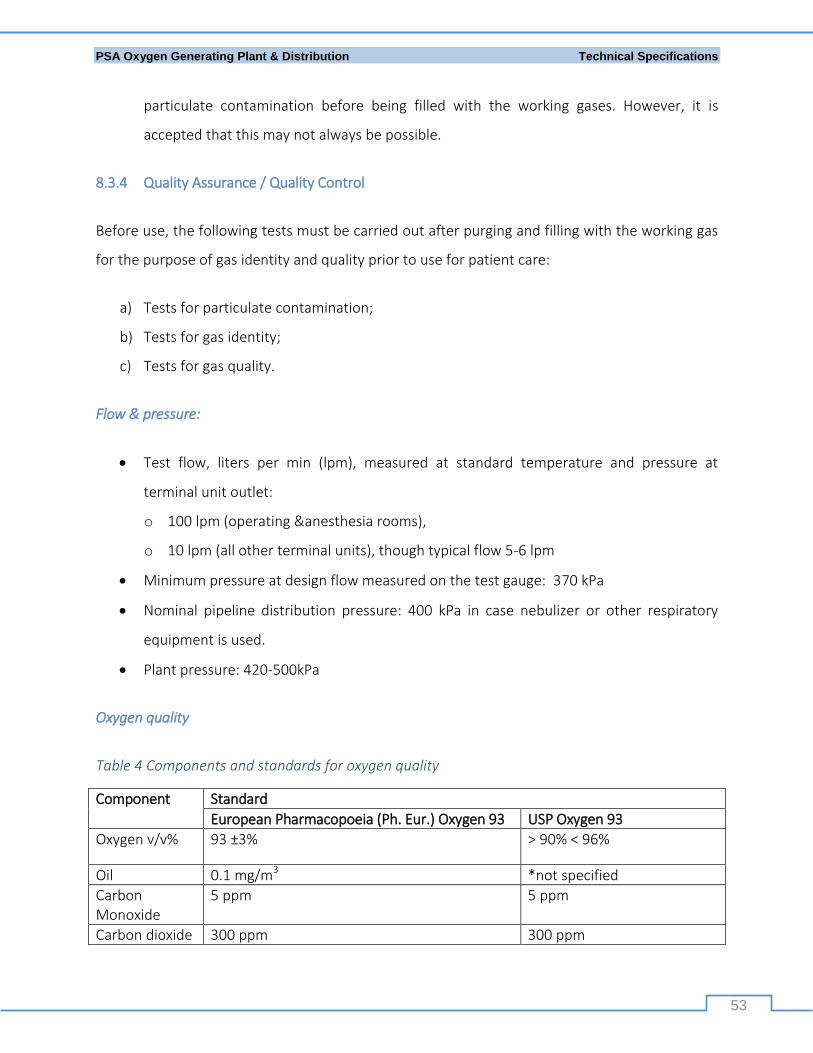
PSA Oxygen Generating Plant & Distribution Technical Specifications
53
particulate contamination before being filled with the working gases. However, it is
accepted that this may not always be possible.
8.3.4 Quality Assurance / Quality Control
Before use, the following tests must be carried out after purging and filling with the working gas
for the purpose of gas identity and quality prior to use for patient care:
a) Tests for particulate contamination;
b) Tests for gas identity;
c) Tests for gas quality.
Flow & pressure:
Test flow, liters per min (lpm), measured at standard temperature and pressure at
terminal unit outlet:
o 100 lpm (operating &anesthesia rooms),
o 10 lpm (all other terminal units), though typical flow 5-6 lpm
Minimum pressure at design flow measured on the test gauge: 370 kPa
Nominal pipeline distribution pressure: 400 kPa in case nebulizer or other respiratory
equipment is used.
Plant pressure: 420-500kPa
Oxygen quality
Table 4 Components and standards for oxygen quality
Component Standard
European Pharmacopoeia (Ph. Eur.) Oxygen 93 USP Oxygen 93
Oxygen v/v% 93 ±3% > 90% < 96%
Oil 0.1 mg/m3 *not specified
Carbon Monoxide
5 ppm 5 ppm
Carbon dioxide 300 ppm 300 ppm
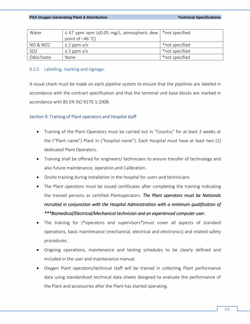
PSA Oxygen Generating Plant & Distribution Technical Specifications
54
Water ≤ 67 ppm vpm (≤0.05 mg/L, atmospheric dew point of –46 °C)
*not specified
NO & NO2 ≤ 2 ppm v/v *not specified
SO2 ≤ 1 ppm v/v *not specified
Odor/taste None *not specified
8.3.5 Labelling, marking and signage:
A visual check must be made on each pipeline system to ensure that the pipelines are labeled in
accordance with the contract specification and that the terminal unit base blocks are marked in
accordance with BS EN ISO 9170-1:2008.
Section 9: Training of Plant operators and Hospital staff
Training of the Plant Operators must be carried out in “Country” for at least 2 weeks at
the (“Plant name”) Plant in (“hospital name”). Each Hospital must have at least two (2)
dedicated Plant Operators.
Training shall be offered for engineers/ technicians to ensure transfer of technology and
also future maintenance, operation,and Calibration.
Onsite training during installation in the hospital for users and technicians
The Plant operators must be issued certificates after completing the training indicating
the trained persons as certified Plantoperators. The Plant operators must be Nationals
recruited in conjunction with the Hospital Administration with a minimum qualification of
***Biomedical/Electrical/Mechanical technician and an experienced computer user.
The training for (*operators and supervisors*)must cover all aspects of standard
operations, basic maintenance (mechanical, electrical and electronics) and related safety
procedures.
Ongoing operations, maintenance and testing schedules to be clearly defined and
included in the user and maintenance manual.
Oxygen Plant operators/technical staff will be trained in collecting Plant performance
data using standardized technical data sheets designed to evaluate the performance of
the Plant and accessories after the Plant has started operating.
PSA Oxygen Generating Plant & Distribution Technical Specifications
55
The Supplier’s technical staff will be available to provide required operational support for
at least 2 years and thereafter scheduled service/maintenance, as per agreement.
Section 10: Documentation required
The supplier of the Plantmust furnish four (4) complete sets of the following documents in
English:
1. General layout plan (schematics) for thecompletePlant, including cylinder filling ramp and
distribution manifold, with dimensional details and floor space requirements.
2. As built detailed Civil and Electro-Mechanical Engineering drawings with foundation details,
loading details,and dimensional details.
3. All documentation from the FAT and post-installation testing.
4. User and maintenance manuals, including all details and schedules of necessary works.
Section 11: Guarantees/Warranty
The Manufacturermust provide Guarantee for all equipment and Plant with respect to design,
material, construction, performance, and operation, including a guarantee against any
manufacturing defects for a period of not less than 24 months from thedate of commissioning &
handing over. Included in the costing, the manufacturer must provide all after-sales service and
free replacement of defective parts during the guarantee period. An additional extended
warranty of 8 years must be provided by the Supplier as part of a comprehensive 10-year
service/maintenance contract that will be signed with the supply and installation contract.
Section 12: Maintenance
A comprehensive maintenance/service agreement for the Plant and auxiliary equipment for a
period of ten (10) years after commissioning and handover should be considered to include the
following:
PSA Oxygen Generating Plant & Distribution Technical Specifications
56
Maintenance will consist of inspection, corrective and preventive maintenance at regular
intervals indicated by themanufacturer and outlined in the user and maintenance manual.
All equipment and accessories of the oxygen Plant will be regularly inspected, serviced and
repaired by the supplier, including replacement of parts.
An annualized operation and maintenance cost estimate for ten (10) years will be provided.
A costed list of fast moving spare parts projected for consumption for ten (10) yearswill be
provided.
The Supplier’s Engineers will undertake at least two inspection visits to the Plant during the
first year after commissioning and at least one visit per year thereafter at no additional cost
to the client.
A complete toolbox containing a set of tools, calibration and testing equipment must be
supplied with each Plant.
User and maintenance manuals will be supplied with each Plant.
The Supplier and Client must conclude an operation, service and management agreement for
10 years renewable.
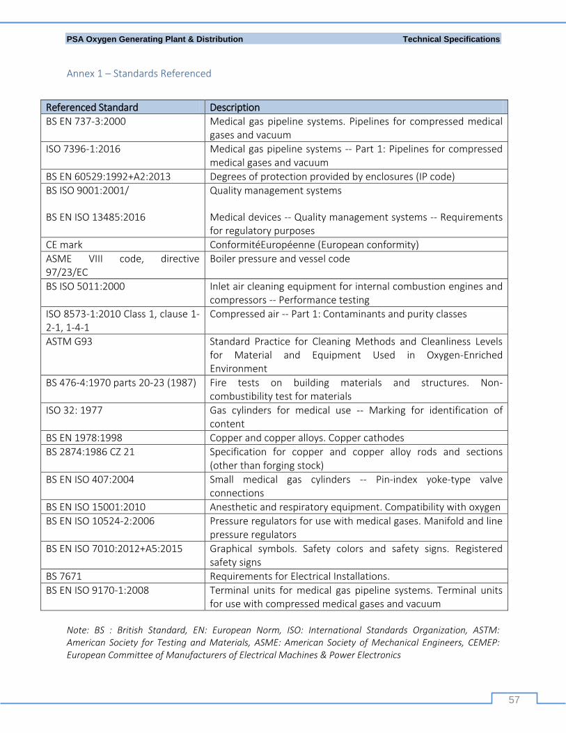
PSA Oxygen Generating Plant & Distribution Technical Specifications
57
Annex 1 – Standards Referenced
Referenced Standard Description
BS EN 737-3:2000 Medical gas pipeline systems. Pipelines for compressed medical gases and vacuum
ISO 7396-1:2016 Medical gas pipeline systems -- Part 1: Pipelines for compressed medical gases and vacuum
BS EN 60529:1992+A2:2013 Degrees of protection provided by enclosures (IP code) BS ISO 9001:2001/
BS EN ISO 13485:2016
Quality management systems
Medical devices -- Quality management systems -- Requirements for regulatory purposes
CE mark ConformitéEuropéenne (European conformity)
ASME VIII code, directive 97/23/EC
Boiler pressure and vessel code
BS ISO 5011:2000 Inlet air cleaning equipment for internal combustion engines and compressors -- Performance testing
ISO 8573-1:2010 Class 1, clause 1-2-1, 1-4-1
Compressed air -- Part 1: Contaminants and purity classes
ASTM G93 Standard Practice for Cleaning Methods and Cleanliness Levels for Material and Equipment Used in Oxygen-Enriched Environment
BS 476-4:1970 parts 20-23 (1987) Fire tests on building materials and structures. Non-combustibility test for materials
ISO 32: 1977 Gas cylinders for medical use -- Marking for identification of content
BS EN 1978:1998 Copper and copper alloys. Copper cathodes
BS 2874:1986 CZ 21 Specification for copper and copper alloy rods and sections (other than forging stock)
BS EN ISO 407:2004 Small medical gas cylinders -- Pin-index yoke-type valve connections
BS EN ISO 15001:2010 Anesthetic and respiratory equipment. Compatibility with oxygen
BS EN ISO 10524-2:2006 Pressure regulators for use with medical gases. Manifold and line pressure regulators
BS EN ISO 7010:2012+A5:2015 Graphical symbols. Safety colors and safety signs. Registered safety signs
BS 7671 Requirements for Electrical Installations.
BS EN ISO 9170-1:2008 Terminal units for medical gas pipeline systems. Terminal units for use with compressed medical gases and vacuum
Note: BS : British Standard, EN: European Norm, ISO: International Standards Organization, ASTM: American Society for Testing and Materials, ASME: American Society of Mechanical Engineers, CEMEP: European Committee of Manufacturers of Electrical Machines & Power Electronics

PSA Oxygen Generating Plant & Distribution Technical Specifications
58
Further, best practice guidance was heeded by using the following references
Health Technical Memorandum 02-01: Medical Gas Pipeline Systems - Part A Design,
Installation, Validation and Verification, published by the Department of Health (UK) in
2006.
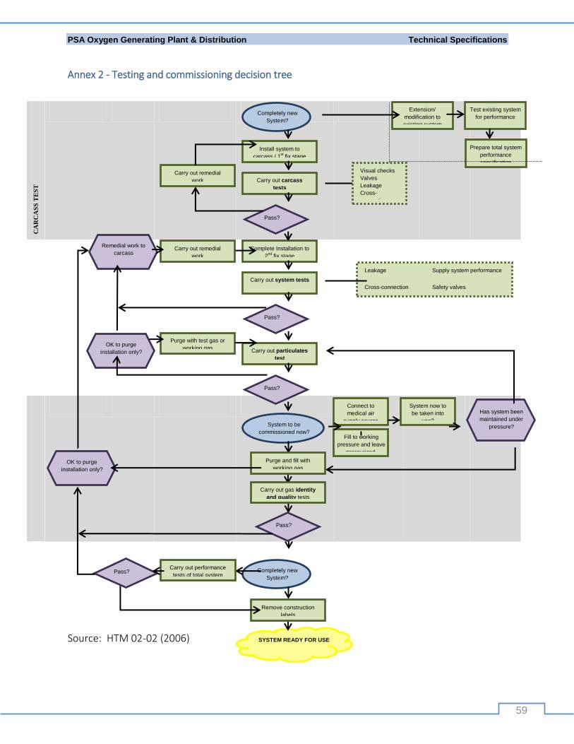
PSA Oxygen Generating Plant & Distribution Technical Specifications
59
Annex 2 - Testing and commissioning decision tree
CA
RC
AS
S T
ES
T
PIP
EL
INE
SY
ST
EM
TE
ST
S
FIN
AL
QA
/QC
CO
MM
ISS
ION
ING
Source: HTM 02-02 (2006)
Completely new
System?
System to be
commissioned now?
Pass?
Carry out particulates
test
Pass?
Carry out system tests
Complete Installation to
2nd
fix stage
Purge with test gas or
working gas
Carry out remedial
work
Pass?
Carry out carcass
tests
Install system to
carcass / 1st fix stage
Completely new
System?
OK to purge
installation only?
OK to purge
installation only?
Remedial work to
carcass
Pass?
Has system been
maintained under
pressure?
Extension/
modification to
existing system
Test existing system
for performance
Prepare total system
performance
specification
SYSTEM READY FOR USE
Connect to
medical air
supply source
System now to
be taken into
use?
Fill to working
pressure and leave
pressurized.
Leakage Supply system performance
Cross-connection Safety valves
Alarm systems Pipeline system performance
AVSU/TU/NIST function & performance
Carry out remedial
work
Purge and fill with
working gas
Carry out gas identity
and quality tests
Pass?
Remove construction
labels
Carry out performance
tests of total system
Visual checks
Valves
Leakage
Cross-
connection


