Page 1
Medication Alarm Intuitive Dispenser - M.A.I.D Elderly Assistive System
Final Design Report EEL4924C - Electrical Engineering Design 2
19 April 2011
Team: Seniors for Seniors
Members: Steven Sengberg & Christopher Wilson
Project Abstract
The end goal of this project is to assist elderly people in remembering to take their medication.
The unit consists of several containers, or drums, that contain one type of pill or a specified dosage of a
pill. Several large buttons control a graphical LCD screen that allows the user to specify a time and a
day for an alarm. Once the alarm time is set the user then clicks the buttons located in front of the
containers to indicate which pills will drop at that alarm. In addition, the system contains several other
features to increase ease of use, safety, security, and user satisfaction. The device can play sound
notifications for certain selected menu options. The system includes an RFID so that only specific
people can open the machine to load pills. Similarly, the RFID reader will also ensure that the correct
person takes the pills. The unit also includes several sensors to confirm that the pills have been removed.
The system includes functionality for text messaging the proper contact when an alarm is missed.
Finally, the machine can also act as a music player with programmable SD card and attractive volume
reacting lights.
Page 2
University of Florida EEL 4924—Spring 2011 18-Apr-11 Electrical & Computer Engineering Page 2/27 Team: Seniors for Seniors
Table of Contents
Introduction ........................................................................................................................................... 3
Current Market Solutions ....................................................................................................................... 3 Project Features ..................................................................................................................................... 4
Technical Objectives and Description of Operation ................................................................................ 5 Concept Development and Planning ....................................................................................................... 9
Components and Technology Selection ................................................................................................ 12 Project Architecture ............................................................................................................................. 15
Software Flowcharts ............................................................................................................................ 17 Distribution of Labor ........................................................................................................................... 20
Cost Objectives .................................................................................................................................... 20 Gantt Chart .......................................................................................................................................... 22
References ........................................................................................................................................... 22 Appendix ............................................................................................................................................. 23
List of Tables
Table 1: Estimated Voltage and Current Requirements .......................................................................... 8
Table 2: Distribution of Labor .............................................................................................................. 20 Table 3: Estimated Cost of Electrical Components ............................................................................... 21
Table 4: Internal EEPROM Memory Map ............................................................................................ 23 Table 5: Chip Pinout Reference............................................................................................................ 24
List of Figures
Figure 1 : Other Market Solutions .......................................................................................................... 3 Figure 2: Final Prototype Design Pictures ............................................................................................ 11
Figure 3: Xmega128A1 ........................................................................................................................ 12
Figure 4: Graphical LCD ..................................................................................................................... 13
Figure 5: SD Card ................................................................................................................................ 13 Figure 6: LM3940IT Voltage Regulator ............................................................................................... 14
Figure 7: Block Diagram of Project Components ................................................................................. 16 Figure 8: Basic Menu Structure ............................................................................................................ 17
Figure 9: Basic Alarm Structure ........................................................................................................... 18 Figure 10: Basic Interrupt Models ........................................................................................................ 18
Figure 11: Basic Alarm Signaled Structure........................................................................................... 19 Figure 12: Basic Load Structure ........................................................................................................... 19
Figure 13: Gantt Chart ......................................................................................................................... 22 Figure 14: Schematic Diagram of PCB................................................................................................. 25
Figure 15: PCB of CPLD ..................................................................................................................... 26 Figure 16: PCB of Project Circuit Board .............................................................................................. 27
Page 3
University of Florida EEL 4924—Spring 2011 18-Apr-11 Electrical & Computer Engineering Page 3/27 Team: Seniors for Seniors
Introduction
Application Domain and Problem Description
In the modern world there are millions of Americans that take several medications daily. A 2004
Survey indicated that more than 40% of Americans take at least one prescription drug and 17% take
three or more(1). Another set of data shows that 80% of people over the age of 75 take at least one
medication and that 36% of this age group will take up to four medications daily (2). The most
significant problem preventing the treating of illness is simply remembering to take the medication. In
order for a prescription and over-the-counter drugs to be effective they must be taken in compliance with
the timing and dosage specified. It is not uncommon for elderly people to have difficulty remembering
which medicine is for which particular ailment or even to take any medication due to memory problems
and depression which contribute to forgetfulness. A person is most likely to forget their medication on
days when their schedule is hectic. There are serious consequences for forgetting to take medications.
Some problems include a delayed recovery or even more severe symptoms. More than 80% of
hospitalizations for adverse drug reactions in the elderly population are dose related (3).
Invention Proposal and Project Description
The problem presented is difficult, however, Seniors for Seniors (SFS) has presented a
comprehensive solution to medicine scheduling, the Medication Alarm Intuitive Dispenser (MAID).
MAID is a pill dispenser with several features. It is designed to be one of the most reliable and cost
effective means of adhering to strict pill timing intervals.
Current Market Solutions
There are several other products that attempt to perform a similar function to MAID.
Figure 1 : Other Market Solutions
Evaluations:
1. This product limits the user to a mere 4 alarms a day. It is very expensive, has a small screen and
difficult to use alarm system. In addition, the user must lift the device and shake to dispense.
2. This product is incredibly expensive and only allows 4 alarms a day. This product also has a small
screen and complicated setup.
3. This product is also very expensive. The product requires small plastic cups and lids. Replacement
items and accessories are all expensive.
(3) Electronic Medication
Management Assistant
$744.95
(2)Tamper proof e-pill
compuMed
$844.95
(1)Med-e-lert Automatic Pill
Dispenser
$69.95-$289.95
Page 4
University of Florida EEL 4924—Spring 2011 18-Apr-11 Electrical & Computer Engineering Page 4/27 Team: Seniors for Seniors
Project Features
Simple, Easy-to-Use and Set Up
MAID is conveniently equipped with an easy setup; a standard simple wall outlet will suffice
for power. There is no need to tinker and fiddle with difficult to insert batteries. The unit also features a
user friendly interface with reactive, light up large buttons for easy use. Furnished with a large
graphical LCD screen it is simple to read text and interact. The GLCD also includes a bright backlight
that is automatically turned on making it easy to read at any time of the day.
Variety and Flexibility
MAID is able to hold up to 7 different types of medications. Utilizing a simple interface an
individual can set up to 12 timed alarms for different days at different times and specify which pills to
dispense at that time.
Secure and Accurate
MAID is secure and accurate. An easy- to- use RFID card reader ensures that the qualified
individual will be the only one granted access to load pills into the pill compartments. In addition, the
card reader will also confirm the proper individual is there to receive the correct pills in the case that
there is more than one machine.
Informative and Customizable
The main priority of the product is to alert an individual to take their pills. The system comes
with an alarm and several preset songs to use as the warning, allowing users to customize their medical
schedule experience. As a further level of customizability users can add their own songs by placing it on
an SD card. MAID also includes a temperature sensor to inform the user of the current temperature
conditions in Fahrenheit or Celsius. This product is incredibly informative and it will even announce
the different options as the user browses the menus.
Reliable and Safe
Intelligently included in the design is a sensor to confirm that the pills were dropped from the
pill dispensing area and there are warning messages if a pill fails to drop. In addition, a GSM module
has been added to the project that allows it to text message a designated person if any of the alarms goes
off and no one retrieved the pills. The user can easily set this contact phone number from the menu. On
the event of a power outage the device retains the time, date and all alarm settings.
Entertaining and Fun
MAID can also entertain for hours with a complete light up display that responds to the volume
of music being played. The device presents this viewing experience in conjunction with clear stereo
sound. Also included for even more customizability in the project are two separate adjustable left and
right audio controls that allow the user to manipulate the sound to their own preferences. In addition, the
front pill selection buttons can be converted to play musical notes. The last incredible feature allows
users to see and play different videos for their amusement.
Page 5
University of Florida EEL 4924—Spring 2011 18-Apr-11 Electrical & Computer Engineering Page 5/27 Team: Seniors for Seniors
Technical Objectives and Description of Operation
The main object of the MAID is to ensure accurate and safe distribution of pills to users. This
section details the expected Operation and Goals of MAID. A Primary objective of our project is to
design a system that can sound an alarm at a certain time and dispense the proper medication with RFID
confirmation.
The device dispenses the proper amount by relying feedback through an optical encoder and
precision control with stepper motors.
The RFID reader will have to read a card and confirm that it is the correct person trying to receive
the medication then send a signal to allow the medication to be dispensed.
The microcontroller is connected to a real-time clock and also sends the appropriate signals to the
CPLD and peripherals.
The CPLD contains the state machine that controls the motor motion.
Main Menu Operation:
1. Upon turning on the device the user will see the logo and animation for M.A.I.D. on the
Graphical LCD.
2. The User will then see the main menu. The Main menu has several different selection options in
addition to displaying the day, date, month, time, and temperature at the top of the screen.
3. The Main menu will always display the current time in addition to a) Adjust Alarm b)Load
Medication c) Select Sound d) set time e)gsm debug f)change temp unit g) change phone # h) set
quick alarm i)play music j)play video k)play game l)set voice on off
4. The User can access the loading medication and setting time menus if they are the administrator.
5. If the User tries to swipe with the Patient Card nothing happens at the Main Menu
Set Alarm Selection
1. Once adjust alarm is selected the screen will then prompt the user for if they wish to set an alarm,
remove and alarm or return to the main menu
2. If Set alarm is chosen screen will then display All the Days of the Week and a cursor indicates
which day is currently selected and it will also display "Back" which allows the user to Return to
Previous Screen
3. Once a Day is selected the screen will then display The Day at the Top and 6 slots for different
alarms as well as "Back" to Return to the Previous Screen. There is also a "Next Page" option
that allows the user to see the other 6 alarms that can be set for that day.
4. After setting the time the user is prompted to select which pills should be dispensed at that time
by clicking on the 7 drum buttons.
5. Once one of the alarms is selected the user will then use the arrow keys to select the proper time
for their alarm, and the previous screen will be updated to show that there is an alarm set.
Page 6
University of Florida EEL 4924—Spring 2011 18-Apr-11 Electrical & Computer Engineering Page 6/27 Team: Seniors for Seniors
Remove Alarm Selection
1. Once adjust alarm is selected the screen will then prompt the user for if they wish to set an alarm,
remove and alarm or return to the main menu
2. If remove alarm is chosen screen will then display All the Days of the Week and a cursor
indicates which day is currently selected and it will also display "Back" which allows the user to
Return to Previous Screen
3. Once a Day is selected the screen will then display The Day at the Top and 6 slots for different
alarms as well as "Back" to Return to the Previous Screen. There is also a "Next Page" option
that allows the user to see the other 6 alarms that can be set for that day.
4. The user can then select any of the 12 alarms and just click on it to remove the alarm.
Load Medication Selection
1. When Set Alarm is selected the Screen will display "Swipe the Administrator Card to Proceed" It
will also have a "Go back" option if the user selected the option accidently.
2. MAID will then wait until it detects that the Administrator card was swiped.
3. When the administrator card is swiped the words "The Pill Area is now Unlocked" appears. The
servo unlocks the pill section. If the pill section is not opened within 8 seconds the servo relocks
and sends the user back to the main menu.
4. After a few seconds will then display "Select a Pill Type to Load" it will also display all the pill
types and a back selection.
5. The user can then use the arrow keys to select the type of pill. Each time the user clicks the
wheel will rotate one slot.
6. When the user is finished back can be selected or the user is automatically returned to the main
menu when the door is closed. Once the door is closed the servo automatically locks it.
Sound Selection
1. This screen can be accessed by anyone. It allows the user to choose which song to play as an
alarm.
2. The screen will display the "Change Alarm Music." Also displayed are the current song number
and the file name. The user can use the arrow keys to change the song and then click play to hear
the alarm.
Set Time Selection
1. When this option is selected the user will then be prompted for the administrator card. If the
wrong card is swiped the screen will display which card is being swiped.
2. Once the proper card is swiped the user is taking to a screen where they can use the arrow keys
to adjust the Month, Day, Date and the time.
3. There is a selection for back and accept.
Page 7
University of Florida EEL 4924—Spring 2011 18-Apr-11 Electrical & Computer Engineering Page 7/27 Team: Seniors for Seniors
GSM Debug Selection
1. This selection is not intended to be part of the final prototype but is more a reference for using
the GSM.
2. The Options for this menu are 1) start GSM 2) send SMS 3) Listen GSM and 4)Send AT
3. When initializing the GSM this screen can be used to see if it has been registered to the network.
4. Send SMS allows the user to send a message and the temperature to the contact phone number
3. There are also "back" and "accept" buttons, if back is selected the user returns to the menu, if
accept is selected the selection is saved as the alarm.
Change Temperature Unit Selection
1. Clicking this option will immediately change the temperature on the Main Menu to the other
unit. Only does Fahrenheit and Celsius.
Change Phone Number
1. This Option takes the user to a screen that displays the currently set phone number at the top.
2. The user can use the directional arrow keys to change the number and can select back or accept.
3. The number is saved to EEPROM and like the alarms is not lost in a power out.
Set Quick Alarm
1. This setting is mainly for demonstration and testing purposes. It will automatically set an alarm
for 5 seconds after the current time.
2. The alarm is also set so that each of the medication types should be dispensed.
Play Music Selection
1. This screen is similar to select sound but it has several options including "play all" "pause" "fast
forward" "reverse" and back.
2. This option allows the player to act more as a media player.
3. In addition, in this option mode the music will not stop even upon returning to the main menu.
Play Video Selection
1. In this option the user can use the arrow keys to select the movie to play.
2. Once selected the movie will play with sound and can be stopped with any button press.
Play Game Selection
1. The play game section turns the 7 pill selection button into notes on a scale. The up and down
directional keys can shift the scale.
Set Voice On or Off Selection
1. This selection will turn on narration for the options in the main menu.
2. Once selected the voice will tell the user that narration has been turned on. When the user
browses through the main menu the voice will announce each selection as well as saying
"selected" when a particular option is chosen.
Page 8
University of Florida EEL 4924—Spring 2011 18-Apr-11 Electrical & Computer Engineering Page 8/27 Team: Seniors for Seniors
Medication Alarm and Pill Dispensing
1. When the Time for an alarm is activated the screen will switch to an alarm menu where it
prompts the user for the patient card.
2. As the alarm menu is displayed the selected alarm music will also begin playing.
3. If no one comes to retrieve the pills, after a certain time the alarm will send a text message to the
designated number and switch to a screen to notify the user an alarm was missed.
4. If the patient is there and then swipes their card and the following will occur:
a. The motors for the specific pill type will rotate and drop the pills into a bottom container.
b. The IR sensor will detect that every pill that was selected dropped.
c. If a specific pill type does not drop there will be a warning prompt after the rest of the
pills have been dispensed.
5. The user will then be taken back to the main menu.
Power Consumption
Components Voltage Current (max)
Xmega128A1 3.3V 30mA
GLCD ST7565 3.3V 400uA
CPLD 5V 300mA
Realtime Clock DS1307 5V 1.5mA (Battery)
LM386N-4 5V 300mA
Quadruple Half-H Driver
SN754410
5V 1.3A
RFID 5V 120mA
LEDS 3V 200mA
GSM Module 5V 2A
Max Current 4.25A
Table 1: Estimated Voltage and Current Requirements
Page 9
University of Florida EEL 4924—Spring 2011 18-Apr-11 Electrical & Computer Engineering Page 9/27 Team: Seniors for Seniors
Concept Development and Planning
The mechanical design and the project description have changed several times after the initial
presentation of the design. Below are some of the design decisions and models planned before the
current version.
1. The first version although independently developed resembled several of the current market
solutions. It used several of the medicine boxes similar to the MTWTFSS boxes offered in
pharmacies. The main dropping mechanisms at this point were several solenoids at each of the
box locations.
a. Main processor was to be a larger sized MSP430 - Problem with this was the amount of
shipping time and so this was eventually changed.
b. Main methods of dropping pills were solenoids. At the time of research, however, there
were none on the market that met the power and cost constraints of the project
c. There was no second pair of IR detection to determine if pills were dropped
d. RFID was not present in this design or the RTC.
e. The pill boxes were utilized instead of the Rotating wheel
2. The second major version was developed after conversations with Dr. Schwartz and in class
suggestions to the project.
a. This design had the main microprocessor as the Atmega, and then it would communicate
with several smaller MSP430s
b. The Main method of dropping pills was changed to motors to better support the new
circular dispenser design
c. Second pair of IR detection added along with another button to drop pills
d. RFID was added to this design for complexity. It would also function as the component
to control who would load the pills and set the alarms
e. Rotating wheel design now implemented
3. The version for the initial class presentation
a. This design has the main microprocessor as the Atmega specifically for a greater number
of I/O pins
b. This design added an additional Atmega to control EEPROMS for sound selection
c. The MSP430s were replaced with a CPLD for a greater pin count
d. Graphical LCD added instead of smaller LCD to show more on the menus
e. RTC added to keep track of day.
Page 10
University of Florida EEL 4924—Spring 2011 18-Apr-11 Electrical & Computer Engineering Page 10/27 Team: Seniors for Seniors
4. Completed Prototype Version (Demonstration Day)
a. This design has the main microprocessor as the Xmega128A1 as the sole microprocessor.
This particular chip had a breakout board available that was easy to use for testing as well
as 78 I/O pins.
b. SD Card was added for sound selection instead of the EEPROMs. The Internal EEPROM
would be used to keep track of Alarms and other user customized selections.
c. CPLD implementation was changed to allow all the motors to run off of it.
d. GLCD as well as the backlight to it was added.
e. DS1307 and battery were used to maintain time instead of internal RTC.
f. RFID and GSM added for features.
g. Servo added for a locking mechanism.
h. Stepper Motors replaced the original motor purchase. These were connected to the
dispensing drums with rubber bands.
i. Temperature Sensor added
j. Housings and enclosures for all components built out of wood.
k. Also included custom switches and potentiometers with dials
Final Prototype as seen on Demonstration Day:
Page 11
University of Florida EEL 4924—Spring 2011 18-Apr-11 Electrical & Computer Engineering Page 11/27 Team: Seniors for Seniors
Figure 2: Final Prototype Design Pictures
Page 12
University of Florida EEL 4924—Spring 2011 18-Apr-11 Electrical & Computer Engineering Page 12/27 Team: Seniors for Seniors
Components and Technology Selection
Digital Components
1. Atmel AVR Microprocessor (Atmega 128A1) - The Atmega128A1 was chosen over the original
Atmega324P, PIC and the MSP430 of junior design, mainly due to its number of Input / Output
pins (78 available). In addition, a breakout board was purchased from sparkfun to allow easy and
immediate debug and testing. The chip also has a much larger memory which was needed for the
incredible amount of code utilized. The chip can support up to 4 SPI, TWI, and UART devices.
It is low power and faster than the other. See device manual for other details.
Figure 3: Xmega128A1
2. CPLD (MAX7000s-EPM7064SLC44-10) - The CPLD is necessary once again due to the large
number of Input / Output pins. This particular unit has 40 pins that can be used. In addition, the
functions of the Pins and the controls can be easily reconfigured for any purpose.
3. RFID Reader - This component is necessary because the MAID needs a secure means of
determining identification. It is critical to have someone who is knowledgeable about the
medications and dosage to be the only one able to load and set alarms.
4. Real Time Clock (RTC - DS1307) - This component is significant for several reasons. The first
is it needs to be powered with an additional 3.3v battery. This allows the unit to keep track of the
date and the time even if the power is removed. The RTC is also easily communicates with the
microprocessor through I2C communication.
5. Graphical LCD Screen (TG12864H3-04A) - The graphical LCD was chosen over the standard
LCD because the Graphical LCD has more room on the screen to display information. This is
critical because the user interface needs to be simple and easy to set up, a larger menu is one
method of accomplishing this goal. In addition the Graphical LCD also allows pictures which
will be used for a logo and instructions. The Graphical LCD can also be used for video.
Page 13
University of Florida EEL 4924—Spring 2011 18-Apr-11 Electrical & Computer Engineering Page 13/27 Team: Seniors for Seniors
Figure 4: GLCD
6. Internal Chip EEPROM - It should be noted that the internal EEPROM is only 2k but it is large
enough to store the alarms and several user customized choices.
7. SD Card - The SD Card is necessary because the sounds that are used take a substantial amount
of space. The Atmega processor does not retain enough internal memory to save the sound
therefore external memory is needed. In addition, this memory must be non-volatile so the sound
files are not lost. Finally, the SD card is convenient to use because most computers have a port
that will support the card.
Figure 5: SD Card
8. Temperature Sensor - This component is used to allow the user to see the current ambient room
temperature. This is different from the built in chip temperature sensor which only detects the
chip temperature.
9. GSM Module - This component was necessary to send text messages to the designated number
as warnings if pills were not taken. The module used has an easy to use housing to slip the SIM
card in.
Page 14
University of Florida EEL 4924—Spring 2011 18-Apr-11 Electrical & Computer Engineering Page 14/27 Team: Seniors for Seniors
Analog Components
1. ADC Components
a. Infrared Sensors / Photodiodes Sensors - The Infrared and Photodiodes are used together
for detection. The first pair is necessary to detect if pills are actually dropped when the
alarm goes off. The main concern is the machine has no simple means of detecting how
many pills are left in the dispenser. The other pairs are used in conjunction with the
motor encoders for position.
b. Volume Control Potentiometers - This component is mainly so that the user can adjust
the volume level of the alarms. Turning the control all the way in one direction will turn
off the sound, the added flashing lights are critical as an alarm indicator.
c. ADC Pins are built into the Atmega and this allows us to read in Analog Values
specifically for the photodiode receivers.
2. DAC Components
a. Speakers - The speakers are needed to play sound for the alarm.
b. Amplifiers (LM386N) - The op amps are necessary to boost the sound to increase the
volume of the alarm.
c. DAC (LTC1661) - This is a serial DAC to allow us to save us on use of pins.
Mechanical Components
1. Stepper motors - The motors are the key component in driving the Pill Dropping mechanism.
The pill dropping system work so that the pills are loaded into a large wheel. This wheel is then
turned by the motor to dispense the pills. The wheels/drums that are turned by the stepper motors
have encoding placed on them for position.
2. Servo - The servo is an easy component to use to control the locking mechanism for the pill
dispensing area. It can have several set positions that are easy to program for a simple lock
unlock state.
Miscellaneous Components
1. LEDs - LED's are necessary in several locations in the design. The most important is the LEDs
light up when the pill selection button is pressed. This lets the user know which pills are selected
to drop at a specific alarm.
2. Push Buttons - The Push Buttons are used for two primary reasons. The first reason is that
several push buttons are used to control the menu options on the LCD screen. The second reason
is they are used to select which pills are to drop at a specific alarm.
3. Resistors
4. Capacitors
5. Voltage Regulator (LM3940IT) - Several Components require a 3.3v power supply instead of the
5v supply provided by the wall plug.
Figure 6: LM3940IT Voltage Regulator
6. Hardstock Wood - This material is cheap and study. It will be the primary construction material
for the casing of the MAID.
7. Screws, Brackets
8. 3.3V Battery - Necessary for the RTC.
Page 15
University of Florida EEL 4924—Spring 2011 18-Apr-11 Electrical & Computer Engineering Page 15/27 Team: Seniors for Seniors
Project Architecture
This section is a broad description of how the different components in the project interface together.
Xmega128A
The Xmega is the chosen microprocessor for this project and is the central component that reacts
almost directly with every other component in the project.
RTC (DS1307)
The RTC reacts with the microprocessor through an I2C communication channel
It serves to retain the current month, day, date and time settings
SD Card
The SD card communicates with the microprocessor through SPI communication
It holds the sound tracks that can be played for the alarm
Retains Miscellaneous Information:
o Voice Narration
o Introduction Animation and Logos
o Video / Audio files for video playback
RFID
The RFID communicates with the microprocessor through the USART
The RFID serves primarily to identify which card is placed in front of it, there were several
features that could have been used but there was not enough time to implement them.
GLCD
Communicates to the microprocessor through bit banging
Relies on information stored on the SD card for images and video.
DAC / Speakers / Amplifiers
Serial Connection to the Microprocessor to play sound
IR / Photoresistors
Relies on the built in ADC on the Microprocessor to determine values
Temperature Sensor
The sensors uses Dallas 1-wire communication to transmit the temperature
GSM
USART communication with the microprocessor. Allows the user to send text messages.
CPLD
Receives an encoded signal from the microprocessor to specify which motors to turn.
Functions as a state machine to send signals to the motor drivers.
Stepper Motors
The phases are powered by the motor drivers.
Page 16
University of Florida EEL 4924—Spring 2011 18-Apr-11 Electrical & Computer Engineering Page 16/27 Team: Seniors for Seniors
Figure 7: Block Diagram of Project Components
Page 17
University of Florida EEL 4924—Spring 2011 18-Apr-11 Electrical & Computer Engineering Page 17/27 Team: Seniors for Seniors
Software Flowcharts
There was a substantial amount of programming that was involved in this project. The following
diagrams are only a very general description of the process that occurs, and it does not even cover all the
options and situations that are involved in the actual project. A significant time constraint prevents us
from discussing all the possible options. In addition, these are not detailed flowcharts that discuss the
variables manipulated; most of the boxes represent entire function calls.
Figure 8: Basic Menu Structure
Page 18
University of Florida EEL 4924—Spring 2011 18-Apr-11 Electrical & Computer Engineering Page 18/27 Team: Seniors for Seniors
Figure 9: Basic Alarm Structure
Figure 10: Basic Interrupt Models
Page 19
University of Florida EEL 4924—Spring 2011 18-Apr-11 Electrical & Computer Engineering Page 19/27 Team: Seniors for Seniors
Figure 11: Basic Alarm Signaled Structure
Figure 12: Basic Load Structure
Page 20
University of Florida EEL 4924—Spring 2011 18-Apr-11 Electrical & Computer Engineering Page 20/27 Team: Seniors for Seniors
Distribution of Labor
The following is chart is segmented into the different sections and the project labor for each team
member.
Divisions Steven Sengberg Christopher Wilson
Preliminary Research 35 65
Design Phase Mechanical Design 65 35
Software Design 40 60
Board Construction Bread Board 50 50
PCB 60 40
Test and Debug HW / SW 50 50
Physical Assembly 50 50
Table 2: Distribution of Labor
Cost Objectives
Component Part # Quantity Price Per item Amount
Rotary Stepper motor PF55-48D1 7 $ 2.00 $ 14.00
RFID Module YHY502CTG 1 $ 29.99 $ 29.99
RFID Cards MF1 IC S50 2 $ 3.59 $ 7.18
PTC Fuses PTCCL13H921DBE 7 $ 0.68 $ 4.79
IC Half-H Driver SN754410 7 $ 2.33 $ 16.31
IR Emitter 940nm WP7104F3C 8 $ 0.20 $ 1.60
Phototransistor 940nm LTR-4206E 8 $ 0.30 $ 2.40
5k Ohm Trimpot 3319P-502-ND 2 $ 0.36 $ 0.72
Actuator Magnet HE153-ND 5 $ 0.99 $ 4.95
Reed Switch HE556-ND 1 $ 0.44 $ 0.44
Blue Cylinder LED 365-1201-ND 4 $ 0.34 $ 1.36
Blue Round LED 365-1180-ND 10 $ 0.34 $ 3.40
2GD SD Card N82E16820134029 1 $ 6.99 $ 6.99
Alliance Big Bands 70350069 1 $ 0.83 $ 0.83
Graphic ST7565 LCD
128x64 ST7565 1 $ 19.41 $ 19.41
SD Breakout board BOB-00204 1 $ 9.95 $ 9.95
Xmega100 Breakout BOB-09546 1 $ 24.95 $ 24.95
DS18B20 Temperature
Sensor SEN-00245 1 $ 4.25 $ 4.25
Cellular Antenna CEL-00290 1 $ 11.95 $ 11.95
Stackable Header PRT-10007 4 $ 1.50 $ 6.00
GSM/GPRS SM5100B CEL-09533 1 $ 59.95 $ 59.95
SM5100B Evaluation Board CEL-09427 1 $ 59.95 $ 59.95
Page 21
University of Florida EEL 4924—Spring 2011 18-Apr-11 Electrical & Computer Engineering Page 21/27 Team: Seniors for Seniors
3 wire servo 276-2162 1 $ 19.95 $ 19.95
Acrylic Sheet 32"x44"
1 $ 23.98 $ 23.98
2" strap Hinge
1 $ 2.48 $ 2.48
Narrow Hinge
1 $ 1.96 $ 1.96
CAT 3 Riser (ft)
130 $ 0.03 $ 3.90
Masking tape
1 $ 2.48 $ 2.48
Furring Strip
6 $ 0.98 $ 5.88
Dark oak painted Nails
1 $ 1.73 $ 1.73
Corner Molding
2 $ 2.55 $ 5.09
2x4 Oak
2 $ 8.27 $ 16.54
Wood Glue
1 $ 3.54 $ 3.54
3/4" Nails
1 $ 1.24 $ 1.24
1/8"-4" Screw
2 $ 2.58 $ 5.16
3"x2' PVC
1 $ 4.95 $ 4.95
4x1/2 Philips screw
1 $ 1.18 $ 1.18
4-40x1/2 Round screw
1 $ 1.18 $ 1.18
10X3/4 Round steel wood
screws
2 $ 1.18 $ 2.36
1/4 Sheet clamp on screw
1 $ 1.68 $ 1.68
8x3/4 Philips wood Screws
1 $ 4.97 $ 4.97
Corner Brackets
4 $ 1.77 $ 7.08
8x11/4 Philips wood screw
1 $ 5.58 $ 5.58
Kynar Wire wrap
3 $ 3.99 $ 11.97
Total $ 426.24
Table 3: Estimated Cost of Electrical Components
Page 22
University of Florida EEL 4924—Spring 2011 18-Apr-11 Electrical & Computer Engineering Page 22/27 Team: Seniors for Seniors
Gantt Chart
Figure 13: Gantt Chart
References
(1) http://www.mapinc.org/drugnews/v04/n1730/a06.html
(2) http://www.netdoctor.co.uk/health_advice/facts/medicationelderly.htm
(3) http://www.livestrong.com/article/206756-about-the-elderly-forgetting-to-take-medications/
Page 23
University of Florida EEL 4924—Spring 2011 18-Apr-11 Electrical & Computer Engineering Page 23/27 Team: Seniors for Seniors
Appendix
EEPROM Memory Map [hr][min][sec][am/pm][pills]
Page # Contents Details:
0 Monday Alarms 6 Alarms 5 Locations Each 0-29 used 30-31 free
1 Tuesday Alarms 6 Alarms 5 Locations Each 0-29 used 30-31 free
2 Wednesday Alarms 6 Alarms 5 Locations Each 0-29 used 30-31 free
3 Thurday Alarms 6 Alarms 5 Locations Each 0-29 used 30-31 free
4 Friday Alarms 6 Alarms 5 Locations Each 0-29 used 30-31 free
5 Saturday Alarms 6 Alarms 5 Locations Each 0-29 used 30-31 free
6 Sunday Alarms 6 Alarms 5 Locations Each 0-29 used 30-31 free
7 Monday Next Alarms 6 Alarms 5 Locations Each 0-29 used 30-31 free
8 Tuesday Next Alarms 6 Alarms 5 Locations Each 0-29 used 30-31 free
9 Wednesday Next Alarms 6 Alarms 5 Locations Each 0-29 used 30-31 free
10 Thurday Next Alarms 6 Alarms 5 Locations Each 0-29 used 30-31 free
11 Friday Next Alarms 6 Alarms 5 Locations Each 0-29 used 30-31 free
12 Saturday Next Alarms 6 Alarms 5 Locations Each 0-29 used 30-31 free
13 Sunday Next Alarms 6 Alarms 5 Locations Each 0-29 used 30-31 free
14 Temperature Setting 1 setting 1 location 0 used
15 Phone Number Setting
3 Phone
#s 10 Locations Each xxx-xxx-xxxx 30-31 free
16
17
18
19
20 Voice Recognition 1 setting 1 location 0 used
Table 4: Internal EEPROM Memory Map
Page 24
University of Florida EEL 4924—Spring 2011 18-Apr-11 Electrical & Computer Engineering Page 24/27 Team: Seniors for Seniors
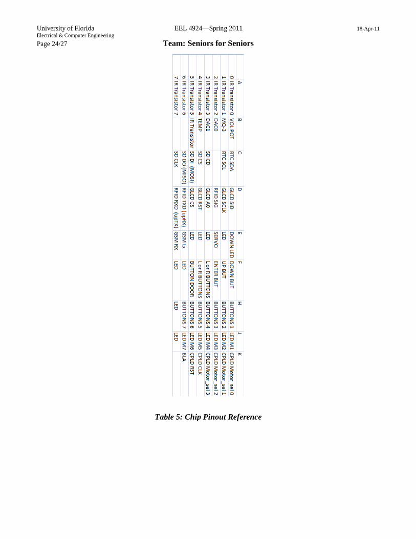
Table 5: Chip Pinout Reference
Page 25
University of Florida EEL 4924—Spring 2011 18-Apr-11 Electrical & Computer Engineering Page 25/27 Team: Seniors for Seniors
Figure 14: Schematic Diagram of PCB
Page 26
University of Florida EEL 4924—Spring 2011 18-Apr-11 Electrical & Computer Engineering Page 26/27 Team: Seniors for Seniors
Figure 15: PCB of CPLD
Page 27
University of Florida EEL 4924—Spring 2011 18-Apr-11 Electrical & Computer Engineering Page 27/27 Team: Seniors for Seniors
Figure 16: PCB of Project Circuit Board