27
Medication Dispensing Device RERC ACCESSIBLE MEDICAL DEVICE OPTIMAL DESIGN

Medication Dispensing DeviceRERC ACCESSIBLE MEDICAL DEVICEOPTIMAL DESIGN
Team 6 Kevin Villani, Eva-Marie Suarez, Jacquelyn MasseNovember 11, 2005

Outline
I. Introduction
II. Design
1. Basic Components and Locations2. Vacuum Fan Requirements3. Robotic Arm
i. Servo Operating Theory and Circuitsii. Vacuum retrieval assembly
4. Pill Capture and Cutter 5. Storage assembly6. PDA and LabVIEW7. Barcode Scanner8. Dispensing Assembly9. Pathway of the Pill
III. Budget
IV. Appendix1. USB 6008/6009 Device Block Diagram
INTRODUCTION
With individuals taking a growing number of different drugs, the market
has developed several ways of making medications easier to handle. Products
range from simple containers to store pill dosages per day, hand held pill cutting
tools, and medication reminder alarms to more expensive, complex devices.
Many of these devices can be problematic for people with poor eyesight, limited
fine motor skills or mobility, Parkinson’s Disease, or other physical ailments. The
lack of existing products on the market to suit such clientele gives rise to the
need for an automated medical device that will administer medication to the
patient in an accurate, dependable manner.
The device will be cost-efficient and reliable. It must remain accessible
and easy to use for individuals who lack fine motor control, are vision impaired,
or are limited by unsupported vertical access. The size and portability should be
suitable for residential or clinical settings. Automation will be the device’s most
distinguishing feature. It will mechanically regulate medication of 1, ½, or ¼ pills
of various sizes and shapes and will manage many different medications at once.
Ideally, the device will have alarms to signify the time medication needs to be
taken or refilled. Information regarding dosage amounts, times, and expiration
dates will be internally stored and a tracking system will record a history of
dosages dispensed.

DESIGN
Basic Components and Locations
Components are located within the case, located to allow for ease of access and ease of replacement. Above is a component breakdown of major assemblies within the device.
Figure 1

Vacuum Fan Requirements
Based on the maximum pill weight and the minimum pill thickness a vacuum requirement is identified. This requirement provides the differential pressure across the medication to ensure the medication can be removed from the storage module and delivered to the rejection assembly. By using simple pressure and weight definitions a relationship for the required differential pressure is attained. By measuring several over-the counter and prescription medications a minimum thickness was found to be 4 mm, while the maximum mass was approximately 1000mg. Substituting these values into the equation below a net pressure difference required was found to be 6.4kPa. In more traditional units of vacuum this corresponds to 1.94 in Hg. Keeping in mind that traditional vacuum systems draw a vacuum of 27 to 29 in Hg. Centrifugal fans systems are evaluated in meters of water, the range of operating head is 0.5 to 1.5 meters of water. The corresponding required differential pressure is 0.0622 meters of water, well within expected operating head.
To satisfy this requirement we have selected a fan impeller from a dirt devil 6000 series battery vacuum. The vacuum sells on-line for approximately $55 however, the impeller is also available for sell for $4.95.
Using a centrifugal fan impeller has several advantages over other vacuum generating options. First the price centrifugal fans are lower. Secondly, a centrifugal fan reaches shut off head. This shutoff head prevents drawing too high of a vacuum while still maintaining the fan in operation. This means that for our application there is a requirement that a pill be held by the vacuum tube and moved. By reaching shutoff head the pump will continue to spill however moving no air unless air slips into the system either from leakage by the pill or across the pump. Third this pump weighs less and is far easier to construct than other vacuum assemblies.
The vacuum fan assembly will be driven by 120 VAC power source Fan and system characteristic curves are used to determine the flow rates and pressures within closed systems. By measuring the differential pressure across the fan at various speeds and volumetric flow rates, a graphical representation of the fan operating characteristics can be achieved. Coupling this operating characteristic curve and a system operating curve; specific system flow rates and operating pressures can be determined by the points of intersection between the various curves, commonly referred to as “fan laws”.
Figure 2
P = F/AF =mgA= πr2
Therefore,P= mg/ πr2
(Equations)

Robotic Arm
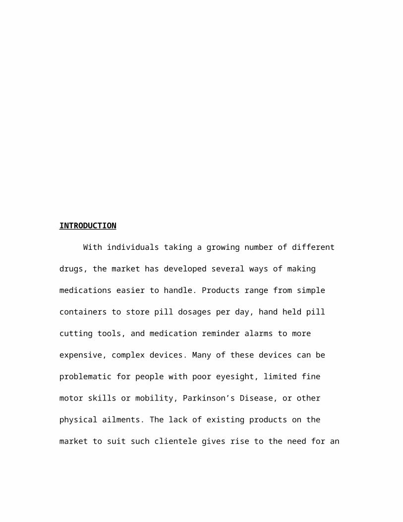
The major transport method employed by this device is the use of a robotic arm. The robotic arm was chosen not only for the “bells and whistle” quality it possesses but also because it has a wide margin of versatility, one to one control over medication through process, allows for verification of medication at point of retrieval. The Robotic arm is used to move medication from storage to the cutting assembly and from storage to dispensing. Several additional actions are required from the arm as part of cutting sequences and loading sequences. The Robotic arm will be constructed of high density polyethylene due to its strength and chemical resistance. This arm has two axis of motion. The first is a horizontal swing arm with a range of 180 degrees limited to 95.5 degrees for this application. The orientation of the swing arm allows for the placement of the vacuum assembly above any assembly located along the swing arm arc. Control of the swing arm is via a servo motor and the PDA running LabVIEW through a data acquisition box(DAQ). This servo motor requires a command wire besides a ground and positive 6V power supply. The command wire requires the use of one analog channel from the DAQ box. Operating the servo motor requires the following knowledge.

Figure 3. Servo motor(Parallax)
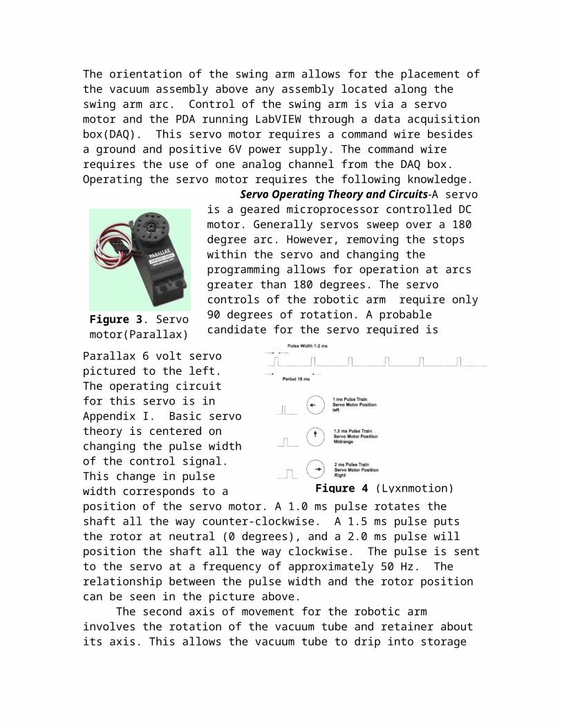
Servo Operating Theory and Circuits-A servo is a geared microprocessor controlled DC motor. Generally servos sweep over a 180 degree arc. However, removing the stops within the servo and changing the programming allows for operation at arcs greater than 180 degrees. The servo controls of the robotic arm require only 90 degrees of rotation. A probable candidate for the servo required is Parallax 6 volt servo pictured to the left. The operating circuit for this servo is in Appendix I. Basic servo theory is centered on changing the pulse width of the control signal. This change in pulse width corresponds to a position
of the servo motor. A 1.0 ms pulse rotates the shaft all the way counter-clockwise. A 1.5 ms pulse puts the rotor at neutral (0 degrees), and a 2.0 ms pulse will position the shaft all the way clockwise. The pulse is sent to the servo at a frequency of approximately 50 Hz. The relationship between the pulse width and the rotor position can be seen in the picture above.
Figure 4 (Lyxnmotion)
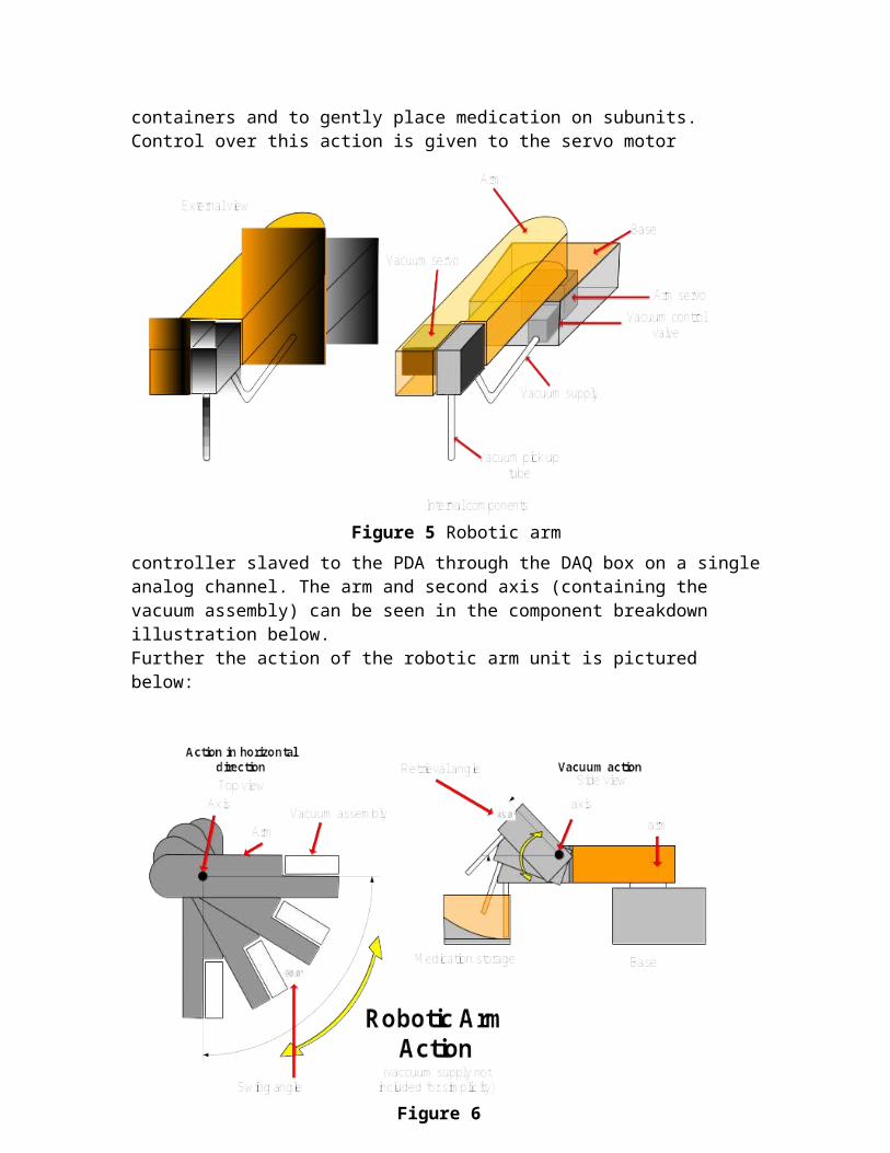
The second axis of movement for the robotic arm involves the rotation of the vacuum tube and retainer about its axis. This allows the vacuum tube to drip into storage containers and to gently place medication on subunits. Control over
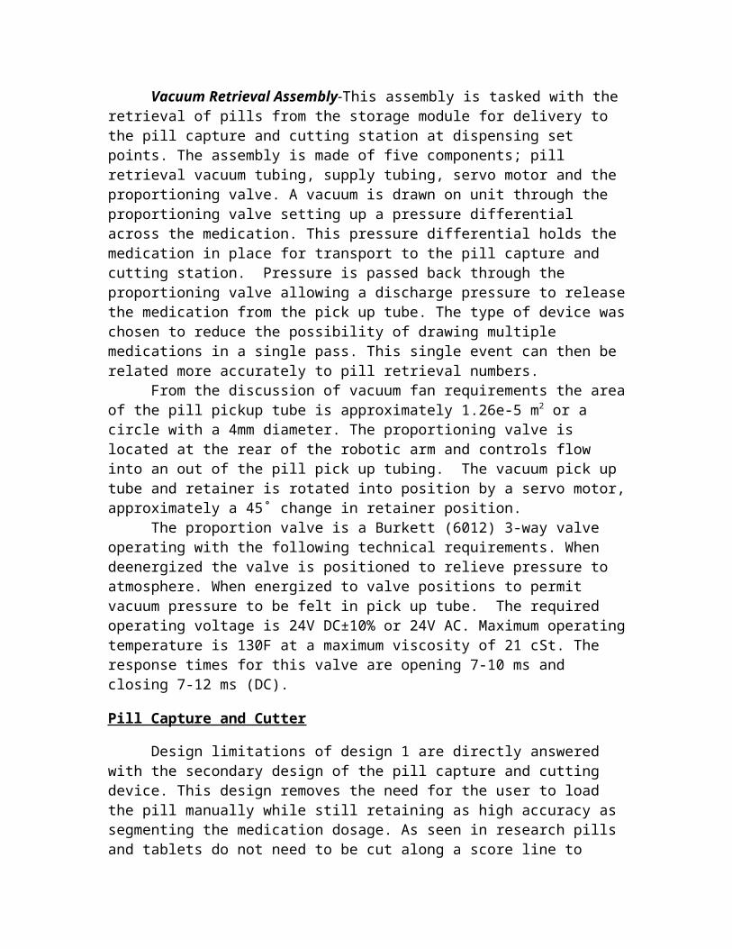
this action is given to the servo motor controller slaved to the PDA through the DAQ box on a single analog channel. The arm and second axis (containing the vacuum assembly) can be seen in the component breakdown illustration below. Further the action of the robotic arm unit is pictured below:
Vacuum Retrieval Assembly-This assembly is tasked with the retrieval of pills from the storage module for delivery to the pill capture and cutting station at dispensing set points. The assembly is made of five components; pill retrieval vacuum tubing, supply tubing, servo motor and the proportioning valve. A
Figure 6
Figure 5 Robotic arm
vacuum is drawn on unit through the proportioning valve setting up a pressure differential across the medication. This pressure differential holds the medication in place for transport to the pill capture and cutting station. Pressure is passed back through the proportioning valve allowing a discharge pressure to release the medication from the pick up tube. The type of device was chosen to reduce the possibility of drawing multiple medications in a single pass. This single event can then be related more accurately to pill retrieval numbers.
From the discussion of vacuum fan requirements the area of the pill pickup tube is approximately 1.26e-5 m2 or a circle with a 4mm diameter. The proportioning valve is located at the rear of the robotic arm and controls flow into an out of the pill pick up tubing. The vacuum pick up tube and retainer is rotated into position by a servo motor, approximately a 45˚ change in retainer position.
The proportion valve is a Burkett (6012) 3-way valve operating with the following technical requirements. When deenergized the valve is positioned to relieve pressure to atmosphere. When energized to valve positions to permit vacuum pressure to be felt in pick up tube. The required operating voltage is 24V DC±10% or 24V AC. Maximum operating temperature is 130F at a maximum viscosity of 21 cSt. The response times for this valve are opening 7-10 ms and closing 7-12 ms (DC).
Pill Capture and Cutter
Design limitations of design 1 are directly answered with the secondary design of the pill capture and cutting device. This design removes the need for the user to load the pill manually while still retaining as high accuracy as segmenting the medication dosage. As seen in research pills and tablets do not need to be cut along a score line to remain consistently segmented correctly. In fact personal research was conducted to cut tablets lengthwise with high accuracy. With this in mind the secondary design approach to pill capture and cutting is centered about geometry. Assuming all pills or tablets that shall be cut have a point of symmetry about them the capture swing arm shaped as an arc is capable of placing the point of contact between the pill and the swing arm about this center of symmetry. In the same motion align the cutter along this center of symmetry. This orientation allows a pill to be segmented in half, by repeating the process ¼ segments are achieved.
To examine the operation of this device a closer look into the geometry of the argument is needed. By looking at the complete circle and taking into account the changes in the x direction of the circle, a cosine wave form can be produced. The portion of this waveform of interest is from 0-90 degrees. Where 90 degrees is the minimum pill size relates to the maximum negative adjustment of the cutter assembly. Conversely, 0 degrees relates to the maximum pill size and zero cutter adjustment. By mechanically and continuously sampling the x position of the arc a direct connection is made to the adjustment of the cutter assembly.
In this device the arc and cutter assembly are not linked but rather in contact with one another. The set up of the cutter assembly places the blade of the cutter at the center point of the arc and the “feeler” side of the cutter in contact with the arc. A plumb line is drawn from the innermost portion of the
contact of the arc and cutter assembly. This plumb line extends a length slightly larger then the magnitude of the cutter adjustment. With each smaller pill the arc is rotated by torsion spring tension against a slight axial spin tension thereby positioning the pill to the center point. Concurrently the underside to the arc acted against the cutter “feeler” and spring tension (of cutter assembly) to reposition the cutter assembly. Note from previous discussion the changes in the x-direction of the arc are translated one for one to the cutter assembly. With this set up any symmetrical medication can be centered across the cutter blade providing accurate non-approximated center points.
While the positioning capability of this sub unit are key, this sub-unit contains or supports the major differentiating function of the overall device as well as provides a far superior design to design one. The functions of this assembly are to accept, capture, cut and deliver medication. Capture and cutting have already been covered in a preliminary seems. To evaluate the function of this sub assembly a complete sequence of operation should by addressed to understand the interconnection of devices. The assembly consists of a stepper motor, three ball bearing linear tracks, worm gear and pinion, torsion spring, two axial springs (one for the swing arm and one for the cutter assembly), base, cutter arm, stage, and sliding secondary stage.
Figure 7
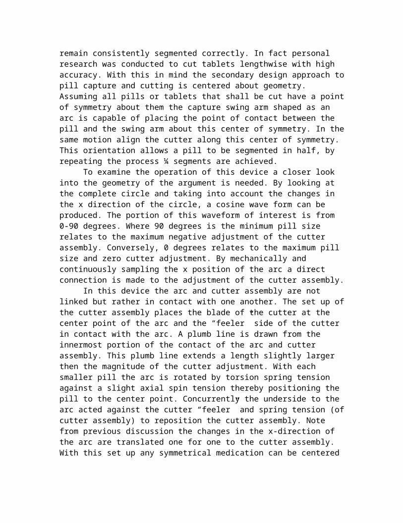
The base unit carries the weight of all components. The three ball bearing linear tracks are mounted parallel across the base perpendicular to the cutter arm. The main stage is mounted to the top two ball bearing linear tracks and is coupled to the worm gear shaft via treaded couplings. This permits the stage to project out from the base is the direction of the linear tracks by action of the
pinion gears coupled to the stepper motor. Noting the accuracy of the linear movement of the stage is not associated with the accuracy of the cuts. Rather the gearing is designed for higher rates of projection and retraction. Most important to this actuator is the ability to satisfy cutting conditions. Those conditions are that the stage is fully retracted and the arc is in contact with the cutter “feeler”. The base is also used to attach the cutter arm as well as routing power lines.
The main stage contains the swing arm and secondary stage. The action of the secondary stage is to slide open perpendicular to the motion of the main stage providing a means for removal of segmented medication. The action is provided through the main worm gear energy by coupling that energy to a slotted groove located at a hyper-extended region of the main stage. The hyper-extended range is at a distance equal to the maximum opening range of the secondary stage past to point of acceptance of medication. The most crucial component in the design is the swing arm. Balancing the load of three springs allows for the alignment of the cutter. To begin in the closed position the swing arm is at approximately 80 degrees (maximum negative adjustment). This position reduces the opening axial spring deformation while loading the cutter
Figure 8 Cutter Operation cycle
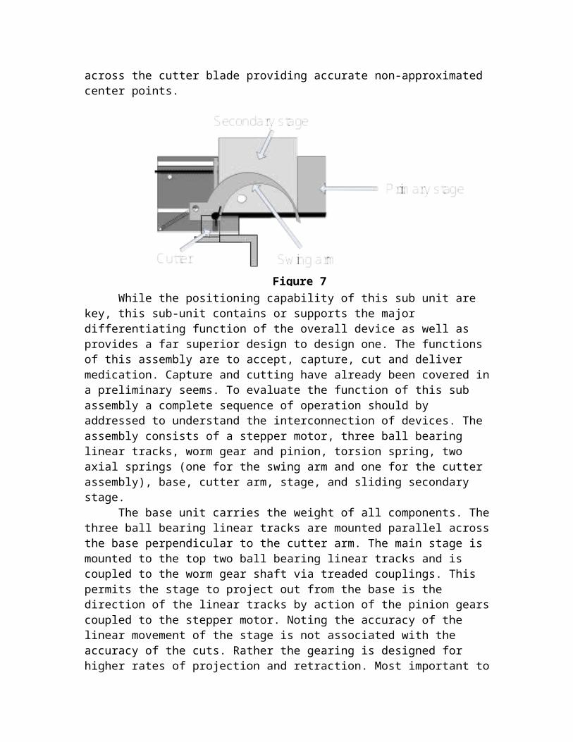
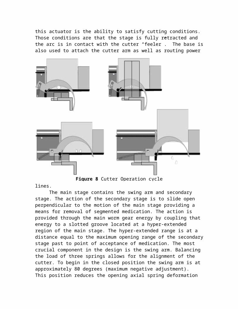
spring. The main stage is projected outward to the medication acceptance point where the opening spring force builds (assisted by the cutter spring) to open the swing arm against the torsion spring tension. At the medication acceptance located the swing arm is in the minimum adjustment position, providing the maximum area for deposition of the medication. After deposition of the medication the main stage is retracted. Now the torsion spring overcomes the opening spring and cutter spring tension due to the relaxed nature of the opening spring. This positions the medication and forces the cutter into position. At the fully retracted position the cutter is engaged after conditions met. The cutter is
operated through the use of a servo motor in contact with the cutter arm. Rotating of the servo forces the cutter arm shut against torsion spring tension in order to put force on the tablet. The blade is shaped as to pass by the retention arm and in between the swing arm. This cutter will not cut completely through the pill. Penetration of approximately 1/3 of the tablet thickness is required to cause a cut segmentation (determined experimentally with the use of a commercially available pill cutter.) Below is illustration of the cutter component breakdown and operation. At this time the main stage is again projected past the acceptance region to the dispensing region. To prevent damage to the opening spring a secondary spring with a spring constant lowered than the elastic region of the primary opening spring begins to give way. At this point the swing arm is balanced in the open position allowing the medication to be forced against the swing arm and off the secondary stage. The pills fall into an intermediate storage bin which rotates to a position outside the stage assembly. This rotations position another identical storage bin below the secondary stage. This operation is preformed to prevent confusion of segment sizes during subsequent segmentation (¼ segmentation) as well as facilitation for transport to the rejection assembly. The secondary stage movement is provided by a channel and pin assembly. The pin engages the channel just past the acceptance region and provides the anchor point for the stage to slide outward using the primary stepper motor energy.
Storage Assembly
Figure 9 Cutter Side View
Figure 10 Secondary Stage motion
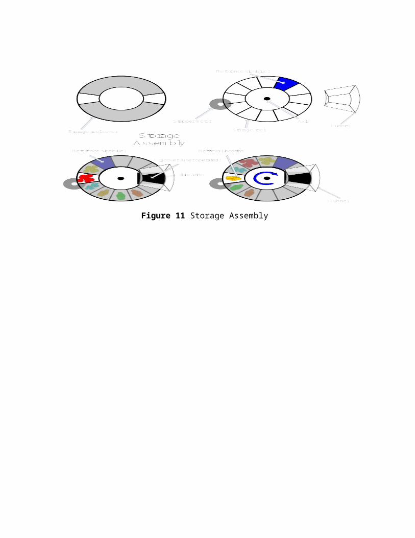
The storage assembly consists of a of a storage reel segmented into twelve containers, a storage reel cover, fill cover and stepper motor. The storage reel is designed based on a fishing tackle holder. The compartments within the storage reel are designed such that the outer edge of each compartment is deeper then the inner portion. Inner and outer depths are connected by a continual ramp. This allows the medication stored within the compartment to fall by gravity to the lowest position as medication is withdrawn. A reference slot, in blue, will provide the PDA with a reference position so that compartments can accurately be determined. Possibly the use of a limit switch will provide sufficient control over the outer edges of the primary compartment allowing the PDA to have an indication of storage reel position for reference. Rotation of the storage reel is controlled via a stepper motor mounted to the outer edge of the storage reel. During storage reel rotation the storage reel cover remains stationary. The reel cover contains two openings, one for withdrawal of medication by the arm and one for filling storage locations. To cover the fill location during operations a user operated fill cover is positioned over the fill location sliding out from below the fill funnel when needed.
Control of the stepper motor is accomplished through the use of a stepper motor controller slaved to the PDA through the DAQ. This requires the use of 3-4 four digital pins of the DAQ. Compartments are determined as a number of turns from the reference slot, this allows the PIC controller to retain positive control over the position of the compartment relative to opening. A potential draw back to this type of control is in the case of power loss. The stepper motor position will be unknown. To combat this situation the PDA will return the storage reel to the reference position and then reposition the reel to the proper opening. The storage assembly is pictured below showing the component exploded view on top and a typical rotation of the unit below.
Figure 11 Storage Assembly

PDA and LabVIEW
Using a PDA has many advantages. The dominating advantage is the storage capabilities. By incorporating a PDA into the dispensing device, a large amount of information can be stored without the risk of losing it if power outages occur. A data acquisition box will control the cutter and robotic arm however; the PDA allows a separate program to control the calendar, clock, timers, data storage, and initiation of the device’s actions.
The program for the device will be written in LabVIEW. It will act as the computational link between the data stored in Excel (also stored on the PDA) and the data acquisition device. It will track the number of pills dispensed and remaining and will control the timing of the alarms for expiration date and dispensing. The alarm and displays will output through the existing PDA screen and speaker.
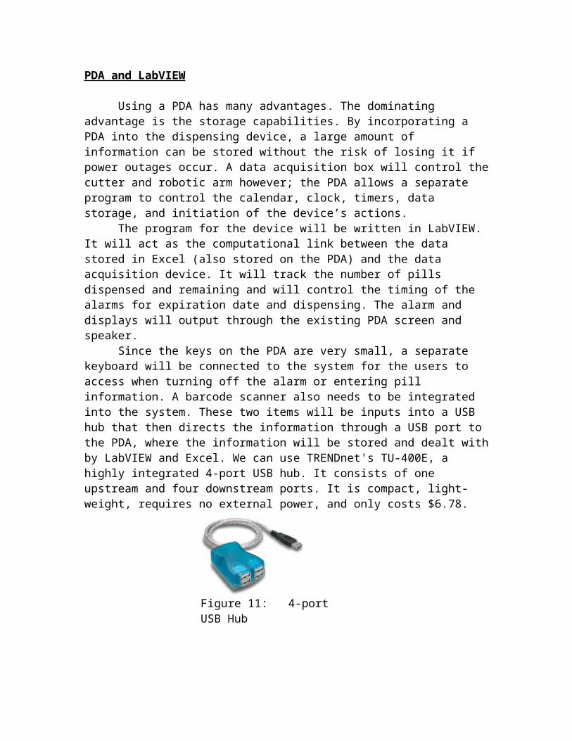
Since the keys on the PDA are very small, a separate keyboard will be connected to the system for the users to access when turning off the alarm or entering pill information. A barcode scanner also needs to be integrated into the system. These two items will be inputs into a USB hub that then directs the information through a USB port to the PDA, where the information will be stored and dealt with by LabVIEW and Excel. We can use TRENDnet's TU-400E, a highly integrated 4-port USB hub. It consists of one upstream and four downstream ports. It is compact, light-weight, requires no external power, and only costs $6.78.
The PDA chosen for this design is the Tungsten E2, made by Palm. It has non-volatile memory which means that the data will be safe even if the PDA runs completely out of battery power. Only palmOne models and the import Sharp Zaurus line of Linux PDAs are the only PDAs on the market to use 100% non-volatile memory. This feature is especially important because of the complicated process of storing and programming the dosage times and the need to keep a history of the pills dispensed. The Palm includes a calendar that we may incorporate into our timing and alarm functions. It saves energy by entering a sleeping mode, but will wake up to beep or vibrate. The PDA is also affordable at $150.
Figure 11: 4-port USB Hub

In order for the PDA to communicate with the motors, a data acquisition unit is required that will be connected to the PDA via a USB hub. Using 12 digital I/O lines, 8 analog input lines, 2 analog output lines and full speed USB interface the DAQ made by National Instruments (model number NI USB-6008) has plenty of capability for our needs. Nine of the digital input/output lines will be used to control the motors. The motors that control the cutter, temporary storage stage, robotic arm, and storage tray consist of two stepper motors and three servo motors. Three of these lines will control the function of the three servo motors; the other 6 lines will control the function of each of the stepper motors, 3 lines for each motor to control the output enable, direction, and speed. The digital output from the data acquisition device will be connected to each of the motors via a buffer circuit that will protect the data acquisition device as well alter the signal to meet the signal requirements of each of the motors. The data acquisition box will also accept inputs from the switches used to indicate when the motors have reached a home position. These signals will be accepted by the data acquisition device via the analog input ports. The LabVIEW program will translate these signals into a digital signal utilizing Boolean expressions. The DAQ, as well as the USB HUB and the PDA are all compatible with Windows 2000.
Figure 12: Tungsten E2 Palm PDA
Figure 13: Data Acquisition Device
Below is a flow diagram of data through the device.
Barcode Scanner
A barcoding system will be implemented to reduce errors during the loading process and to identify the stored data for each medication. Almost all prescriptions that come from the pharmacy utilize a barcode to link the medication to the patient's history, this ensures that the correct medication and dosage is being given to the patient. The medication dispenser will also utilize this UPC number provided by the pharmacy to store similar information on the PDA. The UPC number is simply a reference number that will correspond to a row of data in a Microsoft Word Excel spreadsheet that is stored in the PDA. This row of information will contain the UPC reference number, the number of pills stored in the module, the required dosage, the container number in which the pills will be stored, the number of times per day the medication should be dispensed, the time at which each dosage should be dispensed, the size the medication needs to be cut down to if necessary, and the expiration date. The information stored in the excel spreadsheet can then be used to track the medication within the LabVIEW program. This data will be pre-programmed in the device to reduce the amount of effort required by the user for initial set-up. When a prescription needs to be loaded the client will scan the prescription using the barcode scanner located on the device. The scanner uses a laser to scan the bars and measures the intensity of the light reflected via a photo diode which generates a waveform corresponding to the width of the bars and spaces. The decoder receives this wave and converts it to the 12 digit number that will be used as a reference
Figure 15 - IDAutomation USB Barcode Scanner
Figure 14: Flow of Data
number in our application. The keyboard wedge scanner chosen for this application is the IDAutomation Plug 'n Play USB Barcode Scanner. This particular scanner was chosen based on its easy installation process, USB connection which is compatible with the PDA, and built-in decoder which transmits the data as if it were typed from the keyboard. This scanner also does not require the use of any additional software, thus reducing the overall cost of the device and the amount of memory needed for the PDA. The scanner automatically inserts the 12 digit number wherever the cursor lies regardless of the program being used. When a client needs to reload the device, the barcode on the prescription is scanned. This code is then entered into the LabVIEW program and compared to each reference number stored in the excel spreadsheet. When a match between the scanned number and the reference numbers stored in the spreadsheet has been located, the LabVIEW program will withdraw the number of the storage module for that medication from the spreadsheet, and then activate the microcontroller to send a signal which will turn the storage container apparatus until the container with that assigned number is in the loading position. After more pills are added the LabVIEW program will prompt the user to enter in the number of pills added and the new expiration date using the keypad provided, and will store this new count and date into the excel spreadsheet. The program will then use the data of the spreadsheet indicating the size the pills needs to be to either move the pills to the cutting assembly or leave the pills in the storage assembly. The number of pills added that was entered by the client is then used to indicate the number of loops the cutting assembly must complete in order to cut all the medication. The spreadsheet will also provide the necessary information for dispensing of the medication. Where the time that the medication needs to be dispensed will prompt the dispensing portion of the LabVIEW program to run. The number of pills to be dispensed is also extracted from the excel spreadsheet, indicating the number of loops the program must perform, one loop for each pill dispensed. The use of the barcode system allows for the device to become more automated, thus reducing the possibility of human error. This reference number provides the necessary link between the LabVIEW program and the excel spreadsheet containing the data about each medication. If a barcoding system were not used, the client could easily forget which pill is located in which storage container, possibly loading a medication into the wrong container which will then cause that medication to be cut and dispensed incorrectly since the data from the medication previously stored in that container is being applied to the new medication. If the medications have different dispensing times and dosages, an error in the loading process can severely affect the health of the client and may even prove fatal. The use of the barcode minimizes the possibility of these errors occurring due to its high accuracy. The accurate reading of the barcode can be attributed to its start and stop characters as well as the checksum feature. The start and stop characters indicate where the code begins and ends which allows to machine to detect whether the code is being scanned forwards or backwards. This feature allows the user to scan the code without worrying the direction the

code is facing, thus reducing human error. The 12 digit number read from the barcode is also verified using the checksum number, which is the last digit of the code. This number is calculated by a series of computations using each of the individual digits of the 12 digit code. If the number calculated from the 12 digit number read by the scanner does not match the last digit on
the barcode, the number is discarded and the scanner re-reads the barcode. This feature again reduces error, ensuring that the number read by the scanner is the same number on the barcode.
Dispensing Assembly
The medication will be deposited into a container that is easily accessible to the client. Since the client must activate the device to begin the dispensing process after the alarm has sounded, a secondary guard, such as a trap door, against inadvertent exposure of the medication would be redundant and thus not necessary.

Pathway of the Pill

BUDGET
Below is the anticipated cost of the project based on the prices of the individual components:
Component Quantity Unit Price Extended Price Supplier
vacuum pump motor (donated) 1 $15.00 $0.00 dirt devil
vacuum impeller
(donated)1 $4.95 $0.00 dirt devil
Plexiglass 4 $15.00 $60.00 lyxnmotionPower Cord 1 $3.00 $3.00 Digikey
Actuator 1 $10.00 $10.00 DigikeyTracks with
rollers 4 $6.00 $24.00 BTI Supply
Brail dots (self adhesive) 1 $5.00 $5.00
PDA 1 $250.00 $150.00 Palm
USB Hub 1 $6.78 $6.78 TrednetData
Acquisition for USB
1 $145.00 $145.00 National Instruments
Wires & Electrical
components1 $100.00 $100.00 (Several)
Servos motor/stepper
motors6 $12.00 $72.00 lyxnmotion
Servo controller unit 1 $50.00 $50.00 lyxnmotion
Barcode reader 1 $120.00 $120.00 IDAutomation
Mechanical Components 1 $100.00 $100.00 (Several)
TOTAL (development) $845.78
APPENDIX
Appendix I – USB – 6008/6009 Device Block Diagram
(Source: http://www.ni.com/pdf/manuals/371303e.pdf)


