32
Selection Guide CENTERLINE 1500 Medium Voltage Motor Control Centers Designed for Intelligence, Safety, and Reliability

Selection Guide
CENTERLINE 1500 Medium Voltage Motor Control CentersDesigned for Intelligence, Safety, and Reliability

2 Rockwell Automation Publication 1500-SG001C-EN-P - January 2017
Medium Voltage Motor Control Centers ..................................... 3
Standard FeaturesFixed Mounted Vacuum Contactors ............................................. 5Non-Load Break Isolation Switch .................................................... 5
Intelligent Motor Control DevicesMotor Protection Relay ......................................................................... 7Differential Motor Protection Relay ............................................... 7E300 Electronic Overload Relay ....................................................... 8IntelliVAC Contactor Control Modules ........................................ 8
ArcShieldFeatures ....................................................................................................... 10
Medium Voltage Controller TypesOne-high FVNR Motor Starter ....................................................... 11Full Voltage Transformer Feeder Unit Starter ....................... 12 One-high Drive FVNR Motor Input Starter Controller .... 13Two-high FVNR Motor Starter ....................................................... 14 Two-high FV Transformer Feeder Unit Starter ..................... 15Two-high FVNR Drive Input Starter Controller .................... 16 Full Voltage Reversing (FVR) Motor Starter ............................ 17Two-speed Non-reversing Motor Starter ............................... 18 SMC Flex Smart Electronic Soft Start Motor Controller .... 20RVNR Autotransformer and Reactor Motor Starter .......... 23 Brush-type Synchronous Motor Starter ................................... 25Brushless Synchronous Motor Starter ...................................... 27
Incoming Line UnitsIncoming Line Units ............................................................................ 29Fused and Non-fused Load-break Switches ......................... 30
Your critical applications rely on medium voltage motors for safe, repeatable operation in harsh industrial environments. To help improve the protection and performance of your systems, choose Allen-Bradley® CENTERLINE® 1500 medium voltage motor control centers (MVMCCs)—built tough to meet your application demands.
Offering one of the broadest suites of motor controls in the marketplace, CENTERLINE 1500 MVMCCs deliver premium quality, tailored solutions in a centralized package that integrates control and power in one efficient solution.
Matched to your requirements, our UL and NEMA certified medium voltage solutions are designed to mitigate risk and support an extensive range of control formats and configurations. The result? Smart, cost-effective systems that can deliver power, control, information and safety capabilities on a common platform.
To extend system performance further, incorporate additional features—like industry-leading ArcShield™ arc resistant enclosures and IntelliCENTER® technology, our built-in network and software package. Our flexible and scalable approach to design means you can choose the capabilities you need to enhance safety and maximize productivity.
For nearly 80 years, Rockwell Automation has been providing leading medium voltage motor control solutions—solutions like the CENTERLINE 1500 MVMCC.
CENTERLINE 1500 Motor Control Centers

Medium Voltage Motor Control Centers
Rockwell Automation Publication 1500-SG001C-EN-P - January 2017 3
The CENTERLINE 1500 Medium Voltage Motor Control Centers (MVMCCs) robust structures consist of sections, wireways, doors, and mountable intelligent motor control (IMC) devices.
Enclosure FeaturesCENTERLINE 1500 MVMCCs come in an array of enclosure types, in compliance with multiple standards. These enclosures feature line, load and control wire conduit openings with removable cover plates for optimum accessibility and safety. All power cell doors are bolted for protection from the medium voltage power circuitry. Many of our enclosures can be ordered with a prepared space for future controller installations. For simplified installation, removable lifting angles and fixed base sill channels are provided.
Enclosure Types• Arc Resistant Type 2B, 40 or 50 kA (NEMA Type 12, IP52)• NEMA Type 1 – General purpose (IP10)• NEMA Type 1 w/g – General purpose with gasket (IP21)• NEMA Type 12 – Dust-tight and drip proof (IP52)• NEMA Type 3R – Non walk-in weatherproof (IP34)
Standards Compliance• Underwriters Laboratories, Inc. (UL), High Voltage
Industrial Control Equipment 347• Canadian Standards Association (CSA), Industrial Control
Equipment C22.2 No. 253 (harmonized with UL 347, fifth edition)
• National Electrical Manufacturers Association (NEMA), Medium Voltage Controllers Rated 1501 to 7200 VAC ICS 3-2 (formerly ICS 2-324)
• American Nation Standards Institute (ANSI), Instrument Transformers C57.13
• Institute of Electrical & Electronic Engineers (IEEE) 519-1992
• IEEE C37.20.7, Type 2B for arc resistance• National Electrical Code (NEC)• Canadian Electrical Code (CEC)• Occupational Safety & Health Act (OSHA)• European Directives for EMC
CompartmentalizationEach CENTERLINE 1500 MV MCC is assembled with completely isolated, easily accessible, and modular compartments:• Centerline power bus compartment• Medium voltage power cell compartment(s)• Low voltage compartment(s)
Power Bus Compartment
The CENTERLINE 1500 MVMCC features a centralized horizontal power bus compartment with removable cover plates for premium accessibility and power distribution throughout the entire lineup.• Controllers are
expandable from the left-to-right or right-to-left
• Designed for direct connection of incoming line cables, from top or bottom
• Horizontal edge-to-edge bus bar configuration opposes magnetic forces, moisture, and dust collection
• One-piece 3-phase bus brace reduces maintenance and provides superior distribution of forces during faults
• Side and rear access, protected by removable, bolted grounded plates; power bus accessible from the front for all motor controllers
Power Cell Compartment
The MVMCC power cell compartment is the heart of the controller. It contains all power circuitry, including proprietary non-load break isolation switches, integrated power fuses, contactors, and current and control power transformers. The MVMCC power cell compartment is fully interlocked (electrically and mechanically) to provide an enhanced safety level. Refer to “Standard Features” on page 5 for detailed information about our market leading technology.
Low Voltage Compartment
Power Cell Compartment
Power Bus Compartment
Medium Voltage Motor Control Centers
4 Rockwell Automation Publication 1500-SG001C-EN-P - January 2017
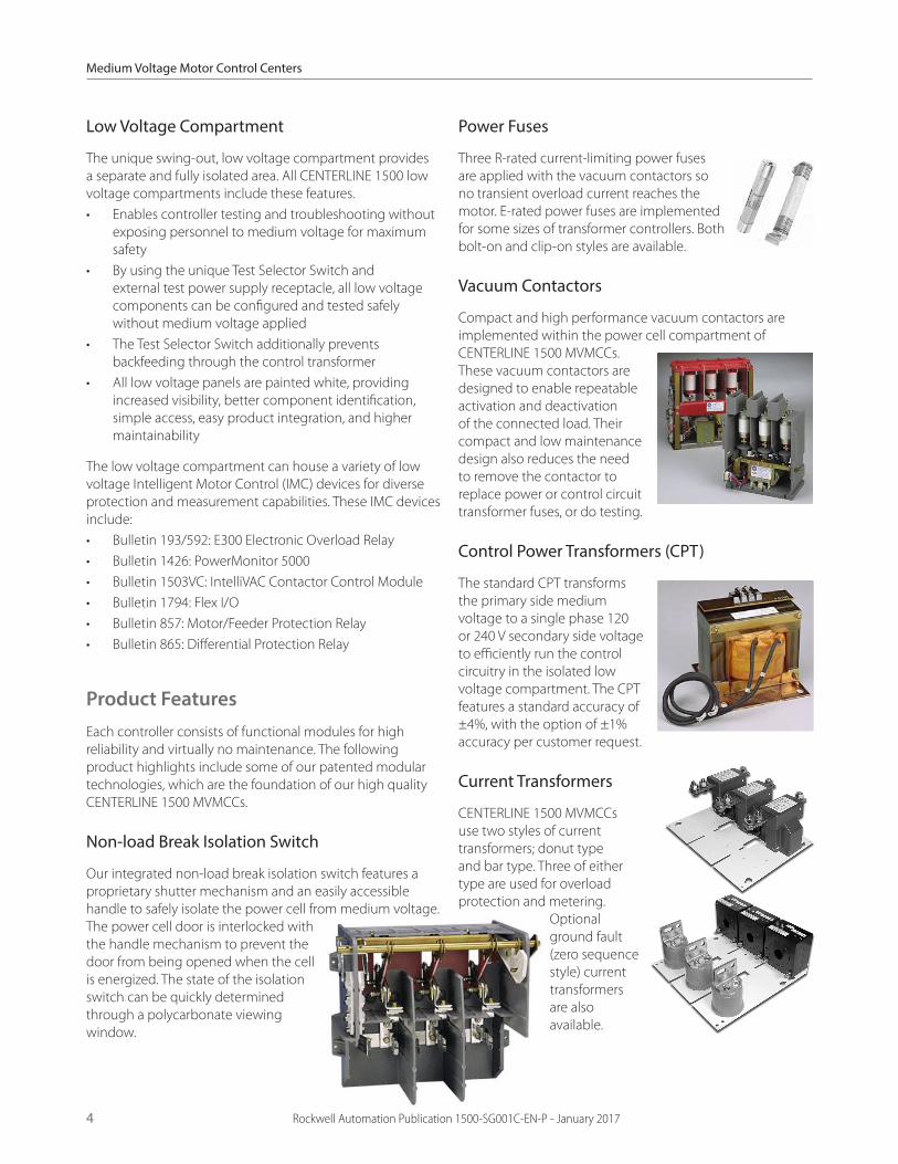
Low Voltage Compartment
The unique swing-out, low voltage compartment provides a separate and fully isolated area. All CENTERLINE 1500 low voltage compartments include these features.• Enables controller testing and troubleshooting without
exposing personnel to medium voltage for maximum safety
• By using the unique Test Selector Switch and external test power supply receptacle, all low voltage components can be configured and tested safely without medium voltage applied
• The Test Selector Switch additionally prevents backfeeding through the control transformer
• All low voltage panels are painted white, providing increased visibility, better component identification, simple access, easy product integration, and higher maintainability
The low voltage compartment can house a variety of low voltage Intelligent Motor Control (IMC) devices for diverse protection and measurement capabilities. These IMC devices include:• Bulletin 193/592: E300 Electronic Overload Relay• Bulletin 1426: PowerMonitor 5000• Bulletin 1503VC: IntelliVAC Contactor Control Module• Bulletin 1794: Flex I/O• Bulletin 857: Motor/Feeder Protection Relay• Bulletin 865: Differential Protection Relay
Product FeaturesEach controller consists of functional modules for high reliability and virtually no maintenance. The following product highlights include some of our patented modular technologies, which are the foundation of our high quality CENTERLINE 1500 MVMCCs.
Non-load Break Isolation Switch
Our integrated non-load break isolation switch features a proprietary shutter mechanism and an easily accessible handle to safely isolate the power cell from medium voltage. The power cell door is interlocked with the handle mechanism to prevent the door from being opened when the cell is energized. The state of the isolation switch can be quickly determined through a polycarbonate viewing window.
Power Fuses
Three R-rated current-limiting power fuses are applied with the vacuum contactors so no transient overload current reaches the motor. E-rated power fuses are implemented for some sizes of transformer controllers. Both bolt-on and clip-on styles are available.
Vacuum Contactors
Compact and high performance vacuum contactors are implemented within the power cell compartment of CENTERLINE 1500 MVMCCs. These vacuum contactors are designed to enable repeatable activation and deactivation of the connected load. Their compact and low maintenance design also reduces the need to remove the contactor to replace power or control circuit transformer fuses, or do testing.
Control Power Transformers (CPT)
The standard CPT transforms the primary side medium voltage to a single phase 120 or 240 V secondary side voltage to efficiently run the control circuitry in the isolated low voltage compartment. The CPT features a standard accuracy of ±4%, with the option of ±1% accuracy per customer request.
Current Transformers
CENTERLINE 1500 MVMCCs use two styles of current transformers; donut type and bar type. Three of either type are used for overload protection and metering.
Optional ground fault (zero sequence style) current transformers are also available.

Standard Features
Rockwell Automation Publication 1500-SG001C-EN-P - January 2017 5
Bulletin 1502
Fixed Mounted Vacuum Contactors The Allen-Bradley vacuum contactors are designed as fixed mounted devices for heavy-duty industrial performance. This design reduces the maintenance and reliability concerns associated with drawout-style contactors. Also, there are no drawout stab and finger assemblies, which require routine maintenance.
Our compact and low maintenance design reduces the need to remove the power cell. The contactors are designed to operate with Rockwell Automation’s IntelliVAC family of control modules or optional pilot relay-type control.
Advantages• Lightweight, compact design• Minimal maintenance required• High interrupting capability• Low chop current• Visual contact wear indicator (no measurement tools
required)• Mechanical interlocking to the non-load break isolation
switch• Excellent dielectric recovery allowing for high switching
frequency• Single coil/core magnet assembly (800 A only)• Control power transformer primary fuse holders (400 A
only)• All major components are easily accessed from the front• Mechanical latch design version (optional)• Easily integrated into control circuit with quick connector
and wire harness (optional)• Optimized to complement the advanced features of the
IntelliVAC contactor control module
Applications• Medium voltage (1,000 to 7,200V) vacuum switching
for motor starter loads (asynchronous, synchronous)
- Full voltage - Reduced voltage - Variable frequency drives
• Transformer feeder unit loads• Capacitor loads
Bulletin 1503
Non-Load Break Isolation SwitchThe isolation switch is a non-load-break type switch, available to support either clip-on or bolt-on fuses. When opened, the switch delivers a dead-fronted power cell for enhanced safety.
Positively driven auxiliary contacts provide safety interlocking of the low voltage control circuitry.
Electrical and mechanical interlocks help prevent the switch from opening or closing when the medium voltage vacuum contactor is energized, or if a power cell door is open.
Standard Features• 3 pole, gang operated• 400, 600 or 800 A full load current• Auxiliary contacts
- 2 N.O./2 N.C. are standard - Provisions for 3 N.O. /3 N.C.
• Contact type: Catalog No. 700-CPM• Contact Rating: NEMA 2 x A600 and
2 x P600• Clip-on or bolt-on fuses supported• Line and load fuse clips or bolt-on locations• Electrically and mechanically interlocked when used
with the Allen-Bradley handle module and contactor• Shutter mechanism fully isolates the power cell from
medium voltage power bus• Switch blades are grounded in the off position
Mechanical Interlocking• A simple, heavy duty, direct drive mechanism improves
reliability and helps provide superior operator safety• All mechanical interlock mechanisms remain part of the
enclosure to minimize setup adjustment
Isolation Switch Handle Module• Padlocking provision up to 3 padlocks in open position,
1 padlock in closed position• Mechanical interlock with the power
cell door, non-load isolation switch, and contactor
• Provision for mechanically trapped key interlocking
Fixed Mounted Vacuum
Contactors
Standard Features
6 Rockwell Automation Publication 1500-SG001C-EN-P - January 2017
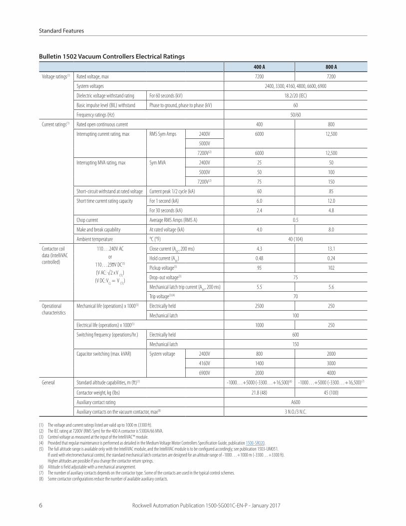
Bulletin 1502 Vacuum Controllers Electrical Ratings
400 A 800 A
Voltage ratings(1) Rated voltage, max 7200 7200
System voltages 2400, 3300, 4160, 4800, 6600, 6900
Dielectric voltage withstand rating For 60 seconds (kV) 18.2/20 (IEC)
Basic impulse level (BIL) withstand Phase to ground, phase to phase (kV) 60
Frequency ratings (Hz) 50/60
Current ratings(1) Rated open continuous current 400 800
Interrupting current rating, max RMS Sym Amps 2400V 6000 12,500
5000V
7200V(2) 6000 12,500
Interrupting MVA rating, max Sym MVA 2400V 25 50
5000V 50 100
7200V(2) 75 150
Short-circuit withstand at rated voltage Current peak 1/2 cycle (kA) 60 85
Short time current rating capacity For 1 second (kA) 6.0 12.0
For 30 seconds (kA) 2.4 4.8
Chop current Average RMS Amps (RMS A) 0.5
Make and break capability At rated voltage (kA) 4.0 8.0
Ambient temperature °C (°F) 40 (104)
Contactor coil data (IntelliVAC controlled)
110…240V ACor
110…250V DC(3)
(V AC: √2 x V CTL
)(V DC: V
CL = V
CTL)
Close current (ADC
, 200 ms) 4.3 13.1
Hold current (ADC
) 0.48 0.24
Pickup voltage(3) 95 102
Drop-out voltage(3) 75
Mechanical latch trip current (ADC
, 200 ms) 5.5 5.6
Trip voltage(3)(4) 70
Operational characteristics
Mechanical life (operations) x 1000(5) Electrically held 2500 250
Mechanical latch 100
Electrical life (operations) x 1000(5) 1000 250
Switching frequency (operations/hr.) Electrically held 600
Mechanical latch 150
Capacitor switching (max. kVAR) System voltage 2400V 800 2000
4160V 1400 3000
6900V 2000 4000
General Standard altitude capabilities, m (ft)(1) -1000…+5000 (-3300…+16,500)(6) -1000…+5000 (-3300…+16,500)(7)
Contactor weight, kg (lbs) 21.8 (48) 45 (100)
Auxiliary contact rating A600
Auxiliary contacts on the vacuum contactor, max(8) 3 N.O./3 N.C.
(1) The voltage and current ratings listed are valid up to 1000 m (3300 ft). (2) The IEC rating at 7200V (RMS Sym) for the 400 A contactor is 5300A/66 MVA.(3) Control voltage as measured at the input of the IntelliVAC™ module.(4) Provided that regular maintenance is performed as detailed in the Medium Voltage Motor Controllers Specification Guide, publication 1500-SR020.(5) The full altitude range is available only with the IntelliVAC module, and the IntelliVAC module is to be configured accordingly; see publication 1503-UM051.
If used with electromechanical control, the standard mechanical latch contactors are designed for an altitude range of -1000…+1000 m (-3300…+3300 ft). Higher altitudes are possible if you change the contactor return springs.
(6) Altitude is field adjustable with a mechanical arrangement.(7) The number of auxiliary contacts depends on the contactor type. Some of the contacts are used in the typical control schemes.(8) Some contactor configurations reduce the number of available auxiliary contacts.
Intelligent Motor Control Devices
Rockwell Automation Publication 1500-SG001C-EN-P - January 2017 7
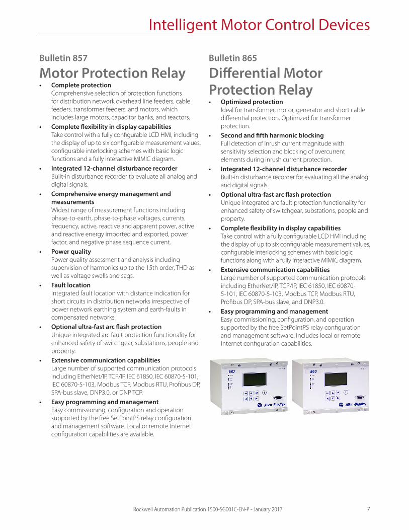
Bulletin 857
Motor Protection Relay• Complete protection
Comprehensive selection of protection functions for distribution network overhead line feeders, cable feeders, transformer feeders, and motors, which includes large motors, capacitor banks, and reactors.
• Complete flexibility in display capabilities Take control with a fully configurable LCD HMI, including the display of up to six configurable measurement values, configurable interlocking schemes with basic logic functions and a fully interactive MIMIC diagram.
• Integrated 12-channel disturbance recorder Built-in disturbance recorder to evaluate all analog and digital signals.
• Comprehensive energy management and measurements Widest range of measurement functions including phase-to-earth, phase-to-phase voltages, currents, frequency, active, reactive and apparent power, active and reactive energy imported and exported, power factor, and negative phase sequence current.
• Power quality Power quality assessment and analysis including supervision of harmonics up to the 15th order, THD as well as voltage swells and sags.
• Fault location Integrated fault location with distance indication for short circuits in distribution networks irrespective of power network earthing system and earth-faults in compensated networks.
• Optional ultra-fast arc flash protection Unique integrated arc fault protection functionality for enhanced safety of switchgear, substations, people and property.
• Extensive communication capabilities Large number of supported communication protocols including EtherNet/IP, TCP/IP, IEC 61850, IEC 60870-5-101, IEC 60870-5-103, Modbus TCP, Modbus RTU, Profibus DP, SPA-bus slave, DNP3.0, or DNP TCP.
• Easy programming and management Easy commissioning, configuration and operation supported by the free SetPointPS relay configuration and management software. Local or remote Internet configuration capabilities are available.
Bulletin 865
Differential Motor Protection Relay• Optimized protection
Ideal for transformer, motor, generator and short cable differential protection. Optimized for transformer protection.
• Second and fifth harmonic blocking Full detection of inrush current magnitude with sensitivity selection and blocking of overcurrent elements during inrush current protection.
• Integrated 12-channel disturbance recorder Built-in disturbance recorder for evaluating all the analog and digital signals.
• Optional ultra-fast arc flash protection Unique integrated arc fault protection functionality for enhanced safety of switchgear, substations, people and property.
• Complete flexibility in display capabilities Take control with a fully configurable LCD HMI including the display of up to six configurable measurement values, configurable interlocking schemes with basic logic functions along with a fully interactive MIMIC diagram.
• Extensive communication capabilities Large number of supported communication protocols including EtherNet/IP, TCP/IP, IEC 61850, IEC 60870-5-101, IEC 60870-5-103, Modbus TCP, Modbus RTU, Profibus DP, SPA-bus slave, and DNP3.0.
• Easy programming and management Easy commissioning, configuration, and operation supported by the free SetPointPS relay configuration and management software. Includes local or remote Internet configuration capabilities.
Intelligent Motor Control Devices
8 Rockwell Automation Publication 1500-SG001C-EN-P - January 2017
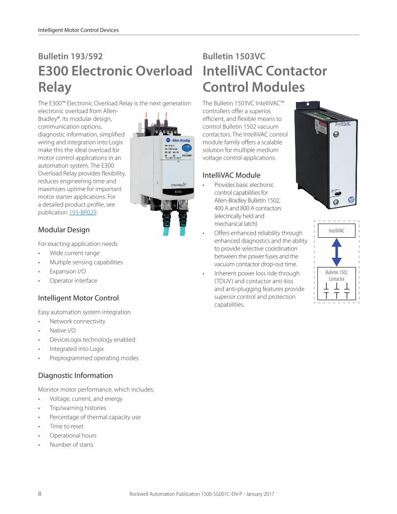
Bulletin 193/592
E300 Electronic Overload RelayThe E300™ Electronic Overload Relay is the next generation electronic overload from Allen-Bradley®. Its modular design, communication options, diagnostic information, simplified wiring and integration into Logix make this the ideal overload for motor control applications in an automation system. The E300 Overload Relay provides flexibility, reduces engineering time and maximizes uptime for important motor starter applications. For a detailed product profile, see publication 193-BR029.
Modular Design
For exacting application needs• Wide current range• Multiple sensing capabilities• Expansion I/O• Operator interface
Intelligent Motor Control
Easy automation system integration• Network connectivity• Native I/O• DeviceLogix technology enabled• Integrated into Logix• Preprogrammed operating modes
Diagnostic Information
Monitor motor performance, which includes:• Voltage, current, and energy• Trip/warning histories• Percentage of thermal capacity use• Time to reset• Operational hours• Number of starts
Bulletin 1503VC
IntelliVAC Contactor Control ModulesThe Bulletin 1503VC IntelliVAC™ controllers offer a superior, efficient, and flexible means to control Bulletin 1502 vacuum contactors. The IntelliVAC control module family offers a scalable solution for multiple medium voltage control applications.
IntelliVAC Module• Provides basic electronic
control capabilities for Allen-Bradley Bulletin 1502, 400 A and 800 A contactors (electrically held and mechanical latch)
• Offers enhanced reliability through enhanced diagnostics and the ability to provide selective coordination between the power fuses and the vacuum contactor drop-out time.
• Inherent power loss ride through (TDUV) and contactor anti-kiss and anti-plugging features provide superior control and protection capabilities.
IntelliVAC
Bulletin 1502 Contactor

Intelligent Motor Control Devices
Rockwell Automation Publication 1500-SG001C-EN-P - January 2017 9
Bulletin 1503VC IntelliVAC Control Modules
Cat. No.
Description
1503VC-BMC5 IntelliVAC electrically held and mechanical latch
Bulletin 1503VC IntelliVAC Control Module Electrical Ratings and Approvals
Contactor Ratings (Amps)
Control Voltage (AC or DC)
AC Rating
DC Rating
Main input voltage 110…240 V rms, +10/-15%, 47…63 Hz
110…250 V, +10/-15%
Main input current Inrush 400/800 120/240 25A peak (1/2 cycle) 25A
Idle 125 mA 35 mA
Hold (max) 300 mA 4.9A
Close (0.2 s)
400 120 4.6A 100 mA
240 3.4A
800 120 11.3A
240 8.9A
Latch trip (0.2 s)
400 120 7.0A 3.8A
240 3.6A
800 120 7.0A
240 4.3A
Command inputs 70…240 V, rms 70…250 V
Output contacts 250V rms, 5A, R load; 2A (reactive), PF = 0.4
30V, 5A, R load; 2A (reactive), L/R = 7 ms
Standards and approval cULus, UL, CSA, IEC, CE
(1) All AC values are rms, except where noted. (2) The maximum currents shown are for either the Bulletin 1502 400A or 800A vacuum contactors.
Close current duration is 200 milliseconds.(3) Applicable only to mechanical latch contactors.
ArcShield Technology
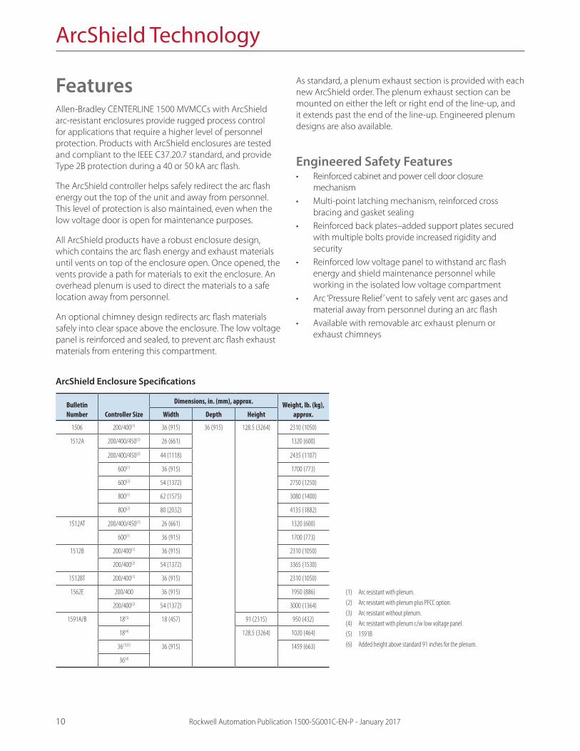
FeaturesAllen-Bradley CENTERLINE 1500 MVMCCs with ArcShield arc-resistant enclosures provide rugged process control for applications that require a higher level of personnel protection. Products with ArcShield enclosures are tested and compliant to the IEEE C37.20.7 standard, and provide Type 2B protection during a 40 or 50 kA arc flash.
The ArcShield controller helps safely redirect the arc flash energy out the top of the unit and away from personnel. This level of protection is also maintained, even when the low voltage door is open for maintenance purposes.
All ArcShield products have a robust enclosure design, which contains the arc flash energy and exhaust materials until vents on top of the enclosure open. Once opened, the vents provide a path for materials to exit the enclosure. An overhead plenum is used to direct the materials to a safe location away from personnel.
An optional chimney design redirects arc flash materials safely into clear space above the enclosure. The low voltage panel is reinforced and sealed, to prevent arc flash exhaust materials from entering this compartment.
As standard, a plenum exhaust section is provided with each new ArcShield order. The plenum exhaust section can be mounted on either the left or right end of the line-up, and it extends past the end of the line-up. Engineered plenum designs are also available.
Engineered Safety Features• Reinforced cabinet and power cell door closure
mechanism• Multi-point latching mechanism, reinforced cross
bracing and gasket sealing• Reinforced back plates–added support plates secured
with multiple bolts provide increased rigidity and security
• Reinforced low voltage panel to withstand arc flash energy and shield maintenance personnel while working in the isolated low voltage compartment
• Arc ‘Pressure Relief’ vent to safely vent arc gases and material away from personnel during an arc flash
• Available with removable arc exhaust plenum or exhaust chimneys
10 Rockwell Automation Publication 1500-SG001C-EN-P - January 2017
ArcShield Enclosure Specifications
Bulletin Number Controller Size
Dimensions, in. (mm), approx. Weight, lb. (kg), approx.Width Depth Height
1506 200/400(1) 36 (915) 36 (915) 128.5 (3264) 2310 (1050)
1512A 200/400/450(1) 26 (661) 1320 (600)
200/400/450(2) 44 (1118) 2435 (1107)
600(1) 36 (915) 1700 (773)
600(2) 54 (1372) 2750 (1250)
800(1) 62 (1575) 3080 (1400)
800(2) 80 (2032) 4135 (1882)
1512AT 200/400/450(1) 26 (661) 1320 (600)
600(1) 36 (915) 1700 (773)
1512B 200/400(1) 36 (915) 2310 (1050)
200/400(2) 54 (1372) 3365 (1530)
1512BT 200/400(1) 36 (915) 2310 (1050)
1562E 200/400 36 (915) 1950 (886)
200/400(2) 54 (1372) 3000 (1364)
1591A/B 18(3) 18 (457) 91 (2315) 950 (432)
18(4) 128.5 (3264) 1020 (464)
36(1)(5) 36 (915) 1459 (663)
36(4)
(1) Arc resistant with plenum. (2) Arc resistant with plenum plus PFCC option.(3) Arc resistant without plenum.(4) Arc resistant with plenum c/w low voltage panel.(5) 1591B(6) Added height above standard 91 inches for the plenum.

Medium Voltage Controller Types
Rockwell Automation Publication 1500-SG001C-EN-P - January 2017 11
Bulletin 1512A
One-high Full Voltage Non-reversing Motor StarterDescription of Features• Fixed mounted vacuum contactor• Three-pole, gang-operated, non-load break isolating
switch with an external operating handle, fully interlocked with main contactor and power cell doors
• A polycarbonate viewing window in the power cell door to view the position of the isolating switch
• Three R-rated current-limiting power fuses• Three current transformers• Control power transformer with primary and secondary
fuses
• Segregated low voltage panel to house standard and optional hardware for unit control and monitoring
• IntelliVAC control module for each vacuum contactor, mounted in low voltage panel, with advanced features
• Additional low voltage control panel accessories that include:
- ‘NORMAL-OFF-TEST’ circuit - receptacle for external test
power supply - set of control circuit terminal
blocks• Two-high structure design for two complete motor
controllers• Available in optional ArcShield enclosure• Also available as ‘Prepared Space’ (Bulletin 1512BP) and
Starter Kits (Bulletin 1512BS)
Bulletin 1512A Starter Specifications
Starter Size
HP, max Dimensions, in. (mm), approx. Weight, lb. (kg), approx.2400V 3300V 4160V 4800V 6600V 6900V Width Depth Height
200 A 800 1000 1250 1500 2250 2500 26 (661) 36 (915) 91 (2315)(1) 1075 (490)(2)
400 A 1500 2250 2750 3000 4500 5000
450 A 1750 2500 3000 3500 6500 36 (915)
600 A 2750 3500 4500 5500 8000 1350 (611)(2)
800 A 3000 5000 6000 7000 9000 56 (1422) 1800 (816)
(1) Height is 128.5 inches (3264 mm) with ArcShield enclosure with plenum.(2) Weight is different with ArcShield.
Bulletin 1512A Power Circuit Schematic
L1 L2 L3 GNDIS
F1
F1
F1
F2 F2
GFCT(optional)
CPT1
CT1
CT2
CT3
T1
T2
T3
M
BLK
5
W
M
Medium Voltage Controller Types
12 Rockwell Automation Publication 1500-SG001C-EN-P - January 2017
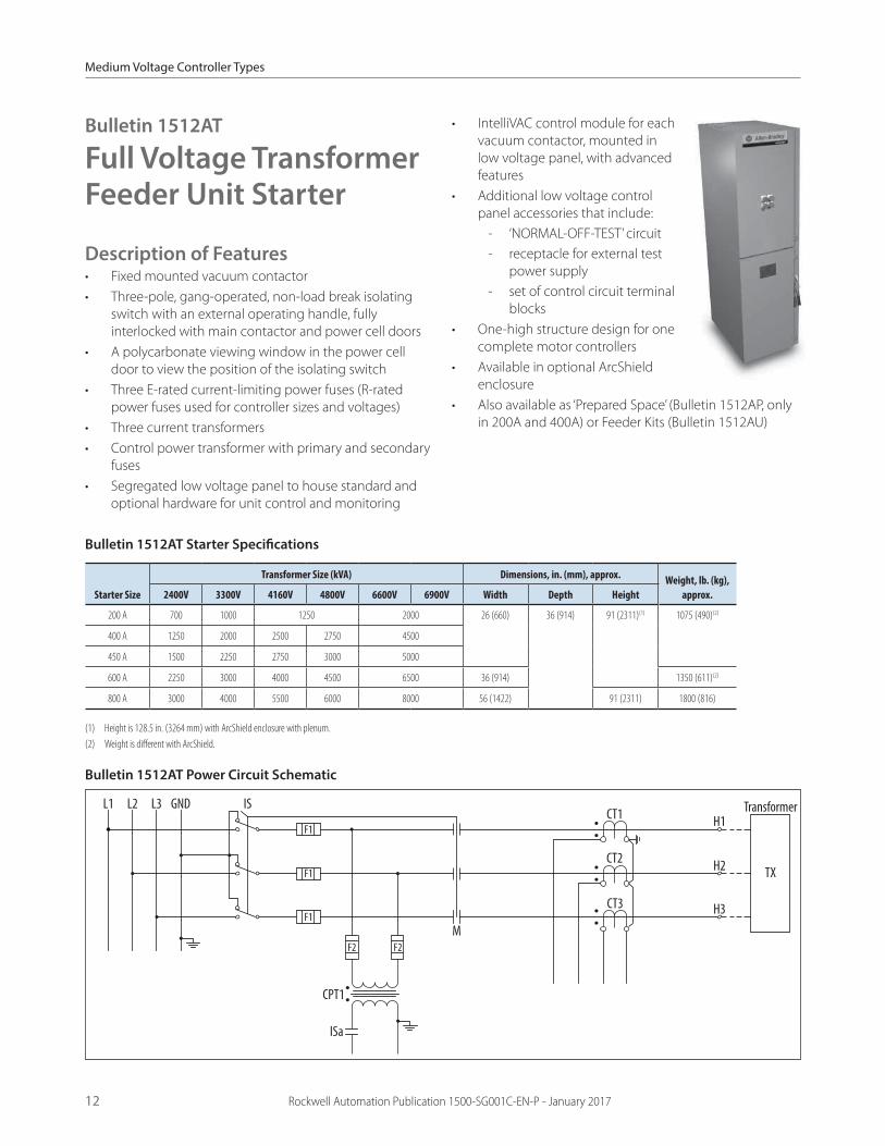
Bulletin 1512AT
Full Voltage Transformer Feeder Unit Starter
Description of Features• Fixed mounted vacuum contactor• Three-pole, gang-operated, non-load break isolating
switch with an external operating handle, fully interlocked with main contactor and power cell doors
• A polycarbonate viewing window in the power cell door to view the position of the isolating switch
• Three E-rated current-limiting power fuses (R-rated power fuses used for controller sizes and voltages)
• Three current transformers• Control power transformer with primary and secondary
fuses• Segregated low voltage panel to house standard and
optional hardware for unit control and monitoring
• IntelliVAC control module for each vacuum contactor, mounted in low voltage panel, with advanced features
• Additional low voltage control panel accessories that include:
- ‘NORMAL-OFF-TEST’ circuit - receptacle for external test
power supply - set of control circuit terminal
blocks• One-high structure design for one
complete motor controllers• Available in optional ArcShield
enclosure• Also available as ‘Prepared Space’ (Bulletin 1512AP, only
in 200A and 400A) or Feeder Kits (Bulletin 1512AU)
Bulletin 1512AT Starter Specifications
Starter Size
Transformer Size (kVA) Dimensions, in. (mm), approx. Weight, lb. (kg), approx.2400V 3300V 4160V 4800V 6600V 6900V Width Depth Height
200 A 700 1000 1250 2000 26 (660) 36 (914) 91 (2311)(1) 1075 (490)(2)
400 A 1250 2000 2500 2750 4500
450 A 1500 2250 2750 3000 5000
600 A 2250 3000 4000 4500 6500 36 (914) 1350 (611)(2)
800 A 3000 4000 5500 6000 8000 56 (1422) 91 (2311) 1800 (816)
(1) Height is 128.5 in. (3264 mm) with ArcShield enclosure with plenum.(2) Weight is different with ArcShield.
Bulletin 1512AT Power Circuit Schematic
L1 L2 L3 GND IS
ISa
F1
F1
F1
F2 F2
CPT1
CT1
CT2
CT3
H1
TX
Transformer
H2
H3
M

Medium Voltage Controller Types
Rockwell Automation Publication 1500-SG001C-EN-P - January 2017 13
Bulletin 1512AD
One-high Full Voltage Non-reversing Drive Input Starter Controller
Description of Features• Fixed mounted vacuum contactor• Three-pole, gang-operated, non-load break isolating
switch with an external operating handle, fully interlocked with main contactor and power cell doors
• A polycarbonate viewing window in the power cell door to view the position of the isolating switch
• Three current-limiting power fuses• Three current transformers
• Segregated low voltage panel to house circuit control fusing that includes:
- ‘NORMAL-OFF-TEST’ circuit - receptacle for external test power supply - set of control circuit terminal blocks - optional hardware for unit control and monitoring
• IntelliVAC control module for each vacuum contactor, mounted in low voltage panel, with advanced features:
- selectable vacuum contactor drop-out time and consistent pickup time
- altitude compensation - anti-kiss and anti-plugging protection - set of control circuit terminal blocks
• Unit output must be cabled to VFD input. Customer is responsible for interwiring between input contactor unit and variable frequency drive (VFD)
Bulletin 1512AD Starter Specifications
Starter Size
Transformer Size (kVA)(1) Dimensions, in. (mm), approx. Weight, lb. (kg), approx.(3)2400 V 3300 V 4160 V 4800 V 6600 V 6900 V Width Depth Height
200A 700 1000 1250 2000 26 (660) 36 (914) 91 (2311)(2) 1075 (488)
400A 1250 2000 2500 2750 4500
600A 1500 2250 2750 3000 N/A 36 (914) 1350 (611)
800A 2250 3000 4000 4500 56 (1423) 1800 (816)
(1) Sized by VFD and continuous current of motor.(2) Height is 128.5 in. (3264 mm) with ArcShield enclosure with plenum.(3) Weight is different with ArcShield.
Bulletin 1512AD Power Circuit Schematic
L1 L2 L3 GND IS
ISa
F1
F1
F1
F2 F2
CPT1
CT1
CT2
CT3
H1MediumVoltageVariable
FrequencyDrive
(MV VFD)
H2
H3
M

Medium Voltage Controller Types
14 Rockwell Automation Publication 1500-SG001C-EN-P - January 2017
Bulletin 1512B Starter Specifications
Starter Size
HP, max Dimensions, in. (mm), approx. Weight, lb. (kg), approx.2400V 3300V 4160V 4800V 6600V 6900V Width Depth Height
200 A 800 1000 1250 1500 2250 2500 36 (915) 36 (915) 91 (2315)(1) 1770 (802)(2)
400 A 1500 2250 2750 3000 4000 4000
(1) Height is 128.5 inches (3264 mm) with ArcShield enclosure with plenum.(2) Weight is different with ArcShield.
Bulletin 1512B Power Circuit Schematic
L1 L2 L3 GND IS
F1
F1
F1
F2 F2
GFCT(optional)
CPT1
CT1
CT2
CT3
T1
T2
T3
M
BLK W
M
Bulletin 1512B
Two-high Full Voltage Non-reversing Motor Starter
Description of Features• Fixed mounted vacuum contactor• Three-pole, gang-operated, non-load break isolating
switch with an external operating handle, fully interlocked with main contactor and power cell doors
• A polycarbonate viewing window in the power cell door to view the position of the isolating switch
• Three R-rated current-limiting power fuses• Three current transformers• Control power transformer with primary and secondary
fuses
• Segregated low voltage panel to house standard and optional hardware for unit control and monitoring
• IntelliVAC control module for each vacuum contactor, mounted in low voltage panel, with advanced features
• Additional low voltage control panel accessories that include:
- ‘NORMAL-OFF-TEST’ circuit - receptacle for external test
power supply - set of control circuit
terminal blocks• Two-high structure design for two complete motor
controllers• Available in optional ArcShield enclosure• Also available as ‘Prepared Space’ (Bulletin 1512BP) and
Starter Kits (Bulletin 1512BS)

Medium Voltage Controller Types
Rockwell Automation Publication 1500-SG001C-EN-P - January 2017 15
Bulletin 1512BT
Two-high Full Voltage Transformer Feeder Unit Starter
Description of Features• Fixed mounted vacuum contactor• Three-pole, gang-operated, non-load break isolating
switch with an external operating handle, fully interlocked with main contactor and power cell doors
• A polycarbonate viewing window in the power cell door to view the position of the isolating switch
• Three E-rated or R-rated current-limiting power fuses• Three current transformers• Control power transformer with primary and secondary
fuses
• Segregated low voltage panel to house standard and optional hardware for unit control and monitoring
• IntelliVAC control module for each vacuum contactor, mounted in low voltage panel, with advanced features
• Additional low voltage control panel accessories that include:
- ‘NORMAL-OFF-TEST’ circuit
- receptacle for external test power supply
- set of control circuit terminal blocks
• Two-high structure design for one complete motor controllers
• Available in optional ArcShield enclosure• Also available as ‘Prepared Space’ (Bulletin 1512BP) or
Starter Kit (Bulletin 1512BU)
Bulletin 1512BT Starter Specifications
Starter Size
Transformer Size (kVA) Dimensions, in. (mm), approx. Weight, lb. (kg), approx.2400V 3300V 4160V 4800V 6600V 6900V Width Depth Height
200 A 700 1000 1250 2000 36 (914) 36 (914) 91 (2311)(1) 1770 (802)(2)
400 A 1500 2000 2500 2750 4000
(3) Height is 128.5 in. (3264 mm) with ArcShield enclosure with plenum.(4) Weight is different with ArcShield.
Bulletin 1512BT Power Circuit Schematic
L1 L2 L3 GND IS
ISa
F1
F1
F1
F2 F2
CPT1
CT1
CT2
CT3
H1
TX
Transformer
H2
H3
M
Medium Voltage Controller Types
16 Rockwell Automation Publication 1500-SG001C-EN-P - January 2017
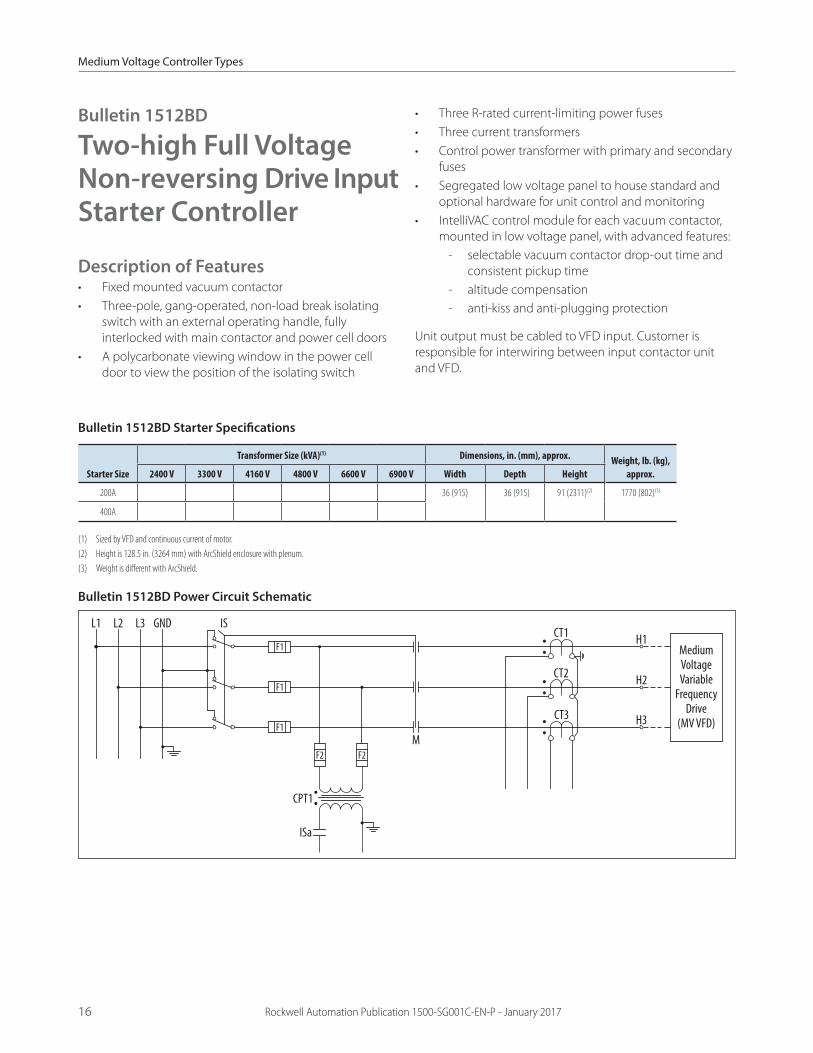
Bulletin 1512BD Starter Specifications
Starter Size
Transformer Size (kVA)(1) Dimensions, in. (mm), approx. Weight, lb. (kg), approx.2400 V 3300 V 4160 V 4800 V 6600 V 6900 V Width Depth Height
200A 700 1000 1250 2000 36 (915) 336 (915) 91 (2311)(2) 1770 (802)(3)
400A 1250 2000 2500 2750 4500
(1) Sized by VFD and continuous current of motor.(2) Height is 128.5 in. (3264 mm) with ArcShield enclosure with plenum.(3) Weight is different with ArcShield.
Bulletin 1512BD Power Circuit Schematic
L1 L2 L3 GND IS
ISa
F1
F1
F1
F2 F2
CPT1
CT1
CT2
CT3
H1MediumVoltageVariable
FrequencyDrive
(MV VFD)
H2
H3
M
Bulletin 1512BD
Two-high Full Voltage Non-reversing Drive Input Starter Controller
Description of Features• Fixed mounted vacuum contactor• Three-pole, gang-operated, non-load break isolating
switch with an external operating handle, fully interlocked with main contactor and power cell doors
• A polycarbonate viewing window in the power cell door to view the position of the isolating switch
• Three R-rated current-limiting power fuses• Three current transformers• Control power transformer with primary and secondary
fuses• Segregated low voltage panel to house standard and
optional hardware for unit control and monitoring• IntelliVAC control module for each vacuum contactor,
mounted in low voltage panel, with advanced features: - selectable vacuum contactor drop-out time and
consistent pickup time - altitude compensation - anti-kiss and anti-plugging protection
Unit output must be cabled to VFD input. Customer is responsible for interwiring between input contactor unit and VFD.
Medium Voltage Controller Types
Rockwell Automation Publication 1500-SG001C-EN-P - January 2017 17
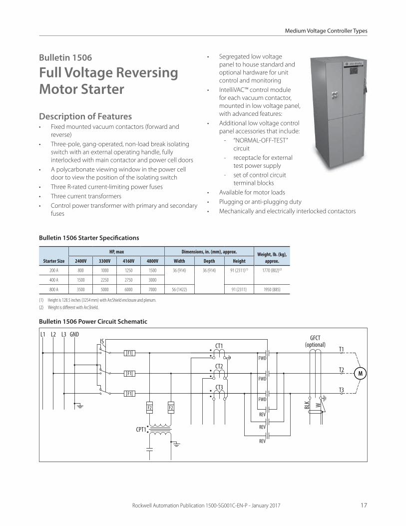
Bulletin 1506
Full Voltage Reversing Motor Starter
Description of Features• Fixed mounted vacuum contactors (forward and
reverse)• Three-pole, gang-operated, non-load break isolating
switch with an external operating handle, fully interlocked with main contactor and power cell doors
• A polycarbonate viewing window in the power cell door to view the position of the isolating switch
• Three R-rated current-limiting power fuses• Three current transformers• Control power transformer with primary and secondary
fuses
• Segregated low voltage panel to house standard and optional hardware for unit control and monitoring
• IntelliVAC™ control module for each vacuum contactor, mounted in low voltage panel, with advanced features:
• Additional low voltage control panel accessories that include:
- “NORMAL-OFF-TEST” circuit
- receptacle for external test power supply
- set of control circuit terminal blocks
• Available for motor loads• Plugging or anti-plugging duty• Mechanically and electrically interlocked contactors
L1 L2 L3 GNDIS
F1
F1
F1
F2 F2
GFCT(optional)
CPT1
CT1
CT2
CT3
T1
T2
T3
FWD
FWD
FWD
REV
REV
REV
BLK W
M
Bulletin 1506 Starter Specifications
Starter Size
HP, max Dimensions, in. (mm), approx. Weight, lb. (kg), approx.2400V 3300V 4160V 4800V Width Depth Height
200 A 800 1000 1250 1500 36 (914) 36 (914) 91 (2311)(1) 1770 (802)(2)
400 A 1500 2250 2750 3000
800 A 3500 5000 6000 7000 56 (1422) 91 (2311) 1950 (885)
(1) Height is 128.5 inches (3254 mm) with ArcShield enclosure and plenum.(2) Weight is different with ArcShield.
Bulletin 1506 Power Circuit Schematic
Medium Voltage Controller Types
18 Rockwell Automation Publication 1500-SG001C-EN-P - January 2017
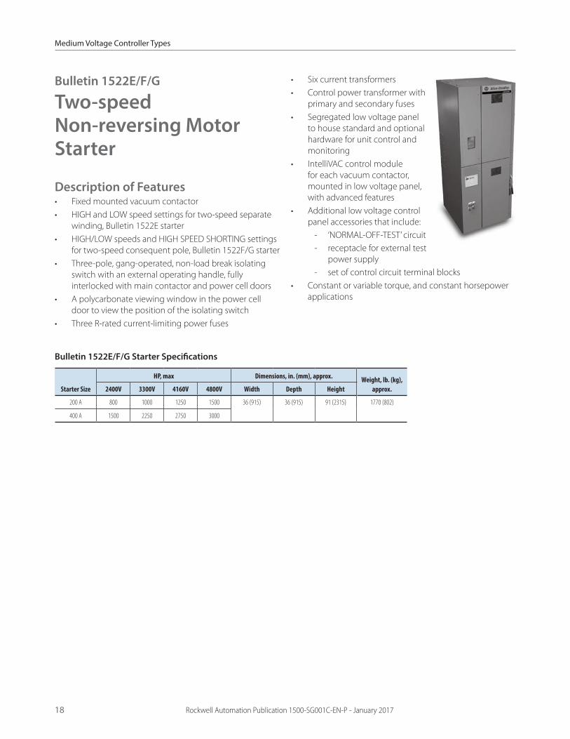
Bulletin 1522E/F/G
Two-speed Non-reversing Motor Starter
Description of Features• Fixed mounted vacuum contactor• HIGH and LOW speed settings for two-speed separate
winding, Bulletin 1522E starter • HIGH/LOW speeds and HIGH SPEED SHORTING settings
for two-speed consequent pole, Bulletin 1522F/G starter• Three-pole, gang-operated, non-load break isolating
switch with an external operating handle, fully interlocked with main contactor and power cell doors
• A polycarbonate viewing window in the power cell door to view the position of the isolating switch
• Three R-rated current-limiting power fuses
• Six current transformers• Control power transformer with
primary and secondary fuses• Segregated low voltage panel
to house standard and optional hardware for unit control and monitoring
• IntelliVAC control module for each vacuum contactor, mounted in low voltage panel, with advanced features
• Additional low voltage control panel accessories that include:
- ‘NORMAL-OFF-TEST’ circuit - receptacle for external test
power supply - set of control circuit terminal blocks
• Constant or variable torque, and constant horsepower applications
Bulletin 1522E/F/G Starter Specifications
Starter Size
HP, max Dimensions, in. (mm), approx. Weight, lb. (kg), approx.2400V 3300V 4160V 4800V Width Depth Height
200 A 800 1000 1250 1500 36 (915) 36 (915) 91 (2315) 1770 (802)
400 A 1500 2250 2750 3000

Medium Voltage Controller Types
Rockwell Automation Publication 1500-SG001C-EN-P - January 2017 19
Bulletin 1522E Power Circuit Schematic
L1 L2 L3 GND IS
F1
F1
F1
F2 F2
GFCT1(optional)
CPT1
CT1
CT2
CT3
T1
T2
T3
T11
T12
T13
S
S
S
FC
FC
FCBL
K W
GFCT2(optional) CT4
CT5
CT6BL
K W
M
Bulletin 1522F Power Circuit Schematic
L1 L2 L3 GND IS
F1
F1
F1
F2 F2
GFCT1(optional)
CPT1
CT1
CT2
CT3
T1
T2
T3
T11
T12
T13
S
S
S
FC1
FC1
FC1
BLK W
GFCT2(optional) CT4
CT5
CT6
BLK W
FC2
FC2
FC2
M

Medium Voltage Controller Types
20 Rockwell Automation Publication 1500-SG001C-EN-P - January 2017
Bulletin 1560E/1562E
SMC Flex™ Smart Electronic Soft Start Motor Controller
Description of FeaturesThe Bulletin 1562E is a flexible combination motor controller available in two main configurations:• A modified two-high cabinet (two complete controllers)• A combination of a one-high full voltage non-reversing
(FVNR) cabinet and a 1560E unit (one complete controller)
Based around the SMC Flex Smart motor control module, we offer a combination of controlling, electronic motor-starting styles:• Soft start with Selectable
Kickstart• Soft stop• Current limit start with
Selectable Kickstart• Linear Speed Acceleration(1) with
Selectable Kickstart• Linear speed deceleration(1)
• Dual ramp with Selectable Kickstart
• Full voltage• Preset slow speed
The SMC Flex also offers an optional pump control module to completely mitigate the damaging effects of water hammer within water and wastewater industry applications.
The Bulletin 1562E features both isolation and bypass vacuum contactors. The Bulletin 1560E is a retrofit controller specifically designed to smoothly integrate with an existing customer-supplied starter to enable all the combination controls listed in this section.
Bulletin 1560 E and Bulletin 1562E Controllers
Retrofit Controller Combination Controller

Medium Voltage Controller Types
Rockwell Automation Publication 1500-SG001C-EN-P - January 2017 21
Bulletin 1560E/1562E Starter Specifications
Bulletin Voltage Rating (A) HP, max
Dimensions, in. (mm), approx. Weight, lb. (kg), approx.Width Depth Height
1560E 2400 200 800 26 (660) 36 (914) 91 (2311) 800 (363)
400 1500
600 2750 44 (1118) 1300 (590)
3300 200 1000 26 (660) 800 (363)
400 2250
600 4000 44 (1118) 1300 (590)
4160 200 1250 26 (660) 800 (363)
400 2750
600 4500 44 (1118) 1300 (590)
6600 200 2250 36 (914) 1400 (636)
400 4500
600 7500 44 (1118) 1300 (590)
6900 200 2500 36 (914) 1220 (554)
400 5000
600 7500 44 (1118) 1300 (590)
1562E 2400 200 800 36 (914) 36 (914)(1) 91 (2311)(2) 1400 (636)(3)
400 1500
600 2750 80 (2032) 36 (914) 91 (2311) 2325 (1056)
3300 200 1000 36 (914) 36 (914)(1) 91 (2311)(2) 1400 (636)(3)
400 2250
600 4000 80 (2032) 36 (914) 91 (2311) 2325 (1056)
4160 200 1250 36 (914) 36 (914)(1) 91 (2311)(2) 1400 (636)(3)
400 2750
600 4500 80 (2032) 36 (914) 91 (2311) 2325 (1056)
6600 200 2250 36 (914) 36 (914) 1400 (636)(3)
400 4500
600 7500 80 (2032) 2700 (1227)
6900 200 2500 62 (1575) 36 (914)(1) 91 (2311)(2) 2325 (1056)(3)
400 5000
600 7500 100 (2540) 36 (914) 91 (2311) 4000 (1812)
(1) Depth is 46 in. (1168 mm) with ArcShield enclosure with plenum.(2) Height is 128.5 in. (3264 mm) with ArcShield enclosure with plenum.(3) Weight is different with ArcShield.

Medium Voltage Controller Types
22 Rockwell Automation Publication 1500-SG001C-EN-P - January 2017
Bulletin 1560E Power Circuit Schematic
GNDCT1
CT2
CT3
A OUT
B OUT
C OUT
A IN
B IN
B
C IN
M
Bulletin 1562E Power Circuit Schematic
CT1
CT2
CT3
A OUT
B OUT
C OUT
B
L1 L2 L3 GND IS
F1
F1
F1
F2 F2
CPT1
GFCT(optional)
M
BLK W
M

Medium Voltage Controller Types
Rockwell Automation Publication 1500-SG001C-EN-P - January 2017 23
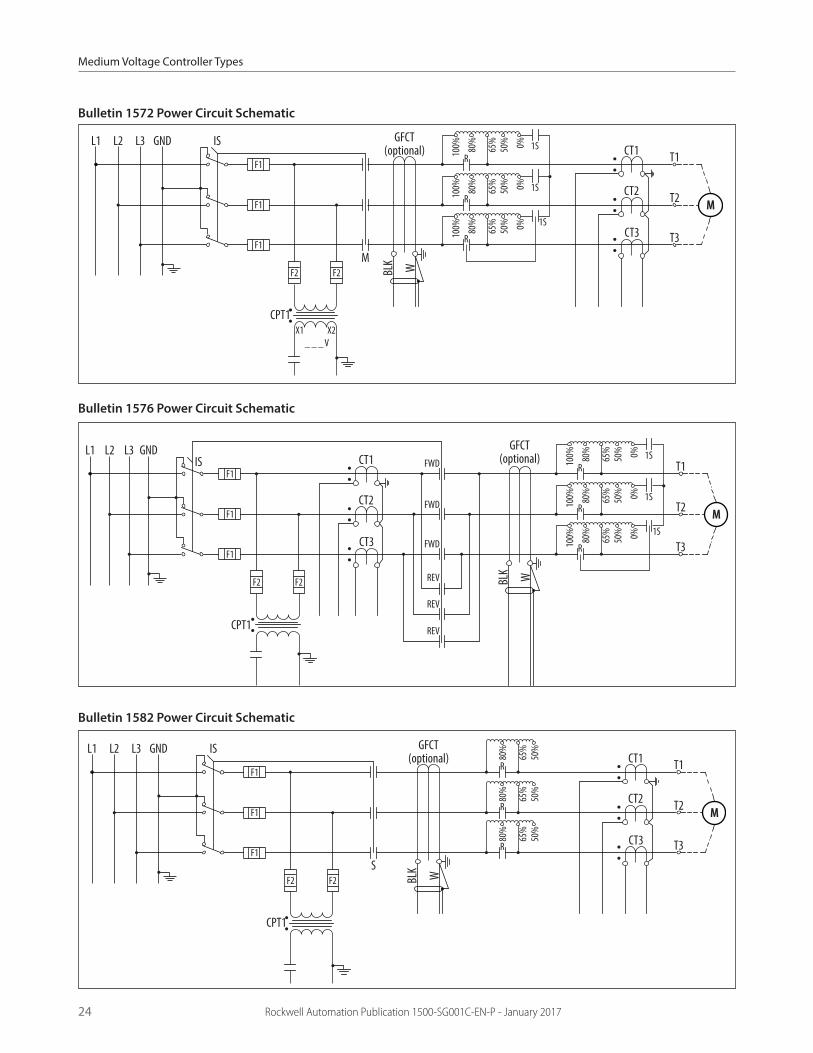
Bulletin 1572/1576/1582
Reduced Voltage Reversing and Non-reversing Autotransformer and Reactor Motor Starter
Description of Features• Fixed mounted vacuum contactors• (1S, 2S and RUN) contactors, with closed transition
operation, Bulletin 1572 non-reversing starter• (1S, FORWARD, REVERSE and RUN) contactors, with
closed transition operation, Bulletin 1576 reversing starter
• A three-pole, gang-operated, non-load break isolating switch with an external operating handle, fully interlocked with main contactor and power cell doors
• A polycarbonate viewing window in the power cell door to view the position of the isolating switch
• Three R-rated current-limiting power fuses• Three current transformers
• Control power transformer with primary and secondary fuses
• Segregated low voltage panel to house standard and optional hardware for unit control and monitoring
• IntelliVAC™ control module for each vacuum contactor, mounted in low voltage panel, with advanced features
• Additional low voltage control panel accessories that include:
- “NORMAL-OFF-TEST” circuit
- receptacle for external test power supply
- set of control circuit terminal blocks
• NEMA medium duty, dry type, three-winding autotransformer with 50, 65 and 80% taps. The 65% tap is used unless otherwise specified.
Bulletin 1572/1576/1582 Starter Specifications
Controller Type Starter Size
HP, max Dimensions, in. (mm), approx. Weight, lb. (kg), approx.2400V 3300V 4160V 4800V Width Depth Height
1572 200 A 800 1000 1250 1500 56 (1422) 36 (914) 91 (2311) 3750 (1703)
400 A 1500 2250 2750 3000
600 A 2250 4000 4500 5500 80 (2032) 5000 (2270)
800 A 3500 5000 6000 7000 100 (2540)
1576 200 A 800 1000 1250 1500 80 (2032) 3750 (1703)
400 A 1500 2250 2750 3000
800 A 3500 5000 6000 7000 100 (2540) 5000 (2270)
1582 200 A 800 1000 1250 1500 56 (1422) 3750 (1703)
400 A 1500 2250 2750 3000
600 A(1) 2250 4000 4500 5500 80 (2032) 5000 (2270)
800 A(1) 3500 5000 6000 7000 100 (2540)
(1) 600 A and 800 A controllers require a separately quoted autotransformer with minimum dimensions of 52 in. (1321 mm) wide, 46 in. (1168 mm) deep, and 66 in. (1676 mm) high.
Medium Voltage Controller Types
24 Rockwell Automation Publication 1500-SG001C-EN-P - January 2017
Bulletin 1572 Power Circuit Schematic
L1 L2 L3 GND IS
F1
100% 80
%
65%
50% 0%
F1
F1
F2 F2
GFCT(optional)
CPT1
_ _ _ V
CT1
CT2
CT3
T1
T2
T3
M
BLK W
100% 80
%
65%
50% 0%
100% 80
%
65%
50% 0%
R
R
R
1S
1S
1S
X2X1
M
Bulletin 1576 Power Circuit Schematic
L1 L2 L3 GNDIS
F1
100% 80
%
65%
50% 0%
F1
F1
F2 F2
GFCT(optional)
CPT1
CT1
CT2
CT3
T1
T2
T3FWD
REV
REV
REV
FWD
FWD
BLK W
100% 80
%
65%
50% 0%
100% 80
%
65%
50% 0%
R
R
R
1S
1S
1S
M
Bulletin 1582 Power Circuit Schematic
L1 L2 L3 GND IS
F1
80%
65%
50%
F1
F1
F2 F2
GFCT(optional)
CPT1
CT1
CT2
CT3
T1
T2
T3
S
BLK W
80%
65%
50%
80%
65%
50%
R
R
R
M

Medium Voltage Controller Types
Rockwell Automation Publication 1500-SG001C-EN-P - January 2017 25
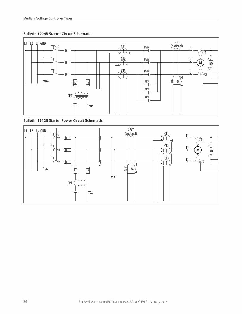
Bulletin 1906B/1912B
Full Voltage Reversing and Non-reversing Brush-type Synchronous Motor Starter
Description of Features• Bulletins 1906B and 1912B are designed as a complete
reversing and non-reversing synchronous starter, respectively(1)
• Available with or without static exciter• Features a control power transformer (CPT) with
primary and secondary fuses for converting line voltage to single phase 120 V for low voltage devices
• Forward-mounted vacuum contactors are implemented within the Bulletin 1906B starter
• The Bulletin 1912B starter showcases both forward and reverse vacuum contactors
• Standard SyncProII field application and protection system
(1) Refer to the standard features provided with the Bulletin 1506 and 1512 motor controllers.
Rockwell Automation Publication 1500-SG001C-EN-P - January 2017 25
Bulletin 1906B Starter Specifications
Starter Size
HP, max Dimensions, in. (mm), approx. (1) Weight, lb. (kg), approx.2400V 3300V 4160V 4800V Width Depth Height
200 A 800 1000 1250 1500 26 (660) 36 (914) 91 (2311) 1075 (490)
400 A 1500 2250 2750 3000
800 A 3500 5000 6000 7000 92 (2337) 3570 (1619)
(1) These dimensions do not include static exciter.
Bulletin 1912B Starter Specifications
Starter Size
HP, max Dimensions, in. (mm), approx. (1) Weight, lb. (kg), approx.2400V 3300V 4160V 4800V 6600V 6900V Width Depth Height
200 A 800 1000 1250 1500 2000 2250 26 (660) 36 (914) 91 (2311) 1075 (490)
400 A 1500 2250 2750 3000 4500
450 A 1750 2500 3000 3500 Contact factory
600 A 2750 3500 4500 5500 36 (914) 1700 (773)
800 A 3500 5000 6000 7000 56 (1422) 1950 (885)
(1) These dimensions do not include static exciter.
Medium Voltage Controller Types
26 Rockwell Automation Publication 1500-SG001C-EN-P - January 2017
Bulletin 1906B Starter Circuit Schematic
L1 L2 L3 GNDIS
F1
F1
F1
F2 F2
GFCT(optional)
CPT1
CT1
CT2
CT3
T1
T2
T3FWD
REV
REV
REV
FWD
FWD
BLK W
F1
F2
R2
R1
(+)
(–)
M RD
Bulletin 1912B Starter Power Circuit Schematic
L1 L2 L3 GNDIS
F1
F1
F1
F2 F2
GFCT(optional)
CPT1
CT1
CT2
CT3
T1
T2
T3M
BLK W
F1
F2
R2
R1
(+)
(–)
M RD

Medium Voltage Controller Types
Rockwell Automation Publication 1500-SG001C-EN-P - January 2017 27
Bulletin 1906L/1912L
Full Voltage Reversing and Non-reversing Brushless Synchronous Motor Starter
Description of Features• Bulletins 1906L and 1912L are designed as complete
reversing and non-reversing synchronous starters, respectively(1)
• Available with or without static exciter
• Features a control power transformer (CPT) with primary and secondary fuses for converting line voltage to single phase 120 V for low voltage devices
• Forward-mounted vacuum contactors are implemented within the Bulletin 1906B starter
• The Bulletin 1912L starter showcases both forward and reverse vacuum contactors
(1) Refer to the standard features provided with the Bulletin 1506 and 1512 motor controllers.
Bulletin 1906L Starter Specifications
Starter Size
HP, max Dimensions, in. (mm), approx. (1) Weight, lb. (kg), approx.2400V 3300V 4160V 4800V Width Depth Height
200 A 800 1000 1250 1500 54 (1372) 36 (914) 91 (2311) 2370 (1076)
400 A 1500 2250 2750 3000
800 A 3500 5000 6000 7000 74 (1880) 2400 (1090)
(1) These dimensions do not include static exciter.
Bulletin 1912L Starter Specifications
Starter Size
HP, max Dimensions, in. (mm), approx. (1) Weight, lb. (kg), approx.2400V 3300V 4160V 4800V 6600V 6900V Width Depth Height
200 A 800 1000 1250 1500 Contact factory 26 (660) 36 (914) 91 (2311) 1075 (490)
400 A 1500 2250 2750 3000
450 A 1750 2500 3000 3500
600 A 2750 3500 4500 5500 54 (1372) 1950 (885)
800 A 3500 5000 6000 7000 74 (1880) 2400 (1090)
(1) These dimensions do not include static exciter.

Medium Voltage Controller Types
28 Rockwell Automation Publication 1500-SG001C-EN-P - January 2017
Bulletin 1906L Starter Power Circuit Schematic
L1 L2 L3 GNDIS
F1
F1
F1
F2 F2
GFCT(optional)
CPT1
CT1
CT2
CT3
T1
T2
T3
BLK WF4
CPT2
M
FWD
REV
REV
REV
FWD
FWD
Bulletin 1912L Starter Power Circuit Schematic
L1 L2 L3 GNDIS
F1
F1
F1
F2 F2
GFCT(optional)
CPT1
CT1
CT2
CT3
T1
T2
T3M
BLK WF4
CPT2
M

Incoming Line Units
Rockwell Automation Publication 1500-SG001C-EN-P - January 2017 29
Bulletin 1591A/B
Incoming Line Units
Description of Features• Incoming bus arrangement for top or bottom cables• Provision for the low voltage panel and door• Metering CTs and PTs available• Lug pad with provision for multiple incoming cable lug
terminations• Only Bulletin 1591B comes as a two-high structure; also
available in ArcShield designs 1591A 1591B
Bulletin 1591A/B Incoming Line Units Specifications
Voltage Rating
Incomer Size, in. (mm)
Dimensions, in. (mm), approx. Weight, lb. (kg), approx.Width Depth Height
2400/3300 18 (457) 18 (457) 36 (914) 91 (2311)(2)(4) 600 (272)(3)
4160/4800 36 (914) 36 (914) 91 (2311)(2) 800 (363)(3)
6600/6900 44 (1118)(1) 44 (1118) 91 (2311) 1200 (545)
(1) A 44-inch incomer is only available when a 3000 A power bus is used.(2) Height is 128.5 inches 3264mm) with ArcShield enclosure with plenum.(3) Weight is different with ArcShield.(4) Only available size for 1591B.
Bulletin 1591A/B Power Circuit Schematic
1L3
1L2Customer’sIncoming
Line
L1 L2 L3 GRD
1L1

Incoming Line Units
30 Rockwell Automation Publication 1500-SG001C-EN-P - January 2017
Bulletin 1592BF, 1592F/M, and 1594F/M
Fused and Non-fused Load-break Switches
Description of Features• Main load break switch for switching primary power
source• Feeder load break switch for switching other loads• Isolation between upper and lower power cells• The operating handle is fully interlocked with the power
cell door• Provisions on the operating handle for key interlocking• A polycarbonate viewing window in the power cell
door to view the position of the isolation handle
• Protective guard over the line terminals, inside the power cell, to barrier off medium voltage when the power door is open
• Feeders for two-high structures
• Bulletin 1592BF – fused load break switch, designed as a feeder for two-high structures
• Bulletin 1592F/M – fused load break switch, fused feeder, and mains
• Bulletin 1594F/M – non-fused load break switch, designed for feeder and mains
Bulletin 1592BF Switch Specifications(1)
Starter Size
Transformer Size (kVA) Dimensions, in. (mm), approx. Weight, lb. (kg), approx.2400V 3300V 4160V 4800V 6600V 6900V Width Depth Height
200 A 700 1000 1250 2000 36 (914) 91 (2311) 1770 (804)(2)
400 A 1500 2000 2500 2750 N/A 1770 (804)
(1) One 1592BF occupies half of a two-high structure.(2) Includes complete two-high structure weight with two 1592BF units.(3) Weight is different with ArcShield.
Bulletins 1592F/M and 1594F/M Switch Specifications
Switch Size
Switch Size, max Dimensions, in. (mm), approx. Weight, lb. (kg), approx.2400V 3300V 4160V 4800V 6600V 6900V Width Depth Height
600 A (1) 36 (914)(2) 36 (914) 91 (2311) 1770 (804)
1200 A (1) N/A 54 (1372)(3) 42 (1067) 2500 (1135)
(1) Available in all sizes except 1200 A at 6600 and 6900 V.(2) If an isolated, low-voltage panel is required, the width increases by 18 inches (272 mm) and weight increases accordingly.(3) If an isolated, low-voltage panel is required or incoming cables are fed from the bottom, the width increases by 18 inches (272 mm) and the weight increases accordingly. If the 42-inch deep unit is positioned on
either end of 36-inch (94 mm) deep structures, the width increases by an additional 4 inches (104 mm).

Incoming Line Units
Rockwell Automation Publication 1500-SG001C-EN-P - January 2017 31
Bulletin 1592BF/1592F Power Circuit Schematic
L1 L2 L3 GRD LBS
F1
F1
F1
H1
MediumVoltage
Load
H2
H3
Bulletin 1592M Power Circuit Schematic
1L3
1L2Customer’sIncoming
Line
L1 L2 L3 GRD
1L1LBS
F1
F1
F1
Bulletins 1592F and 1594F Power Circuit Schematics
L1 L2 L3 GRD LBSH1
MediumVoltage
Load
H2
H3
Bulletins 1592M and 1594M Power Circuit Schematics
1L3
1L2Customer’sIncoming
Line
L1 L2 L3 GRD
1L1LBS

Publication 1500-SG001C-EN-P - January 2017Supersedes 1500-SG001B-EN-P - March 2011 Copyright © 2017 Rockwell Automation, Inc. All rights reserved. Printed in the U.S.A.
Power, Control and Information Solutions HeadquartersAmericas: Rockwell Automation, 1201 South Second Street, Milwaukee, WI 53204-2496 USA, Tel: (1) 414.382.2000, Fax: (1) 414.382.4444Europe/Middle East/Africa: Rockwell Automation NV, Pegasus Park, De Kleetlaan 12a, 1831 Diegem, Belgium, Tel: (32) 2 663 0600, Fax: (32) 2 663 0640Asia Paci�c: Rockwell Automation, Level 14, Core F, Cyberport 3, 100 Cyberport Road, Hong Kong, Tel: (852) 2887 4788, Fax: (852) 2508 1846
www.rockwel lautomation.com
Allen-Bradley, LISTEN. THINK. SOLVE., ArcShield, CENTERLINE, E300, IntelliCENTER, IntelliVAC, and Rockwell Automation are trademarks of Rockwell Automation, Inc. Trademarks not belonging to Rockwell Automation are property of their respective companies.
Maximize Your Automation Investment
Rockwell Automation Services & SupportGlobal Support. Local Address. Peace of Mind.Providing the resources you need, when and where you need them, Rockwell Automation has an integrated, global network of ISO-certified repair centers, exchange hubs, field service professionals, IACET-recognized training centers, certified technical phone support centers and online tools.
www.rockwellautomation.com/go/services
Visit the Rockwell Automation Support Center at www.rockwellautomation.com/knowledgebase for technical information and assistance, plus:
• View technical/application notes • Subscribe for product/service email notifications
• Obtain software patches • Submit a Question, Live Chat, Support Forums and more
Visit Get Support Now at www.rockwellautomation.com/go/support to select your country and find your local support information.
MRO Demand Management
• Comprehensive asset management planning
• Reliability services
• Warranty tracking
• Quick access to global spare parts inventory
Lifecycle Extension & Migrations
• Installed Base Evaluation™
• Pinpoint obsolescence risk
• Tools and lifecycle support service agreements to mitigate production risk
Network & Security Services
• Control system lifecycle services
• Manage network convergence
• Security technology, policies and procedures services
Safety Services
• Safety assessments and remediation
• Safety design, integration and validation services
Meet Your Everyday Technical NeedsRemote Support & Monitoring
• Real-time product, system and application-level support
• Unlimited online resources and tools
• Live chat and support forums
• Secure equipment monitoring, alarming and diagnostics
Training Services
• Instructor-led and computer or web-based courses
• Virtual classroom
• Training assessments
• Workstations and job aids
OnSite Services
• Embedded engineering
• Preventive maintenance
• Migrations and conversions
• Start-up and commissioning
Repair Services
• Product remanufacturing
• Repair services on a full range of industrial automation brands and products
• Annual repair agreements


