12
MEDIUM VOLTAGE SOFT STARTER TYPE VFS UP TO 5 MW UP TO 12 kV UP TO 400 A

MEDIUM VOLTAGE SOFT STARTER TYPE VFS
UP TO 5 MW
UP TO 12 kV
UP TO 400 A

MOcOTech PresenTs The VAriAble Fre-qUency sOFT sTArTer (VFs) WiTh MAny UniqUe FeATUres And AdVAnTAges.
2
cUsTOMer AdVAnTAges· Reduction of service and maintenance costs for drives
· Increase of lifetime for drives
· Start / stop with low mechanical stress
· Reduction of starting current
· Minimum voltage drop in the power supply
· Increasing the break away torque of the motors to be started due to frequency reduction
· Cost saving compact modular design with many options
· Basic design including mains connection, power electronics, pt, ct and control
· Withdrawable power module with mains contactor, by pass contactor and power electronics
· HH fuses for reduction of short circuit capacity
· All components with full options in one cabinet only
· Indoor installation
· Operation and maintenance of VFS from the front
· VFS may be mounted with backside against a wall
· Single or lined up installation
· Cost reduction for lined up installation with common bus bar
· Bus bar extendable
· Only 1 square meter floor space for each VFS
· Small incoming cable connection panel (ICCP)
· MV part metal enclosed
· Control part metal clad
· Cable connection from the bottom
· Removable cable entry plates ease the connection
· Service continuity category LSC 2A class PI
· Each thyristor protected with BOD against transient overvoltage

3
MEDIUM VOLTAGE SOFT STARTER TYPE VFS
inTernAl Arc APPrOVed
T yPe APPrOVed
highesT OPerATOr sAFeT y
highesT AVAilAbiliT y
highesT OPerATiOn sTAbiliT y
drAW OUT POWer MOdUle
UlTiMATe breAk AWAy TOrqUe
4
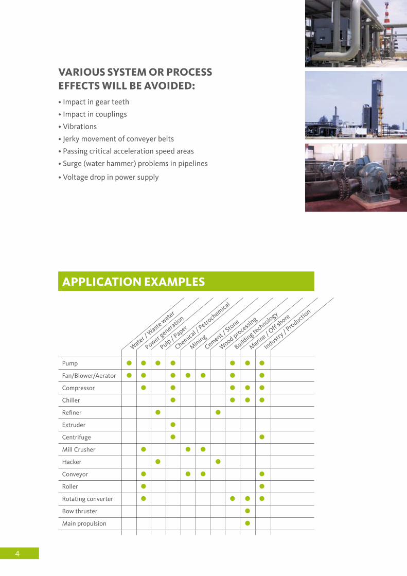
VAriOUs sysTeM Or PrOcess eFFecTs Will be AVOided:• Impact in gear teeth
• Impact in couplings
• Vibrations
• Jerky movement of conveyer belts
• Passing critical acceleration speed areas
• Surge (water hammer) problems in pipelines
• Voltage drop in power supply
Pump
Fan/Blower/Aerator
Compressor
Chiller
Refiner
Extruder
Centrifuge
Mill Crusher
Hacker
Conveyor
Roller
Rotating converter
Bow thruster
Main propulsion
Water / W
aste w
ater
Power generatio
n
Pulp / Paper
Chemical / Petro
chemical
Mining
Cement / Stone
Wood processing
Building te
chnology
Marine / O
ff shore
Industry / P
roduction
APPlicATiOn exAMPles

5
OPerATOr sAFeTy· Internal arc withstand tested acc to IEC 62271 part 200
· Type tested and approved design
· Operation of all components from front with closed doors
· No load switch (NLS) between bus bar and VFS equipment
· Isolating plate between open NLS contacts and bus bar provides a clear visible isolating distance between bus bar and service parts in VFS components
· Earthing switch
· Mechanical interlock between NLS, earthing switch and front door
· Common earthing bus bar
· Cylindrical door lock
· Electrical isolation between LV and MV circuits by use of fibre optic cable
FUncTiOns· Soft start
· Soft stop
· Frequency soft start for increase of break away torque
· Active break stop for quick stand still of motor
· DOL start
· Direct stop
· Motor turn function for machines with a long stand by time
· Starting curves: torque / time or current / time freely selectable
· Different starting ramps for pump control
· Dual start adjustment
· Integrated full motor protection features
· Alternative use of standard protection relais possible
· Test with small LV motor
xx
xx
Reduced frequency soft start with sinus wave skip function provides ultimate breakaway torque with low starting current
(principle diagram)

To avoid voltage drop in the power supply,
the starting current can be adjusted to a
pre-set limit. The first chart shows the
starting current. Black graph for DOL
start, coloured graphs for different pre set
maximum currents. The second graph
shows the corresponding torque
characteristics. Extra breakaway torque is
available due to frequency modulation in
the first starting phase. Raised current
limitation results into additional decreased
voltage drop.
sTArT cUrrenT liMiTATiOn (Adjustable max. current)
The high breakdown torque when starting
a motor DOL (black graph in first chart) can
be avoided.
Therefore a maximum torque during
acceleration is pre-selected (coloured graphs
in first chart). This reduces stress and impact
on the rotating equipment:
motor, coupling, gearbox, driven machine,
etc. Lifetime of machinery increases,
damages are avoided.
A pre-selection of the required starting time
is also possible (second chart).
sOFT sTArT (Adjustable max. torque)
AdjUsTAble sTArT TiMe
Special acceleration and run down ramps
can be provided for different applications.
For example centrifugal pump control:
Controlled start up avoids damages in pipe
systems due to torque peaks and sudden
pressure increase.
To avoid water hammer effect during pump
stop the run down is controlled in order to
reach a smooth flow reduction. This avoids
excessive noise and damage in the pipe
system (black graphs in the charts for
DOL start and coloured graphs for controlled
pump start / stop). A pre-selection of the
required run down time is also possible.
sPeciAl rAMPs
Example centrifugal pump start and stop
6
cU
rr
en
T
sPeed
TO
rq
Ue
sPeed
TO
rq
Ue
sPeed
sPe
ed
sTArTing TiMe
FlO
Wr
AT
e
sTArTing TiMe
FlO
Wr
AT
e
sTOP TiMe

7
OPTiOns· MV cable connection from top
· Incoming cable section right- or backsided
· Customised MV panels attached to same bus bar
· Different stage of completion for MV components inside VFS panel. (see single line diagram page 10)
· Different fixed power factor correction solutions
· Arc pressure release duct
· Remote I/O field housing
· Profibus and Modbus interface
· Many more options. Please consult us with your demands
sTAndArds· IEC 62271 Part 1 · IEC 62271 Part 102
· IEC 62271 Part 200 · IEC 60470 Part 2000
· IAC AFL 31,5 kA / 1 sec
· Ship classification approval (1)
TechnicAl dATA
Rated voltage kV 7,2 12
Rated current bus bar A …1850 …1850
Rated current feeder A …400(2) …400(2)
Rated short time current kA …40 …40
Rated peak withstand current kA …100 …100
Rated power frequency withstand voltage kV 20 28
Rated lightning withstand voltage kV 60 75
Operating frequency Hz 45–65
Protection class IP IP IP4X(2)
Site altitude m …1000(2)
diMensiOns And WeighTs
Rated voltage kV 7,2 12
Height mm 2250 2550
Depth mm 1100 1100
VFS (soft starter panel) width mm 900 900
ICCP (incoming cable connection panel) width mm 350 350
ICCP weight kg ...400 ...400
VFS weight kg ...1500 ...1500
Explanations: (1) project related / option; (2)higher / more on request
Please ask for our general technical specification (GTS) containing more details.

8
keybOArd
· High quality and low cost when integrating the VFS into your drive systems.
· Digital microprocessor control with non–volatile memory and real time clock
· Multi level password access for operation and parameter adjustment
· Large illuminated interactive multi language display with 6 lines
· Metering and indication functions
· 10 LED for status information
· 4 LED for variable use
· Error memory, statistical data and diagnostic functions
· Standard CAN interface
reMOTe i/OConnection of 8 or 12 REMOTE RTD sensors and up to
12 digital in- and 12 digital output signals to be used for
local control functions at a remote IP 54 connection box
installed beside the drive saving a lot of cabling work.RTD PCB1 Left bearing (Machine)
2 Right bearing (Machine)
3 Front bearing (Motor)
4 Motor winding A1
5 Motor winding B1
6 Motor winding C1
7 Back bearing (Motor)
8 Spare
RTD 9-12 Spare
DI+DO 1-12 for local Signals
Can Bus
CPU
RUN
READY
FAULT
LOCAL
REMOTE
RUN
STOP
DOL
TEST
AUX_A
AUX_B
AUX_C
AUX_D
MOTOR TURN
SOFT STOP
STOP
SET
MENU/OK
LAMP TEST
HORN OFF RESET

MiMic diAgrAM WiTh led POsiTiOn indicATOrs
A mimic diagram with position
indicators provides clear status
information about the main circuit
to the operator. All position indica-
tors including the SCR symbols are
LED illuminated.
The LED alternate between red /
green and grey colour for the
various status conditions.
9
m

single line
10
· Lined up VFS starter with common main bus bar
· Individual VFS starter for each motor
· Space saving due to small dimensions
· Low price
· Standard panels can be attached
· High availability
Incoming panel ICCP (o)
VFS panel
Bus bar
ON – OFF no load switch (o)
Earthing switch (o)
Current limiting HH fuses (o)
Earthing bolt
Surge arrestors (o)
Measuring voltage transformer
Measuring current transformer
Mains contactor (o)
By-pass contactor
SCR power stack
Insulation plate (o)can be inserted from front
1
2
3
4
5
6
7
8
9
10
11
12
13
14
This single line is only symbolic and might not be in line with point of installation for hardware components
(o) = optionPls consult us if you require other options
insTAllATiOn AlTernATiVe A
M3 ~
M3 ~
M3 ~
M3 ~
M 1 M 2 M 3 M 4IN
1 2
9
11
12
13
3 ~
3
6
4
5
8
14
10
7

· Lined up VFS starter with common main- and aux starting bus bar
· Several motors share one VFS starter
· Individual motor will be switched to main bus bar after start up
· Space saving due to small dimensions
· Low price
11
· Stand alone VFS starter
· Individual VFS Starter for each motor
· Clear motor - starter allocation
· High availability
insTAllATiOn AlTernATiVe b
insTAllATiOn AlTernATiVe c
IN M 1 M 2
M3 ~
M3 ~
M 3 M 4
M3 ~
M3 ~
M3 ~
M3 ~
M3 ~
VFS 1 M 1 M 2 M 3IN

mocotech gmbh Nordring 20 47495 Rheinberg – Germany phone +49 (0)2843 90488-0 fax +49 (0)2843 90488-44 [email protected] www.mocotech.de
PrOFile
The first choice for your motor starters should be a company which concentrates on your specific project
requirements, supports you and takes full responsibility for the design and production of your starters.
Mocotech realises tailor made solutions based on well proven technologies. We combine flexible solutions
and high quality to implement your individual project goals. Our full attention is on your selected targets
and demands. 60 years experiance in drive technology ensure and guarantee the service availability and
operation stability of your plants.
PrOdUcT
Mocotech presents with the VFS starter many unique technical features. Mocotech is the
first company at the global market which has obtained the IEC 62271-200 type test to meet current
safety demands for MV switchgears and motor starters. You receive at MOCOTECH the highest
value for your drive technology investment.
serVice
Qualified and experienced engineers, take every day the full responsibility for the design, engineering,
production and quality control. We provide after sales services for and training of our customers in our
headquarters at Rheinberg in Germany. Local dealers and agents are available for site support in most areas
around the world.
cOMMiTMenT
We are pleased to serve the steady increasing number of frequent customers who put their trust in our
company. We commit ourselves to produce only reliable and competitive motor starters in top quality. You
can always expect the best from Mocotech.
080
1


