POINT-OF-CARE UNIT 8000 SERIES SILENCE OPTIONS 1 4 7 CLEAR 2 5 8 0 3 6 9 . ENTER CANCEL SYSTEM ON Directions for Use Point-of-Care Unit, 8000 Series ALARIS Medical Systems, Inc. Medley ™ Medication Safety System
Transcript
POINT-OF-CARE UNIT8000 SERIES
SIL
EN
CE
OP
TIO
NS
147
CLE
AR
2580
369.
EN
TE
R
CA
NC
EL
SY
ST
EM
ON
Directions for U
seP
oint-of-Care U
nit, 8000 Series
ALA
RIS
Medical S
ystems, Inc.
Medley
™M
edication Safety S
ystem
GENERAL CONTACT INFORMATION
Customer Advocacy - North AmericaClinical and technical feedback.
Technical Support - North AmericaMaintenance and service information support; troubleshooting.
United States:Phone:
(858) 458-6003(800) 854-7128, Ext. 6003
Canada:Phone:
Eastern: (800) 908-9918Western: (800) 908-9919
Customer Care - North AmericaInstrument return, service assistance, and order placement.
United States:Phone:
(800) 482-4822
Canada:Phone:
(800) 387-8309
SPECIAL PRODUCT NOTEThis document and some display screens make reference toa module that is not currently available, the Medley™ EtCO2Module. At the time of this publication, the Medley™ EtCO2Module has not been released for commercial sale and ALARISMedical Systems, Inc. may never make the EtCO2 Moduleavailable for commercial sale.
The Medley™ Medication Safety System is a modular infusionand monitoring system intended for use in today’s growingprofessional healthcare environment, for use in adult, pediatricand neonatal care. It consists of the Point-of-Care Unit (8000Series), the Guardrails® Safety Software, and up to4 detachable modules (or “channels”) which provide infusionor monitoring capabilities.
NOTE: The Medley™ Point-of-Care Unit was formerly known asthe Medley™ Programming Module.
The Medley™ Point-of-Care Unit is the core of the Medley™
System and provides a common user interface forprogramming infusions and monitoring, which helps to reducecomplexity at the point of care.
Guardrails® Safety Software for the Medley™ System brings anew level of medication error prevention to the point of patientcare. The Guardrails® Safety Software features medicationdosing and concentration guidelines for up to 10 patient-specific care areas, referred to as profiles. Each profilecontains a specific drug library and channel labels, as well asinstrument configurations appropriate for the care area.Optional drug-specific Guardrails® Clinical Advisories providevisual messages. Dosing limits for each drug entry may beeither Guardrails® Hard Limits that cannot be overriddenduring infusion programming or Guardrails® Soft Limits thatcan be overridden, based on clinical requirements.Concentration limits can only be Guardrails® Soft Limits.
A data set is developed and approved by the facility’s ownmulti-disciplinary team using the Guardrails® Editor, thePC–based authoring tool. A data set is then transferred to theMedley™ System by qualified personnel. The approved datasets are maintained by the Guardrails® Editor for futureupdates and reference.
Information about Guardrails® Alerts that occur during use isstored within the Medley™ Point-of-Care Unit, and can beaccessed using the Guardrails® Continuous QualityImprovement (CQI) Standard Software.
About the System
INTR
OD
UC
TION
INTRODUCTION 1Point-of-Care Unit, 8000 SeriesDirections for Use
Compliance with Federal Aviation Regulations: TheMedley™ Point-of-Care Unit has received a Statement ofCompliance with Federal Aviation Regulations for use as a“Portable Electronic Device Aboard Aircraft”. This is pursuantto the FAA Advisory Circular No. 91-21-1A and attested by anFAA Designated Engineering Representative with an FAA form8110-3, “Statement of compliance with the Federal AviationRegulations”.
Contraindications: None known.
This document provides directions for use for the Medley™
Point-of-Care Unit. For additional operating instructions,reference the Directions for Use (DFU) for the individualMedley™ Module(s).
2 INTRODUCTION Point-of-Care Unit, 8000 SeriesDirections for Use
Reference the “Alarms, Errors, Messages” chapter of this DFU for the definitions of various alerts.Reference the DFU that applies to the attached Medley™ Module(s) for features and definitions specificto that module.
Anesthesia Mode Allows anesthesiologist to access additional drugs, in each profile,that are appropriate to anesthesiology. It also features permanentpause. Clinical Advisories will not be displayed in this mode.
Battery Run Time Display Appears on Main Display prompt bar when Point-of-Care Unit isdisconnected from AC. If enabled, this feature provides a visualdisplay of estimated remaining battery run time under currentoperating conditions, when operating on battery.
Concentration Limits Limits specified for the range of concentrations allowed for aparticular drug in a profile.
Data Set Created using Guardrails® Editor authoring tool and then transferredto Point-of-Care Unit. A data set reflects facility’s best-practiceguidelines for IV drug administration and includes: Profile DrugLibraries, Clinical Advisories, instrument configurations, and ChannelLabel Libraries.
Features and Definitions
About the System (Continued)
Read all instructions before usingthe Medley™ System.
WARNING
INTR
OD
UC
TION
INTRODUCTION 3Point-of-Care Unit, 8000 SeriesDirections for Use
Features and Definitions (Continued)
Dose Checking Always Dose Checking option causes a Guardrails® Soft Alert tooccur each time a dose limit is exceeded. Drug label in MessageDisplay provides an indicator (“---” or “LLL”) that infusion is beyondcurrent Guardrails® Soft Limit.
Smart Dose Checking option causes an initial Guardrails® Soft Alertto occur when a dose limit is exceeded. Subsequent programmingbeyond dose limit will not receive an alert. Drug label in MessageDisplay provides an indicator (“---” or “LLL”) if infusion is beyondcurrent Guardrails® Soft Limit.
Guardrails® Safety Software Designed to help prevent programming errors by:
• Customizing device configurable settings to meet need ofselected hospital/facility area/unit (profile).
• Comparing user programming with hospital-defined best-practiceguidelines.
• Providing a Guardrails® Prompt if an out-of-limits entry is made.
Patient ID Entry An optional alphanumeric 16-character patient identifier can beentered and displayed.
• When enabled, ID entry defaults to Startup screen.• When disabled, ID entry is only accessible from System Options
screen.
Profile A unique set of system configuration settings and best-practiceguidelines for a specific patient population or patient type, andconsists of following 3 components:
• Instrument configuration settings.• A Guardrails® Drug Library, which includes drug names, standard
concentrations, dosing units, Guardrails® Limits, and optionalassociated Clinical Advisories for both continuous and bolus doseinfusion.
• A Channel Label Library with text (alphanumeric) labels, thatallows identification of modules that are actively infusing nondrugtherapies (for example, saline or TPN). Channel labels can alsobe used to identify route of delivery (for example, epidural).
Profile settings are established by the facility’s own multi-disciplinaryteam prior to system implementation. Profile parameters are used tocreate a data set, which is then transferred to the Point-of-Care Unit.
System Configuration Allow system settings to be customized. If Profiles feature isenabled, system settings defined for selected profile areautomatically activated.
Tamper Resist Provides a quick one-touch lockout of front panel keypad.
Alarm silence (pauses audio alarm for 120 seconds).
Alternating Current: Indicates device should be attached to alternating current source,50/60 Hz only.
Attention: Refer to accompanying documentation.
Canadian and U.S. Certification Mark: Products bearing this mark have been tested andcertified in accordance with applicable U.S. and Canadian electrical safety and performancestandards (CSA C22.2 No. 601.1, UL 2601-1 and IEC 60601–2–24).
Type CF defibrillation-proof equipment.
Communications connector for RS-232 attachment.
Electrostatic discharge (ESD).
Fuse Replacement: Replace fuse only with same type and rating.
Protection against fluid ingress: Drip Proof
IUI Connector: Inter-Unit Interface connector used to establish power and communicationsbetween Point-of-Care Unit and attached modules.
Main Power: Connected to alternating current, 100-240 VAC.
Manufacturing Date: Number adjacent to symbol indicates month and year of manufacture.
Potential Equalization Conductor (if so equipped). Note: If integrity of PEC or Hospital EarthSystem is in question, operate instrument using internal battery power.
Radio frequency (RF) radiation.
CAUTION: Federal (U.S.A.) law restricts this device to sale by or on order of a physician.
“SYSTEM ON”
Tamper Resist activate/deactivate switch.
4 INTRODUCTION Point-of-Care Unit, 8000 SeriesDirections for Use
Symbols
� ��
IPX1
!
nlyO
MM-YYYY
GETTING STARTED
GETTIN
G STA
RTED
GETTING STARTED 5
Warnings and Cautions
• When properly secured/snapped, the bottom latchprovides a very secure connection between modules. Ifnot properly latched, a module can be dislodged duringoperation.
• Do not use the Medley™ System near Magnetic ResonanceImaging (MRI).
• Disconnect from main (AC) and battery power whenperforming maintenance.
• Electrical shock hazard. Do not open case. Refer toqualified service personnel.
• Use of accessories or cables other than those specifiedmay result in degraded electromagnetic compatibilityperformance of this instrument.
WARNINGS
nlyO
Point-of-Care Unit, 8000 SeriesDirections for Use
Warnings and Cautions are provided throughout thisDirections for Use (DFU) to provide information needed tosafely and effectively use the Medley™ Medication SafetySystem and its accessories. Module-specific Warnings andCautions are covered in the applicable module’s DFU.
A is an alert to an imminent hazard whichcould result in serious personal injury and/or product damageif proper procedures are not followed.
A is an alert to a potential hazard which couldresult in serious personal injury and/or product damage ifproper procedures are not followed.
A is an alert to a potential hazard which couldresult in minor personal injury and/or product damage if properprocedures are not followed.
CAUTION
WARNING
DANGER
Explosion risk if used in the presence of flammable anesthetics.DANGER
6 GETTING STARTED Point-of-Care Unit, 8000 SeriesDirections for Use
Warnings and Cautions (Continued)
• The Medley™ System is not intended to replacesupervision by medical personnel. The user mustbecome thoroughly familiar with the Medley™ Systemfeatures, operation and accessories prior to use.
• Always use a grounded, three-wire receptacle. Wherethe integrity of the protective earth grounding system is indoubt, operate on internal battery.
• Should an instrument be dropped or severely jarred, itshould be immediately taken out of use and inspected byqualified service personnel, to ensure its proper functionprior to reuse.
• If an instrument appears damaged, contact ALARISMedical Systems for authorization to return it for repair.
CAUTIONS
SYSTEM
ON
Operating Features, Controls and Indicators
Front/Side View
IUI Connector, Left(not visible)
Main Display
Soft Keys: When pressed,allows selection of options orinfusion parameters appearingon Main Display adjacent tosoft key.
Silence Key: When pressedduring an alarm, silences audiofor 2 minutes.
Options Key: Whenpressed, allows access toavailable System or ChannelOptions.
Up/Down Arrows: Whenpressed, increases or decreasesparameter with each key press orscrolls up and down whenpressed and held.
Enter Key: When pressed,confirms current parameter entry.
Cancel Key: When pressed,sequentially backs out of currentsetup sequence.
Decimal Key: When pressed,inserts a decimal point in numericdata.
Numeric Keypad
GETTIN
G STA
RTED
GETTING STARTED 7Point-of-Care Unit, 8000 SeriesDirections for Use
8 GETTING STARTED Point-of-Care Unit, 8000 SeriesDirections for Use
Operating Features, Controls and Indicators (Continued)
Rear View
IUI Connector, Right IUI Connector, Left
Primary Audio Speaker
Connector Plug over RJ45Communication Data Port
Tamper Resist Switch
Power Cord Strap
Option Upgrade Panel
Use this bolt to reorientPole Clamp 90° forattachment to a bed railinstead of a pole.
GETTIN
G STA
RTED
GETTING STARTED 9Point-of-Care Unit, 8000 SeriesDirections for Use
Installation
Instruments are tested and calibrated before they arepackaged for shipment. To ensure proper operation aftershipment, it is recommended that an incoming inspection beperformed before placing the instrument in use.
Prior to placing the Medley™ System in use:
1. Perform check-in procedure per Medley™ MaintenanceSoftware/User Manual (Model 8970C, or later).
2. Verify whether or not Profiles feature has been enabled.Reference “Reviewing System Configuration” section in“Getting Started” chapter.
NOTE: To enable the Profiles feature, a hospital-definedbest-practice data set must be uploaded to the Point-of-CareUnit.
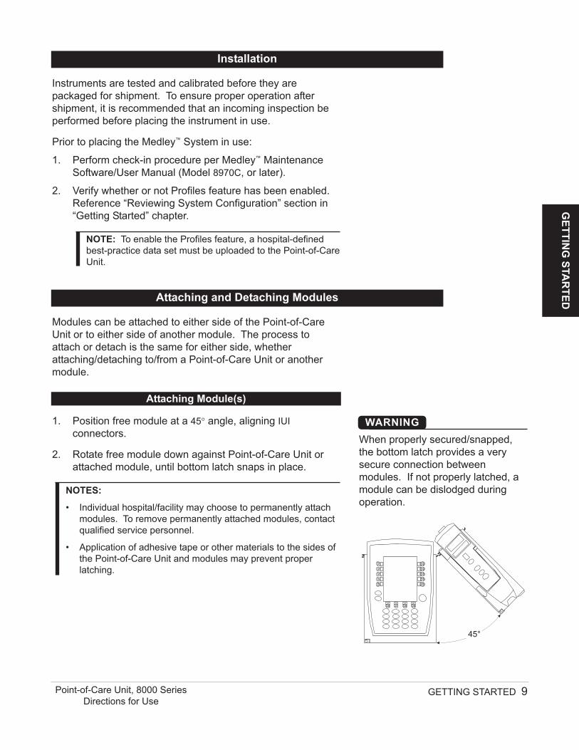
1. Position free module at a 45° angle, aligning IUIconnectors.
2. Rotate free module down against Point-of-Care Unit orattached module, until bottom latch snaps in place.
NOTES:
• Individual hospital/facility may choose to permanently attachmodules. To remove permanently attached modules, contactqualified service personnel.
• Application of adhesive tape or other materials to the sides ofthe Point-of-Care Unit and modules may prevent properlatching.
Modules can be attached to either side of the Point-of-CareUnit or to either side of another module. The process toattach or detach is the same for either side, whetherattaching/detaching to/from a Point-of-Care Unit or anothermodule.
Attaching and Detaching Modules
Attaching Module(s)
45°
When properly secured/snapped,the bottom latch provides a verysecure connection betweenmodules. If not properly latched, amodule can be dislodged duringoperation.
WARNING
Add module as described in “Attaching Module(s)”.
• System tests module, causing all LED segments andindicator lights of displays to illuminate briefly.
• Appropriate module identification display (A, B, C or D)illuminates. Modules are always labeled left to right, so if amodule is added to left of other modules, all modules willbe reidentified. Module reidentification does NOT interruptor affect infusion or monitoring on active modules.
• Module positions (A, B, C or D) appear on Main Display.
NOTE: If any of the following conditions are observed, theaffected module must be removed from use and inspected byqualified personnel:
• LED segments are not illuminated on displays during power-on test.
• Indicator lights do not illuminate.• Appropriate module identification (A, B, C or D) is not
displayed.
If the affected module operates normally when it is attached viathe alternate IUI connector, it may be used until a replacementmodule can be substituted.
10 GETTING STARTED Point-of-Care Unit, 8000 SeriesDirections for Use
Adding Module(s) While System is Powered On
IUI Connectors
Detaching Module(s)
1. Ensure module(s) is powered off before detaching.
2. Push module release latch (located directly below IUIconnectors) and then rotate module(s) up and away fromPoint-of-Care Unit or attached module (opposite to motionshown above) to disengage connectors.
• Medley™ System reidentifies and shows appropriatemodule identification (A, B, C or D), from left to right.
• Appropriate module position(s) (A, B or C) forremaining module(s) appear on Main Display.
NOTE: The Medley™ Medication Safety System is designed tooperate a maximum of 4 infusion or monitoring modules.Modules added in excess of 4 will not be recognized by thesystem. The module(s) can be attached in any position;however, when mounted on an IV pole, it is recommended that abalanced configuration be maintained.
Release Latch
Attaching and Detaching Modules (Continued)
GETTIN
G STA
RTED
GETTING STARTED 11Point-of-Care Unit, 8000 SeriesDirections for Use
VTBI = 250.0 mL
VOLUMEINFUSED
AUDIOADJUST
Midtown HospitalAdult ICU
The displays illustrated throughout this document are forillustration purposes only. The display content will vary,depending on configuration settings, hospital-defined data setuploaded using the Guardrails® Safety Software, and manyother variables.
1. Connect Point-of-Care Unit to an external AC powersource.
2. Press SYSTEM ON.
3. System self test begins:
• Diagnostics test causes all LED display segments andStatus Indicator lights of attached module(s) toilluminate briefly.
• Power Indicator illuminates.
• Appropriate module identification (A, B, C or D)displays on attached module(s).
• An Audio tone sounds.
12 GETTING STARTED Point-of-Care Unit, 8000 SeriesDirections for Use
Start-Up
Powering On System
Displays (Continued)
1. Press OPTIONS key.
2. Select Display Contrast soft key.
3. To adjust display for optimum viewing, useLighter/Darker soft keys.
4. To return to main screen, press MAIN SCREEN soft key.
System Options 1 of 3
>Select an Option orEXIT
PAGEDOWNEXIT
Display Contrast
Time of Day
Power Down All Channels
Anesthesia Mode
Patient ID
Adjusting Display Contrast
System Options
>Adjust Display toDesired Contrast
MAINSCREEN
Display Contrast
Lighter
DarkerMedley™
Medication Safety System
®
-- Continued on Next Page --
GETTIN
G STA
RTED
GETTING STARTED 13Point-of-Care Unit, 8000 SeriesDirections for Use
Start-Up (Continued)
Powering On System (Continued)
• At completion of system-on test, New Patient? screenappears.
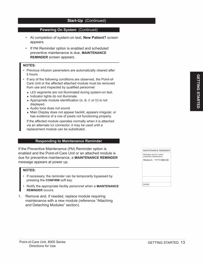
• If PM Reminder option is enabled and scheduledpreventive maintenance is due, MAINTENANCEREMINDER screen appears.
NOTES:• Previous infusion parameters are automatically cleared after
8 hours.• If any of the following conditions are observed, the Point-of-
Care Unit or the affected attached module must be removedfrom use and inspected by qualified personnel:♦ LED segments are not illuminated during system-on test.♦ Indicator lights do not illuminate.♦ Appropriate module identification (A, B, C or D) is not
displayed.♦ Audio tone does not sound.♦ Main Display does not appear backlit, appears irregular, or
has evidence of a row of pixels not functioning properly.If the affected module operates normally when it is attachedvia an alternate IUI connector, it may be used until areplacement module can be substituted.
If the Preventive Maintenance (PM) Reminder option isenabled and the Point-of-Care Unit or an attached module isdue for preventive maintenance, a MAINTENANCE REMINDERmessage appears at power up.
NOTES:
• If necessary, the reminder can be temporarily bypassed bypressing the CONFIRM soft key.
• Notify the appropriate facility personnel when a MAINTENANCEREMINDER occurs.
1. Remove and, if needed, replace module requiringmaintenance with a new module (reference “Attachingand Detaching Modules” section).
Responding to Maintenance Reminder
CONFIRM
B
MAINTENANCE REMINDER
Module(s) due for routinepreventive maintenance:
Module A: YYYY-MM-DD
14 GETTING STARTED Point-of-Care Unit, 8000 SeriesDirections for Use
Selecting New Patient and Profile Options
Start-Up (Continued)
The option to enter and display a 16-character alphanumericpatient identifier is always available. The instrument may beconfigured to automatically display the Patient ID Entryscreen during start up or to provide access only through theSystems Options menu.
The following procedures assume the Profiles feature isenabled.
NOTE: The display contrast can be adjusted at this time bypressing the DISPLAY CONTRST soft key and following thedirections on the screen (also reference “Displays”, “AdjustingDisplay Contrast” section).
CONFIRM
B
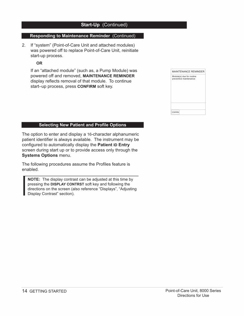
MAINTENANCE REMINDER
Module(s) due for routinepreventive maintenance:
Responding to Maintenance Reminder (Continued)
2. If “system” (Point-of-Care Unit and attached modules)was powered off to replace Point-of-Care Unit, reinitiatestart-up process.
OR
If an “attached module” (such as, a Pump Module) waspowered off and removed, MAINTENANCE REMINDERdisplay reflects removal of that module. To continuestart–up process, press CONFIRM soft key.
1. Select required NEW PATIENT? option.
To indicate programming is for a new patient and clear allstored patient parameters from memory, press Yes softkey.
OR
To confirm programming is for same patient and retain allstored patient parameters, press No soft key.
• Last used profile displays.
NOTE: If the Profiles feature is disabled, the main menuappears.
2. Select correct profile.
To accept current profile, press Yes soft key and proceedto step 5.
• Main screen appears.
OR
To change profile, press No soft key and continue withnext step.
• Profile selection screen appears.
3. To select a profile, press corresponding left soft key.
NOTE: To view additional choices, press PAGE DOWN softkey.
4. To confirm profile selection, press CONFIRM soft key.
• Main screen appears.
5. To enter Patient ID, if desired, reference “Entering PatientID” section.
GETTIN
G STA
RTED
GETTING STARTED 15Point-of-Care Unit, 8000 SeriesDirections for Use
Start-Up (Continued)
Patient ID Entry Feature Disabled
Midtown Hospital
Yes
No
NEW PATIENT ?
>Select Yes or No
“Yes” Clears PreviousPatient Data
DISPLAYCONTRST
Midtown HospitalAdult ICU
Yes
No
>Select Yes or No
Adult ICU ?
“Yes” Confirms SameProfile
Selecting New Patient and Profile Options (Continued)
Midtown HospitalProfiles
>Select a Profile andConfirm
CONFIRM PAGEDOWN
Neonatal
Peds ICU
Neonatal ICU
Adult General Care
Adult ICU
1 of 2
1. Select required NEW PATIENT? option.
• To indicate programming is for a new patient and clearall stored patient parameters from memory:
a. Press Yes soft key.
♦ Patient ID Entry screen appears.
b. If patient identifier is not required, press CONFIRMor EXIT soft key.
• To confirm programming is for same patient and retainall stored patient parameters, press No soft key.
♦ Last used profile displays.
NOTE: If the Profiles feature is disabled, the main menuappears.
2. Select correct profile.
To accept current profile, press Yes soft key.
• Main screen appears.
OR
To change profile, press No soft key and continue withnext step.
• Profile selection screen appears.
16 GETTING STARTED Point-of-Care Unit, 8000 SeriesDirections for Use
Start-Up (Continued)
Selecting New Patient and Profile Options (Continued)
EXIT
A
B
C
D
PAGEDOWN
>Enter Patient ID and PressCONFIRM
E
K-O
F-J
P-T
U-Y
A-E
Patient ID Entry
_ _ _ _ _ _ _ _ _ _ _ _ _ _ _ _
CONFIRM
Midtown HospitalAdult ICU
Yes
No
>Select Yes or No
Adult ICU ?
“Yes” Confirms SameProfile
Patient ID Entry Feature Enabled
Midtown Hospital
Yes
No
NEW PATIENT ?
>Select Yes or No
“Yes” Clears PreviousPatient Data
DISPLAYCONTRST
3. To select a profile, press corresponding left soft key.
NOTE: To view additional choices, press PAGE DOWN softkey.
4. To confirm profile selection, press CONFIRM soft key.
• Main screen appears. GETTIN
G STA
RTED
GETTING STARTED 17Point-of-Care Unit, 8000 SeriesDirections for Use
Start-Up (Continued)
Patient ID Entry Feature Enabled(Continued)
Entering Patient ID
Selecting New Patient and Profile Options (Continued)
When the Patient ID Entry feature is disabled, the Patient IDEntry screen can only be accessed through the SystemsOptions menu. To enter a patient ID, begin with step 1 of thefollowing procedure.
When the Patient ID Entry feature is enabled, the Patient IDEntry screen appears after responding Yes to New Patient?prompt. To enter a patient ID, begin with step 2 of thefollowing procedure.
1. To access Patient ID Entry screen:
a. Press OPTIONS key.
• System Options menu appears.
b. Press Patient ID soft key.
• Patient ID Entry screen appears.
System Options 1 of 3
>Select an Option orEXIT
PAGEDOWNEXIT
Display Contrast
Time of Day
Power Down All Channels
Anesthesia Mode
Patient ID
Midtown HospitalProfiles
>Select a Profile andConfirm
CONFIRM PAGEDOWN
Neonatal
Peds ICU
Neonatal ICU
Adult General Care
Adult ICU
1 of 2
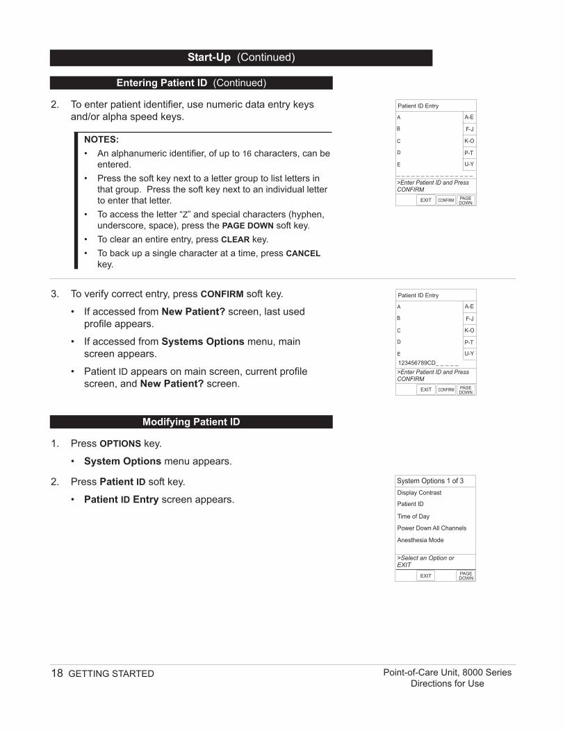
2. To enter patient identifier, use numeric data entry keysand/or alpha speed keys.
NOTES:• An alphanumeric identifier, of up to 16 characters, can be
entered.• Press the soft key next to a letter group to list letters in
that group. Press the soft key next to an individual letterto enter that letter.
• To access the letter “Z” and special characters (hyphen,underscore, space), press the PAGE DOWN soft key.
• To clear an entire entry, press CLEAR key.• To back up a single character at a time, press CANCEL
key.
3. To verify correct entry, press CONFIRM soft key.
• If accessed from New Patient? screen, last usedprofile appears.
• If accessed from Systems Options menu, mainscreen appears.
• Patient ID appears on main screen, current profilescreen, and New Patient? screen.
18 GETTING STARTED Point-of-Care Unit, 8000 SeriesDirections for Use
Entering Patient ID (Continued)
EXIT
A
B
C
D
PAGEDOWN
>Enter Patient ID and PressCONFIRM
E
K-O
F-J
P-T
U-Y
A-E
Patient ID Entry
_ _ _ _ _ _ _ _ _ _ _ _ _ _ _ _
CONFIRM
EXIT
A
B
C
D
PAGEDOWN
>Enter Patient ID and PressCONFIRM
E
K-O
F-J
P-T
U-Y
A-E
Patient ID Entry
123456789CD_ _ _ _ _
CONFIRM
Start-Up (Continued)
Modifying Patient ID
1. Press OPTIONS key.
• System Options menu appears.
2. Press Patient ID soft key.
• Patient ID Entry screen appears.
System Options 1 of 3
>Select an Option orEXIT
PAGEDOWNEXIT
Display Contrast
Time of Day
Power Down All Channels
Anesthesia Mode
Patient ID
3. To clear entire entry, press CLEAR key.
OR
To back up a single character at a time, press CANCELkey.
4. To enter modified patient identifier, use numeric data entrykeys and/or alpha speed keys.
NOTES:• An alphanumeric identifier, of up to 16 characters, can be
entered.• Press the soft key next to a letter group to list letters in
that group. Press the soft key next to an individual letterto enter that letter.
• To access the letter “Z” and special characters (hyphen,underscore, space), press the PAGE DOWN soft key.
5. To verify correct entry, press CONFIRM soft key.
• Patient ID Entry verification screen appears.
6. To accept modified Patient ID, press Yes soft key.
• Main screen appears with new Patient ID.
OR
To retain original (old) Patient ID, press No soft key.
• Main screen appears with old Patient ID.
GETTIN
G STA
RTED
GETTING STARTED 19Point-of-Care Unit, 8000 SeriesDirections for Use
Start-Up (Continued)
Modifying Patient ID (Continued)
EXIT
A
B
C
D
PAGEDOWN
>Enter Patient ID and PressCONFIRM
E
K-O
F-J
P-T
U-Y
A-E
Patient ID Entry
123456789CD
CONFIRM
EXIT
A
B
C
D
PAGEDOWN
>Enter Patient ID and PressCONFIRM
E
K-O
F-J
P-T
U-Y
A-E
Patient ID Entry
_ _ _ _ _ _ _ _ _ _ _ _ _ _ _ _
CONFIRM
EXIT
A
B
C
D
PAGEDOWN
>Enter Patient ID and PressCONFIRM
E
K-O
F-J
P-T
U-Y
A-E
Patient ID Entry
234567891EF_ _ _ _ _
CONFIRM
>Press Yes or No
Patient ID Entry
Yes
No
Patient ID
123456789CD
will be changed to
234567891EF
Is this correct?
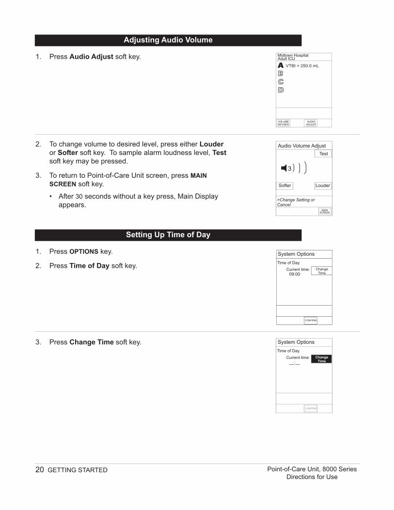
1. Press Audio Adjust soft key.
2. To change volume to desired level, press either Louderor Softer soft key. To sample alarm loudness level, Testsoft key may be pressed.
3. To return to Point-of-Care Unit screen, press MAINSCREEN soft key.
• After 30 seconds without a key press, Main Displayappears.
20 GETTING STARTED Point-of-Care Unit, 8000 SeriesDirections for Use
1. Press OPTIONS key.
2. Press Time of Day soft key.
3. Press Change Time soft key.
Setting Up Time of Day
Time of Day
System Options
Current time:09:00
ChangeTime
CONFIRM
Time of Day
System Options
Current time:__:__
ChangeTime
CONFIRM
Adjusting Audio Volume
Louder
>Change Setting orCancel
Audio Volume Adjust
Test
Softer
MAINSCREEN
3
VTBI = 250.0 mL
VOLUMEINFUSED
AUDIOADJUST
Midtown HospitalAdult ICU
1. Press OPTIONS key.
2. Press PAGE DOWN soft key.
3. Press System Configuration soft key.
4. Select PC Unit.
5. To review various system configuration settings, pressPAGE UP and PAGE DOWN soft keys.
NOTES:• The Profiles option is listed only if it is disabled.• The Dose Checking option is listed only if the Profiles
option is enabled and a valid data set is present.
GETTIN
G STA
RTED
GETTING STARTED 21Point-of-Care Unit, 8000 SeriesDirections for Use
4. Enter current Time of Day.
5. Press Confirm soft key.
NOTE: The format is a 24-hour clock (military time).
Time of Day
System Options
Current time:14:30
ChangeTime
CONFIRM
Reviewing System Configuration
Factory Default: Yes
System Config - Module 1 of 2
PC Unit
Pump Module
SPO2 Module
>Press CANCEL or EXIT
EXIT
Shared Infusion Settings
PAGEDOWN
Setting Up Time of Day (Continued)
>Select an Optionor EXIT
PAGEDOWNEXIT
System Config - PCU 1 of 2
Alarm audio: Profile 1
Battery meter: Disabled
Clock setup: 09:00
Key click audio: Enabled
Anesthesia Mode: Disabled
>Select an Optionor EXIT
EXITPAGE
UP
System Config - PCU 2 of 2
Profiles:
Tamper resist:
500 kgMax Pt. weight:
Patient ID Entry: Disabled
PM Reminder: Disabled
Disabled
Disabled
6. To return to main screen, press CANCEL key or EXIT softkey.
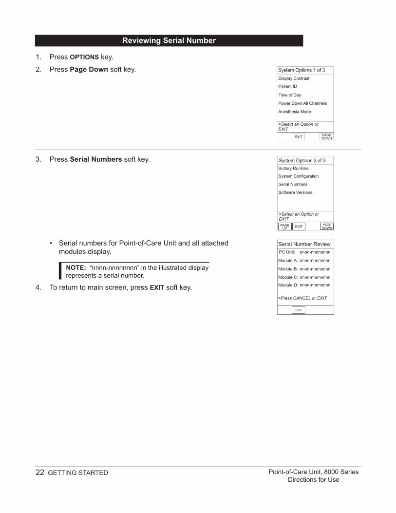
1. Press OPTIONS key.
2. Press Page Down soft key.
3. Press Serial Numbers soft key.
• Serial numbers for Point-of-Care Unit and all attachedmodules display.
NOTE: “nnnn-nnnnnnnn” in the illustrated displayrepresents a serial number.
4. To return to main screen, press EXIT soft key.
22 GETTING STARTED Point-of-Care Unit, 8000 SeriesDirections for Use
Reviewing Serial Number
Serial Number Review
PC Unit: nnnn-nnnnnnnn
nnnn-nnnnnnnn
nnnn-nnnnnnnn
nnnn-nnnnnnnn
nnnn-nnnnnnnn
Module A:
Module B:
Module C:
Module D:
>Press CANCEL or EXIT
EXIT
System Options 2 of 3
PAGEUP
System Configuration
>Select an Option orEXIT
EXIT
Software Versions
Serial Numbers
Battery Runtime
PAGEDOWN
System Options 1 of 3
>Select an Option orEXIT
PAGEDOWNEXIT
Display Contrast
Time of Day
Power Down All Channels
Anesthesia Mode
Patient ID
1. Press OPTIONS key.
2. Press PAGE DOWN soft key.
3. Press Software Versions soft key.
4. To review software version information, press View softkey next to desired module.
OR
To return to main screen, press EXIT soft key
5. To return to previous screen, press EXIT soft key.
NOTE: “nn.nn” in the illustrated display represents asoftware version.
GETTIN
G STA
RTED
GETTING STARTED 23Point-of-Care Unit, 8000 SeriesDirections for Use
Reviewing Software Version
System Options 2 of 3
PAGEUP
System Configuration
>Select an Option orEXIT
EXIT
Software Versions
Serial Numbers
Battery Runtime
PAGEDOWN
Software Rev. Review
PC Unit:
Module A:
Module B:
Module C:
Module D:
View
View
View
View
View
>Select an Option orEXIT
EXIT
EXIT
>Press CANCEL or EXIT
Software Rev. Review
Module Software: A
Main processor: nn.nn
nn.nn
nn.nn
Main boot block:
Keyboard:
System Options 1 of 3
>Select an Option orEXIT
PAGEDOWNEXIT
Display Contrast
Time of Day
Power Down All Channels
Anesthesia Mode
Patient ID
1. Press OPTIONS key.
2. Press Power Down All Channels soft key.
3. Press Yes soft key.
• During power off sequence, Main Display flashesPOWERING DOWN.
24 GETTING STARTED Point-of-Care Unit, 8000 SeriesDirections for Use
Powering Off
Powering Off System
System Options
Yes
No
Power DownAll Channels?
>Press Yes or No
System Options 1 of 3
>Select an Option orEXIT
PAGEDOWNEXIT
Display Contrast
Time of Day
Power Down All Channels
Anesthesia Mode
Patient ID
Press and hold CHANNEL OFF key until a beep is heard(approximately 1.5 seconds) and then release to initiate powerdown.
NOTE: To interrupt the power down sequence, quickly press anyone of the numeric keys on the Point-of-Care Unit.
• During power off sequence, Main Display flashesPowering Down.
• Once all attached modules are powered off, Point-of-CareUnit automatically powers down.
Powering Off Module
Powering Down
1. Initiate operation of desired modules.
2. Press and hold Tamper Resist Switch, on back of Point-of-Care Unit, for 3 to 4 seconds. An advisory tone and athree-second PANEL LOCKED prompt on Main Displayconfirm activation. When Tamper Resist is active, keypadpanel is locked; however, clinician may:
• Silence key for audio alarm.• View volume(s) infused.• View and test audio alarm setting.• View selected parameters on attached modules.
Any other key press will result in a visual PANEL LOCKEDprompt and, if Key Click Audio is enabled, an illegalkey–press audio advisory.
3. To unlock keypad panel, press and hold Tamper ResistSwitch for 3 to 4 seconds. A three-second PANELUNLOCKED prompt on Main Display and, if Key ClickAudio is enabled, an advisory tone confirms TamperResist is off.
GETTIN
G STA
RTED
GETTING STARTED 25Point-of-Care Unit, 8000 SeriesDirections for Use
Locking/Unlocking Tamper Resist
PANEL LOCKED
VTBI = 250.0 mL
VOLUMEINFUSED
AUDIOADJUST
Midtown HospitalAdult ICU
PANEL UNLOCKED
VTBI = 250.0 mL
VOLUMEINFUSED
AUDIOADJUST
Midtown HospitalAdult ICU
26 GETTING STARTED Point-of-Care Unit, 8000 SeriesDirections for Use
T H I S PA G EI N T E N T I O N A L LY
L E F T B L A N K
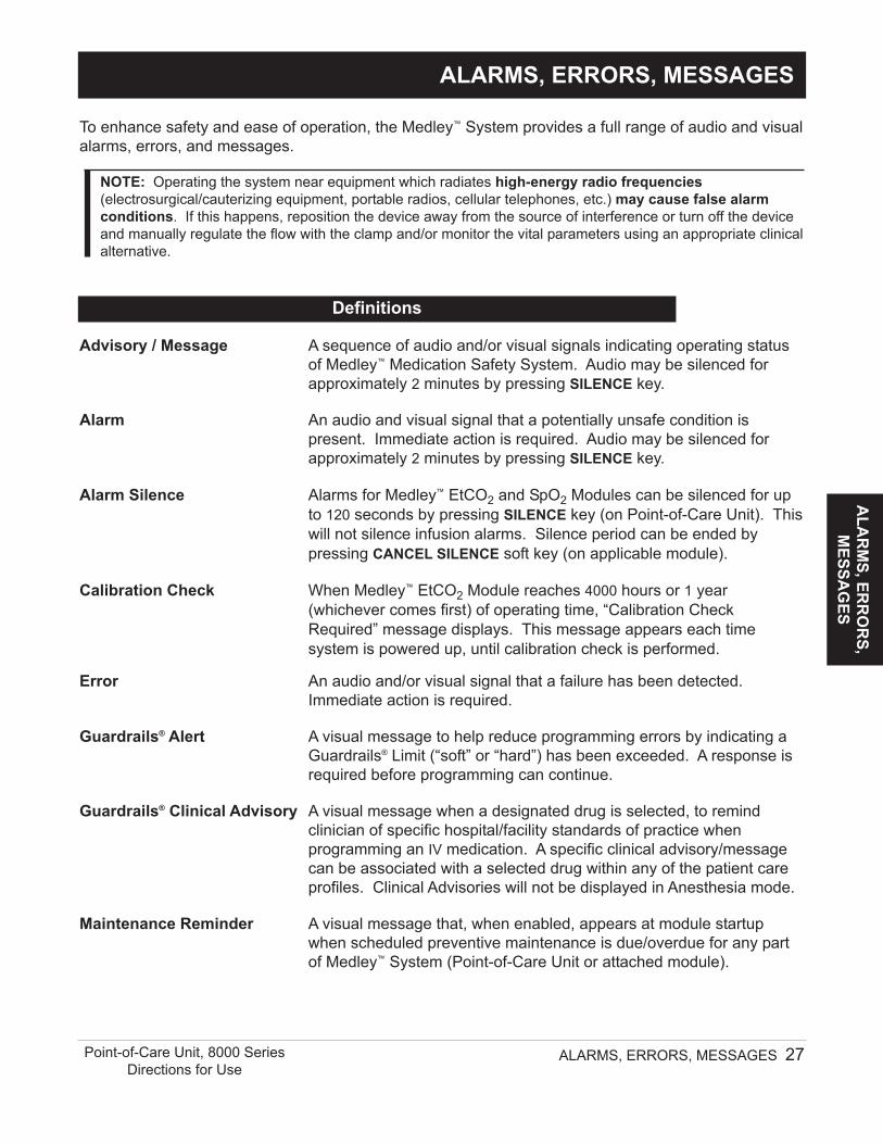
Advisory / Message A sequence of audio and/or visual signals indicating operating statusof Medley™ Medication Safety System. Audio may be silenced forapproximately 2 minutes by pressing SILENCE key.
Alarm An audio and visual signal that a potentially unsafe condition ispresent. Immediate action is required. Audio may be silenced forapproximately 2 minutes by pressing SILENCE key.
Alarm Silence Alarms for Medley™ EtCO2 and SpO2 Modules can be silenced for upto 120 seconds by pressing SILENCE key (on Point-of-Care Unit). Thiswill not silence infusion alarms. Silence period can be ended bypressing CANCEL SILENCE soft key (on applicable module).
Calibration Check When Medley™ EtCO2 Module reaches 4000 hours or 1 year(whichever comes first) of operating time, “Calibration CheckRequired” message displays. This message appears each timesystem is powered up, until calibration check is performed.
Error An audio and/or visual signal that a failure has been detected.Immediate action is required.
Guardrails® Alert A visual message to help reduce programming errors by indicating aGuardrails® Limit (“soft” or “hard”) has been exceeded. A response isrequired before programming can continue.
Guardrails® Clinical Advisory A visual message when a designated drug is selected, to remindclinician of specific hospital/facility standards of practice whenprogramming an IV medication. A specific clinical advisory/messagecan be associated with a selected drug within any of the patient careprofiles. Clinical Advisories will not be displayed in Anesthesia mode.
Maintenance Reminder A visual message that, when enabled, appears at module startupwhen scheduled preventive maintenance is due/overdue for any partof Medley™ System (Point-of-Care Unit or attached module).
ALARMS, ERRORS, MESSAGES
ALA
RM
S, ERR
OR
S, M
ESSAG
ES
ALARMS, ERRORS, MESSAGES 27
Definitions
Point-of-Care Unit, 8000 SeriesDirections for Use
To enhance safety and ease of operation, the Medley™ System provides a full range of audio and visualalarms, errors, and messages.
NOTE: Operating the system near equipment which radiates high-energy radio frequencies(electrosurgical/cauterizing equipment, portable radios, cellular telephones, etc.) may cause false alarmconditions. If this happens, reposition the device away from the source of interference or turn off the deviceand manually regulate the flow with the clamp and/or monitor the vital parameters using an appropriate clinicalalternative.
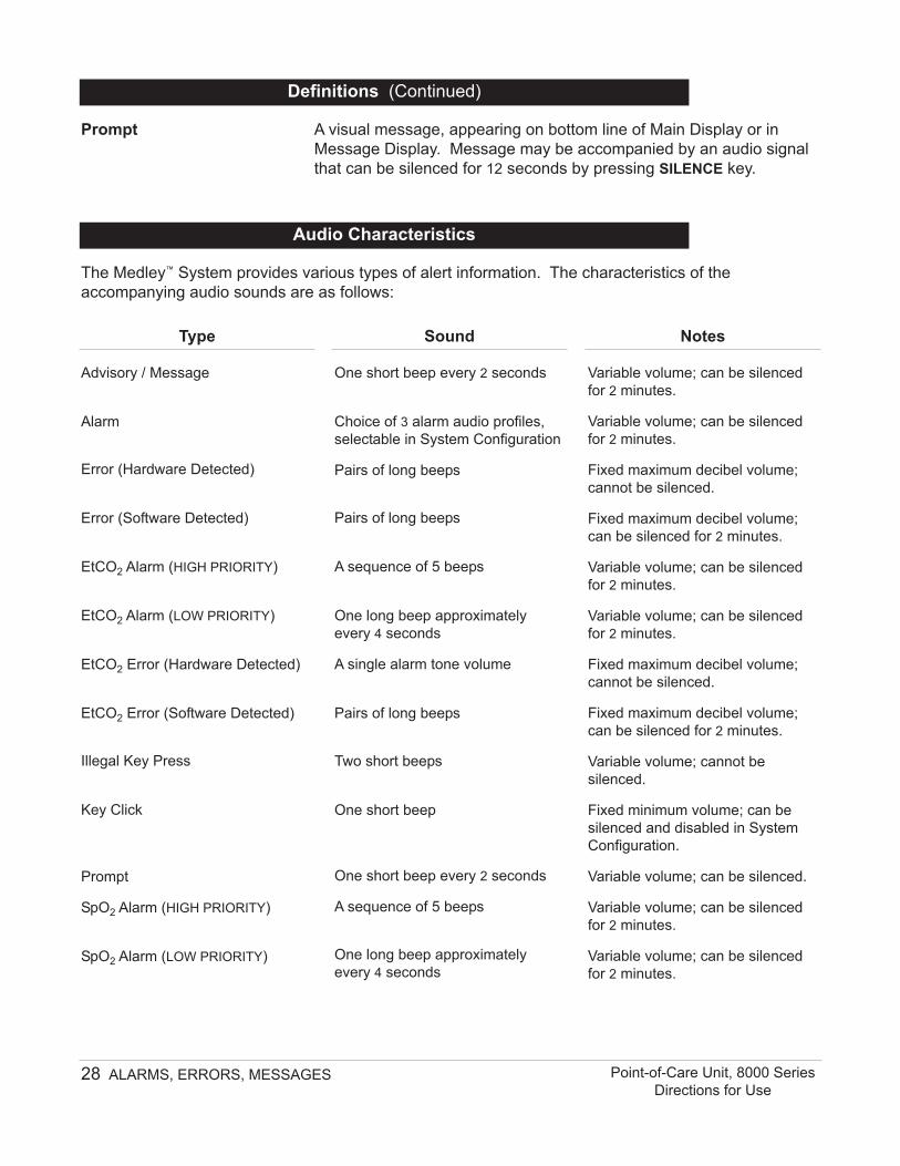
Advisory / Message
Alarm
Error (Hardware Detected)
Error (Software Detected)
EtCO2 Alarm (HIGH PRIORITY)
EtCO2 Alarm (LOW PRIORITY)
EtCO2 Error (Hardware Detected)
EtCO2 Error (Software Detected)
Illegal Key Press
Key Click
Prompt
SpO2 Alarm (HIGH PRIORITY)
SpO2 Alarm (LOW PRIORITY)
One short beep every 2 seconds
Choice of 3 alarm audio profiles,selectable in System Configuration
Pairs of long beeps
Pairs of long beeps
A sequence of 5 beeps
One long beep approximatelyevery 4 seconds
A single alarm tone volume
Pairs of long beeps
Two short beeps
One short beep
One short beep every 2 seconds
A sequence of 5 beeps
One long beep approximatelyevery 4 seconds
Variable volume; can be silencedfor 2 minutes.
Variable volume; can be silencedfor 2 minutes.
Fixed maximum decibel volume;cannot be silenced.
Fixed maximum decibel volume;can be silenced for 2 minutes.
Variable volume; can be silencedfor 2 minutes.
Variable volume; can be silencedfor 2 minutes.
Fixed maximum decibel volume;cannot be silenced.
Fixed maximum decibel volume;can be silenced for 2 minutes.
Variable volume; cannot besilenced.
Fixed minimum volume; can besilenced and disabled in SystemConfiguration.
Variable volume; can be silenced.
Variable volume; can be silencedfor 2 minutes.
Variable volume; can be silencedfor 2 minutes.
28 ALARMS, ERRORS, MESSAGES Point-of-Care Unit, 8000 SeriesDirections for Use
Audio Characteristics
The Medley™ System provides various types of alert information. The characteristics of theaccompanying audio sounds are as follows:
Type Sound Notes
Definitions (Continued)
Prompt A visual message, appearing on bottom line of Main Display or inMessage Display. Message may be accompanied by an audio signalthat can be silenced for 12 seconds by pressing SILENCE key.
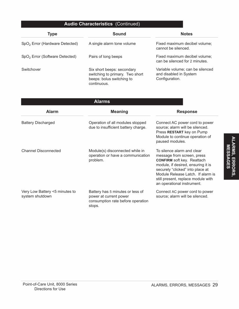
Battery Discharged
Channel Disconnected
Very Low Battery <5 minutes tosystem shutdown
Operation of all modules stoppeddue to insufficient battery charge.
Module(s) disconnected while inoperation or have a communicationproblem.
Battery has 5 minutes or less ofpower at current powerconsumption rate before operationstops.
Connect AC power cord to powersource; alarm will be silenced.Press RESTART key on PumpModule to continue operation ofpaused modules.
To silence alarm and clearmessage from screen, pressCONFIRM soft key. Reattachmodule, if desired, ensuring it issecurely “clicked” into place atModule Release Latch. If alarm isstill present, replace module withan operational instrument.
Connect AC power cord to powersource; alarm will be silenced.
ALA
RM
S, ERR
OR
S, M
ESSAG
ES
ALARMS, ERRORS, MESSAGES 29Point-of-Care Unit, 8000 SeriesDirections for Use
Alarms
Alarm Meaning Response
SpO2 Error (Hardware Detected)
SpO2 Error (Software Detected)
Switchover
A single alarm tone volume
Pairs of long beeps
Six short beeps: secondaryswitching to primary. Two shortbeeps: bolus switching tocontinuous.
Fixed maximum decibel volume;cannot be silenced.
Fixed maximum decibel volume;can be silenced for 2 minutes.
Variable volume; can be silencedand disabled in SystemConfiguration.
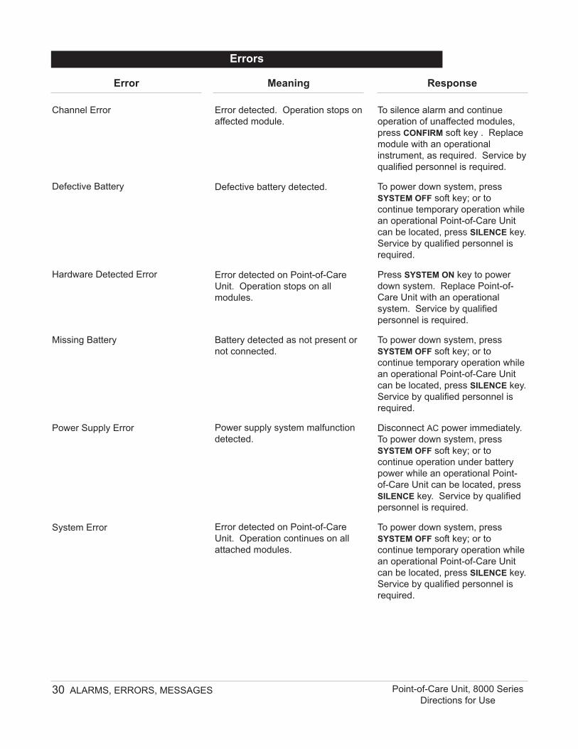
Error detected on Point-of-CareUnit. Operation stops on allmodules.
Battery detected as not present ornot connected.
Power supply system malfunctiondetected.
Error detected on Point-of-CareUnit. Operation continues on allattached modules.
To silence alarm and continueoperation of unaffected modules,press CONFIRM soft key . Replacemodule with an operationalinstrument, as required. Service byqualified personnel is required.
To power down system, pressSYSTEM OFF soft key; or tocontinue temporary operation whilean operational Point-of-Care Unitcan be located, press SILENCE key.Service by qualified personnel isrequired.
Press SYSTEM ON key to powerdown system. Replace Point-of-Care Unit with an operationalsystem. Service by qualifiedpersonnel is required.
To power down system, pressSYSTEM OFF soft key; or tocontinue temporary operation whilean operational Point-of-Care Unitcan be located, press SILENCE key.Service by qualified personnel isrequired.
Disconnect AC power immediately.To power down system, pressSYSTEM OFF soft key; or tocontinue operation under batterypower while an operational Point-of-Care Unit can be located, pressSILENCE key. Service by qualifiedpersonnel is required.
To power down system, pressSYSTEM OFF soft key; or tocontinue temporary operation whilean operational Point-of-Care Unitcan be located, press SILENCE key.Service by qualified personnel isrequired.
30 ALARMS, ERRORS, MESSAGES Point-of-Care Unit, 8000 SeriesDirections for Use
Errors
Error Meaning Response
ALA
RM
S, ERR
OR
S, M
ESSAG
ES
ALARMS, ERRORS, MESSAGES 31Point-of-Care Unit, 8000 SeriesDirections for Use
Battery Run Time = X.X hours
Low Battery
Panel Locked
Panel Unlocked
Powering Down
Replace Battery
AC power cord is disconnectedfrom power source. Approximateremaining battery run time undercurrent power consumption rate isdisplayed.
Low battery threshold sensed;remaining battery run time islimited.
Tamper Resist feature is active andkey was pressed.
Tamper Resist feature deactivated.
Last module powering off. Systemshuts off in indicated number ofseconds.
Occurs at System On. Battery hasless than 50% of original capacity.
None. Connect AC power cord topower source as soon as possible.
Connect AC power cord to powersource; alarm will be silenced.
If appropriate, deactivate TamperResist feature using Tamper ResistControl on back of Point-of-CareUnit.
None.
Press any key, except SYSTEM ONkey, to cancel power downsequence.
Press either SYSTEM OFF orCONFIRM soft key to continuenormal operation with reducedbattery capacity. Service byqualified personnel is required.
Messages
Message Meaning Response
32 ALARMS, ERRORS, MESSAGES Point-of-Care Unit, 8000 SeriesDirections for Use
T H I S PA G EI N T E N T I O N A L LY
L E F T B L A N K
Battery Operation: Battery run time is a function of the number of modules attached and moduleactivity. With a new, fully charged battery, the system will operate as followsbefore a "BATTERY DISCHARGED" message occurs:• 8 hours with 1 Pump Module infusing at 25 mL/h• 4 hours with 4 Pump Modules infusing at 25 mL/h• 6 hours with 1 active SpO2 Module• 8 hours with 1 Syringe Module or PCA Module infusing at 5 mL/h• 4 hours with 4 Syringe Modules infusing at 5 mL/h• 5.5 hours with 1 active EtCO2 Module
Communication Data Port: RS-232 with an RJ45 connector.
Dimensions: 6.9"W x 8.8"H x 9"D (including pole clamp)
Electric Classification: Class 1, Internally Powered Equipment
NOTE: Reference module-specific Directions for Use for shock protection typeand defibrillation-proof rating information.
Electronic Memory: System configuration parameters stored in volatile memory are retained for atleast 6 months by internal backup lithium battery. Module-specific parameters arestored for 8 hours when system is turned off. After 8 hours of continuous off-time,or if a module is detached, module-specific trend data (if applicable) and module-specific operating parameters are automatically purged. If a Medley™ PCA, SpO2or EtCO2 module is detached and replaced with another PCA, SpO2 or EtCO2module, its module-specific trend data is purged.
Temperature Range: 41 to 104°F -4 to 140°F(5 to 40°C) (-20 to 60°C)
Relative Humidity: 20 to 90% 5 to 85%(Avoid prolonged exposure Noncondensing Noncondensingto relative humidity >85%)
Atmospheric Pressure: 525 to 4560 mmHg 375 to 760 mmHg(700 to 6080 hPa) (500 to 1013 hPa)
Equipment Orientation: To ensure proper operation, the instrument must remain in an upright position.
Fluid Ingress Protection: IPX1, Drip Proof
Leakage Current: Less than 100 microamps
The Medley™ System Technical Service Manual is available from ALARIS Medical Systems. It includesroutine service schedules, interconnect diagrams, component parts lists and descriptions, testprocedures, and other technical information, to assist qualified service personnel in repair andmaintenance of the instrument’s repairable components. Maintenance procedures are intended to beperformed only by qualified personnel, using the service manual and Medley™ Maintenance Software.
MA
INTEN
AN
CE
MAINTENANCE
MAINTENANCE 33Point-of-Care Unit, 8000 SeriesDirections for Use
Specifications
NOTES:1. Power Cords; North America: To ensure correct polarity and grounding reliability, use power cords that
incorporate a NEMA 5-15P (125V) or NEMA 6-15P (250V) plug only.2. Power Cords; International: Use only cords that comply with IEC 60245, or IEC 60227, designation #53 and
local electrical codes and/or regulations.3. Compliance to Standards: The Medley™ Medication Safety System has been assessed and complies with
the following standards: UL 60601–1; CSA C22.2 No. 601.1, including A1 and A2; IEC/EN 60601–2–24;IEC/EN 60601–1–2 and AAMI ID26.
34 MAINTENANCE Point-of-Care Unit, 8000 SeriesDirections for Use
Specifications (Continued)
System Configurable Settings
Profile 1, 2 or 3
Enabled - Disabled
Enabled - Disabled
Set date and time
Always, Smart
Enabled - Disabled
0.1 - 500 kg
Enabled - Disabled
Enabled - Disabled
Enabled - Disabled
Enabled - Disabled
Feature
Alarm Audio
Anesthesia Mode
Battery Meter
Clock Setup (Date and Time)
Dose Checking
Key Click Audio
Max Patient Weight
Patient ID Entry
PM Reminder(Preventive Maintenance)
Profiles
Tamper Resist
Default Setting Options
Profile 1
Disabled
Disabled
N/A
Always
Enabled
500 kg
Disabled
Enabled
Disabled
Disabled
If the configuration settings need to be changed from the"Factory Default" settings, reference the applicable TechnicalService Manual or contact ALARIS Medical Systems, TechnicalSupport, for technical, troubleshooting, and preventivemaintenance information.
NOTE: With the Profiles feature enabled, the settings areconfigured independently for each profile. A hospital-defined, best-practice data set must be uploaded to enable the Profiles feature.Date and Time is a system setting and is the same in all profiles.
Power Requirements: 100 - 240V ~, 50/60 Hz, 150 VA MAX (See Notes 1 and 2)
Weight: 7.2 lbs
The Medley™ Point-of-Care Unit is equipped with a 12 volt,4000 mAh nickel metal hydride battery. The battery ischarging whenever the instrument is plugged into an ACreceptacle. The life expectancy of the battery is dependent onthe amount of use, the depth of discharge, and the state of thecharge that is maintained. Generally, the battery will have thelongest life if the instrument is plugged in and battery use isinfrequent. Frequent use of battery power and insufficientbattery charge cycles will significantly decrease the life of thebattery.
The quality of the battery is also a significant factor indetermining battery life and runtime. The battery cannot berepaired and should not be opened. Replace the battery withthe same type, size and voltage rating. Use of any otherbrand may yield poor performance and is not recommended.
Batteries should be charged in a room with a temperaturebetween 50 - 80.6°F (10 - 27°C), to minimize charge time andmaximize battery life.
MA
INTEN
AN
CE
MAINTENANCE 35Point-of-Care Unit, 8000 SeriesDirections for Use
Plug the Point-of-Care Unit into an AC outlet during storage, toensure a fully charged battery when needed.
(AC indicator light) will be on whenever the Point-of-CareUnit is plugged in.
Battery Care and Maintenance
Battery Type and Charging
Storage
Battery Charge
• The Medley™ Point-of-Care Unit is shipped with the batteryin a discharged condition.
• Before the Point-of-Care Unit is released for use, it shouldbe plugged into a hospital grade AC outlet and the batterycharged for at least 8 hours. This will ensure properbattery operation when the Medley™ System is first set upfor patient use.
• Whenever possible, leave the power cord connected to anexternal AC power source while operating the instrument.
The battery capacity should be checked at least once every6 months. Reference the Medley™ System Technical ServiceManual for test and replacement procedures.
If the Point-of-Care Unit is to be stored at temperatures inexcess of 86°F (30°C) for 1 or more months, the battery shouldbe removed and placed in an environment of 50 – 86°F(10 – 30°C).
If the batteries are to be stored for more than 1 year, theyshould be charged at least once per year to prevent leakageand deterioration in performance due to self-discharge.
When the battery is first being put into use, or has been out ofuse for 1 or more months, it will not have full capacity due todeactivation of reactants.
Restore such batteries to original performance by repeating1 or 2 cycles of fully charging and fully discharging.
Some temporary reduction in capacity might become apparentif the battery is partially discharged repeatedly. Doing 1 or2 cycles of full discharge and full charge can restore fullperformance.
36 MAINTENANCE Point-of-Care Unit, 8000 SeriesDirections for Use
Battery Care and Maintenance (Continued)
Battery Care
Battery Cautions and Disposal
Battery replacement should be performed by qualified servicepersonnel while the instrument is not in use.
DO NOT open, incinerate or shortcircuit. Worn–out batteries must bedisposed of properly, according tolocal regulations.
CAUTION
MA
INTEN
AN
CE
MAINTENANCE 37Point-of-Care Unit, 8000 SeriesDirections for Use
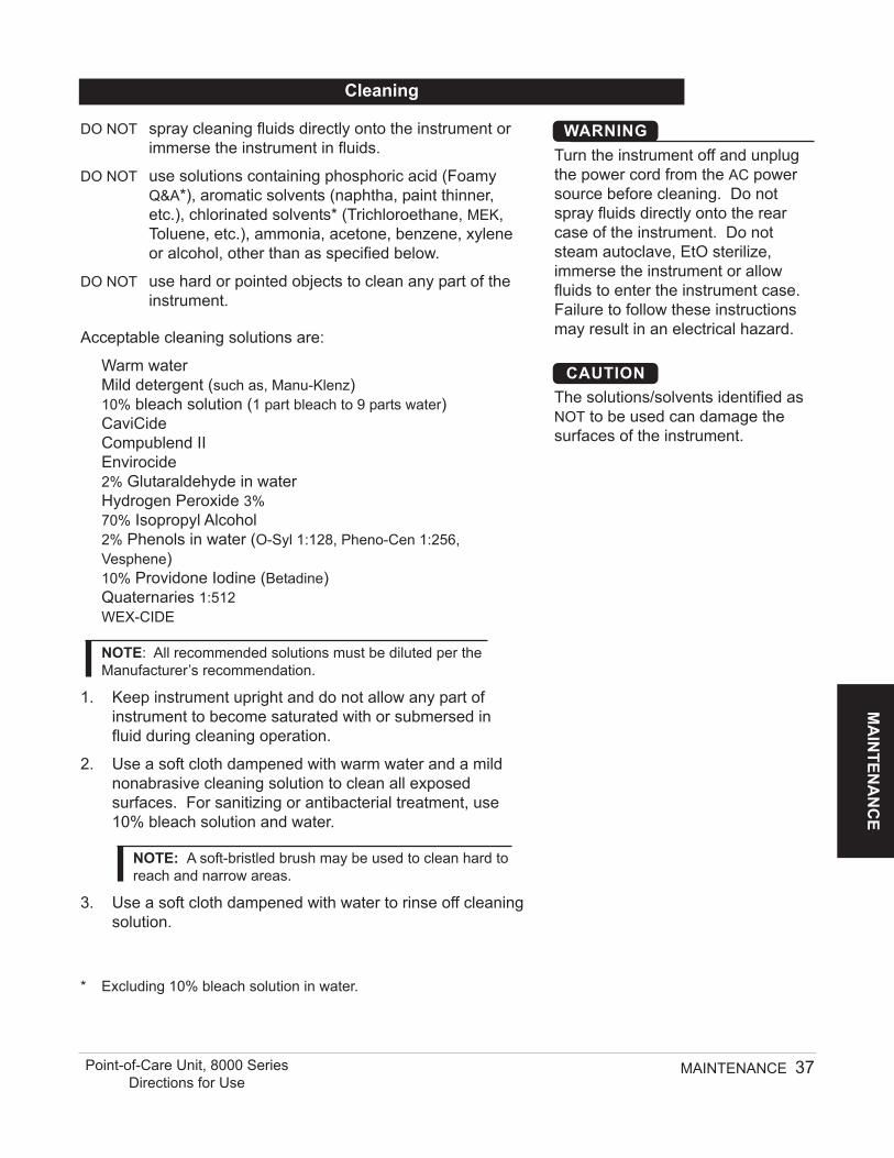
DO NOT spray cleaning fluids directly onto the instrument orimmerse the instrument in fluids.
DO NOT use solutions containing phosphoric acid (FoamyQ&A*), aromatic solvents (naphtha, paint thinner,etc.), chlorinated solvents* (Trichloroethane, MEK,Toluene, etc.), ammonia, acetone, benzene, xyleneor alcohol, other than as specified below.
DO NOT use hard or pointed objects to clean any part of theinstrument.
Acceptable cleaning solutions are:
Warm waterMild detergent (such as, Manu-Klenz)10% bleach solution (1 part bleach to 9 parts water)CaviCideCompublend IIEnvirocide2% Glutaraldehyde in waterHydrogen Peroxide 3%70% Isopropyl Alcohol2% Phenols in water (O-Syl 1:128, Pheno-Cen 1:256,Vesphene)10% Providone Iodine (Betadine)Quaternaries 1:512WEX-CIDE
NOTE: All recommended solutions must be diluted per theManufacturer’s recommendation.
1. Keep instrument upright and do not allow any part ofinstrument to become saturated with or submersed influid during cleaning operation.
2. Use a soft cloth dampened with warm water and a mildnonabrasive cleaning solution to clean all exposedsurfaces. For sanitizing or antibacterial treatment, use10% bleach solution and water.
NOTE: A soft-bristled brush may be used to clean hard toreach and narrow areas.
3. Use a soft cloth dampened with water to rinse off cleaningsolution.
* Excluding 10% bleach solution in water.
Cleaning
Turn the instrument off and unplugthe power cord from the AC powersource before cleaning. Do notspray fluids directly onto the rearcase of the instrument. Do notsteam autoclave, EtO sterilize,immerse the instrument or allowfluids to enter the instrument case.Failure to follow these instructionsmay result in an electrical hazard.
WARNING
The solutions/solvents identified asNOT to be used can damage thesurfaces of the instrument.
CAUTION
To ensure the system remains in good operating condition,both regular and preventive maintenance inspections arerequired. Reference the Medley™ Maintenance Software/UserManual (Model 8970C, or later) for detailed instructions.
REGULAR INSPECTIONSPROCEDURE FREQUENCYINSPECT FOR DAMAGE:
Exterior Surface Each usagePole Clamp Each usagePower Cord Each usageKeypad Each usage
CLEANING As requiredStart-Up Each usage
38 MAINTENANCE Point-of-Care Unit, 8000 SeriesDirections for Use
NOTE: If the instrument shows evidence of damage in transit,notify the carrier’s agent immediately. Do not return damagedequipment to the factory before the carrier’s agent hasauthorized repairs.
If the instrument fails to respond as described in thisdocument and the cause cannot be determined, do not usethe instrument. Contact qualified ALARIS Medical Systemsservice personnel.
If it is necessary to return the instrument for service, obtain areturn authorization number prior to shipment. Carefullypackage the instrument (preferably in the original packaging),reference the return authorization information, and return it tothe appropriate service or distribution center. ALARIS MedicalSystems does not assume any responsibility for loss of, ordamage to, returned instruments while in transit.
Service Information
During servicing, an instrument’sconfiguration settings might be resetto the factory defaults. Qualifiedhospital/facility personnel areresponsible for checking in theinstrument and ensuring the currenthospital-approved data set isloaded.
WARNING
Inspection Requirements
Failure to perform these inspectionsmay result in improper instrumentoperation.
WARNING
Regular and preventivemaintenance inspections shouldonly be performed by qualifiedservice personnel.
CAUTION
Technical support, service information, applications, andmanuals may be obtained by contacting an ALARIS MedicalSystems representative.
When submitting any request for service, include:
• Model number• a description of difficulty experienced• instrument settings• administration set/lot number• solution(s) used• message displayed at time of difficulty
MA
INTEN
AN
CE
MAINTENANCE 39Point-of-Care Unit, 8000 SeriesDirections for Use
Service Information (Continued)
Technical Support
ALARIS Medical Systems, Inc., (hereinafter referred to as “ALARIS Medical Systems”) warrantsthat:
A. Each new ALARIS Medical Systems® Medley™ Point-of-Care Unit is free from defects inmaterial and workmanship under normal use and service for a period of one (1) year from thedate of delivery by ALARIS Medical Systems to the original purchaser.
B. The battery and each new accessory is free from defects in material and workmanship undernormal use and service for a period of ninety (90) days from the date of delivery by ALARISMedical Systems to the original purchaser.
If any product requires service during the applicable warranty period, the purchaser shouldcommunicate directly with the relevant account representative to determine the appropriate repairfacility. Except as provided otherwise in this warranty, repair or replacement will be carried out atALARIS Medical Systems’ expense. The product requiring service should be returned promptly,properly packaged and postage prepaid by purchaser. Loss or damage in return shipment to therepair facility shall be at purchaser’s risk.
In no event shall ALARIS Medical Systems be liable for any incidental, indirect or consequentialdamages in connection with the purchase or use of any ALARIS Medical Systems® Product. Thiswarranty shall apply solely to the original purchaser. This warranty shall not apply to anysubsequent owner or holder of the product. Furthermore, this warranty shall not apply to, andALARIS Medical Systems shall not be responsible for, any loss or damage arising in connectionwith the purchase or use of any ALARIS Medical Systems® Product which has been:
(a) repaired by anyone other than an authorized ALARIS Medical Systems Service Representative;
(b) altered in any way so as to affect, in ALARIS Medical Systems’ judgment, the product’s stabilityor reliability;
(c) subjected to misuse or negligence or accident, or which has had the product’s serial or lotnumber altered, effaced or removed;
or(d) improperly maintained or used in any manner other than in accordance with the written
instructions furnished by ALARIS Medical Systems.
This warranty is in lieu of all other warranties, express or implied, and of all other obligations orliabilities of ALARIS Medical Systems, and ALARIS Medical Systems does not give or grant, directlyor indirectly, the authority to any representative or other person to assume on behalf of ALARISMedical Systems any other liability in connection with the sale or use of ALARIS Medical Systems®
Products.
ALARIS MEDICAL SYSTEMS DISCLAIMS ALL OTHER WARRANTIES, EXPRESS OR IMPLIED, INCLUDINGANY WARRANTY OF MERCHANTABILITY OR OF FITNESS FOR A PARTICULAR PURPOSE ORAPPLICATION.
See packing inserts for international warranty, if applicable.
40 MAINTENANCE Point-of-Care Unit, 8000 SeriesDirections for Use
WARRANTY
ALARIS®, ALARIS Medical Systems®, Guardrails®, and Medley™ are trademarks and registered trademarks of ALARIS Medical Systems, Inc.
All other trademarks belong to their respective owners.