100
Meeting Exchange ® 5.1 Installing the S700/780 Audio Conferencing Server 04-602740 Issue 1 November 2008
Meeting Exchange® 5.1Installing the S700/780 Audio Conferencing Server
04-602740Issue 1
November 2008
© 2008 Avaya Inc. All Rights Reserved.
NoticeWhile reasonable efforts were made to ensure that the information in this document was complete and accurate at the time of printing, Avaya Inc. can assume no liability for any errors. Changes and corrections to the information in this document may be incorporated in future releases.
Documentation disclaimerAvaya Inc. is not responsible for any modifications, additions, or deletions to the original published version of this Documentation unless such modifications, additions, or deletions were performed by Avaya.
Link disclaimerAvaya Inc. is not responsible for the contents or reliability of any linked third party Web sites referenced elsewhere within this Documentation and Avaya does not necessarily endorse the products, services, or information described or offered within them. We cannot guarantee that these links will work all of the time and we have no control over the availability of the linked pages.
LicenseUSE OR INSTALLATION OF THE PRODUCT INDICATES THE END USER'S ACCEPTANCE OF THE TERMS SET FORTH HEREIN AND THE GENERAL LICENSE TERMS AVAILABLE ON THE AVAYA WEBSITE AT http://support.avaya.com/LicenseInfo/ ("GENERAL LICENSE TERMS"). IF YOU DO NOT WISH TO BE BOUND BY THESE TERMS, YOU MUST RETURN THE PRODUCT(S) TO THE POINT OF PURCHASE WITHIN TEN (10) DAYS OF DELIVERY FOR A REFUND OR CREDIT.Avaya grants End User a license within the scope of the license types described below. The applicable number of licenses and units of capacity for which the license is granted will be one (1), unless a different number of licenses or units of capacity is specified in the Documentation or other materials available to End User. "Designated Processor" means a single stand-alone computing device. "Server" means a Designated Processor that hosts a software application to be accessed by multiple users. "Software" means the computer programs in object code, originally licensed by Avaya and ultimately utilized by End User, whether as stand-alone Products or pre-installed on Hardware. "Hardware" means the standard hardware Products, originally sold by Avaya and ultimately utilized by End User.
License Type(s):Concurrent User License (CU). End User may install and use the Software on multiple Designated Processors or one or more Servers, so long as only the licensed number of Units are accessing and using the Software at any given time. A "Unit" means the unit on which Avaya, at its sole discretion, bases the pricing of its licenses and can be, without limitation, an agent, port or user, an e-mail or voice mail account in the name of a person or corporate function (e.g., webmaster or helpdesk), or a directory entry in the administrative database utilized by the Product that permits one user to interface with the Software. Units may be linked to a specific, identified Server. Database License (DL). Customer may install and use each copy of the Software on one Server or on multiple Servers provided that each of the Servers on which the Software is installed communicate with no more than a single instance of the same database.
Copyright Except where expressly stated otherwise, the Product is protected by copyright and other laws respecting proprietary rights. Unauthorized reproduction, transfer, and or use can be a criminal, as well as a civil, offense under the applicable law.
Third-party ComponentsCertain software programs or portions thereof included in the Product may contain software distributed under third party agreements ("Third Party Components"), which may contain terms that expand or limit rights to use certain portions of the Product ("Third Party Terms"). Information identifying the copyright holders of the Third Party Components and the Third Party Terms that apply is available on Avaya's web site at: http://support.avaya.com/ThirdPartyLicense/For full information, please see the complete document, Avaya Third Party Terms, Document number 04-601558. To locate this document on the website, simply go to http://www.avaya.com/support and search for the document number in the search box.
WarrantyAvaya Inc. provides a limited warranty on this product. Refer to your sales agreement to establish the terms of the limited warranty. In addition, Avaya’s standard warranty language, as well as information regarding support for this product, while under warranty, is available through the following Web site:http://www.avaya.com/support.
Avaya fraud interventionIf you suspect that you are being victimized by toll fraud and you need technical assistance or support, call Technical Service Center Toll Fraud Intervention Hotline at +1-800-643-2353 for the United States and Canada. Suspected security vulnerabilities with Avaya Products should be reported to Avaya by sending mail to: [email protected]. For additional support telephone numbers, see the Avaya Web site: http://www.avaya.com/support
TrademarksAvaya and the Avaya logo are registered trademarks of Avaya Inc. in the United States of America and other jurisdictions. Unless otherwise provided in this Documentation, marks identified by "®," "™" and "SM" are registered marks, trademarks and service marks, respectively, of Avaya Inc. All other trademarks are the property of their respective owners.
Document information:For the most current versions of documentation, go to the Avaya support Web site at: http://www.avaya.com/support
Issue 1 November 2008 3
Chapter 1: Getting Started . . . . . . . . . . . . . . . . . . . . . . . . . 7Conventions . . . . . . . . . . . . . . . . . . . . . . . . . . . . . . . . . . . . . . 8Related Documentation . . . . . . . . . . . . . . . . . . . . . . . . . . . . . . . . 9CS700/CS780 Audio Conferencing Server Overview . . . . . . . . . . . . . . . . 10
Minimum Hardware Requirements for S780 Systems. . . . . . . . . . . . . . 11Installation Steps . . . . . . . . . . . . . . . . . . . . . . . . . . . . . . . . . 11Call Processing Components . . . . . . . . . . . . . . . . . . . . . . . . . . . 11
Site Survey . . . . . . . . . . . . . . . . . . . . . . . . . . . . . . . . . . . . . . . 13Power . . . . . . . . . . . . . . . . . . . . . . . . . . . . . . . . . . . . . . . . 13Network Connections . . . . . . . . . . . . . . . . . . . . . . . . . . . . . . . 13Modem Connections. . . . . . . . . . . . . . . . . . . . . . . . . . . . . . . . 14LAN Connections . . . . . . . . . . . . . . . . . . . . . . . . . . . . . . . . . 14Analog Audio Interface . . . . . . . . . . . . . . . . . . . . . . . . . . . . . . 15
Unpacking . . . . . . . . . . . . . . . . . . . . . . . . . . . . . . . . . . . . . . . 16Identifying Components. . . . . . . . . . . . . . . . . . . . . . . . . . . . . . 16Mounting Options . . . . . . . . . . . . . . . . . . . . . . . . . . . . . . . . . 17
Rack Mount. . . . . . . . . . . . . . . . . . . . . . . . . . . . . . . . . . . 17Power Options . . . . . . . . . . . . . . . . . . . . . . . . . . . . . . . . . . . 17
Environmental Requirements . . . . . . . . . . . . . . . . . . . . . . . . . . . . . 18Operating Conditions . . . . . . . . . . . . . . . . . . . . . . . . . . . . . . . 18Power and Cooling Requirements . . . . . . . . . . . . . . . . . . . . . . . . 19
CS700 Platform. . . . . . . . . . . . . . . . . . . . . . . . . . . . . . . . . 19S780 Platform . . . . . . . . . . . . . . . . . . . . . . . . . . . . . . . . . 20Dot Hill RAID Storage . . . . . . . . . . . . . . . . . . . . . . . . . . . . . 22Separate Client Registration/Web Portal/Web Conferencing Servers . . . 23Desktop clients. . . . . . . . . . . . . . . . . . . . . . . . . . . . . . . . . 23
Maintenance Modem. . . . . . . . . . . . . . . . . . . . . . . . . . . . . . . . 23Conference Server Maintenance Modem. . . . . . . . . . . . . . . . . . . 23Server Maintenance Modems . . . . . . . . . . . . . . . . . . . . . . . . . 24
LAN Cabling . . . . . . . . . . . . . . . . . . . . . . . . . . . . . . . . . . . . . . 25T3 System LAN Cabling . . . . . . . . . . . . . . . . . . . . . . . . . . . . . . 25
Network Cabling . . . . . . . . . . . . . . . . . . . . . . . . . . . . . . . . . . . . 26T1/E1/ISDN Network Cabling . . . . . . . . . . . . . . . . . . . . . . . . . . . 26T3 Network Cabling . . . . . . . . . . . . . . . . . . . . . . . . . . . . . . . . 26
Chapter 2: Installing S700/780 Hardware . . . . . . . . . . . . . . . . . 27Before You Begin . . . . . . . . . . . . . . . . . . . . . . . . . . . . . . . . . . . 27
Electrostatic Discharge (ESD) Precautions . . . . . . . . . . . . . . . . . . . 27Site Requirements . . . . . . . . . . . . . . . . . . . . . . . . . . . . . . . . . 28
Contents
Contents
4 Installing the CS700/CS780 Audio Conferencing Server
Unpacking . . . . . . . . . . . . . . . . . . . . . . . . . . . . . . . . . . . . . 28Tools and Materials . . . . . . . . . . . . . . . . . . . . . . . . . . . . . . . . . . 28Installing the S700/780 Chassis. . . . . . . . . . . . . . . . . . . . . . . . . . . . 29
Card Layout for CS700 T1/E1/ISDN System . . . . . . . . . . . . . . . . . 33Card Layout for CS700 T3 System . . . . . . . . . . . . . . . . . . . . . . 34Other CS700 Configurations . . . . . . . . . . . . . . . . . . . . . . . . . 35Card Layout for CS780 T1/E1/ISDN System . . . . . . . . . . . . . . . . . 35
Installing the Dot Hill RAID Chassis . . . . . . . . . . . . . . . . . . . . . . . . . 36IT Rack Mounting . . . . . . . . . . . . . . . . . . . . . . . . . . . . . . . . . 37Telco Rack Flush Mounting . . . . . . . . . . . . . . . . . . . . . . . . . . . . 39Telco Rack Center of Gravity Mounting . . . . . . . . . . . . . . . . . . . . . 40
Installing the KVM Switch and Application Servers . . . . . . . . . . . . . . . . . 41Connecting the System . . . . . . . . . . . . . . . . . . . . . . . . . . . . . . . . 41
Power Connections . . . . . . . . . . . . . . . . . . . . . . . . . . . . . . . . 41CS700 AC Power . . . . . . . . . . . . . . . . . . . . . . . . . . . . . . . . 41CS700 DC Power . . . . . . . . . . . . . . . . . . . . . . . . . . . . . . . . 42CS700 Grounding . . . . . . . . . . . . . . . . . . . . . . . . . . . . . . . 43CS780 AC Power . . . . . . . . . . . . . . . . . . . . . . . . . . . . . . . . 44CS780 DC Power . . . . . . . . . . . . . . . . . . . . . . . . . . . . . . . . 45CS780 Grounding . . . . . . . . . . . . . . . . . . . . . . . . . . . . . . . 45KVM Switch AC Power. . . . . . . . . . . . . . . . . . . . . . . . . . . . . 45Dot Hill RAID AC Power . . . . . . . . . . . . . . . . . . . . . . . . . . . . 46Dot Hill RAID DC Power . . . . . . . . . . . . . . . . . . . . . . . . . . . . 47Application Servers AC Power . . . . . . . . . . . . . . . . . . . . . . . . 47Maintenance Modem AC Power. . . . . . . . . . . . . . . . . . . . . . . . 47
Keyboard/Video/Mouse (KVM) Switch . . . . . . . . . . . . . . . . . . . . . . 48RAID Connection (Optional) . . . . . . . . . . . . . . . . . . . . . . . . . . . 49
Single CPU/RAID Connection . . . . . . . . . . . . . . . . . . . . . . . . . 51Dual CPU/RAID Connection . . . . . . . . . . . . . . . . . . . . . . . . . . 51
Maintenance Modems . . . . . . . . . . . . . . . . . . . . . . . . . . . . . . . 52S700/780 Maintenance Modem . . . . . . . . . . . . . . . . . . . . . . . . 52Embedded CRS Modem . . . . . . . . . . . . . . . . . . . . . . . . . . . . 54Application Servers . . . . . . . . . . . . . . . . . . . . . . . . . . . . . . 54
LAN Connections . . . . . . . . . . . . . . . . . . . . . . . . . . . . . . . . . 55T1 Systems CPU Card (Normal). . . . . . . . . . . . . . . . . . . . . . . . 56T1 Systems CPU Card (Alternate) . . . . . . . . . . . . . . . . . . . . . . 56T1 Systems eCRS Card . . . . . . . . . . . . . . . . . . . . . . . . . . . . 58T3 Systems . . . . . . . . . . . . . . . . . . . . . . . . . . . . . . . . . . . 58Setting Up T3 Cards for LAN . . . . . . . . . . . . . . . . . . . . . . . . . 60
Analog Music Connection. . . . . . . . . . . . . . . . . . . . . . . . . . . . . 61
Contents
Issue 1 November 2008 5
T1/E1/ISDN Network Connections . . . . . . . . . . . . . . . . . . . . . . . . 62T3 Network Connections . . . . . . . . . . . . . . . . . . . . . . . . . . . . . 63Alarm Relay Connections (CS700 Only) . . . . . . . . . . . . . . . . . . . . . 64
Alarm Contact Ratings . . . . . . . . . . . . . . . . . . . . . . . . . . . . 64Terminal Block Configuration. . . . . . . . . . . . . . . . . . . . . . . . . 65Alarm Contact Configuration . . . . . . . . . . . . . . . . . . . . . . . . . 65
Power Up and Initial Testing . . . . . . . . . . . . . . . . . . . . . . . . . . . . . 66Power Up Sequence . . . . . . . . . . . . . . . . . . . . . . . . . . . . . . . . 66Setting IP Addresses . . . . . . . . . . . . . . . . . . . . . . . . . . . . . . . 66
Set IP Address for S700/780 CPU. . . . . . . . . . . . . . . . . . . . . . . 66Set IP Address for Application Servers . . . . . . . . . . . . . . . . . . . 66
Board Swapping . . . . . . . . . . . . . . . . . . . . . . . . . . . . . . . . . . 67Swapping Cards (Normal Shut down) . . . . . . . . . . . . . . . . . . . . 67Swapping Cards (System Failure) . . . . . . . . . . . . . . . . . . . . . . 68Board Swapping (Hot Swap DSP). . . . . . . . . . . . . . . . . . . . . . . 69Board Swapping (Hot Swap T1/E1/PRI NIC) . . . . . . . . . . . . . . . . . 70
Cleaning Up and Labeling the System . . . . . . . . . . . . . . . . . . . . . . 72Notifying the Help Desk as Ready for Configuration . . . . . . . . . . . . . . 72
Chapter 3: Updating Hardware . . . . . . . . . . . . . . . . . . . . . . . 73Replacing and Installing Cards . . . . . . . . . . . . . . . . . . . . . . . . . . . . 73
Shutting Down the System . . . . . . . . . . . . . . . . . . . . . . . . . . . . 73Replacing Cards . . . . . . . . . . . . . . . . . . . . . . . . . . . . . . . . . . 74Adding Cards . . . . . . . . . . . . . . . . . . . . . . . . . . . . . . . . . . . 75
Identifying Outdated Equipment . . . . . . . . . . . . . . . . . . . . . . . . . . . 75CPU Cards . . . . . . . . . . . . . . . . . . . . . . . . . . . . . . . . . . . 76CD/Floppy Drive . . . . . . . . . . . . . . . . . . . . . . . . . . . . . . . . 78T1/E1/PRI NIC Cards . . . . . . . . . . . . . . . . . . . . . . . . . . . . . . 80
Installing Additional Cards . . . . . . . . . . . . . . . . . . . . . . . . . . . . . . 81Adding T1/E1/ISDN Cards to CS700 . . . . . . . . . . . . . . . . . . . . . . . 81Adding T1/E1/ISDN Cards to CS780 . . . . . . . . . . . . . . . . . . . . . . . 82Adding T3 Cards to S700 . . . . . . . . . . . . . . . . . . . . . . . . . . . . . 83
Setting T3 Options . . . . . . . . . . . . . . . . . . . . . . . . . . . . . . . 83Installing NICs/DSPs. . . . . . . . . . . . . . . . . . . . . . . . . . . . . . . . 84Special Considerations for Analog Music Connections . . . . . . . . . . . . 85
Chapter 4: Troubleshooting. . . . . . . . . . . . . . . . . . . . . . . . . 87Interface Specifications . . . . . . . . . . . . . . . . . . . . . . . . . . . . . . . . 87
Trunk Interface . . . . . . . . . . . . . . . . . . . . . . . . . . . . . . . . . . . 87Local Maintenance Port . . . . . . . . . . . . . . . . . . . . . . . . . . . . . . 88
Contents
6 Installing the CS700/CS780 Audio Conferencing Server
LAN Interface. . . . . . . . . . . . . . . . . . . . . . . . . . . . . . . . . . . . 88T3 Interface. . . . . . . . . . . . . . . . . . . . . . . . . . . . . . . . . . . . . 88
Hardware Problems . . . . . . . . . . . . . . . . . . . . . . . . . . . . . . . . . . 89DSP Problems . . . . . . . . . . . . . . . . . . . . . . . . . . . . . . . . . . . . . 90Trunk Problems . . . . . . . . . . . . . . . . . . . . . . . . . . . . . . . . . . . . 91LAN Problems . . . . . . . . . . . . . . . . . . . . . . . . . . . . . . . . . . . . . 95
Check TCP/IP Settings . . . . . . . . . . . . . . . . . . . . . . . . . . . . . . 95Check the Internet Services Daemon (inetd) and Network Files . . . . . . . . 96
Index . . . . . . . . . . . . . . . . . . . . . . . . . . . . . . . . . . 97
Issue 1 November 2008 7
Chapter 1: Getting Started
The Avaya CS700/CS780 Audio Conferencing Server provides a highly-scalable, highly-configurable, audio conferencing facility. Based on the customer business model, conferences can be set up by operators or through a web-based Client Registration System (CRS).
ScopeThis document describes only the installation and connection of the S700/780 chassis and associated CRS servers. After the equipment is installed and connected to the LAN and network, the servers are configured by Avaya Support using LAN or modem connections.
AudienceThis document is intended for the technician who is responsible for installing the CS700/CS780 Audio Conferencing Server and associated CRS servers and connecting the necessary LAN and network port cables from the Main Distribution Frame (MDF). This document includes additional information for identifying equipment needing upgrade and for troubleshooting the installation.
This document may be released to the customer if that function is provided by customer personnel.
Users of this guide should have basic knowledge of UNIX shell commands and resources, Windows® 2003 Server Edition network setup, and CS700/CS780 Audio Conferencing Server features.
Getting Started
8 Installing the CS700/CS780 Audio Conferencing Server
ConventionsThis guide uses the following conventions:
Convention Description
System Used for text the UnixWare system displays, including script text.For example: This installation may be used to install the Easysoft ODBC-ODBC Bridge.
System Bold Used for text you enter at the UnixWare command line and in response to script prompts.For example: pkgadd –d /patch/ptf7401c
Bold Used to highlight keyboard commands, screen, menu, menu option, and screen option references, for emphasizing other terms where required. For example: Press Enter to select Default (all packages).
Italic Used for references to publications. For example: See the Meeting Exchange™ Administration and Maintenance Guide for the S700/780 5.1.
“Double Quotes” Used for references to sections in this manual. For example: See “Chapter 1: Getting Started” for more information.
Vertical Slash ( | ) Used to indicate the navigational path to an option. For example: Select Host | Exit means select the Exit option from the Host menu or option.
Note:Note: Provides additional information.
! Important:Important: Provides information of special importance.
! CAUTION:CAUTION: Provides information about actions that may corrupt system
resources or processes.
! WARNING:WARNING: Provides information relating to personal safety.
Related Documentation
Issue 1 November 2008 9
Related DocumentationRefer to the latest revisions of these documents for additional information:
● Meeting Exchange® 5.1 Configuring the S700/780 Audio Conferencing Server describes how to configure the system to meet customer requirements.
● The Meeting Exchange® 5.1 Administration and Maintenance Guide for the S700/780 Audio Conferencing Server describes how to use the system’s management interface to configure system, conference, and network settings. It also describes how to use the system’s file management utilities.
● The Meeting Exchange® 5.1 S700/780 Conferencing Server Relational Database Guide.
● The Meeting Exchange® 5.1 Release Notes for the S700/780 Conferencing Server describe known bugs for this release and bugs fixed from the previous release.
Getting Started
10 Installing the CS700/CS780 Audio Conferencing Server
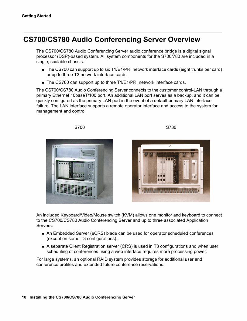
CS700/CS780 Audio Conferencing Server OverviewThe CS700/CS780 Audio Conferencing Server audio conference bridge is a digital signal processor (DSP)-based system. All system components for the S700/780 are included in a single, scalable chassis.
● The CS700 can support up to six T1/E1/PRI network interface cards (eight trunks per card) or up to three T3 network interface cards.
● The CS780 can support up to three T1/E1/PRI network interface cards.
The CS700/CS780 Audio Conferencing Server connects to the customer control-LAN through a primary Ethernet 10baseT/100 port. An additional LAN port serves as a backup, and it can be quickly configured as the primary LAN port in the event of a default primary LAN interface failure. The LAN interface supports a remote operator interface and access to the system for management and control.
An included Keyboard/Video/Mouse switch (KVM) allows one monitor and keyboard to connect to the CS700/CS780 Audio Conferencing Server and up to three associated Application Servers.
● An Embedded Server (eCRS) blade can be used for operator scheduled conferences (except on some T3 configurations).
● A separate Client Registration server (CRS) is used in T3 configurations and when user scheduling of conferences using a web interface requires more processing power.
For large systems, an optional RAID system provides storage for additional user and conference profiles and extended future conference reservations.
S700 S780
CS700/CS780 Audio Conferencing Server Overview
Issue 1 November 2008 11
Minimum Hardware Requirements for S780 SystemsThe minimum hardware requirement for Meeting Exchange 5.1 S780 deployment includes:
1. ZT5550, ZT5550e, or ZT5551 CPU cards
2. NS300 or NS301 DSP cards
3. At least 512 MB CPU Memory
4. At least 40 GB CPU Hard drive
Tip:Tip: You can continue to use your current NIC cards, DSP cards, and S780 system
chassis.
Installation StepsInstallation consists of the following steps:
1. Verify installation of power, thermal management, LAN, and network connections.
2. Verify receipt of necessary hardware and cables.
3. Mount hardware to racks or as specified.
4. Connect power, keyboard/video/mouse, modems, LAN, and network connections.
5. Verify system operation.
6. Notify Support Help Desk that the system is ready to be configured. Note any discrepancies between installed facilities and the Site Survey.
Call Processing ComponentsThe CS700/CS780 Audio Conferencing Server contains Network Interface Cards with T1/E1/ISDN or T3 interfaces, Digital Signal Processors (DSPs), a host CPU, and associated busses and transition cards that enable it to process audio conferences.
The main function of the system hardware is call processing, which occurs as follows:
● A Network Interface Card (NIC): Receives incoming calls from the telephone network and places the calls on a Time Domain Multiplexed (TDM) bus.
● The Time Domain Multiplexed (TMD) bus: Distributes the calls to available DSPs in the system.
● The Digital Signal Processors (DSPs): Perform the operations necessary for calls to participate in a conference, such as analyzing speech and tones and combining speech
Getting Started
12 Installing the CS700/CS780 Audio Conferencing Server
samples. The DSPs then return the processing results, which represent the audio in the conference, back to the TDM bus and then to the NIC card, which transmits the data to the network.
● A Central Processing Unit (CPU): Controls system operation and manages system resources. It assigns DSPs to conferences as they are scheduled, handles incoming calls, and assigns channels on the TDM bus.
● A T3: Can replace one or more network interface cards for higher capacity. The availability of slots for DSP cards limits the system to a maximum of three T3 cards.
● An embedded or separate Client Registration Server (CRS): Provides operator only (eCRS) or operator and user conference scheduling by a web-based interface.
Site Survey
Issue 1 November 2008 13
Site SurveyThe Site Survey is used to determine the exact specifications for the S700/780.
PowerVerify that the equipment delivered matches the power specified in the Site Survey in the following particulars:
● AC or DC power for the S700/780. Also verify that the power is available at the rack or mounting point and that redundant power is available if specified.
● AC or DC power for the Dot Hill RAID (if used). Also verify that the power is available at the rack or mounting point and that redundant power is available if specified.
Network ConnectionsThe Site Survey specifies the characteristics of the network connections. Verify that the patch panel containing the connection points matches the Site Survey in the following particulars:
● All T1/E1/ISDN trunks are available in a convenient location with proper demarcation point equipment. Each trunk must be terminated with RJ45/48C connectors. Note any changes to the information specified on the Site Survey and be sure to report any discrepancies to the Avaya Support Help Desk when reporting the system as “ready for configuration".
● All T3 trunks are available in a convenient location with proper SONET multiplexor or network interface unit as specified. Each T3 must be terminated with a standard BNC connector. Note any changes to the information specified on the Site Survey and be sure to report any discrepancies to the Avaya Support Help Desk when reporting the system as “ready for configuration".
Getting Started
14 Installing the CS700/CS780 Audio Conferencing Server
Modem ConnectionsThe Site Survey specifies the availability of modem connections for the S700/780 and any associated servers. Verify that the telephone lines are available, and that the telephone numbers are correct.
● Each modem should have AC power available.
● Each modem should have a telephone line terminated in RJ11C.
● Verify the telephone number(s). Note any changes to the information specified on the Site Survey, and be sure to report any discrepancies to the Avaya Support Help Desk when reporting the system as “ready for configuration.”
LAN ConnectionsThe Site Survey specifies the availability of LAN connections for the S700/780 and any associated servers. Verify that the connections are available and that the following information specified in the Site Survey is still correct. Note any changes to the information specified on the Site Survey and be sure to report any discrepancies to the Avaya Support Help Desk when reporting the system as “ready for configuration.”
● IP address. (A range is required for server maintenance connections.)
● LAN name of each server.
● Subnet Mask.
● Default Gateway IP address.
● Up to three DNS Server IP addresses.
● Network domain name.
● Domain login.
● Password.
Note:Note: On a redundant failover, the same information is used on the primary or fallback
network. The S700/780 is not dual homed. There should not be additional information that indicates dual homing.
Site Survey
Issue 1 November 2008 15
Analog Audio InterfaceThe Site Survey specifies the availability of analog audio interface input. Verify that the connection is available and presented as RCA plug to front of S700/780. The analog audio interface accepts a maximum signal of 5VPP with input impedance of 20K Ohms.
Getting Started
16 Installing the CS700/CS780 Audio Conferencing Server
UnpackingThe S700/780 ships in several boxes. The first box should have a packing list showing what is included. Verify that all items were shipped and that all have been received.
A list of ordered equipment is included with the Site Survey provided by the Project Manager.
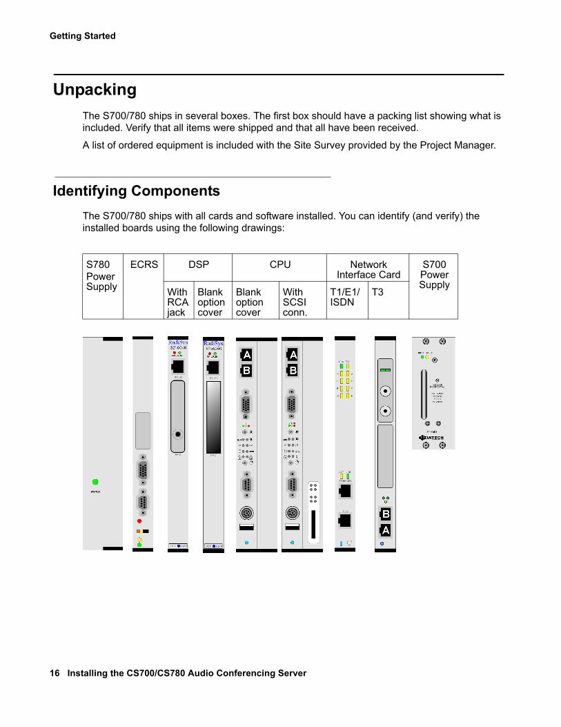
Identifying ComponentsThe S700/780 ships with all cards and software installed. You can identify (and verify) the installed boards using the following drawings:
S780Power Supply
ECRS DSP CPU Network Interface Card
S700 Power Supply
With RCA jack
Blank option cover
Blank option cover
With SCSI conn.
T1/E1/ISDN
T3
Unpacking
Issue 1 November 2008 17
Mounting OptionsThe CS700/CS780 Audio Conferencing Server can be mounted in an IT-style rack (front/rear mount) or a telco-style rack (center mount).
Rack Mount
The system fits standard 19-inch racks. Mounting flanges attached to the side of the CS700 cabinet can be reversed for 19-inch or 23-inch racks. The CS780 requires special mounts for 23-inch racks.
There are mounting points on the side of the cabinet at the front and at the center so that the cabinet can be used in IT-style (front/rear mount) or telco-style (center mount) racks.
● The CS700 chassis is 16.22-inch (655.5mm) high and mounts in 15U.
● The CS780 chassis is 13.97-inch (355mm) high and mounts in 8U.
Other chassis dimensions are as follows:
● 17.42-inch (442.1 mm) wide, without the rack mounting
● 13.3-inch (337.8mm) deep, not including injector/ejector hardware
● Minimum of 8-inch clearance required in the front and rear.
Power OptionsThe CS700/CS780 Audio Conferencing Server is available in AC power input and DC power input versions. For AC-powered systems, an uninterruptible power supply (UPS) is recommended to prevent system shutdown and loss of data during power interruptions.
Getting Started
18 Installing the CS700/CS780 Audio Conferencing Server
Environmental RequirementsVerify that the customer-provided operating conditions, power, and cooling requirements have been met.
Operating Conditions● Ambient temperature, operating: 5°C to + 40°C (32-104°F)
● Ambient temperature, storage: -40°C to +70°C
● Relative humidity, operating: 5% to 95%, non-condensing at 40°C
● Non-operating shock: 30 g for 6 ms
● Operating shock: 15 g for 11 ms
● Non-operating vibration: 5 to 20 Hz at 0.35mm (5 g) (for the chassis alone, final numbers will be less)
● Operating vibration: 5 to 200 Hz at 0.35mm (5 g) (for the chassis alone, final numbers will be less)
Environmental Requirements
Issue 1 November 2008 19
Power and Cooling RequirementsThe following sections describe the thermal and power requirements for each platform.
CS700 Platform
The CS700 can be configured with up to four power supplies that work in tandem to provide a total of 600W output with N+1 redundancy. The supplies are accessible from the front of the unit and may be hot swapped.
Thermal DissipationThe thermal dissipation for the CS700 Platform is less than 1130 BTU per hour.
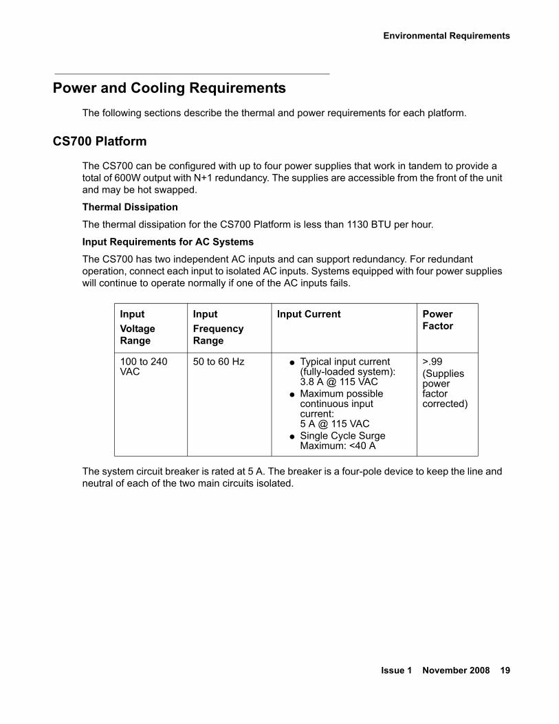
Input Requirements for AC SystemsThe CS700 has two independent AC inputs and can support redundancy. For redundant operation, connect each input to isolated AC inputs. Systems equipped with four power supplies will continue to operate normally if one of the AC inputs fails.
The system circuit breaker is rated at 5 A. The breaker is a four-pole device to keep the line and neutral of each of the two main circuits isolated.
Input Voltage Range
InputFrequency Range
Input Current Power Factor
100 to 240 VAC
50 to 60 Hz ● Typical input current (fully-loaded system): 3.8 A @ 115 VAC
● Maximum possible continuous input current: 5 A @ 115 VAC
● Single Cycle Surge Maximum: <40 A
>.99 (Supplies power factor corrected)
Getting Started
20 Installing the CS700/CS780 Audio Conferencing Server
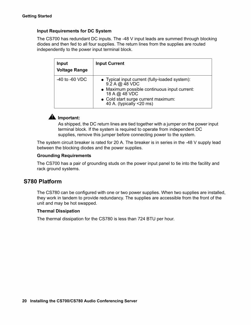
Input Requirements for DC SystemThe CS700 has redundant DC inputs. The -48 V input leads are summed through blocking diodes and then fed to all four supplies. The return lines from the supplies are routed independently to the power input terminal block.
! Important:Important: As shipped, the DC return lines are tied together with a jumper on the power input
terminal block. If the system is required to operate from independent DC supplies, remove this jumper before connecting power to the system.
The system circuit breaker is rated for 20 A. The breaker is in series in the -48 V supply lead between the blocking diodes and the power supplies.
Grounding RequirementsThe CS700 has a pair of grounding studs on the power input panel to tie into the facility and rack ground systems.
S780 Platform
The CS780 can be configured with one or two power supplies. When two supplies are installed, they work in tandem to provide redundancy. The supplies are accessible from the front of the unit and may be hot swapped.
Thermal DissipationThe thermal dissipation for the CS780 is less than 724 BTU per hour.
Input Voltage Range
Input Current
-40 to -60 VDC ● Typical input current (fully-loaded system): 9.2 A @ 48 VDC
● Maximum possible continuous input current: 18 A @ 48 VDC
● Cold start surge current maximum: 40 A. (typically <20 ms)
Environmental Requirements
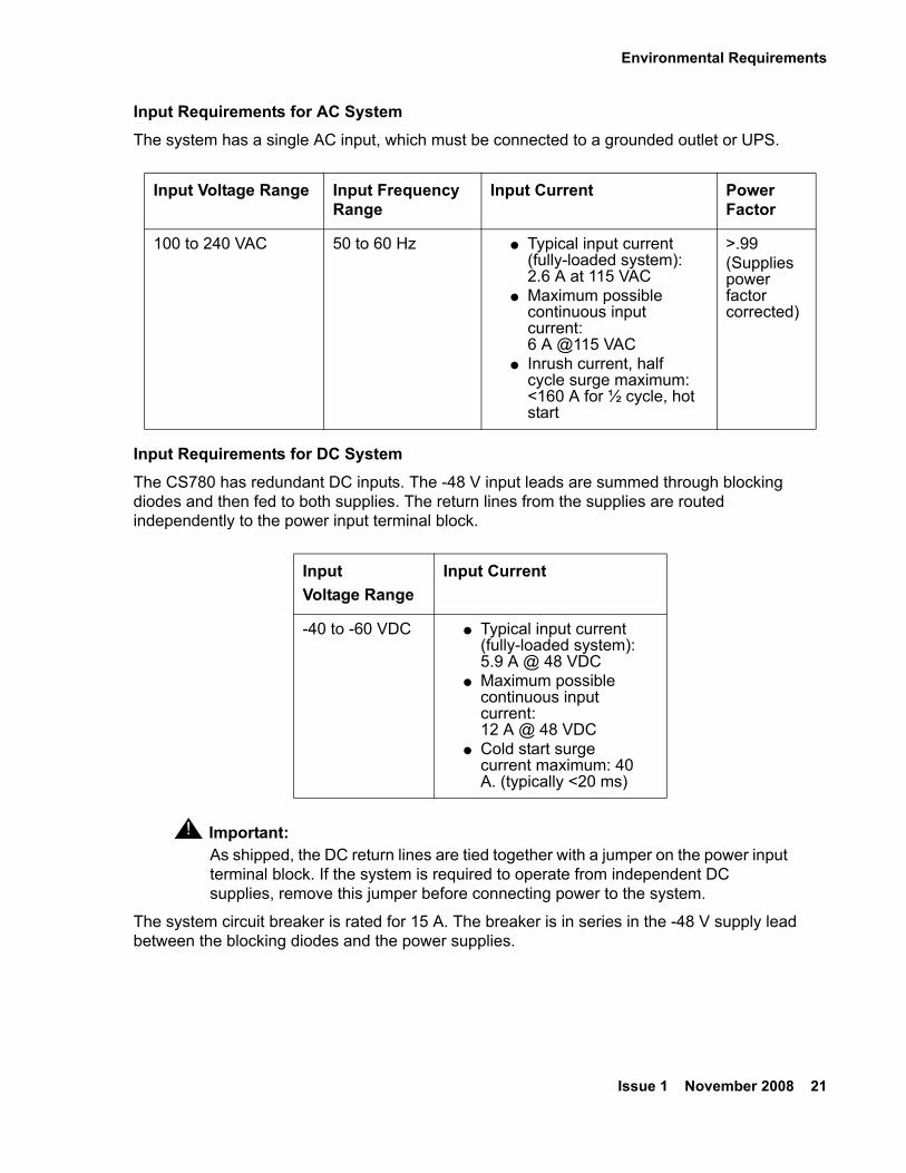
Issue 1 November 2008 21
Input Requirements for AC SystemThe system has a single AC input, which must be connected to a grounded outlet or UPS.
Input Requirements for DC SystemThe CS780 has redundant DC inputs. The -48 V input leads are summed through blocking diodes and then fed to both supplies. The return lines from the supplies are routed independently to the power input terminal block.
! Important:Important: As shipped, the DC return lines are tied together with a jumper on the power input
terminal block. If the system is required to operate from independent DC supplies, remove this jumper before connecting power to the system.
The system circuit breaker is rated for 15 A. The breaker is in series in the -48 V supply lead between the blocking diodes and the power supplies.
Input Voltage Range Input Frequency Range
Input Current Power Factor
100 to 240 VAC 50 to 60 Hz ● Typical input current (fully-loaded system): 2.6 A at 115 VAC
● Maximum possible continuous input current: 6 A @115 VAC
● Inrush current, half cycle surge maximum: <160 A for ½ cycle, hot start
>.99 (Supplies power factor corrected)
Input Voltage Range
Input Current
-40 to -60 VDC ● Typical input current (fully-loaded system): 5.9 A @ 48 VDC
● Maximum possible continuous input current: 12 A @ 48 VDC
● Cold start surge current maximum: 40 A. (typically <20 ms)
Getting Started
22 Installing the CS700/CS780 Audio Conferencing Server
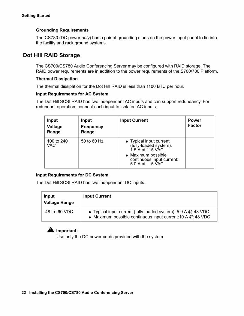
Grounding RequirementsThe CS780 (DC power only) has a pair of grounding studs on the power input panel to tie into the facility and rack ground systems.
Dot Hill RAID Storage
The CS700/CS780 Audio Conferencing Server may be configured with RAID storage. The RAID power requirements are in addition to the power requirements of the S700/780 Platform.
Thermal DissipationThe thermal dissipation for the Dot Hill RAID is less than 1100 BTU per hour.
Input Requirements for AC SystemThe Dot Hill SCSI RAID has two independent AC inputs and can support redundancy. For redundant operation, connect each input to isolated AC inputs.
Input Requirements for DC SystemThe Dot Hill SCSI RAID has two independent DC inputs.
! Important:Important: Use only the DC power cords provided with the system.
Input Voltage Range
InputFrequency Range
Input Current Power Factor
100 to 240 VAC
50 to 60 Hz ● Typical input current (fully-loaded system): 1.5 A at 115 VAC
● Maximum possible continuous input current:5.0 A at 115 VAC
Input Voltage Range
Input Current
-48 to -60 VDC ● Typical input current (fully-loaded system): 5.9 A @ 48 VDC● Maximum possible continuous input current:10 A @ 48 VDC
Environmental Requirements
Issue 1 November 2008 23
Separate Client Registration/Web Portal/Web Conferencing Servers
Separate Client Registration Servers, Web Portal Servers, and Web Conferencing Servers are off-the-shelf servers from Dell or IBM. The following models are certified by Avaya:
● Dell™ PowerEdge™ 1950 (1U)
● IBM xSeries 336X (1U)
Customers may also provide their own server running Microsoft Windows 2003 Server, SP2 or Microsoft SQL Server 2005 SP2.
Thermal ManagementPlease refer to the Site Survey or documentation for the appropriate server for this information.
AC System Power RequirementsPlease refer to the Site Survey or documentation for the appropriate server for this information.
DC System Power RequirementsDC power is not available for separate servers.
Desktop clients
Microsoft Desktop Client
● Windows XP (SP2)
● Vista Business
Browsers
● Internet Explorer 6 & 7
● Firefox 2.0
Maintenance ModemA direct-dial phone line must be dedicated to each maintenance modem. A regular phone line should be used. The maintenance modems enable Avaya personnel to dial into the system directly for remote support such as running diagnostics, troubleshooting, and updating software.
Conference Server Maintenance Modem
The Conference Server uses a Multi-Tech modem. A special cable is supplied to connect the the mini-DB9 COM2 connector on the rear of the CPU (CPU transition card). The COM1 connector on the front or back of the CPU cannot be used for the maintenance modem.
Getting Started
24 Installing the CS700/CS780 Audio Conferencing Server
Server Maintenance Modems
Other servers use a US Robotics (USR) modem with a standard DB9 cable.
LAN Cabling
Issue 1 November 2008 25
LAN CablingThe CS700/CS780 Audio Conferencing Server LAN interface connects to an Ethernet network by up to 100 meters of Category 5 or 5e cable.
The network should be partitioned to keep average network traffic levels to 60% utilization or less. Additionally, the LAN cabling must comply with all national codes.
Keep cable runs between systems and concentrators short and reasonably clear of electrical noise sources such as motors and fluorescent lighting. The specifications for the amount of disturbance that can be introduced into the link between the system and the concentrator are defined in the 8802.3 standard. The link including all connectors and patch cables must meet these specifications.
You can measure compliance directly by using cable testers from third parties specifically designed for qualifying 10/100 Base-T links. These testers verify the physical characteristics of the cable and connectors and can perform the tests for noise specified in the 8802.3 standard to verify that the link can provide reliable operation.
! CAUTION:CAUTION: Do not use “Silver Satin” cable for any portion of the link. It does not meet the
requirements for 10BaseT transmission.
See the following technical references if further wiring information is required:
● EIA/TIA 568 (Standard for structured premises wiring in North America.)
● ISO/IEC DIS11801 (Draft international standard for building wiring.)
The Avaya CS700/ 780 Platforms supports redundant failover networks.
Note:Note: The Avaya CS700/ 780 Platforms uses the same identity on both the primary and
fallback networks, so it cannot be dual homed.
T3 System LAN CablingT3 systems include a Netgear 5-port hub used to connect the CS700/CS780 Audio Conferencing Server to the T3 cards. The customer LAN connects to the Netgear hub instead of directly to the CS700/CS780 Audio Conferencing Server. (The T3 cards download their operating system from the CS700/CS780 Audio Conferencing Server. The private hub allows faster downloads than routing through the customer LAN.)
Getting Started
26 Installing the CS700/CS780 Audio Conferencing Server
Network Cabling
T1/E1/ISDN Network CablingT1/E1/ISDN network cabling is shielded twisted pair (one pair transmit, one pair receive). If the cable is continuous to the CSU, PBX, or channel bank, the shield must be grounded to the frame ground at that end. If there is a DSX or other break in the cable, the shield must be connected to the shield of the other cable. The maximum cable length is 655 feet. A CSU may be used to drive signals greater distances.
A CSU is required for T1 or T1 ISDN connection to public telephone networks.
The local phone company can recommend or rent a CSU to the customer. Many kinds of CSUs are available. The CSU selected must include:
● Remote loopbacks for testing repeated T1 lines from the telephone office
● Terminating repeater power (up to ±130 Vdc)
● Alarming
● Provision for an all 1s signal to the T1 lines, if the conference system is serviced (also called blue signal or keep alive signal)
Customers have additional requirements if they need a system to connect to more than one telephone network. The system can be configured to synch to the first T1. Since there may be large accumulated jitter at the end points of two T1 networks, the CSUs in these cases require large buffers to attenuate the jitter between networks. Without adequate jitter attenuation, excessive frame slips will occur. Avaya recommends the customer discuss these requirements with the network provider.
If possible, network connections should be terminated in a main distribution frame located at the top of the rack containing the S700/780 Conference Bridge.
T3 Network CablingT3 network cabling is coaxial cable (one cable transmit, one cable receive) terminated in BNC connectors.
If possible, network connections should be terminated in a main distribution frame located at the top of the rack containing the S700/780 Conference Bridge.
Issue 1 November 2008 27
Chapter 2: Installing S700/780 Hardware
This chapter describes hardware installation procedures.
Installation consists of the following steps:
1. Verify installation of power, thermal management, LAN, and network connections.
2. Verify receipt of necessary hardware and cables.
3. Mount hardware to racks as specified.
4. Connect power, keyboard/video/mouse, modems, LAN, and network connections.
5. Verify system operation.
6. Notify Support Help Desk that the system is ready to be configured. Note any discrepancies between installed facilities and the Site Survey.
Steps 1 and 2 were covered in “Chapter 1: Getting Started.” This chapter covers steps 3 through 6.
Before You BeginYou should have a working knowledge of teleconferencing concepts, customer requirements, telecommunication protocols (TCP/IP, VOIP/SIP), and UNIX commands.
Electrostatic Discharge (ESD) PrecautionsIf the replacement of any system board is required, you must adhere to industry-standard ESD precautions.
When repairing equipment in the field, the minimum equipment necessary for ESD protection is:
● Anti-static conductive mat with grounding cable.
● Wrist strap with grounding cable.
● ESD protective storage bags or other suitable containers.
Installing S700/780 Hardware
28 Installing the CS700/CS780 Audio Conferencing Server
Site RequirementsBefore beginning installation, verify the information on the Site Survey as described in Chapter 1: Getting Started.
UnpackingBefore beginning installation, identify and inventory all equipment received, and verify that all needed items are available as described in Chapter 1: Getting Started.
Tools and MaterialsThe following tools and materials are required to perform the installation:
● Phillips and flat screwdrivers.
● ESD wrist strap.
● Tie wraps and labeler.
● Crimpers, pliers, RJ45 plugs, and RJ11 plugs.
● Category 5 or 5E cable.
● Fixed (socket) or adjustable wrenches.
● LAN cables.
● Power cords.
● Mouse and keyboard cables.
Installing the S700/780 Chassis
Issue 1 November 2008 29
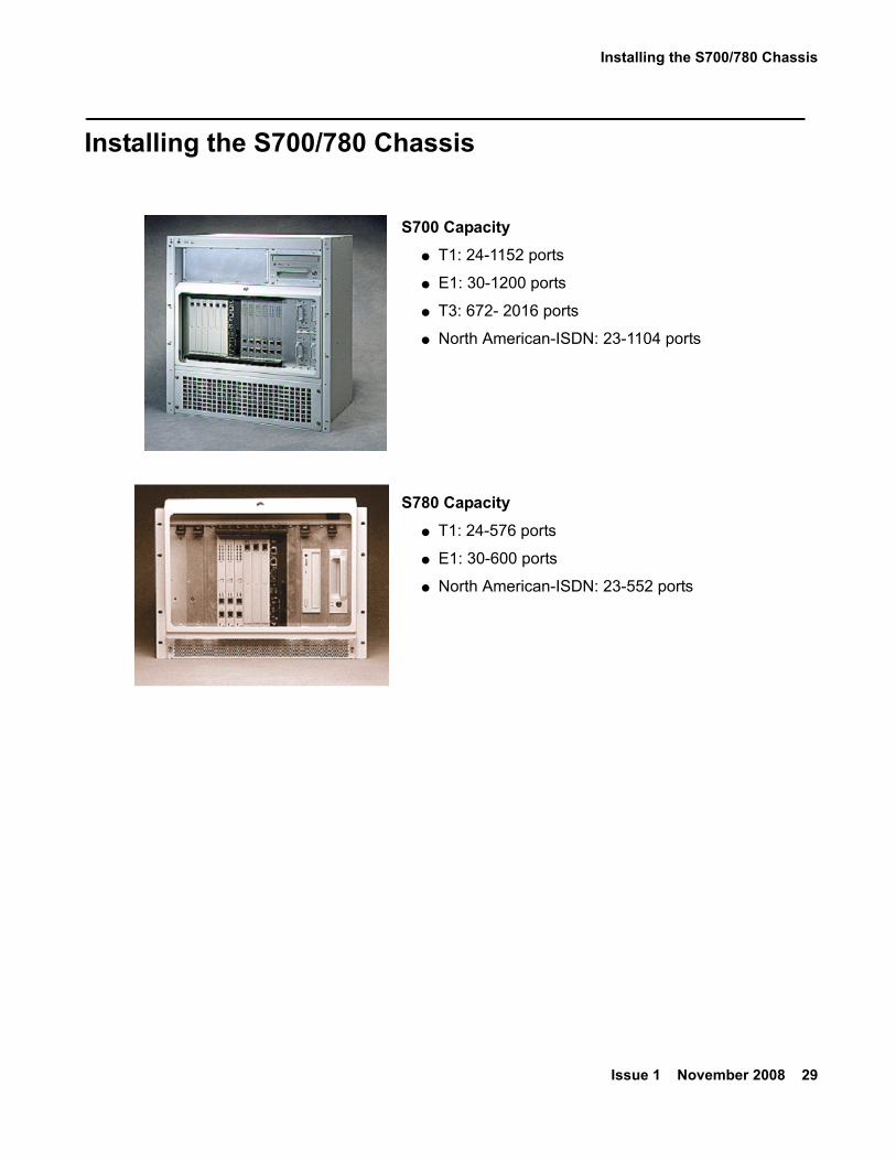
Installing the S700/780 Chassis
S700 Capacity● T1: 24-1152 ports
● E1: 30-1200 ports
● T3: 672- 2016 ports
● North American-ISDN: 23-1104 ports
S780 Capacity● T1: 24-576 ports
● E1: 30-600 ports
● North American-ISDN: 23-552 ports
Installing S700/780 Hardware
30 Installing the CS700/CS780 Audio Conferencing Server
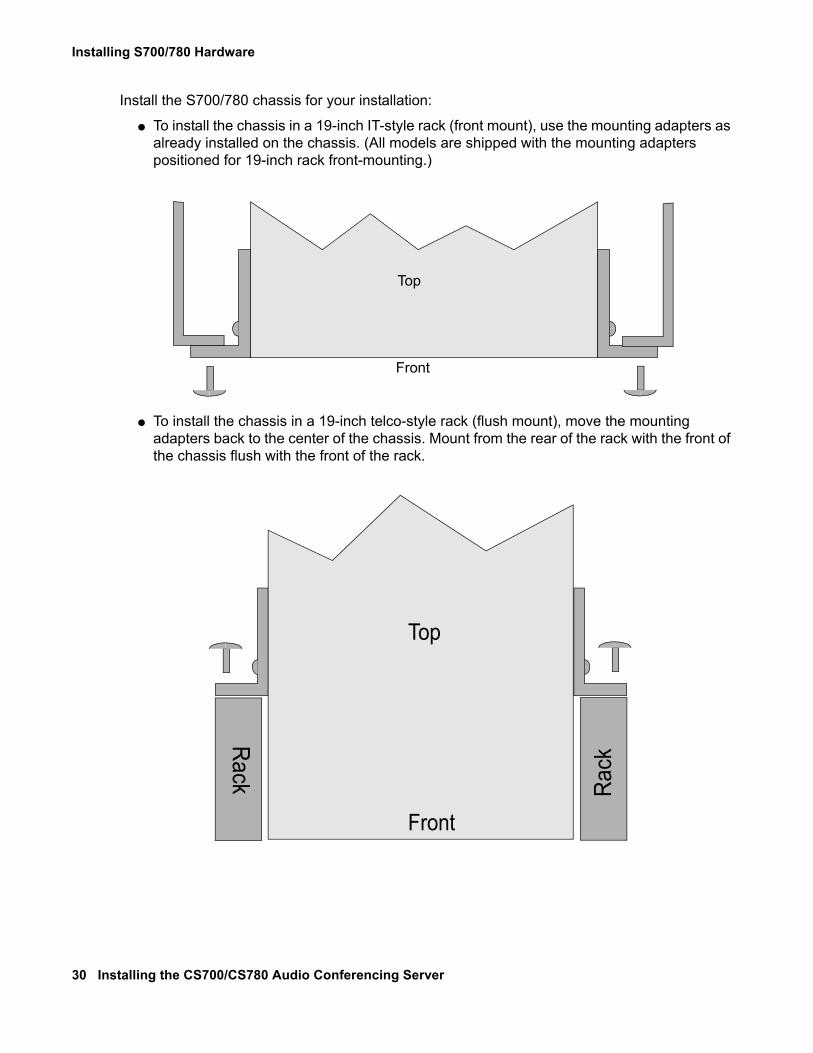
Install the S700/780 chassis for your installation:
● To install the chassis in a 19-inch IT-style rack (front mount), use the mounting adapters as already installed on the chassis. (All models are shipped with the mounting adapters positioned for 19-inch rack front-mounting.)
● To install the chassis in a 19-inch telco-style rack (flush mount), move the mounting adapters back to the center of the chassis. Mount from the rear of the rack with the front of the chassis flush with the front of the rack.
Front
Top
Front
TopRa
ckRack
Installing the S700/780 Chassis
Issue 1 November 2008 31
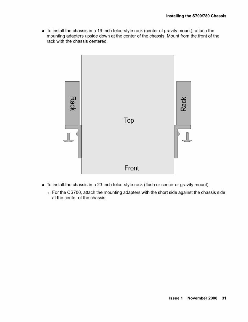
● To install the chassis in a 19-inch telco-style rack (center of gravity mount), attach the mounting adapters upside down at the center of the chassis. Mount from the front of the rack with the chassis centered.
● To install the chassis in a 23-inch telco-style rack (flush or center or gravity mount):
l For the CS700, attach the mounting adapters with the short side against the chassis side at the center of the chassis.
Front
Top
Rack
Rack
Installing S700/780 Hardware
32 Installing the CS700/CS780 Audio Conferencing Server
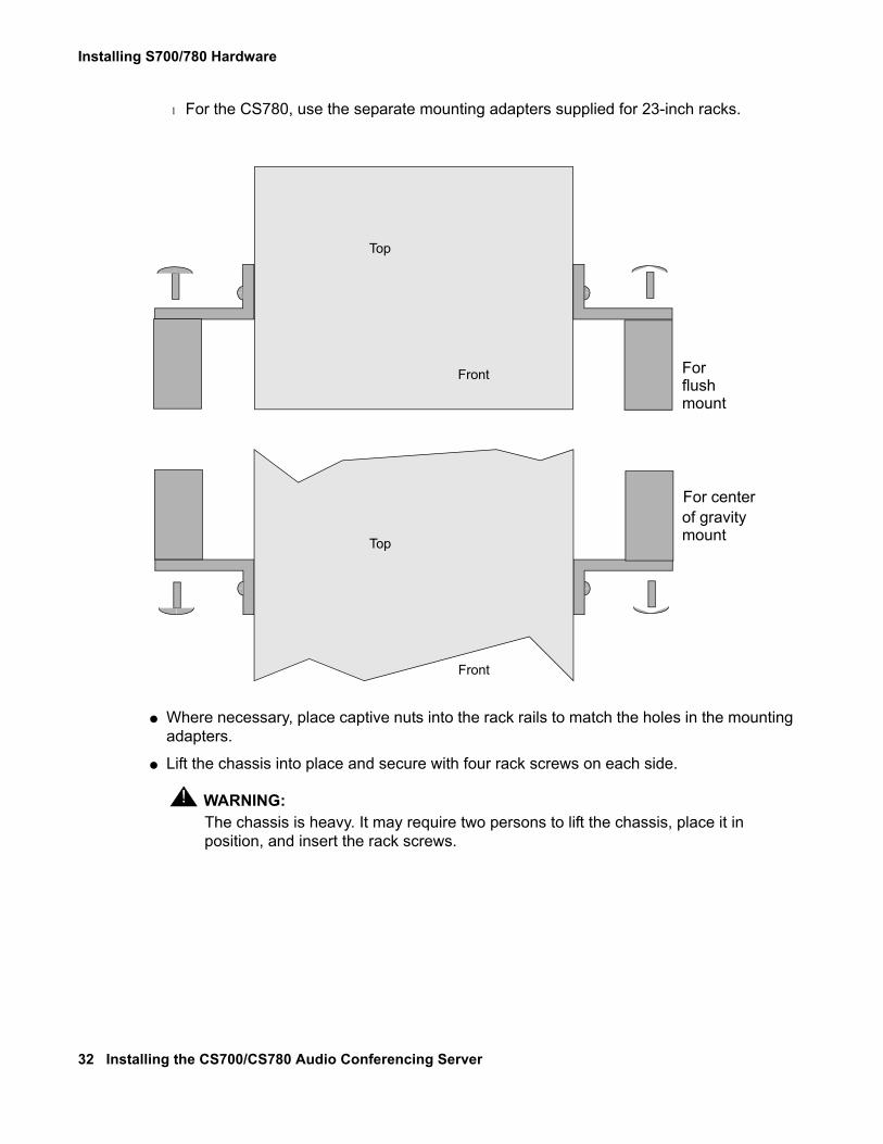
l For the CS780, use the separate mounting adapters supplied for 23-inch racks.
● Where necessary, place captive nuts into the rack rails to match the holes in the mounting adapters.
● Lift the chassis into place and secure with four rack screws on each side.
! WARNING:WARNING: The chassis is heavy. It may require two persons to lift the chassis, place it in
position, and insert the rack screws.
Front
Top
Front
Top
For flush mount
For centerof gravitymount
Installing the S700/780 Chassis
Issue 1 November 2008 33
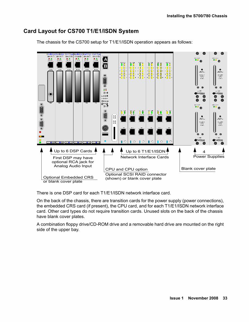
Card Layout for CS700 T1/E1/ISDN System
The chassis for the CS700 setup for T1/E1/ISDN operation appears as follows:
There is one DSP card for each T1/E1/ISDN network interface card.
On the back of the chassis, there are transition cards for the power supply (power connections), the embedded CRS card (if present), the CPU card, and for each T1/E1/ISDN network interface card. Other card types do not require transition cards. Unused slots on the back of the chassis have blank cover plates.
A combination floppy drive/CD-ROM drive and a removable hard drive are mounted on the right side of the upper bay.
Up to 6 T1/E1/ISDNUp to 6 DSP Cards
First DSP may haveoptional RCA jack forAnalog Audio Input
4Power Supplies
Optional Embedded CRSor blank cover plate
Network Interface Cards
CPU and CPU optionOptional SCSI RAID connector(shown) or blank cover plate
Blank cover plate
Installing S700/780 Hardware
34 Installing the CS700/CS780 Audio Conferencing Server
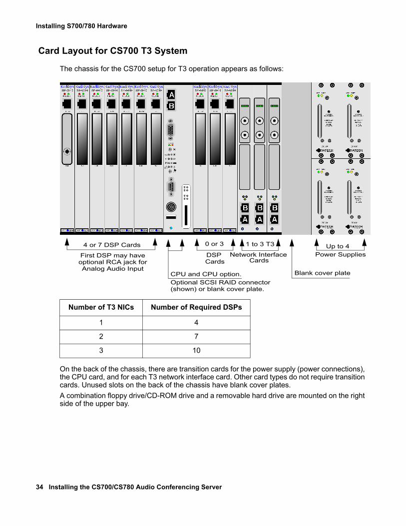
Card Layout for CS700 T3 System
The chassis for the CS700 setup for T3 operation appears as follows:
On the back of the chassis, there are transition cards for the power supply (power connections), the CPU card, and for each T3 network interface card. Other card types do not require transition cards. Unused slots on the back of the chassis have blank cover plates.A combination floppy drive/CD-ROM drive and a removable hard drive are mounted on the right side of the upper bay.
Number of T3 NICs Number of Required DSPs
1 4
2 7
3 10
1 to 3 T34 or 7 DSP Cards
First DSP may haveoptional RCA jack forAnalog Audio Input
Up to 4Power SuppliesNetwork Interface
CPU and CPU option.Optional SCSI RAID connector(shown) or blank cover plate.
Blank cover plate
Cards
0 or 3
DSP Cards
Installing the S700/780 Chassis
Issue 1 November 2008 35
Other CS700 Configurations
Combinations of T1/E1/ISDN and T3 are possible. Combination system layouts are not shown.
● Systems with one or two T3 cards may have an embedded CRS in the left-most slot.
● Systems with one or two T3 cards may have one or more T1/E1/PRI cards.
● NICs are inserted right to left starting after the two unit blank filler plate next to the power supplies and proceeding leftward. The T3 NICs must come before (to the right of) any T1/E1/PRI NICs.
● DSPs are inserted left to right starting at the left side of the chassis. Up to seven DSPs are inserted to the left of the CPU, and up to three more are inserted to the right of the CPU as needed.
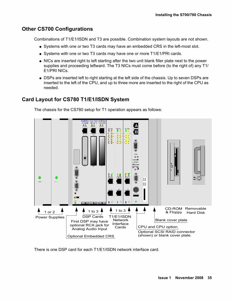
Card Layout for CS780 T1/E1/ISDN System
The chassis for the CS780 setup for T1 operation appears as follows:
There is one DSP card for each T1/E1/ISDN network interface card.
1 to 3
DSP CardsFirst DSP may haveoptional RCA jack forAnalog Audio Input
1 or 2Power Supplies
Network
CPU and CPU option.Optional SCSI RAID connector(shown) or blank cover plate.
Blank cover plate
CardsInterface
T1/E1/ISDN
CD-ROM& Floppy
RemovableHard Disk1 to 3
Optional Embedded CRS
Installing S700/780 Hardware
36 Installing the CS700/CS780 Audio Conferencing Server
On the back of the chassis, there are transition cards for the power supply (power connections), the embedded CRS card (if present), the CPU card, and for each T1/E1/ISDN network interface cards. Other card types do not require transition cards. Unused slots on the back of the chassis have blank cover plates.
A combination floppy drive/CD-ROM drive and a removable hard drive are mounted on the right side of the system.
Installing the Dot Hill RAID ChassisThe Dot Hill RAID chassis can be installed in an IT-style rack (with front and rear mounting rails) or in a telco-style rack.
! Important:Important: The Dot Hill RAID must be installed close enough to the S700/780 so that the
six-foot cables can reach from the SCSI connector on the back of the RAID to the SCSI connector on the front of the S700/780.
Installing the Dot Hill RAID Chassis
Issue 1 November 2008 37
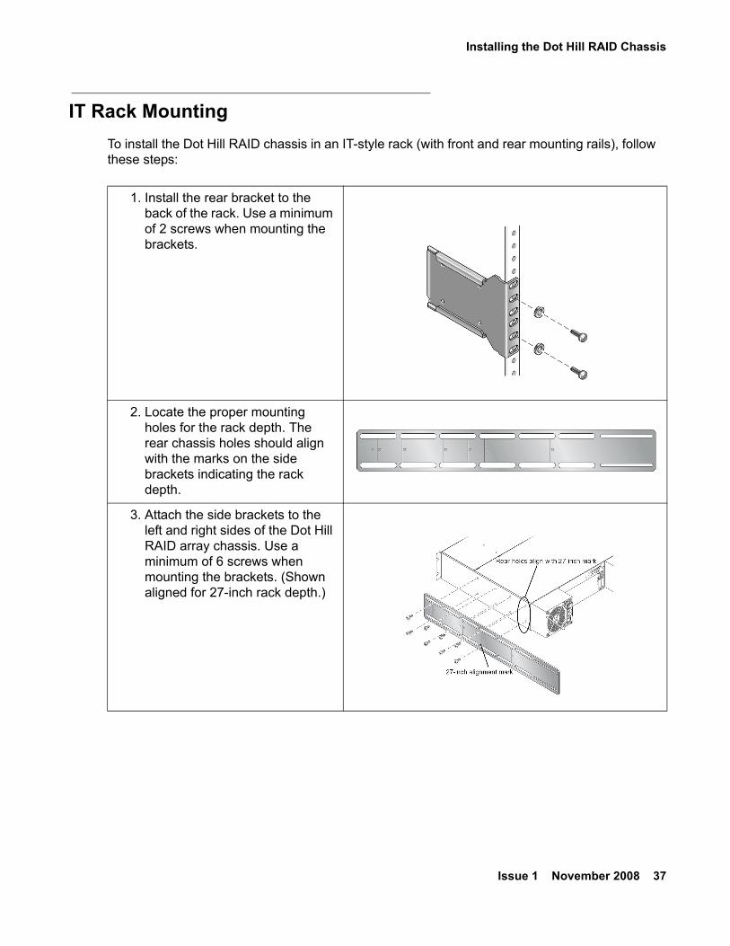
IT Rack MountingTo install the Dot Hill RAID chassis in an IT-style rack (with front and rear mounting rails), follow these steps:
1. Install the rear bracket to the back of the rack. Use a minimum of 2 screws when mounting the brackets.
2. Locate the proper mounting holes for the rack depth. The rear chassis holes should align with the marks on the side brackets indicating the rack depth.
3. Attach the side brackets to the left and right sides of the Dot Hill RAID array chassis. Use a minimum of 6 screws when mounting the brackets. (Shown aligned for 27-inch rack depth.)
Installing S700/780 Hardware
38 Installing the CS700/CS780 Audio Conferencing Server
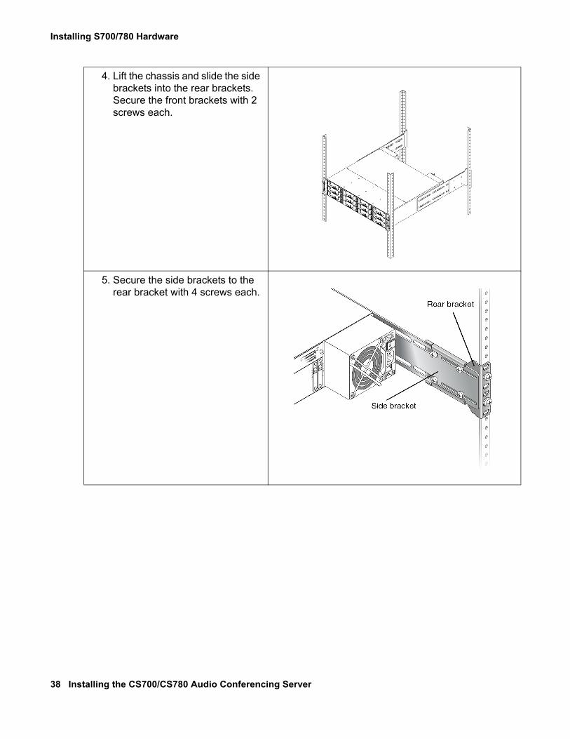
4. Lift the chassis and slide the side brackets into the rear brackets. Secure the front brackets with 2 screws each.
5. Secure the side brackets to the rear bracket with 4 screws each.
Installing the Dot Hill RAID Chassis
Issue 1 November 2008 39
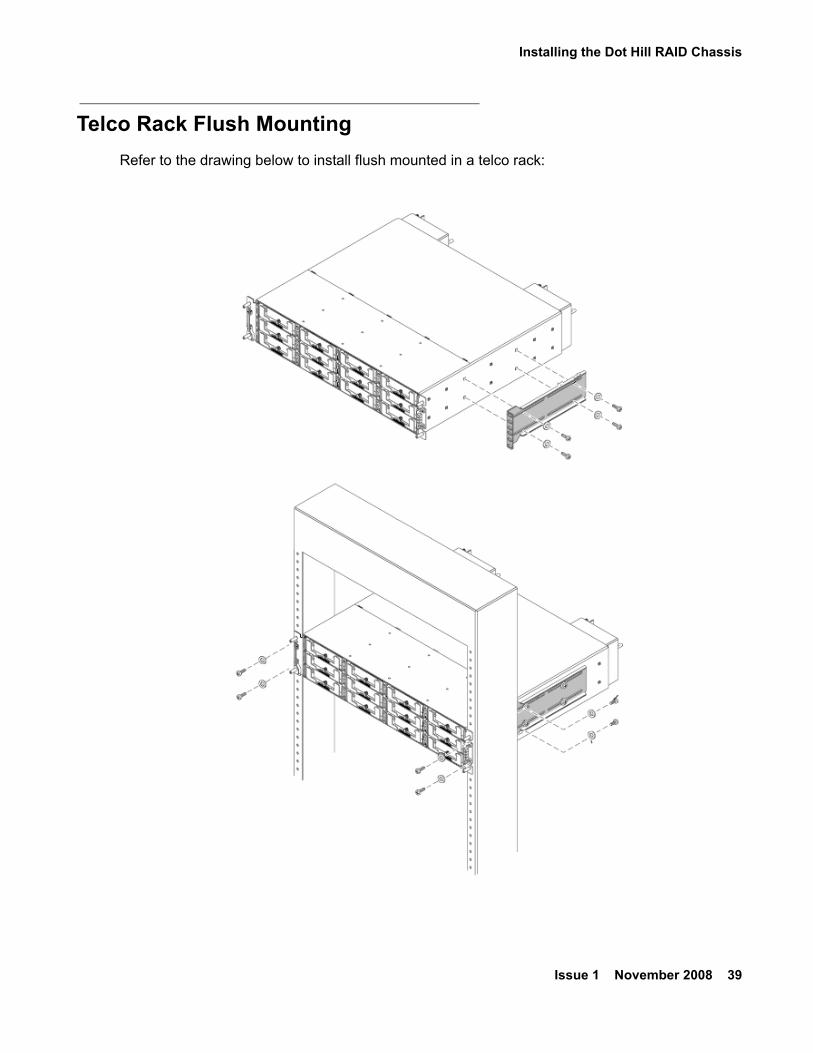
Telco Rack Flush MountingRefer to the drawing below to install flush mounted in a telco rack:
Installing S700/780 Hardware
40 Installing the CS700/CS780 Audio Conferencing Server
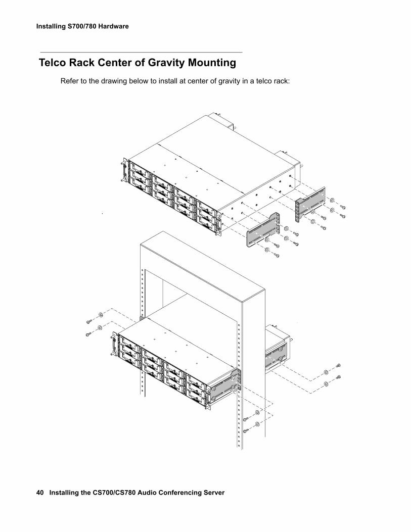
Telco Rack Center of Gravity MountingRefer to the drawing below to install at center of gravity in a telco rack:
Installing the KVM Switch and Application Servers
Issue 1 November 2008 41
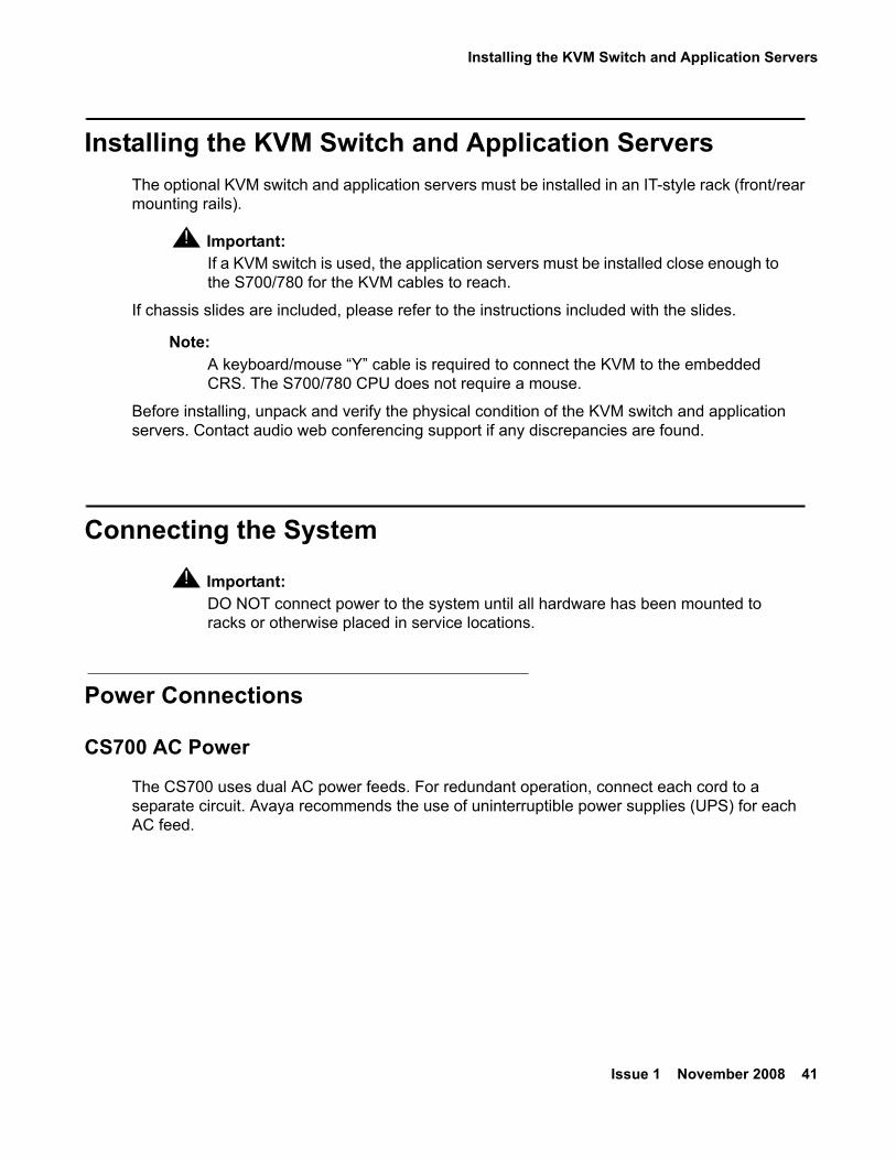
Installing the KVM Switch and Application ServersThe optional KVM switch and application servers must be installed in an IT-style rack (front/rear mounting rails).
! Important:Important: If a KVM switch is used, the application servers must be installed close enough to
the S700/780 for the KVM cables to reach.
If chassis slides are included, please refer to the instructions included with the slides.
Note:Note: A keyboard/mouse “Y” cable is required to connect the KVM to the embedded
CRS. The S700/780 CPU does not require a mouse.
Before installing, unpack and verify the physical condition of the KVM switch and application servers. Contact audio web conferencing support if any discrepancies are found.
Connecting the System! Important:
Important: DO NOT connect power to the system until all hardware has been mounted to racks or otherwise placed in service locations.
Power Connections
CS700 AC Power
The CS700 uses dual AC power feeds. For redundant operation, connect each cord to a separate circuit. Avaya recommends the use of uninterruptible power supplies (UPS) for each AC feed.
Installing S700/780 Hardware
42 Installing the CS700/CS780 Audio Conferencing Server
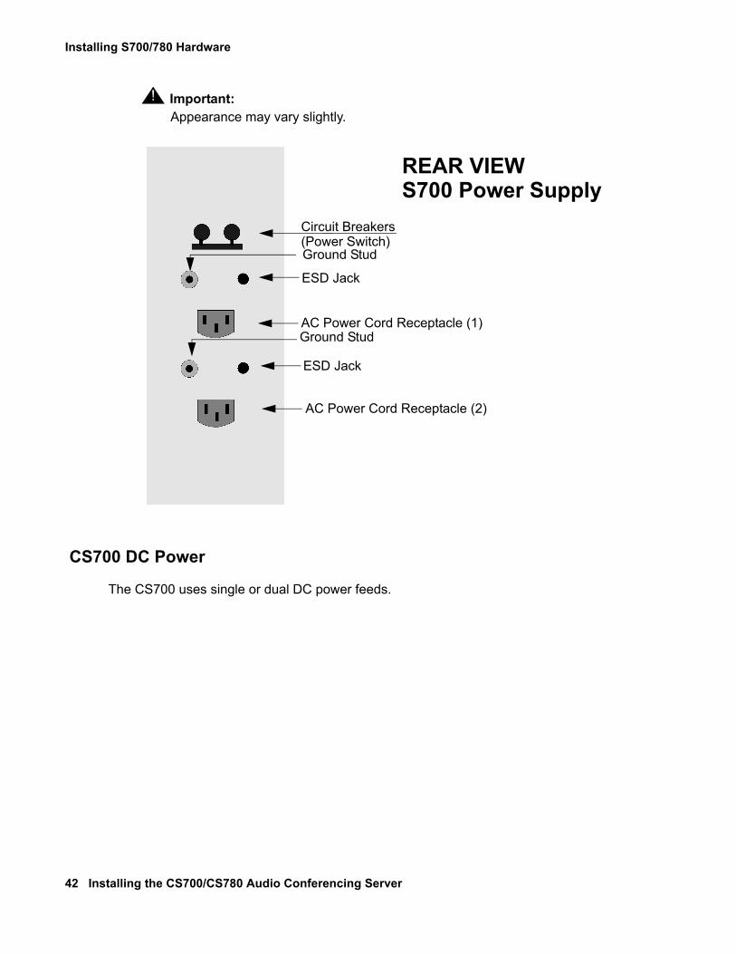
! Important:Important: Appearance may vary slightly.
CS700 DC Power
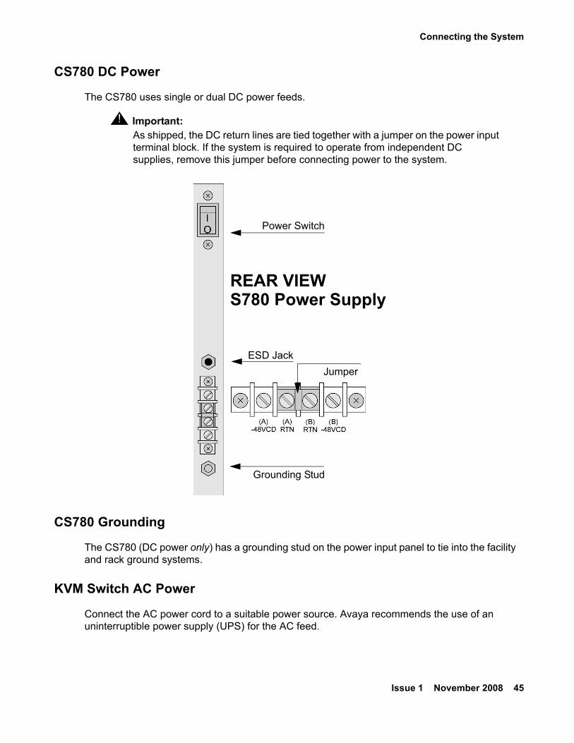
The CS700 uses single or dual DC power feeds.
Circuit Breakers(Power Switch)Ground Stud
ESD Jack
AC Power Cord Receptacle (1)Ground Stud
ESD Jack
AC Power Cord Receptacle (2)
REAR VIEWS700 Power Supply
Connecting the System
Issue 1 November 2008 43
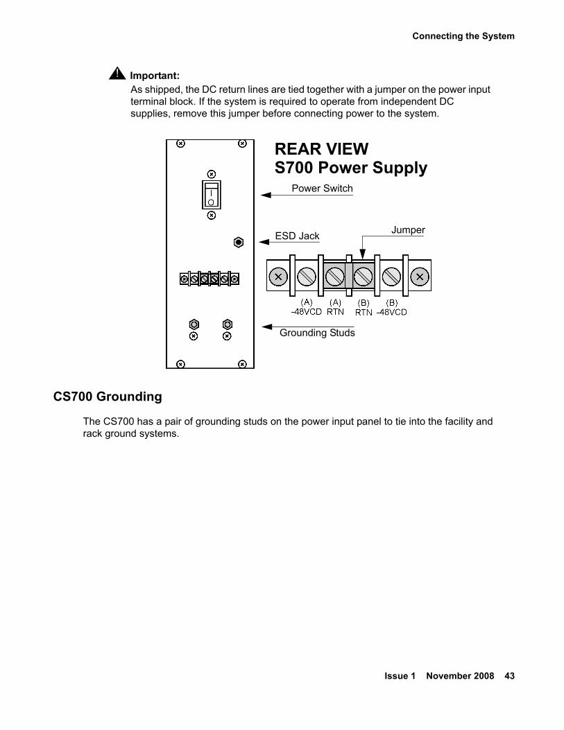
! Important:Important: As shipped, the DC return lines are tied together with a jumper on the power input
terminal block. If the system is required to operate from independent DC supplies, remove this jumper before connecting power to the system.
CS700 Grounding
The CS700 has a pair of grounding studs on the power input panel to tie into the facility and rack ground systems.
ESD Jack
Grounding Studs
Power Switch
Jumper
REAR VIEWS700 Power Supply
Installing S700/780 Hardware
44 Installing the CS700/CS780 Audio Conferencing Server
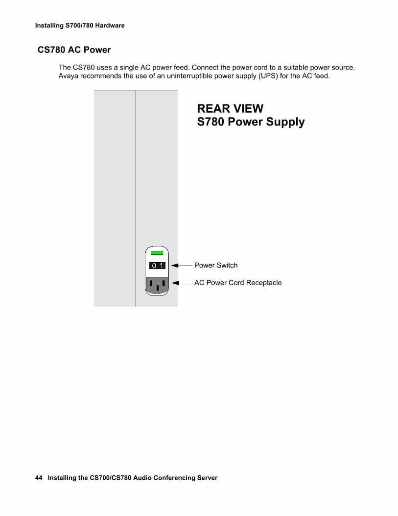
CS780 AC Power
The CS780 uses a single AC power feed. Connect the power cord to a suitable power source. Avaya recommends the use of an uninterruptible power supply (UPS) for the AC feed.
Power Switch
AC Power Cord Receptacle
REAR VIEWS780 Power Supply
Connecting the System
Issue 1 November 2008 45
CS780 DC Power
The CS780 uses single or dual DC power feeds.
! Important:Important: As shipped, the DC return lines are tied together with a jumper on the power input
terminal block. If the system is required to operate from independent DC supplies, remove this jumper before connecting power to the system.
CS780 Grounding
The CS780 (DC power only) has a grounding stud on the power input panel to tie into the facility and rack ground systems.
KVM Switch AC Power
Connect the AC power cord to a suitable power source. Avaya recommends the use of an uninterruptible power supply (UPS) for the AC feed.
REAR VIEWS780 Power Supply
ESD Jack
Grounding Stud
Power Switch
Jumper
Installing S700/780 Hardware
46 Installing the CS700/CS780 Audio Conferencing Server
Dot Hill RAID AC Power
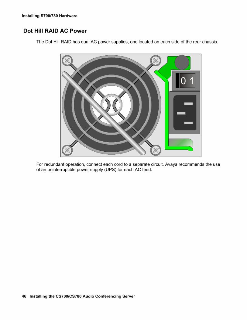
The Dot Hill RAID has dual AC power supplies, one located on each side of the rear chassis.
For redundant operation, connect each cord to a separate circuit. Avaya recommends the use of an uninterruptible power supply (UPS) for each AC feed.
0 1
Connecting the System
Issue 1 November 2008 47
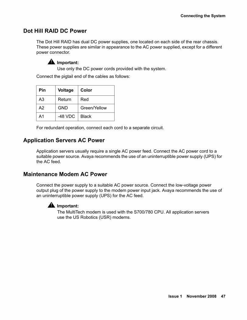
Dot Hill RAID DC Power
The Dot Hill RAID has dual DC power supplies, one located on each side of the rear chassis. These power supplies are similar in appearance to the AC power supplied, except for a different power connector.
! Important:Important: Use only the DC power cords provided with the system.
Connect the pigtail end of the cables as follows:
For redundant operation, connect each cord to a separate circuit.
Application Servers AC Power
Application servers usually require a single AC power feed. Connect the AC power cord to a suitable power source. Avaya recommends the use of an uninterruptible power supply (UPS) for the AC feed.
Maintenance Modem AC Power
Connect the power supply to a suitable AC power source. Connect the low-voltage power output plug of the power supply to the modem power input jack. Avaya recommends the use of an uninterruptible power supply (UPS) for the AC feed.
! Important:Important: The MultiTech modem is used with the S700/780 CPU. All application servers
use the US Robotics (USR) modems.
Pin Voltage Color
A3 Return Red
A2 GND Green/Yellow
A1 -48 VDC Black
Installing S700/780 Hardware
48 Installing the CS700/CS780 Audio Conferencing Server
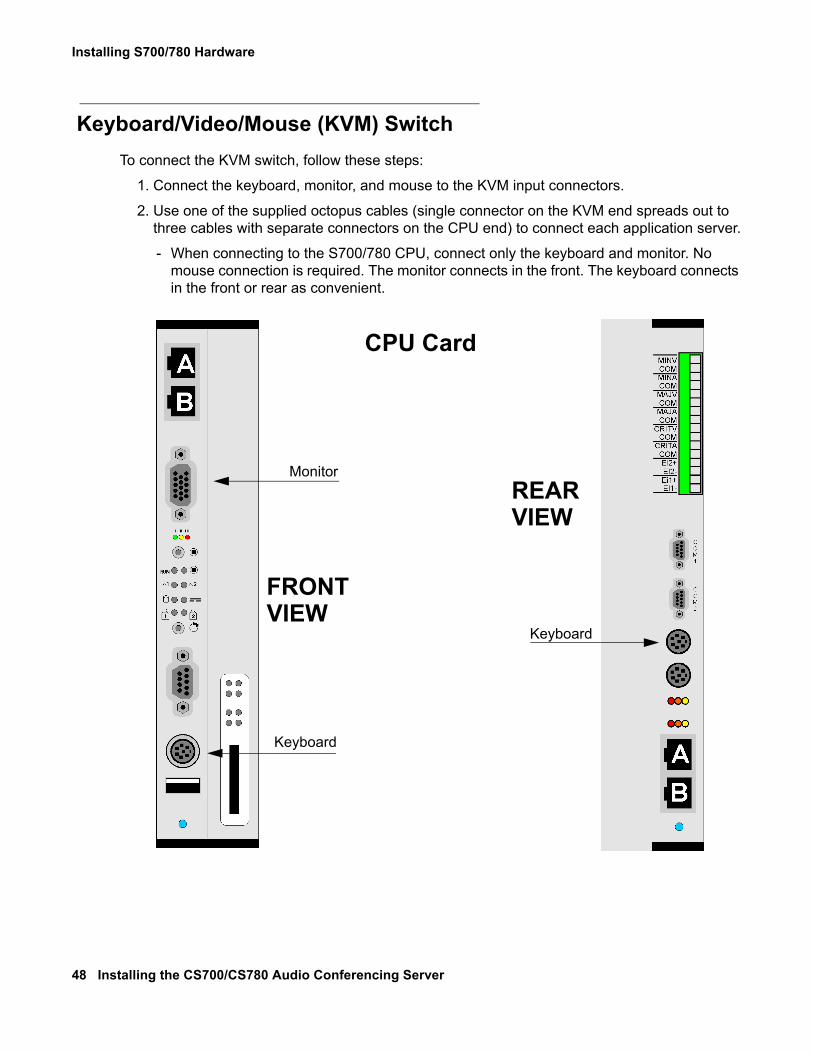
Keyboard/Video/Mouse (KVM) SwitchTo connect the KVM switch, follow these steps:
1. Connect the keyboard, monitor, and mouse to the KVM input connectors.
2. Use one of the supplied octopus cables (single connector on the KVM end spreads out to three cables with separate connectors on the CPU end) to connect each application server.
- When connecting to the S700/780 CPU, connect only the keyboard and monitor. No mouse connection is required. The monitor connects in the front. The keyboard connects in the front or rear as convenient.
Monitor
Keyboard
CPU Card
FRONT
REAR
VIEW
VIEW
Keyboard

Connecting the System
Issue 1 November 2008 49
- When connecting to an embedded CRS, use a “Y” cable to connect both the mouse and keyboard to the single dual-purpose connector on the CRS. The monitor connects in the front. The keyboard and mouse connect in the rear.
RAID Connection (Optional)The Dot Hill RAID system has two independent bus segments that can be connected to separate S700/780 conferencing servers. The RAID system will be provided in one of the following configurations:
● Single CPU setup populated with three disks and one hot spare.
● Dual CPU setup populated with three disks and one hot spare for each segment.
Monitor
Keyboard & Mouse(“Y” Cable)
eCRS Card
FRONTVIEW
REARVIEW
Installing S700/780 Hardware
50 Installing the CS700/CS780 Audio Conferencing Server
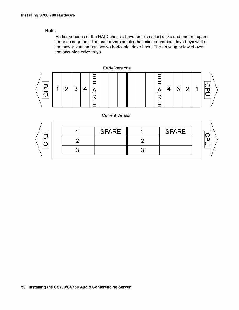
Note:Note: Earlier versions of the RAID chassis have four (smaller) disks and one hot spare
for each segment. The earlier version also has sixteen vertical drive bays while the newer version has twelve horizontal drive bays. The drawing below shows the occupied drive trays.
Early Versions
Current Version
Connecting the System
Issue 1 November 2008 51
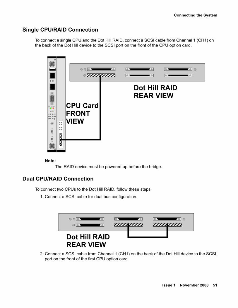
Single CPU/RAID Connection
To connect a single CPU and the Dot Hill RAID, connect a SCSI cable from Channel 1 (CH1) on the back of the Dot Hill device to the SCSI port on the front of the CPU option card.
Note:Note: The RAID device must be powered up before the bridge.
Dual CPU/RAID Connection
To connect two CPUs to the Dot Hill RAID, follow these steps:
1. Connect a SCSI cable for dual bus configuration.
2. Connect a SCSI cable from Channel 1 (CH1) on the back of the Dot Hill device to the SCSI port on the front of the first CPU option card.
CRIT MAJ MIN
ACO
ACORUN
PWRIDE
USB2
USB1
CPU CardFRONTVIEW
Dot Hill RAIDREAR VIEW
Dot Hill RAIDREAR VIEW
Installing S700/780 Hardware
52 Installing the CS700/CS780 Audio Conferencing Server
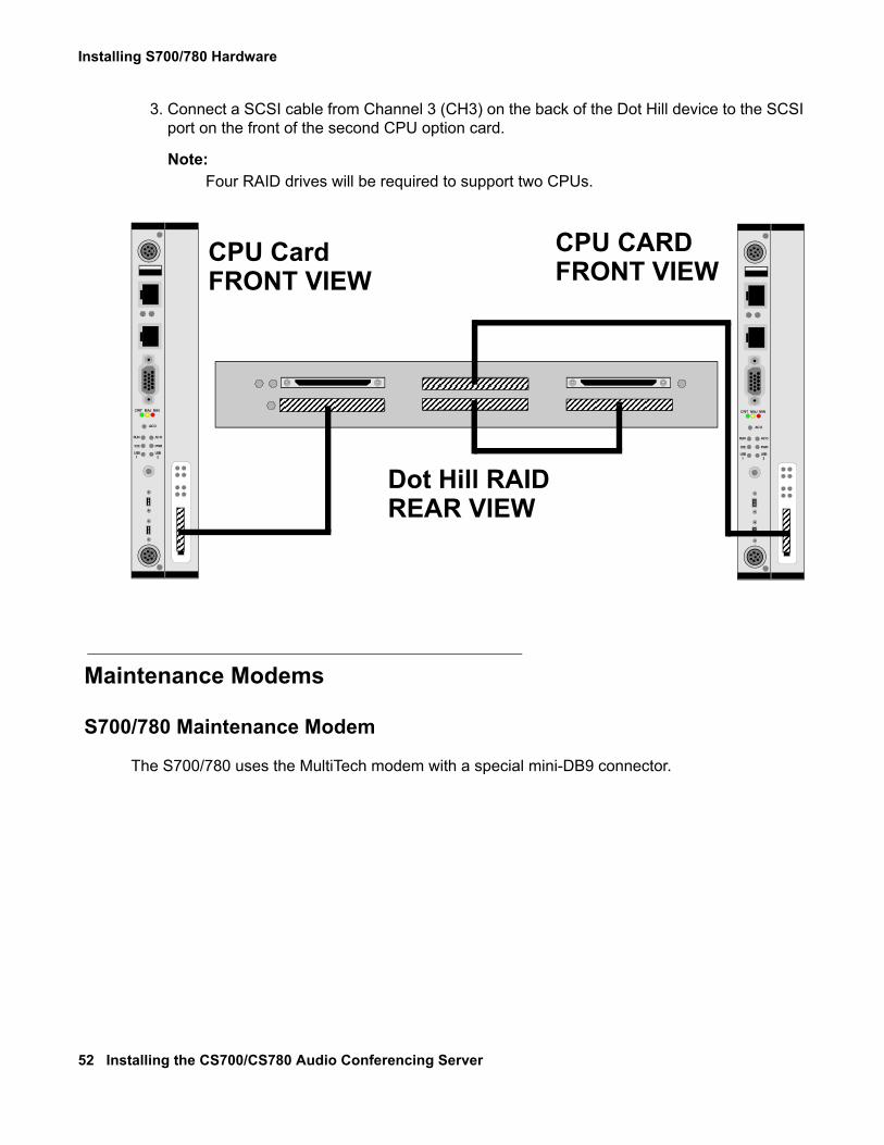
3. Connect a SCSI cable from Channel 3 (CH3) on the back of the Dot Hill device to the SCSI port on the front of the second CPU option card.
Note:Note: Four RAID drives will be required to support two CPUs.
Maintenance Modems
S700/780 Maintenance Modem
The S700/780 uses the MultiTech modem with a special mini-DB9 connector.
CRIT MAJ MIN
ACO
ACORUN
PWRIDE
USB2
USB1
CRIT MAJ MIN
ACO
ACORUN
PWRIDE
USB2
USB1
CPU CardFRONT VIEW
CPU CARDFRONT VIEW
Dot Hill RAIDREAR VIEW
Connecting the System
Issue 1 November 2008 53
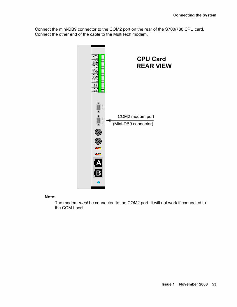
Connect the mini-DB9 connector to the COM2 port on the rear of the S700/780 CPU card. Connect the other end of the cable to the MultiTech modem.
Note:Note: The modem must be connected to the COM2 port. It will not work if connected to
the COM1 port.
COM2 modem port
(Mini-DB9 connector)
REAR VIEWCPU Card
Installing S700/780 Hardware
54 Installing the CS700/CS780 Audio Conferencing Server
Embedded CRS Modem
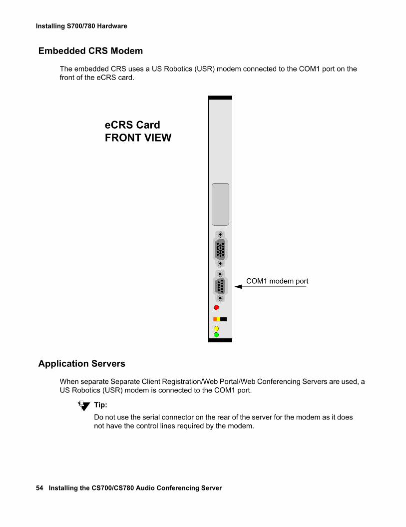
The embedded CRS uses a US Robotics (USR) modem connected to the COM1 port on the front of the eCRS card.
Application Servers
When separate Separate Client Registration/Web Portal/Web Conferencing Servers are used, a US Robotics (USR) modem is connected to the COM1 port.
Tip:Tip: Do not use the serial connector on the rear of the server for the modem as it does
not have the control lines required by the modem.
COM1 modem port
FRONT VIEWeCRS Card
Connecting the System
Issue 1 November 2008 55
LAN Connections
! Important:Important: Connect the primary LAN to Ethernet Port B with a 5550 CPU and Port A with a
5551 CPU. If there is nothing plugged into Port A with a 5551, the LAN connection will not fail over and activate on Port B. Optionally, you can plug the primary LAN to Port A for both a 5550 and a 5551 CPU and delete the Port B LAN option if no failover is being used. If a secondary LAN is later added, Port B can be added back to the configurations using SCOAdmin.
If a secondary LAN is provided, Avaya Support will configure the backup LAN on the CPU card as needed.
Installing S700/780 Hardware
56 Installing the CS700/CS780 Audio Conferencing Server
T1 Systems CPU Card (Normal)
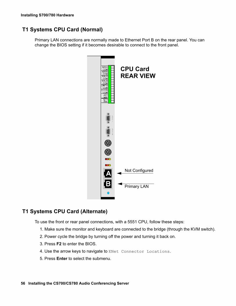
Primary LAN connections are normally made to Ethernet Port B on the rear panel. You can change the BIOS setting if it becomes desirable to connect to the front panel.
T1 Systems CPU Card (Alternate)
To use the front or rear panel connections, with a 5551 CPU, follow these steps:
1. Make sure the monitor and keyboard are connected to the bridge (through the KVM switch).
2. Power cycle the bridge by turning off the power and turning it back on.
3. Press F2 to enter the BIOS.
4. Use the arrow keys to navigate to ENet Connector Locations.
5. Press Enter to select the submenu.
Primary LAN
CPU CardREAR VIEW
Not Configured
Connecting the System
Issue 1 November 2008 57
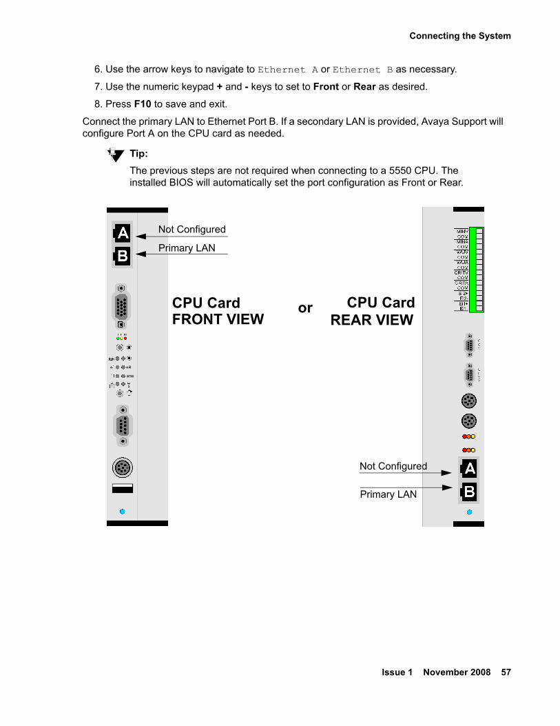
6. Use the arrow keys to navigate to Ethernet A or Ethernet B as necessary.
7. Use the numeric keypad + and - keys to set to Front or Rear as desired.
8. Press F10 to save and exit.
Connect the primary LAN to Ethernet Port B. If a secondary LAN is provided, Avaya Support will configure Port A on the CPU card as needed.
Tip:Tip: The previous steps are not required when connecting to a 5550 CPU. The
installed BIOS will automatically set the port configuration as Front or Rear.
Primary LAN
Not Configured
Primary LAN
Not Configured
CPU CardFRONT VIEW
or CPU CardREAR VIEW
Installing S700/780 Hardware
58 Installing the CS700/CS780 Audio Conferencing Server
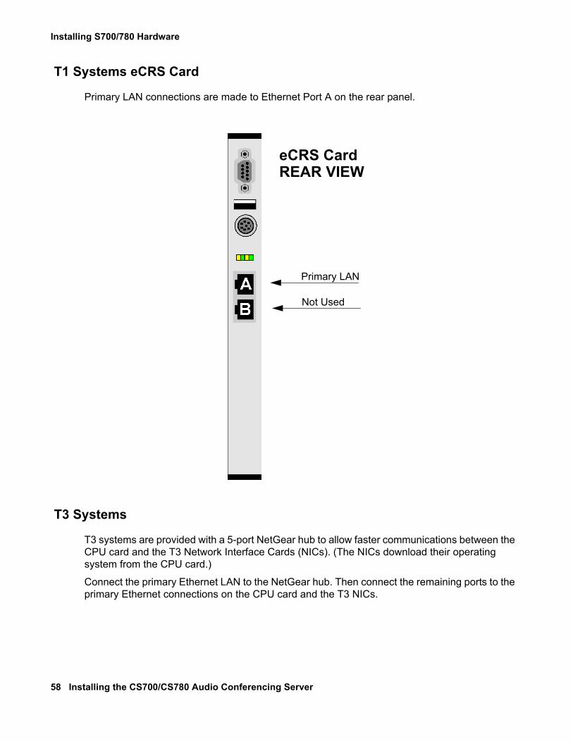
T1 Systems eCRS Card
Primary LAN connections are made to Ethernet Port A on the rear panel.
T3 Systems
T3 systems are provided with a 5-port NetGear hub to allow faster communications between the CPU card and the T3 Network Interface Cards (NICs). (The NICs download their operating system from the CPU card.)
Connect the primary Ethernet LAN to the NetGear hub. Then connect the remaining ports to the primary Ethernet connections on the CPU card and the T3 NICs.
Primary LAN
Not Used
eCRS CardREAR VIEW
Connecting the System
Issue 1 November 2008 59
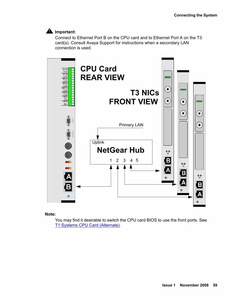
! Important:Important: Connect to Ethernet Port B on the CPU card and to Ethernet Port A on the T3
card(s). Consult Avaya Support for instructions when a secondary LAN connection is used.
Note:Note: You may find it desirable to switch the CPU card BIOS to use the front ports. See
T1 Systems CPU Card (Alternate).
CPU CardREAR VIEW
T3 NICsFRONT VIEW
NetGear Hub
Primary LAN
1 2 3 4
Uplink
5
Installing S700/780 Hardware
60 Installing the CS700/CS780 Audio Conferencing Server
Setting Up T3 Cards for LAN
The rear transition module for the T3 has a console port near the bottom of the card. Connect a serial cable, provided with the bridge, to COM1 or COM2 on your console.
Use a dumb terminal or a laptop running hyperterminal configured for 9600 baud, 1 stop, N parity, and no handshaking.
When the card is reset (power cycle), there is a 5-second countdown when autoboot is enabled. To configure the card, interrupt the countdown by hitting any key.
To set the IP address and parameters for each T3 card, follow these steps:
1. When you receive the tslinux prompt, type set.
tslinux> set
A list of parameters and values displays:
autoboot : yesbaudrate : 9600boardAddress : <ip address>cmdLine : console=ttyS0,%r ip=%b:%h:<gateway address>:255.255.255.0:<card name>:eth0 nfsroot=%h:/sberoot mem=124MgoAddress : 0x00400000hostAddress : <bridges ip address>imageName : jImage2.bin.4.0loadAddress : 0x00400000pciBoot : nouseBootp : nouseTftp : yesenetAPort : frontenetBPort : frontbootEnet : ENET-A
2. To change a value, use:
tslinux> set [option name] [value]
(for example, set boardAddress 192.168.1.123)
3. Save your changes, type store.
tslinux> store
Repeat steps 1, 2, and 3 for each T3 card.
Note:Note: Additional setup for T3 cards must be performed by Avaya Support. These steps
allow remote access to the T3 cards for configuration.
Connecting the System
Issue 1 November 2008 61
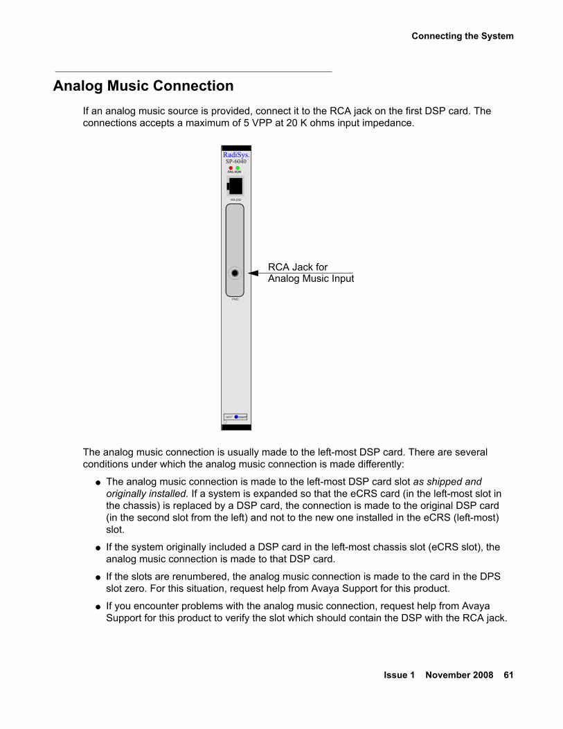
Analog Music ConnectionIf an analog music source is provided, connect it to the RCA jack on the first DSP card. The connections accepts a maximum of 5 VPP at 20 K ohms input impedance.
The analog music connection is usually made to the left-most DSP card. There are several conditions under which the analog music connection is made differently:
● The analog music connection is made to the left-most DSP card slot as shipped and originally installed. If a system is expanded so that the eCRS card (in the left-most slot in the chassis) is replaced by a DSP card, the connection is made to the original DSP card (in the second slot from the left) and not to the new one installed in the eCRS (left-most) slot.
● If the system originally included a DSP card in the left-most chassis slot (eCRS slot), the analog music connection is made to that DSP card.
● If the slots are renumbered, the analog music connection is made to the card in the DPS slot zero. For this situation, request help from Avaya Support for this product.
● If you encounter problems with the analog music connection, request help from Avaya Support for this product to verify the slot which should contain the DSP with the RCA jack.
HOT SWAP
RadiSys.SP-6040
FAIL RUN
PMC
RS-232
RCA Jack forAnalog Music Input
Installing S700/780 Hardware
62 Installing the CS700/CS780 Audio Conferencing Server
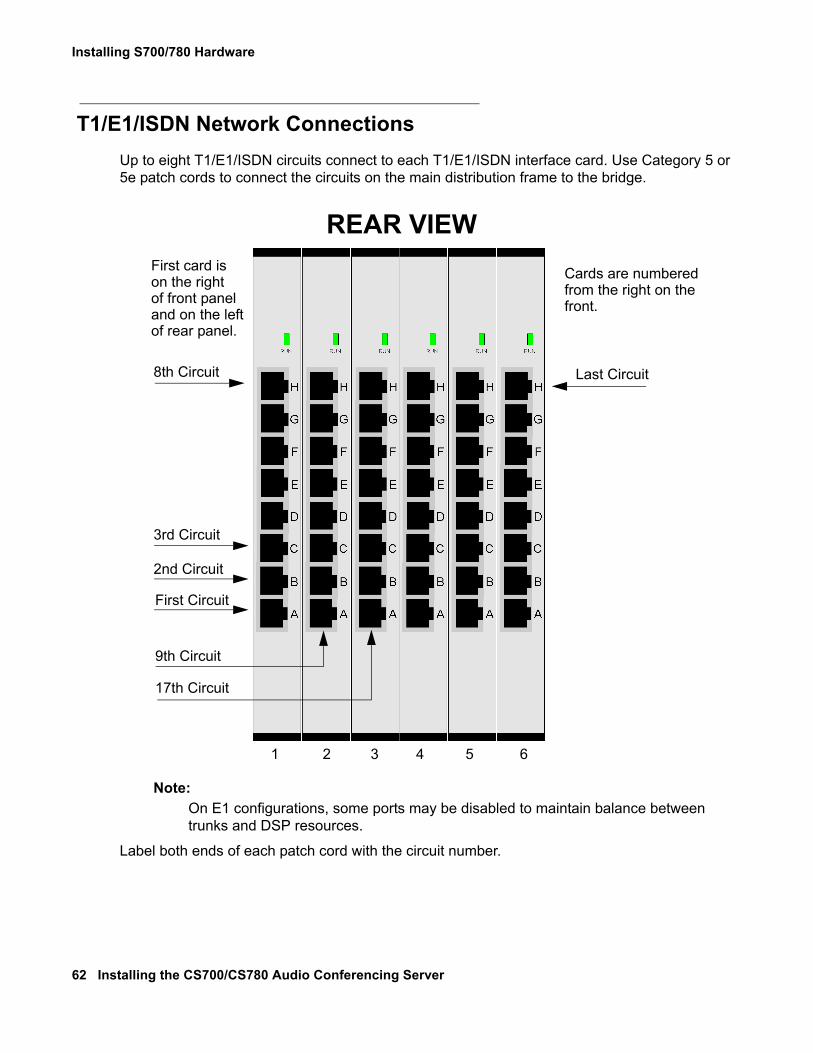
T1/E1/ISDN Network ConnectionsUp to eight T1/E1/ISDN circuits connect to each T1/E1/ISDN interface card. Use Category 5 or 5e patch cords to connect the circuits on the main distribution frame to the bridge.
Note:Note: On E1 configurations, some ports may be disabled to maintain balance between
trunks and DSP resources.
Label both ends of each patch cord with the circuit number.
1 2 3 4 5 6
First Circuit
Last Circuit
2nd Circuit
3rd Circuit
9th Circuit
17th Circuit
8th Circuit
REAR VIEWFirst card ison the rightof front paneland on the leftof rear panel.
Cards are numberedfrom the right on thefront.
Connecting the System
Issue 1 November 2008 63
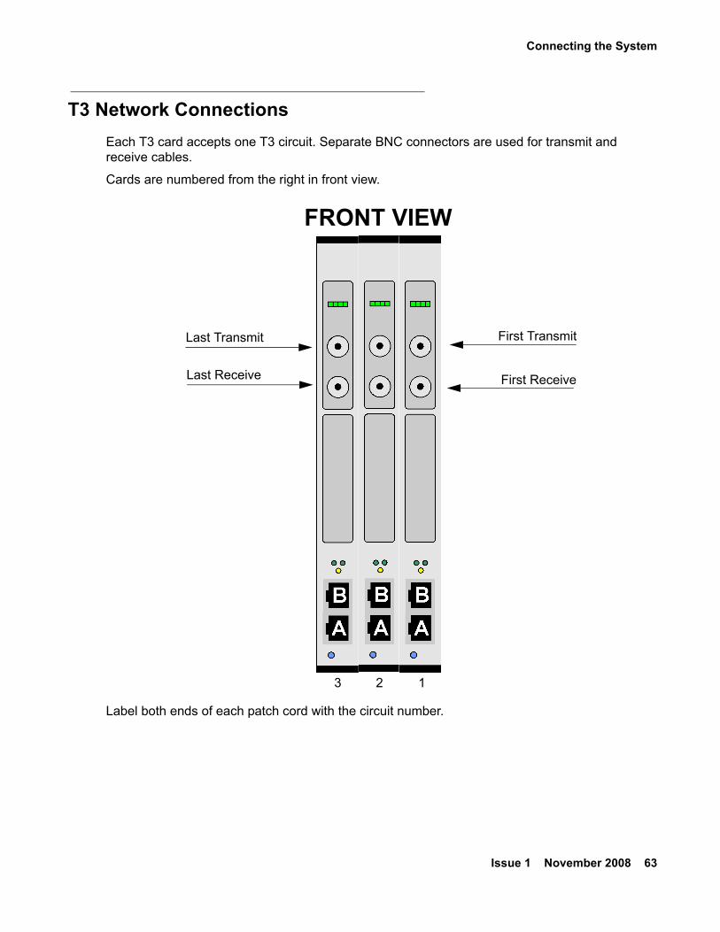
T3 Network ConnectionsEach T3 card accepts one T3 circuit. Separate BNC connectors are used for transmit and receive cables.
Cards are numbered from the right in front view.
Label both ends of each patch cord with the circuit number.
123
First Receive
First Transmit
Last Receive
Last Transmit
FRONT VIEW
Installing S700/780 Hardware
64 Installing the CS700/CS780 Audio Conferencing Server
Alarm Relay Connections (CS700 Only)Alarm relay connections for the CS700 are provided at the terminal strip on the top of the CPU rear panel transition card. The customer must provide an appropriate connector or wiring harness.
● The alarm contacts are dry relay contacts configured by default to be normally open, but can be configured to be normally closed with jumpers on the transition cards. See “Alarm Contact Configuration” below.
● There are two sets of contacts, one for visual alarms (V) and one for audible (A) alarms.
● Within “visual” and “audible,” each set has contacts for Critical, Major and Minor alarms.
● “Ei1” and “Ei2” are not used.
● Initially, when an alarm is asserted, both the audible and visual contacts for that alarm will be activated.
● If the user presses the Alarm Cut-Off button (ACO) on either the CPU front panel or the transition card panel, the audible alarm contacts will be de-activated.
● The visual alarm contact will be de-activated when the alarm condition is cleared.
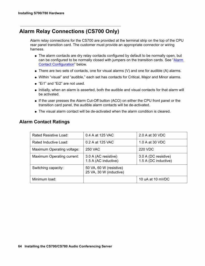
Alarm Contact Ratings
Rated Resistive Load: 0.4 A at 125 VAC 2.0 A at 30 VDC
Rated Inductive Load: 0.2 A at 125 VAC 1.0 A at 30 VDC
Maximum Operating voltage: 250 VAC 220 VDC
Maximum Operating current: 3.0 A (AC resistive)1.5 A (AC inductive)
3.0 A (DC resistive)1.5 A (DC inductive)
Switching capacity: 50 VA, 60 W (resistive)25 VA, 30 W (inductive)
Minimum load: 10 uA at 10 mVDC
Connecting the System
Issue 1 November 2008 65
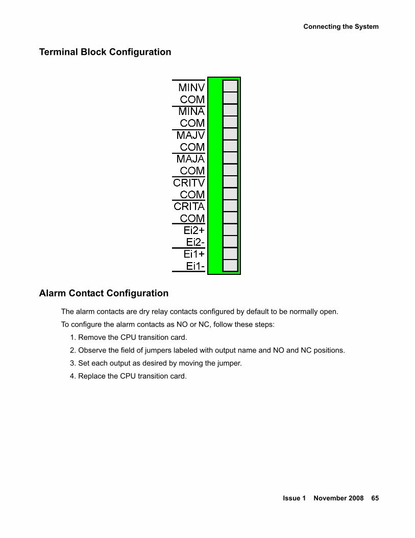
Terminal Block Configuration
Alarm Contact Configuration
The alarm contacts are dry relay contacts configured by default to be normally open.
To configure the alarm contacts as NO or NC, follow these steps:
1. Remove the CPU transition card.
2. Observe the field of jumpers labeled with output name and NO and NC positions.
3. Set each output as desired by moving the jumper.
4. Replace the CPU transition card.
Installing S700/780 Hardware
66 Installing the CS700/CS780 Audio Conferencing Server
Power Up and Initial Testing
Power Up SequenceIf RAID storage is present, it should be powered up and ready before any bridges that connect to it are powered up.
Remember to power up the KVM switch, the maintenance modems, and any application servers before powering up the bridge.
Setting IP Addresses
Set IP Address for S700/780 CPU
Note:Note: To login as root, you must request the assistance of Avaya Support for this
product.
To set the IP address for the S700/780 CPU, follow these steps:
1. Switch the KVM switch to the S700/780 CPU.
2. Log in as root.
3. Open scoadmin.
scoadmin
4. Select Networking | Network Configuration Manager.5. Select TCP/IP.
6. Select View Protocol.7. Check current settings for customer IP information. Make sure the settings specify the
correct values.
Set IP Address for Application Servers
All application servers (separate or embedded CRS, Web Portal, Web Conferencing) run Windows 2003 Server.
Note:Note: To log in as an administrator, you must request the assistance of Avaya Support
for this product.
Power Up and Initial Testing
Issue 1 November 2008 67
For each application server, follow these steps:
1. Set the KVM switch to connect the keyboard, monitor, and mouse to the application server.
2. Click Start.3. Select Settings |Control Panel.4. Double-click Network Connections.
5. Select the network interface card.
6. Select File | Properties (or right-click and select Properties).
7. Select Internet Protocol (TCP/IP).8. Click Properties.
9. Enter the IP Address, Subnet Mask, and Default Gateway address from the Site Survey.
10. Enter the Preferred DNS Server and Alternate DNS Server addresses from the Site Survey.
11. Click OK.
12. Click OK.
Board Swapping● DSP cards may be hot-swapped in any system that has more than one DSP card. See
Board Swapping (Hot Swap DSP) on page 69.
● T1/E1/PRI cards may be hot-swapped when the feature has been installed, when all installed cards are NS301, and when all replacement cards are NS301 revision AC or later. See Board Swapping (Hot Swap T1/E1/PRI NIC) on page 70.
! Important:Important: For all other board swaps, you MUST shut down the system.
Swapping Cards (Normal Shut down)Unless the system has failed, follow these steps to shut down the system to replace cards:
1. Shut down any embedded CRS first.
a. Switch to the embedded CRS on the KVM switch.
b. Double-click the “Do Stop” Icon on the screen. This will shut down the Billing/Scheduling Monitor (BS) and allow you to shut down all applications.
c. Close all applications. (The applications will be minimized at the bottom of the screen.)
d. Click “start.”
e. Click “shutdown.”
Installing S700/780 Hardware
68 Installing the CS700/CS780 Audio Conferencing Server
2. After the CRS is shut down, shut down the bridge. Switch back over to the bridge on the KVM switch.
3. Press the Enter key on the keyboard. The Log In prompt will appear.
4. For the Login name, enter dcbmaint and press Enter.
5. For the password, enter mlink700 and press Enter.
You will now be logged into the Main Maintenance Menu.
6. Using the arrow keys, arrow down to the menu entry for System Shut Down.
7. Press the Enter key.
8. Enter the word yes.
The bridge will begin to shut down.
9. When you see the message that it is safe to power the system off, shut off the power switch/es on the back of the bridge.
10. Be sure you are wearing an ESD strap that is connected to a proper ground.
11. Locate the card to be replaced.
12. Loosen the captive screws on the front top and bottom of the card.
13. Grasping the black tabs (top and bottom) of the card, push them away from each other. This will extract the card from the backplane.
14. Slide the card completely out of the chassis.
15. Place the new card in the correct slot and slide it in until it is firmly seated in the backplane.
! CAUTION:CAUTION: Pins on the backplane are delicate and bend easily. Do not touch the card,
components, or connectors. Handle only by the edges.
16. Lock the black tabs to fully engage the card.
17. Tighten the captive screws.
18. Power up the bridge. Turn up the power to the modem(s), monitor, KVM switch, and bridge. If RAID equipped, turn up power to the RAID array first. Verify that the bridge powers up correctly. Watch the monitor and verify there are no errors.
If equipped with an embedded CRS blade, the CRS will power up when you power up the bridge.
Swapping Cards (System Failure)
If the system has failed so that a shutdown is not possible, follow these steps:
1. Shut off the power switch/es onthe back of the bridge.
2. Be sure you are wearing an ESD strap that is connected to a proper ground.
Power Up and Initial Testing
Issue 1 November 2008 69
3. Locate the card to be replaced.
4. Loosen the captive screws on the front top and bottom of the card.
5. Grasping the black tabs (top and bottom) of the card, push them away from each other. This will extract the card from the backplane.
6. Slide the card completely out of the chassis.
7. Place the new card in the correct slot and slide it in until it is firmly seated in the backplane.
! CAUTION:CAUTION: Pins on the backplane are delicate and bend easily. Do not touch the card,
components, or connectors. Handle only by the edges.
8. Lock the black tabs to fully engage the card.
9. Tighten the captive screws.
10. Power up the bridge. Turn up the power to the modem(s), monitor, KVM switch, and bridge. If RAID equipped, turn up power to the RAID array first. Verify that the bridge powers up correctly. Watch the monitor and verify there are no errors.
If equipped with an embedded CRS blade, the CRS will power up when you power up the bridge.
Board Swapping (Hot Swap DSP)
Note:Note: If there is only one DSP, it cannot be hot-swapped. Use the procedure in
“Swapping Cards (Normal Shut down) on page 67” to shut the system down and swap the card.
To hot swap a DSP, follow these steps:
1. Be sure you are wearing an ESD strap that is connected to a proper ground.
2. Loosen the captive screws.
3. Flip the card’s top latch half-way up and bottom latch half-way down.
The blue hot swap LED will light.
! CAUTION:CAUTION: Wait for the blue hot swap LED to light before disengaging card.
4. Flip the top and bottom latches all the way to disengage the card, and slide the card out of the chassis.
5. Place the new card in the slot, and slide it in until it is firmly seated in the backplane.
! CAUTION:CAUTION: Pins on the backplane are delicate and bend easily. Do not touch the card,
components, or connectors. Handle only by the edges.
Installing S700/780 Hardware
70 Installing the CS700/CS780 Audio Conferencing Server
6. Lock the black tabs to fully engage the card.
7. Tighten the captive screws.
Board Swapping (Hot Swap T1/E1/PRI NIC)
Note:Note: If there is only one NIC, it cannot be hot-swapped. Use the procedure in
“Swapping Cards (Normal Shut down) on page 67“ to shut the system down and swap the card.
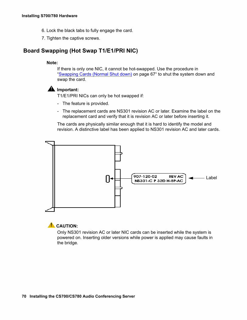
! Important:Important: T1/E1/PRI NICs can only be hot swapped if:
- The feature is provided.
- The replacement cards are NS301 revision AC or later. Examine the label on the replacement card and verify that it is revision AC or later before inserting it.
The cards are physically similar enough that it is hard to identify the model and revision. A distinctive label has been applied to NS301 revision AC and later cards.
! CAUTION:CAUTION: Only NS301 revision AC or later NIC cards can be inserted while the system is
powered on. Inserting older versions while power is applied may cause faults in the bridge.
Label
Power Up and Initial Testing
Issue 1 November 2008 71
To hot swap a NIC, follow these steps:
1. Switch to the bridge on the KVM switch.
2. At the prompt, type:
isdnmgr -stop <boardNumber>
where the boards are numbered from 1 starting on the right of the front panel.
3. Be sure you are wearing an ESD strap that is connected to a proper ground.
4. Loosen the captive screws.
5. Wait approximately 30 seconds for the blue hot swap LED to light.
6. Flip the top and bottom latches all the way to disengage the card, and slide the card out of the chassis.
7. Place the new card in the slot, and slide it in until it is firmly seated in the backplane. Use caution as the pins on the backplane are delicate and bend easily. Take care to not touch the card, components or connectors. Handle only by the edges.
8. Lock the black tabs to fully engage the card.
9. Tighten the captive screws.
10. At the prompt type:
isdnmgr -start <boardNumber>
Installing S700/780 Hardware
72 Installing the CS700/CS780 Audio Conferencing Server
Cleaning Up and Labeling the SystemTo clean up and label the system, follow these steps:
1. Label all hardware with name and IP address.
2. Label each end of each cable, except network cabling, with where it comes from and where it connects to.
3. Label each end of each network cable with the circuit identification. (Adding cards when expanding a system may involve moving cables.)
4. Make sure there are no loose cables or wires hanging from the system. This could cause injury to personnel or the system if a cable is accidentally pulled. All cables should be tie wrapped neatly.
5. Physically inspect the system and general area to ensure no parts, shipping material, cables, or debris are left behind.
Notifying the Help Desk as Ready for ConfigurationWhen all of the installation tasks have been completed, notify the Help Desk that the system is ready for remote configuration.
! Important:Important: Notify the Help Desk of any changes or inconsistencies you have found in IP
addresses, telephone numbers, and other items specified on the Site Survey.
Issue 1 November 2008 73
Chapter 3: Updating Hardware
Hardware update may be required for one of the following reasons:
● Activating additional user ports (adding network connections).
● Software version upgrade requires more processing power.
This chapter describes how to identify existing hardware and how to replace or add components.
Replacing and Installing Cards
Shutting Down the SystemIt is necessary to shut down the system for most hardware upgrades.
Follow these steps to shut down the system:
1. Shut down any embedded CRS.
2. Switch to the embedded CRS on the KVM switch.
a. Double-click the “Do Stop” Icon on the screen. This will shut down the Billing/Scheduling Monitor (BS) and allow you to shut down all applications.
b. Close all applications. (The applications will be minimized at the bottom of the screen.)
c. Click “start.”
d. Click “shutdown.”
3. After the CRS is shutdown, shut down the bridge.
a. Switch back over to the bridge on the KVM switch.
b. Press the Enter key on the keyboard. The Log In prompt will appear.
c. For the login, enter dcbmaint and press Enter.
d. For the password, enter dcbmaint and press Enter.
You will now be logged into the System Maintenance Main Menu.
e. Using the arrow keys, arrow down to the menu entry for System Shutdown.
f. Press the Enter key.
Updating Hardware
74 Installing the CS700/CS780 Audio Conferencing Server
g. Enter the word yes.
The bridge will begin to shut down.
h. When you see the message that it is safe to power the system off, move to the back of the bridge and shut off the power switch/es.
Replacing CardsTo replace cards, follow these steps:
1. Shut down the system.
2. Be sure you are wearing an ESD strap connected to a proper ground.
3. Locate the card to be replaced.
4. Disconnect any cables from both the front and the back of the card.
5. Loosen the captive screws on the front top and bottom of the card.
6. Grasping the black tabs (top and bottom) of the card, push them away from each other. This will extract the card from the backplane.
7. Slide the card completely out of the chassis.
8. Place the new card in the correct slot and slide it in until it is firmly seated in the backplane.
! CAUTION:CAUTION: Pins on the backplane are delicate and bend easily. Do not touch the card,
components, or connectors. Handle only by the edges.
9. Lock the black tabs to fully engage the card.
10. Tighten the captive screws.
11. Connect any necessary cables.
12. Power up the bridge. Turn on the power to the modem(s), monitor, KVM switch, and bridge. If RAID equipped, turn up power to the RAID array first. Verify that the bridge powers up correctly. Watch the monitor and verify there are no errors.
If equipped with an embedded CRS blade, the CRS will power up when you power up the bridge.
Identifying Outdated Equipment
Issue 1 November 2008 75
Adding CardsSee the description of individual cards to determine whether transition cards (rear) are also required.
To add cards, follow these steps:
1. Shut down the system.
2. Be sure you are wearing an ESD strap connected to a proper ground.
3. Locate the filler panel that covers the slot.
4. Loosen the screws on the top and bottom of the filler panel.
5. Remove the filler panel from the chassis.
6. If a transition card (rear) is also to be added, remove the filler panel from the rear of the same slot.
7. Place the new card in the correct slot, and slide it in until it is firmly seated in the backplane.
! CAUTION:CAUTION: Pins on the backplane are delicate and bend easily. Do not touch the card,
components, or connectors. Handle only by the edges.
8. Lock the black tabs to fully engage the card.
9. Tighten the captive screws.
10. If a transition card (rear) is also to be added, install the transition card in the rear of the same slot.
11. Connect any necessary cables.
12. Power up the bridge. Turn up the power to the modem(s), monitor, KVM switch and bridge. If RAID equipped, turn up power to the RAID array first. Verify that the bridge powers up correctly. Watch the monitor and verify there are no errors.
If equipped with an embedded CRS blade, the CRS will power up when you power up the bridge.
Identifying Outdated EquipmentOnly the CPU card and the T1/E1/PRI NIC card have multiple versions. Any update will use the latest available version. It may also be necessary to update to a combination CD/Floppy drive when updating the CPU card.
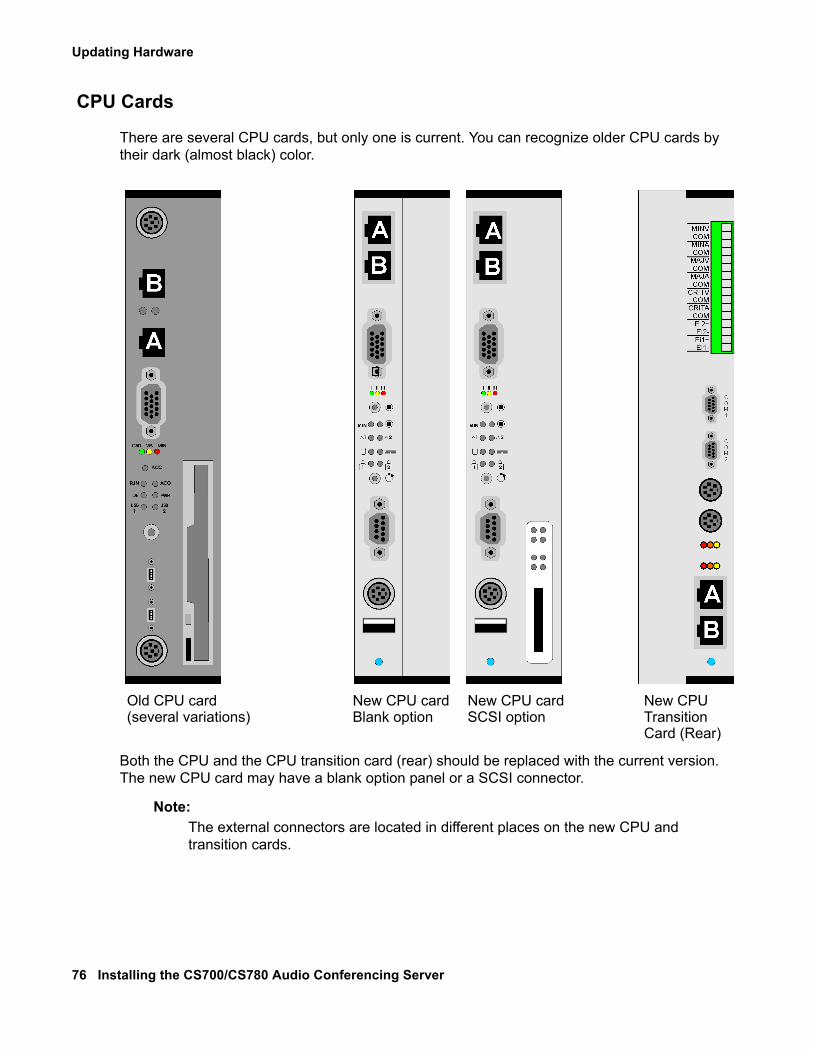
Updating Hardware
76 Installing the CS700/CS780 Audio Conferencing Server
CPU Cards
There are several CPU cards, but only one is current. You can recognize older CPU cards by their dark (almost black) color.
Both the CPU and the CPU transition card (rear) should be replaced with the current version. The new CPU card may have a blank option panel or a SCSI connector.
Note:Note: The external connectors are located in different places on the new CPU and
transition cards.
Old CPU card(several variations)
New CPU cardBlank option
New CPU cardSCSI option
New CPUTransitionCard (Rear)
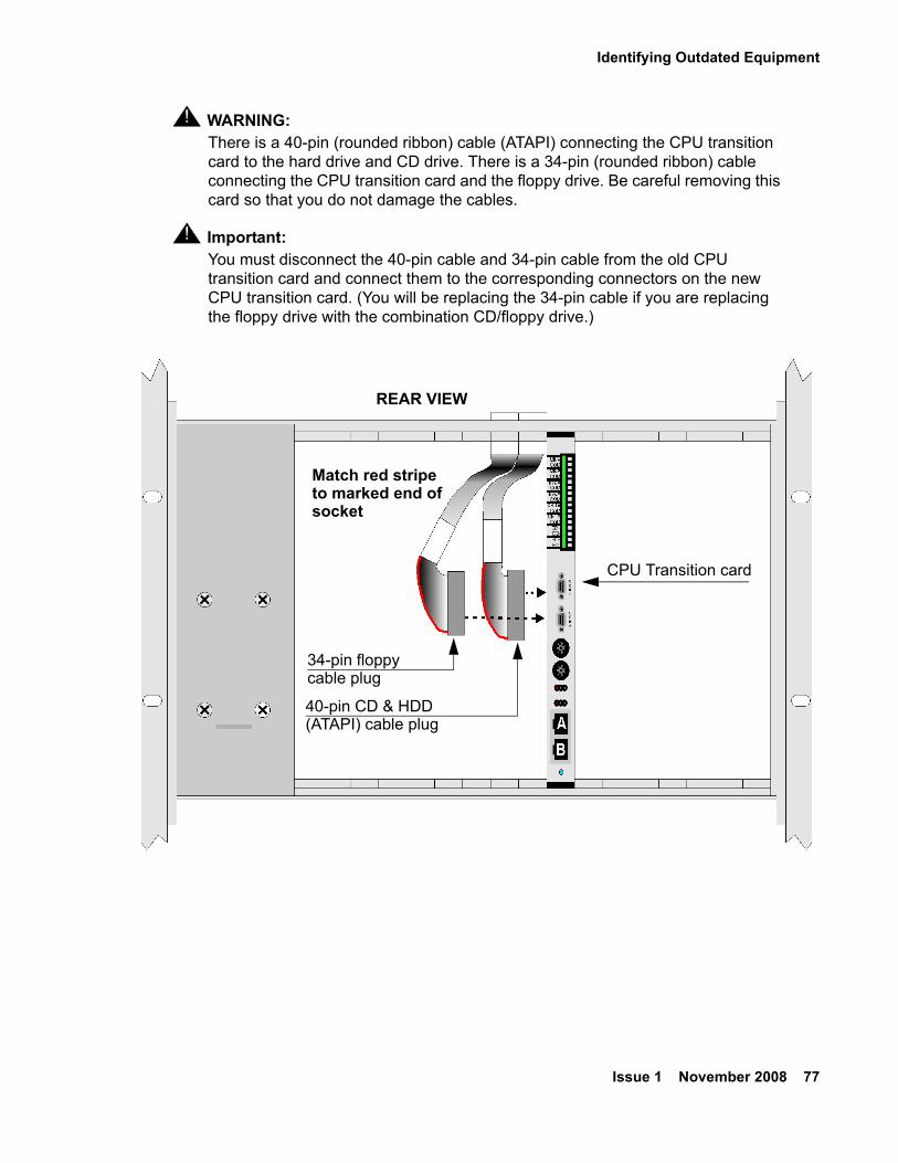
Identifying Outdated Equipment
Issue 1 November 2008 77
! WARNING:WARNING: There is a 40-pin (rounded ribbon) cable (ATAPI) connecting the CPU transition
card to the hard drive and CD drive. There is a 34-pin (rounded ribbon) cable connecting the CPU transition card and the floppy drive. Be careful removing this card so that you do not damage the cables.
! Important:Important: You must disconnect the 40-pin cable and 34-pin cable from the old CPU
transition card and connect them to the corresponding connectors on the new CPU transition card. (You will be replacing the 34-pin cable if you are replacing the floppy drive with the combination CD/floppy drive.)
34-pin floppy
40-pin CD & HDD
CPU Transition card
(ATAPI) cable plug
REAR VIEW
Match red stripeto marked end ofsocket
cable plug
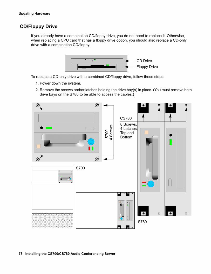
Updating Hardware
78 Installing the CS700/CS780 Audio Conferencing Server
CD/Floppy Drive
If you already have a combination CD/floppy drive, you do not need to replace it. Otherwise, when replacing a CPU card that has a floppy drive option, you should also replace a CD-only drive with a combination CD/floppy.
To replace a CD-only drive with a combined CD/floppy drive, follow these steps:
1. Power down the system.
2. Remove the screws and/or latches holding the drive bay(s) in place. (You must remove both drive bays on the S780 to be able to access the cables.)
CD DriveFloppy Drive
S700
S780
4 S
crew
s 8 Screws,4 Latches,Top andBottom
CS780
S70
0
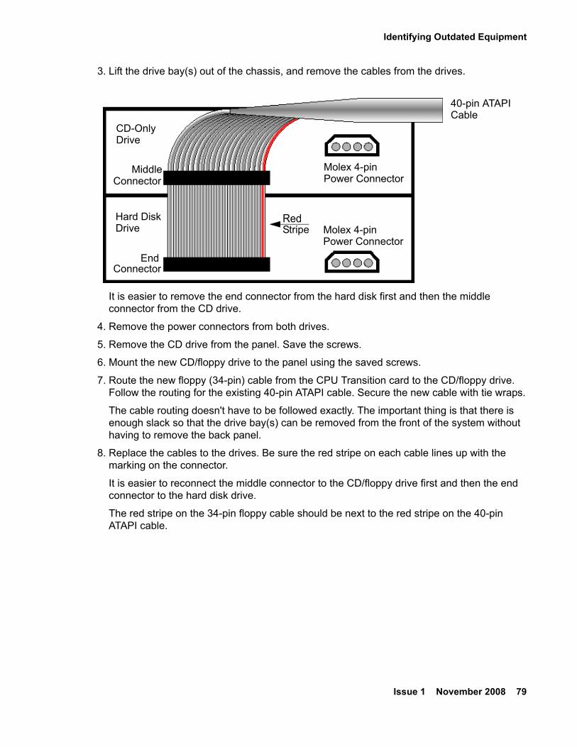
Identifying Outdated Equipment
Issue 1 November 2008 79
3. Lift the drive bay(s) out of the chassis, and remove the cables from the drives.
It is easier to remove the end connector from the hard disk first and then the middle connector from the CD drive.
4. Remove the power connectors from both drives.
5. Remove the CD drive from the panel. Save the screws.
6. Mount the new CD/floppy drive to the panel using the saved screws.
7. Route the new floppy (34-pin) cable from the CPU Transition card to the CD/floppy drive. Follow the routing for the existing 40-pin ATAPI cable. Secure the new cable with tie wraps.
The cable routing doesn't have to be followed exactly. The important thing is that there is enough slack so that the drive bay(s) can be removed from the front of the system without having to remove the back panel.
8. Replace the cables to the drives. Be sure the red stripe on each cable lines up with the marking on the connector.
It is easier to reconnect the middle connector to the CD/floppy drive first and then the end connector to the hard disk drive.
The red stripe on the 34-pin floppy cable should be next to the red stripe on the 40-pin ATAPI cable.
CD-OnlyDrive
Hard DiskDrive
40-pin ATAPICable
Molex 4-pinPower Connector
Molex 4-pinPower Connector
MiddleConnector
EndConnector
RedStripe
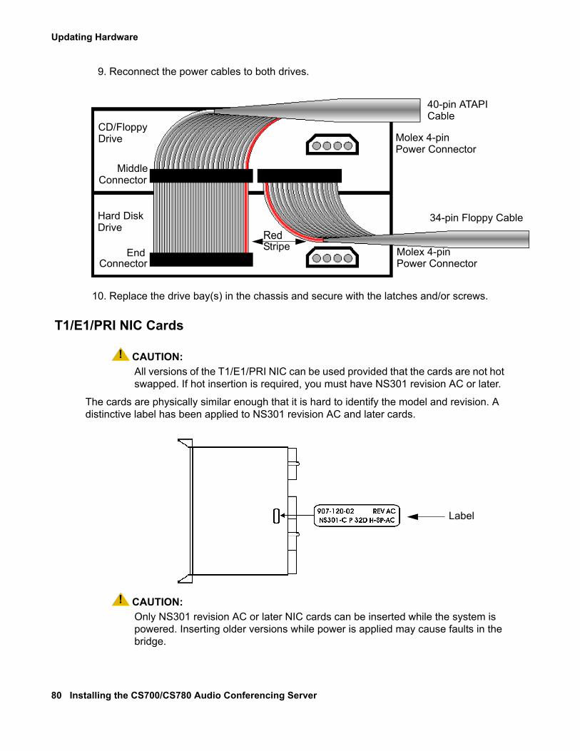
Updating Hardware
80 Installing the CS700/CS780 Audio Conferencing Server
9. Reconnect the power cables to both drives.
10. Replace the drive bay(s) in the chassis and secure with the latches and/or screws.
T1/E1/PRI NIC Cards
! CAUTION:CAUTION: All versions of the T1/E1/PRI NIC can be used provided that the cards are not hot
swapped. If hot insertion is required, you must have NS301 revision AC or later.
The cards are physically similar enough that it is hard to identify the model and revision. A distinctive label has been applied to NS301 revision AC and later cards.
! CAUTION:CAUTION: Only NS301 revision AC or later NIC cards can be inserted while the system is
powered. Inserting older versions while power is applied may cause faults in the bridge.
CD/FloppyDrive
Hard DiskDrive
40-pin ATAPICable
Molex 4-pinPower Connector
Molex 4-pinPower Connector
MiddleConnector
EndConnector
34-pin Floppy Cable
RedStripe
Label
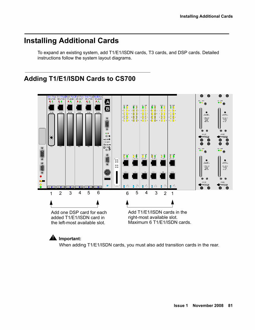
Installing Additional Cards
Issue 1 November 2008 81
Installing Additional CardsTo expand an existing system, add T1/E1/ISDN cards, T3 cards, and DSP cards. Detailed instructions follow the system layout diagrams.
Adding T1/E1/ISDN Cards to CS700
! Important:Important: When adding T1/E1/ISDN cards, you must also add transition cards in the rear.
Add one DSP card for each Add T1/E1/ISDN cards in the
Maximum 6 T1/E1/ISDN cards.added T1/E1/ISDN card in the left-most available slot.
right-most available slot.
1234561 2 3 4 5 6
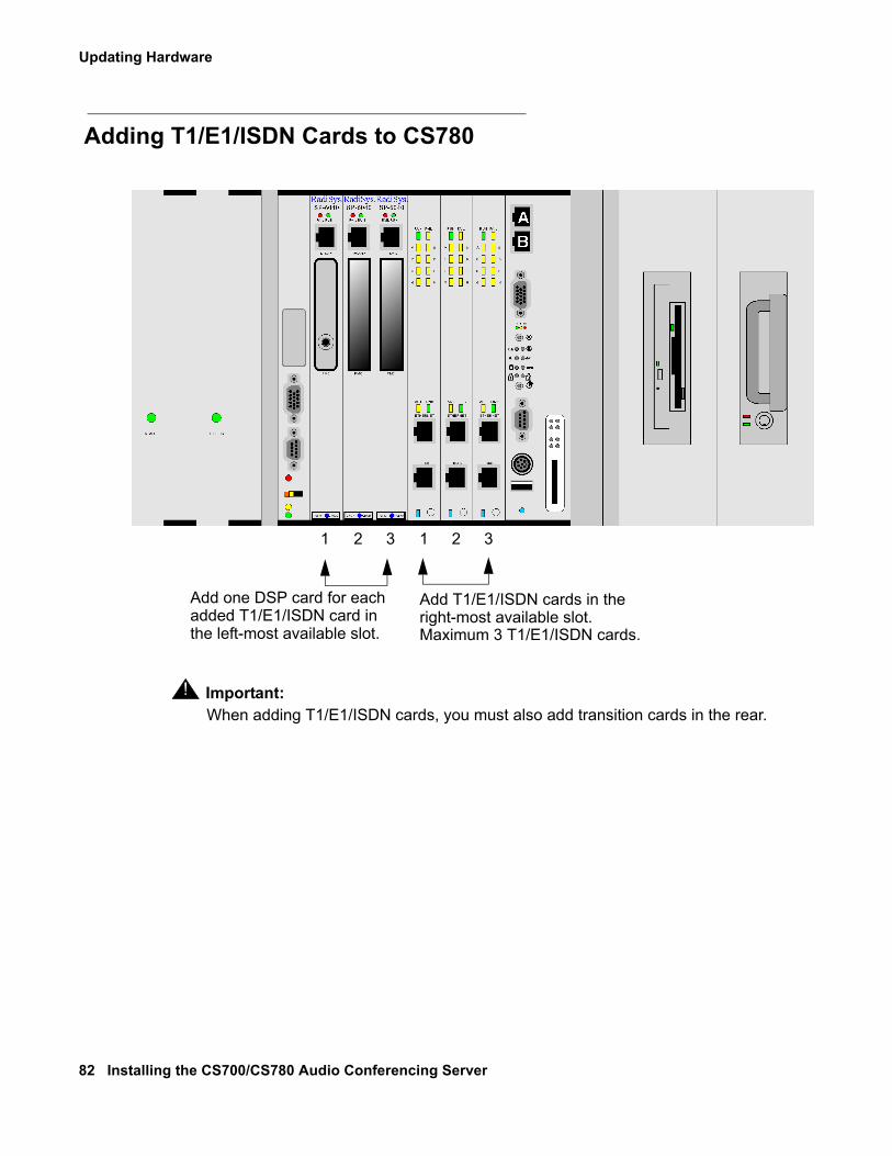
Updating Hardware
82 Installing the CS700/CS780 Audio Conferencing Server
Adding T1/E1/ISDN Cards to CS780
! Important:Important: When adding T1/E1/ISDN cards, you must also add transition cards in the rear.
Add one DSP card for each added T1/E1/ISDN card in the left-most available slot.
Add T1/E1/ISDN cards in the
Maximum 3 T1/E1/ISDN cards.right-most available slot.
1 2 3 321
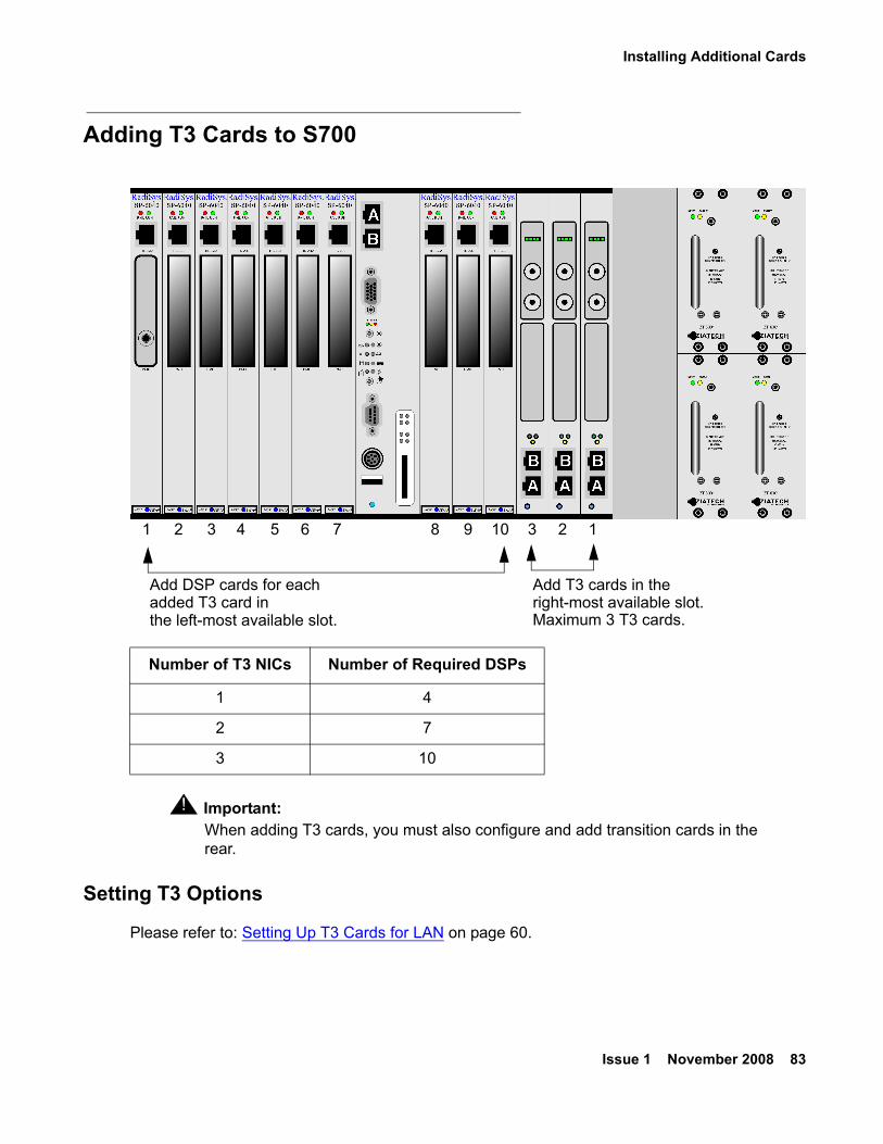
Installing Additional Cards
Issue 1 November 2008 83
Adding T3 Cards to S700
! Important:Important: When adding T3 cards, you must also configure and add transition cards in the
rear.
Setting T3 Options
Please refer to: Setting Up T3 Cards for LAN on page 60.
Number of T3 NICs Number of Required DSPs
1 4
2 7
3 10
Add DSP cards for each added T3 card in the left-most available slot.
Add T3 cards in the
Maximum 3 T3 cards.right-most available slot.
1 2 3 4 5 6 7 8 9 10 3 12
Updating Hardware
84 Installing the CS700/CS780 Audio Conferencing Server
Installing NICs/DSPsIt may be necessary to install an additional NIC when activating additional user ports to a system. For every NIC you install, you must also install at least one DSP card. There are a maximum of 10 slots available for DSPs on the CS700 and a maximum of 3 slots available for DSPs on the CS780.
● Each T1/E1/PRI NIC requires one DSP.
● The first T3 NIC requires four DSPs.
● The second and third T3 NICs require 3 DSPs each.
To install NICs/DSPs, follow these steps:
1. Shut down and power off the system.
2. Remove the filler panel covers for the NICs/DSPs and the corresponding transition cards.
3. Install and secure the cards in the appropriate slots.
● DSPs install in the left-most available slot. On the CS700, up to 7 DSPs can be installed to the left of the CPU, and up to 3 more can be installed to the right of the CPU. On the CS780, up to 3 DSPs can be installed to the far left of the CPU.
● NICs install in the right-most available slot. On the CS700, up to 6 NICs can be installed to the right of the CPU. On the CS780, up to 3 NICs can be installed to the immediate left of the CPU.
! WARNING:WARNING: NS300 and NS301 NIC cards have slide-in guides that will come in contact with
the backplane. Some older systems may have grounding pins in a location that can come in contact with the slide-in guides on the NIC cards causing them to bend or break upon installation. Therefore, before inserting any NS300 or NS301 NIC card, verify that there are no grounding pins on the backplane.
4. Turn on the system.
Note:Note: You must specify the number of cards installed in the bridge after you install
additional cards. See the management interface’s System Maintenance Main Menu > Network Configuration > Trunk Configuration > Set Board Count option as described in the Administration and Maintenance Guide for the S700/780 Conferencing Servers.
Installing Additional Cards
Issue 1 November 2008 85
Special Considerations for Analog Music ConnectionsThe analog music connection is usually made to the left-most DSP card. There are several conditions under which the analog music connection is made differently:
● The analog music connection is made to the left-most DSP card slot as shipped and originally installed. If a system is expanded so that the eCRS card (in the left-most slot in the chassis) is replaced by a DSP card, the connection is made to the original DSP card (in the second slot from the left) and not to the new one installed in the eCRS (left-most) slot.
● If the system originally included a DSP card in the left-most chassis slot (eCRS slot), the analog music connection is made to that DSP card.
● If the slots are renumbered, the analog music connection is made to the card in the DPS slot zero. For this situation, request help from Avaya Support for this product.
● If you encounter problems with the analog music connection, request help from Avaya Support for this product to verify the slot that should contain the DSP with the RCA jack.

Updating Hardware
86 Installing the CS700/CS780 Audio Conferencing Server
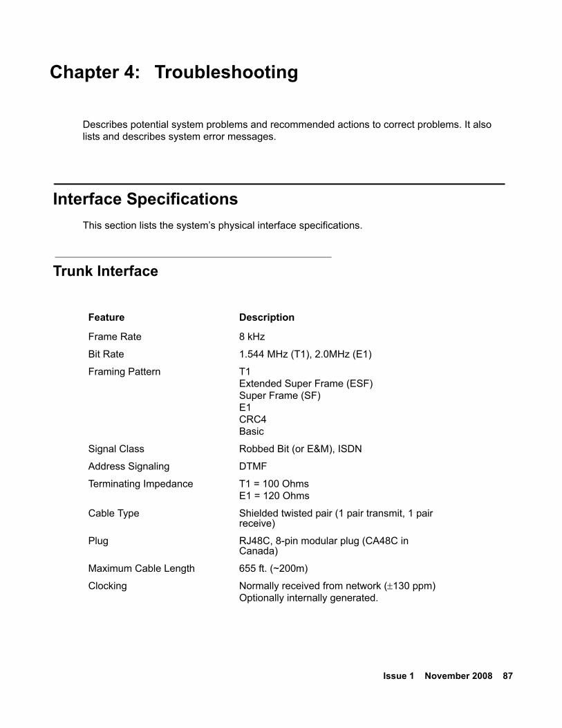
Issue 1 November 2008 87
Chapter 4: Troubleshooting
Describes potential system problems and recommended actions to correct problems. It also lists and describes system error messages.
Interface SpecificationsThis section lists the system’s physical interface specifications.
Trunk Interface
Feature Description
Frame Rate 8 kHz
Bit Rate 1.544 MHz (T1), 2.0MHz (E1)
Framing Pattern T1Extended Super Frame (ESF)Super Frame (SF)E1CRC4Basic
Signal Class Robbed Bit (or E&M), ISDN
Address Signaling DTMF
Terminating Impedance T1 = 100 OhmsE1 = 120 Ohms
Cable Type Shielded twisted pair (1 pair transmit, 1 pair receive)
Plug RJ48C, 8-pin modular plug (CA48C in Canada)
Maximum Cable Length 655 ft. (~200m)
Clocking Normally received from network (±130 ppm)Optionally internally generated.
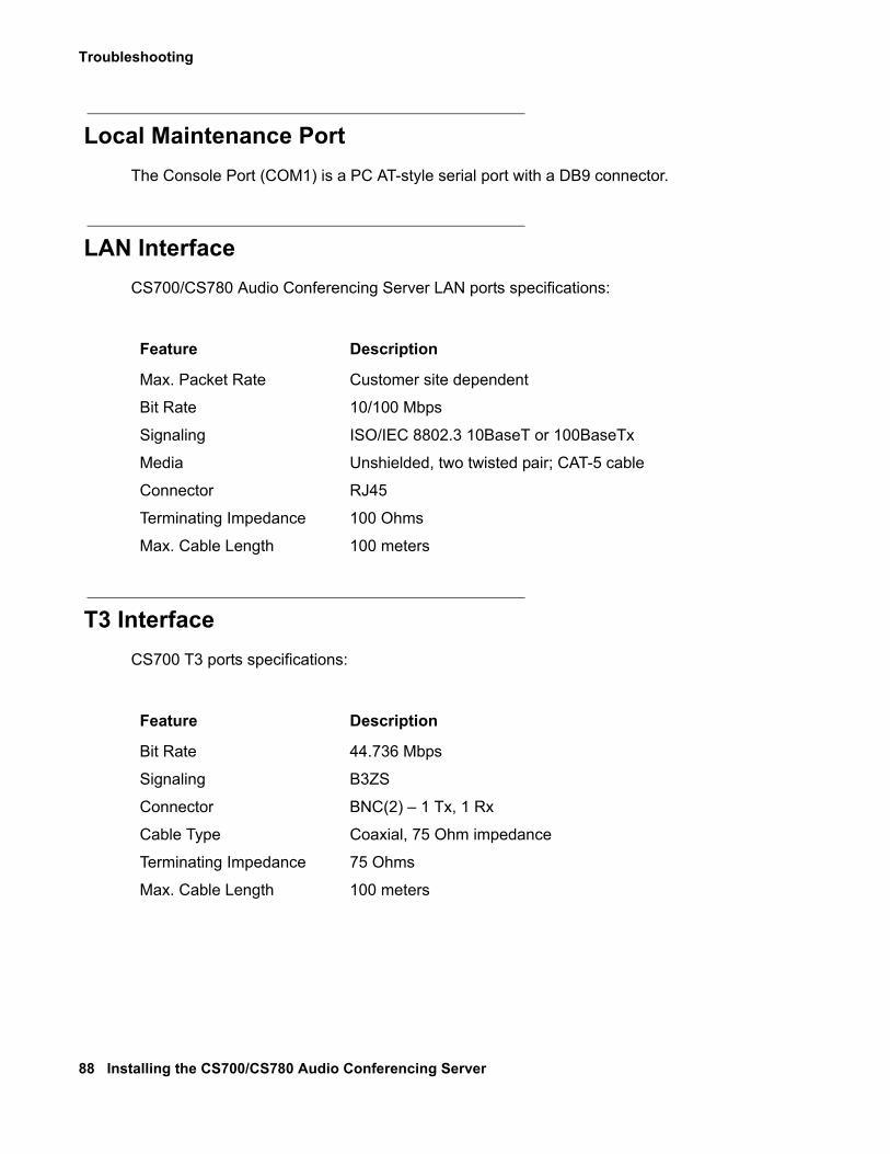
Troubleshooting
88 Installing the CS700/CS780 Audio Conferencing Server
Local Maintenance PortThe Console Port (COM1) is a PC AT-style serial port with a DB9 connector.
LAN Interface CS700/CS780 Audio Conferencing Server LAN ports specifications:
T3 InterfaceCS700 T3 ports specifications:
Feature Description
Max. Packet Rate Customer site dependent
Bit Rate 10/100 Mbps
Signaling ISO/IEC 8802.3 10BaseT or 100BaseTx
Media Unshielded, two twisted pair; CAT-5 cable
Connector RJ45
Terminating Impedance 100 Ohms
Max. Cable Length 100 meters
Feature Description
Bit Rate 44.736 Mbps
Signaling B3ZS
Connector BNC(2) – 1 Tx, 1 Rx
Cable Type Coaxial, 75 Ohm impedance
Terminating Impedance 75 Ohms
Max. Cable Length 100 meters
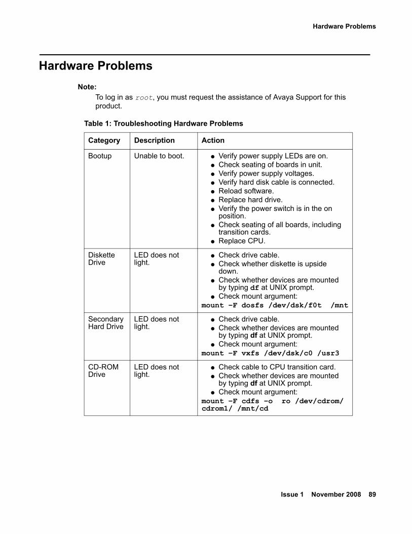
Hardware Problems
Issue 1 November 2008 89
Hardware Problems Note:
Note: To log in as root, you must request the assistance of Avaya Support for this product.
Table 1: Troubleshooting Hardware Problems
Category Description Action
Bootup Unable to boot. ● Verify power supply LEDs are on.● Check seating of boards in unit.● Verify power supply voltages.● Verify hard disk cable is connected.● Reload software.● Replace hard drive.● Verify the power switch is in the on
position.● Check seating of all boards, including
transition cards.● Replace CPU.
Diskette Drive
LED does not light.
● Check drive cable.● Check whether diskette is upside
down.● Check whether devices are mounted
by typing df at UNIX prompt.● Check mount argument:
mount –F dosfs /dev/dsk/f0t /mnt
Secondary Hard Drive
LED does not light.
● Check drive cable.● Check whether devices are mounted
by typing df at UNIX prompt.● Check mount argument:
mount –F vxfs /dev/dsk/c0 /usr3
CD-ROM Drive
LED does not light.
● Check cable to CPU transition card.● Check whether devices are mounted
by typing df at UNIX prompt.● Check mount argument:
mount –F cdfs –o ro /dev/cdrom/cdrom1/ /mnt/cd
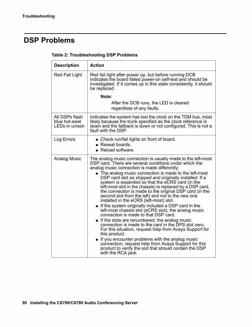
Troubleshooting
90 Installing the CS700/CS780 Audio Conferencing Server
DSP Problems
Table 2: Troubleshooting DSP Problems
Description Action
Red Fail Light Red fail light after power up, but before running DCB indicates the board failed power-on self-test and should be investigated. If it comes up in this state consistently, it should be replaced.
Note:Note: After the DCB runs, the LED is cleared
regardless of any faults.
All DSPs flash blue hot-swat LEDs in unison
Indicates the system has lost the clock on the TDM bus, most likely because the trunk specified as the clock reference is down and the fallback is down or not configured. This is not a fault with the DSP.
Log Errors ● Check run/fail lights on front of board.● Reseat boards.● Reload software.
Analog Music The analog music connection is usually made to the left-most DSP card. There are several conditions under which the analog music connection is made differently:
● The analog music connection is made to the left-most DSP card slot as shipped and originally installed. If a system is expanded so that the eCRS card (in the left-most slot in the chassis) is replaced by a DSP card, the connection is made to the original DSP card (in the second slot from the left) and not to the new one installed in the eCRS (left-most) slot.
● If the system originally included a DSP card in the left-most chassis slot (eCRS slot), the analog music connection is made to that DSP card.
● If the slots are renumbered, the analog music connection is made to the card in the DPS slot zero. For this situation, request help from Avaya Support for this product.
● If you encounter problems with the analog music connection, request help from Avaya Support for this product to verify the slot that should contain the DSP with the RCA jack.
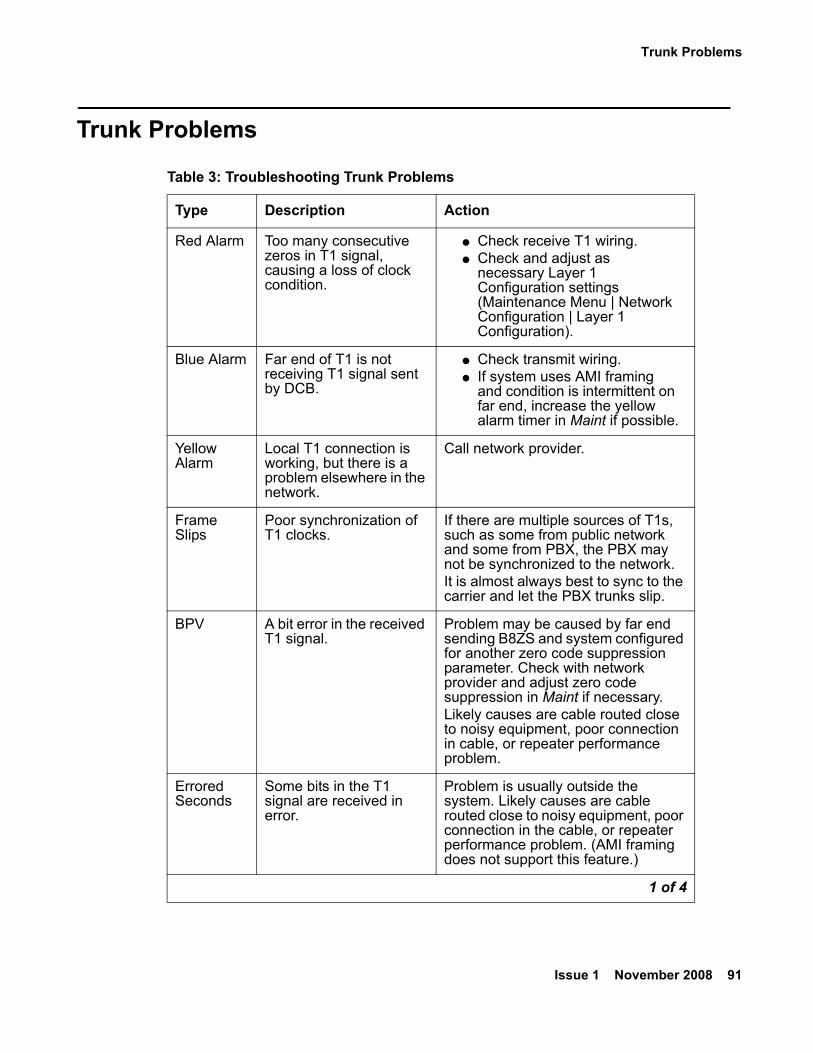
Trunk Problems
Issue 1 November 2008 91
Trunk Problems
Table 3: Troubleshooting Trunk Problems
Type Description Action
Red Alarm Too many consecutive zeros in T1 signal, causing a loss of clock condition.
● Check receive T1 wiring.● Check and adjust as
necessary Layer 1 Configuration settings (Maintenance Menu | Network Configuration | Layer 1 Configuration).
Blue Alarm Far end of T1 is not receiving T1 signal sent by DCB.
● Check transmit wiring.● If system uses AMI framing
and condition is intermittent on far end, increase the yellow alarm timer in Maint if possible.
Yellow Alarm
Local T1 connection is working, but there is a problem elsewhere in the network.
Call network provider.
Frame Slips
Poor synchronization of T1 clocks.
If there are multiple sources of T1s, such as some from public network and some from PBX, the PBX may not be synchronized to the network.It is almost always best to sync to the carrier and let the PBX trunks slip.
BPV A bit error in the received T1 signal.
Problem may be caused by far end sending B8ZS and system configured for another zero code suppression parameter. Check with network provider and adjust zero code suppression in Maint if necessary.Likely causes are cable routed close to noisy equipment, poor connection in cable, or repeater performance problem.
Errored Seconds
Some bits in the T1 signal are received in error.
Problem is usually outside the system. Likely causes are cable routed close to noisy equipment, poor connection in the cable, or repeater performance problem. (AMI framing does not support this feature.)
1 of 4
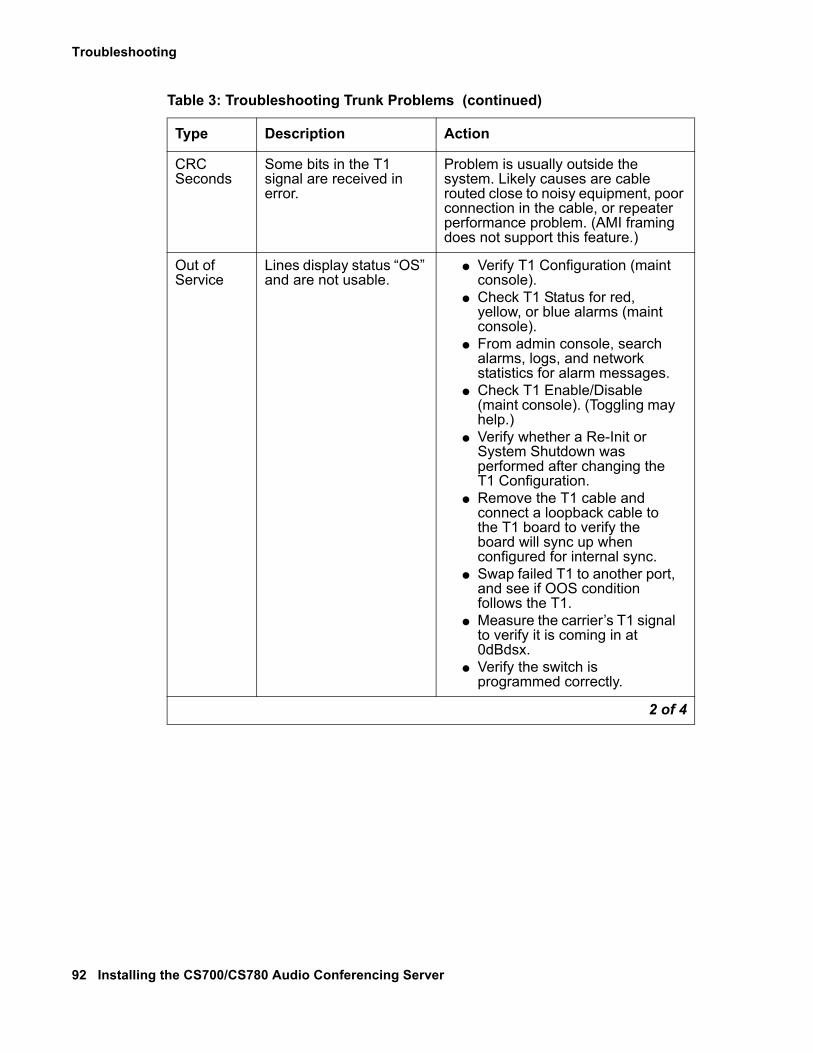
Troubleshooting
92 Installing the CS700/CS780 Audio Conferencing Server
CRC Seconds
Some bits in the T1 signal are received in error.
Problem is usually outside the system. Likely causes are cable routed close to noisy equipment, poor connection in the cable, or repeater performance problem. (AMI framing does not support this feature.)
Out of Service
Lines display status “OS” and are not usable.
● Verify T1 Configuration (maint console).
● Check T1 Status for red, yellow, or blue alarms (maint console).
● From admin console, search alarms, logs, and network statistics for alarm messages.
● Check T1 Enable/Disable (maint console). (Toggling may help.)
● Verify whether a Re-Init or System Shutdown was performed after changing the T1 Configuration.
● Remove the T1 cable and connect a loopback cable to the T1 board to verify the board will sync up when configured for internal sync.
● Swap failed T1 to another port, and see if OOS condition follows the T1.
● Measure the carrier’s T1 signal to verify it is coming in at 0dBdsx.
● Verify the switch is programmed correctly.
Table 3: Troubleshooting Trunk Problems (continued)
Type Description Action
2 of 4
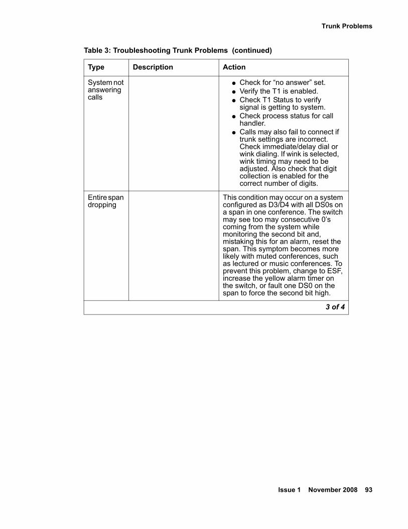
Trunk Problems
Issue 1 November 2008 93
System not answering calls
● Check for “no answer” set.● Verify the T1 is enabled.● Check T1 Status to verify
signal is getting to system.● Check process status for call
handler.● Calls may also fail to connect if
trunk settings are incorrect. Check immediate/delay dial or wink dialing. If wink is selected, wink timing may need to be adjusted. Also check that digit collection is enabled for the correct number of digits.
Entire span dropping
This condition may occur on a system configured as D3/D4 with all DS0s on a span in one conference. The switch may see too may consecutive 0’s coming from the system while monitoring the second bit and, mistaking this for an alarm, reset the span. This symptom becomes more likely with muted conferences, such as lectured or music conferences. To prevent this problem, change to ESF, increase the yellow alarm timer on the switch, or fault one DS0 on the span to force the second bit high.
Table 3: Troubleshooting Trunk Problems (continued)
Type Description Action
3 of 4
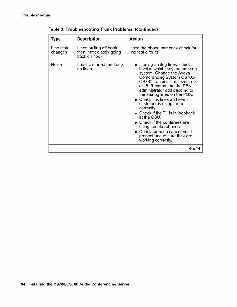
Troubleshooting
94 Installing the CS700/CS780 Audio Conferencing Server
Line state changes
Lines pulling off hook then immediately going back on hook.
Have the phone company check for line test circuits.
Noise Loud, distorted feedback on lines.
● If using analog lines, check level at which they are entering system. Change the Avaya Conferencing System CS700/CS780 transmission level to -3 or -6. Recommend the PBX administrator add padding to the analog lines on the PBX.
● Check link lines and see if customer is using them correctly.
● Check if the T1 is in loopback at the CSU.
● Check if the conferees are using speakerphones.
● Check for echo cancelers; if present, make sure they are working correctly.
Table 3: Troubleshooting Trunk Problems (continued)
Type Description Action
4 of 4
LAN Problems
Issue 1 November 2008 95
LAN ProblemsIf the LAN configuration process fails, or the system is not able to communicate after network installation, it is necessary to troubleshoot the LAN. The problem is most likely with the network connection.
If link integrity has been established and the system still does not communicate on the LAN, the problem may be an incorrect configuration in the network software.
The CPU card has LEDs that indicate LAN status. The steady green LED at the connector indicates the link passed integrity test, and the blinking green LED at the connector indicates receive/transmit activity.
Check TCP/IP Settings
Note:Note: To login as root, you must request the assistance of Avaya Support for this
product.
Check the system’s TCP/IP settings if you cannot successfully ping another device on the network from the system:
1. Log in as root.
2. Open scoadmin.
scoadmin
3. Select Networking | Network Configuration Manager.4. Select TCP/IP.
5. Select View Protocol.6. Check current settings for customer IP information. Make sure the settings are correct.
Troubleshooting
96 Installing the CS700/CS780 Audio Conferencing Server
Check the Internet Services Daemon (inetd) and Network Files
Note:Note: To login as root, you must request the assistance of Avaya Support for this
product.
To check the Internet services daemon (inetd) and network files, follow these steps:
1. Log in as root.
2. Determine whether or not the inetd process is running as it should be.
ps -ef | grep inetd
3. Check the integrity of the following network files if TCP/IP settings are correct and you still cannot successfully ping another device on the network from the system:
● /etc/resolv.conf (should list DNS server name(s))
● /etc/confnet.d/inet/interface (should include system TCP/IP configuration parameters)
● /etc/inet/config (includes a list of network services on the system)
● /etc/inet/hosts (include system host and perhaps remote host names)
● /etc/inet/nb.conf (defines which IP interfaces on this system that NetBIOS will run over)
● /usr/ns-home/admserv/ns-admin.conf
● /etc/inet/named.d/db.local (local loopback interface file)
Issue 1 November 2008 97
Index
Index
AAdding Cards . . . . . . . . . . . . . . . . . . . 75Adding T1/E1/ISDN Cards
CS700 . . . . . . . . . . . . . . . . . . . . . 81CS780 . . . . . . . . . . . . . . . . . . . . . 82
Adding T3 CardsCS700 . . . . . . . . . . . . . . . . . . . . . 83
Alarm RelayConnections . . . . . . . . . . . . . . . . . . 64Contact Configuration . . . . . . . . . . . . . . 65Terminal Block Configuration . . . . . . . . . . 65
Analog Audio Interface . . . . . . . . . . . . . . . 15Analog Music Connection . . . . . . . . . . . . . 61
Special Considerations . . . . . . . . . . . . . 85Application Servers
AC Power Connections . . . . . . . . . . . . . 47Installing . . . . . . . . . . . . . . . . . . . . 41Maintenance Modem . . . . . . . . . . . . . . 54
BBootup problems. . . . . . . . . . . . . . . . . . 89
CCabling
LAN . . . . . . . . . . . . . . . . . . . . . . 25Network . . . . . . . . . . . . . . . . . . . . 26
Call Processing Components . . . . . . . . . . . . .11Capacity
CS700 . . . . . . . . . . . . . . . . . . . . . 29CS780 . . . . . . . . . . . . . . . . . . . . . 29
Card LayoutCS700 T1/E1/ISDN System . . . . . . . . . . . 33CS700 T3 System . . . . . . . . . . . . . . . 34CS780 T1/E1/ISDN System . . . . . . . . . . . 35
Card Swapping . . . . . . . . . . . . . . . . . . 67Category 5 UTP . . . . . . . . . . . . . . . . . . 25CD/Floppy Drive, Replacing . . . . . . . . . . . . 78CD-ROM Drive Problems. . . . . . . . . . . . . . 89Central Processing Unit Card (CPU) . . . . . . . . 12Chassis Installation, CS700/CS780 . . . . . . . . . 29Client Registration Server . . . . . . . . . . 10, 12, 23Conventions . . . . . . . . . . . . . . . . . . . . . 8CPU Cards
Identifying . . . . . . . . . . . . . . . . . . . 76Outdated . . . . . . . . . . . . . . . . . . . . 76
CS700AC Power. . . . . . . . . . . . . . . . . . . . 19AC Power Connections . . . . . . . . . . . . . 41Adding T1/E1/ISDN Cards . . . . . . . . . . . . 81Adding T3 Cards . . . . . . . . . . . . . . . . 83Capacity . . . . . . . . . . . . . . . . . . . . 29DC Power. . . . . . . . . . . . . . . . . . . . 20DC Power Connections . . . . . . . . . . . . . 42Grounding . . . . . . . . . . . . . . . . . 20, 43Mixed T1/E1/ISDN and T3 . . . . . . . . . . . . 35Power and Cooling Requirements . . . . . . . . 19T1/E1/ISDN System, Card Layout . . . . 33, 34, 35Thermal Dissipation . . . . . . . . . . . . . . . 19
CS700/CS780Chassis Installation . . . . . . . . . . . . . . . 29Maintenance Modem . . . . . . . . . . . . . . 52
CS780AC Power. . . . . . . . . . . . . . . . . . . . 21AC Power Connections . . . . . . . . . . . . . 44Adding T1/E1/ISDN Cards . . . . . . . . . . . . 82Capacity . . . . . . . . . . . . . . . . . . . . 29DC Power. . . . . . . . . . . . . . . . . . . . 21DC Power Connections . . . . . . . . . . . . . 45Grounding . . . . . . . . . . . . . . . . . 22, 45Thermal Dissipation . . . . . . . . . . . . . . . 20
CS780 Power and Cooling Requirements . . . . . . 20CSU . . . . . . . . . . . . . . . . . . . . . . . . 26
DDell Poweredge 1850 . . . . . . . . . . . . . . . . 23Dell Poweredge 2850 . . . . . . . . . . . . . . . . 23Digital Signal Processors (DSP) . . . . . . . . . . . 11Diskette Drive Problems . . . . . . . . . . . . . . 89Dot Hill RAID
AC Power. . . . . . . . . . . . . . . . . . . . 22AC Power Connections . . . . . . . . . . . . . 46DC Power. . . . . . . . . . . . . . . . . . . . 22DC Power Connections . . . . . . . . . . . . . 47Description . . . . . . . . . . . . . . . . . . . 22Installing . . . . . . . . . . . . . . . . . . . . 36Thermal Dissipation . . . . . . . . . . . . . . . 22
DSP CardsInstalling . . . . . . . . . . . . . . . . . . . . 84Required for T3 . . . . . . . . . . . . . . . . . 34Troubleshooting . . . . . . . . . . . . . . . . . 90
98 Installing the CS700/CS780 Audio Conferencing Server
Index
EeCRS . . . . . . . . . . . . . . . . . . . . . .10, 12Electrostatic discharge precautions . . . . . . . . . 27Embedded CRS
Maintenance Modem . . . . . . . . . . . . . . 54Environmental Requirements
Humidity . . . . . . . . . . . . . . . . . . . . 18Temperature . . . . . . . . . . . . . . . . . . 18Vibration . . . . . . . . . . . . . . . . . . . . 18
GGrounding
CS700 . . . . . . . . . . . . . . . . . . . . . 43CS780 . . . . . . . . . . . . . . . . . . . . . 45
HHardware
troubleshooting . . . . . . . . . . . . . . . . . 89Humidity, Environmental Requirement. . . . . . . . 18
IIdentifying Components . . . . . . . . . . . . . . 16Identifying Outdated Equipment. . . . . . . . . . . 75Installation
CS700/CS780 . . . . . . . . . . . . . . . . . 29Installation Requirements. . . . . . . . . . . . . . 27installed boards . . . . . . . . . . . . . . . . . . 16Installing
Application Servers . . . . . . . . . . . . . . . 41Cards . . . . . . . . . . . . . . . . . . . . . 73KVM Switch . . . . . . . . . . . . . . . . . . 41
InterfaceLAN . . . . . . . . . . . . . . . . . . . . . . 88local maintenance port . . . . . . . . . . . . . 88T3 . . . . . . . . . . . . . . . . . . . . . . . 88trunk . . . . . . . . . . . . . . . . . . . . . . 87
KKeyboard/Video/Mouse (KVM) Switch . . . . . . .10, 48KVM Switch
AC Power Connections . . . . . . . . . . . . . 45Installing . . . . . . . . . . . . . . . . . . . . 41
LLAN
Cabling . . . . . . . . . . . . . . . . . . . . 25T3 Cards . . . . . . . . . . . . . . . . . . . . 60
troubleshooting . . . . . . . . . . . . . . . . . 95LAN Connections. . . . . . . . . . . . . . . . 14, 55Lan Connections
T1 Systems CPU Card (Alternate) . . . . . . . . 56T1 Systems CPU Card (Normal) . . . . . . . . . 56T1 Systems eCRS Card . . . . . . . . . . . . . 58T3 Systems . . . . . . . . . . . . . . . . . . . 58
MMaintenance Modem . . . . . . . . . . . . . . . . 23
AC Power Connections . . . . . . . . . . . . . 47Application Servers . . . . . . . . . . . . . . . 54CS700.CS780. . . . . . . . . . . . . . . . . . 52Embedded CRS. . . . . . . . . . . . . . . . . 54
Modem Connections . . . . . . . . . . . . . . . . 14Mounting Options. . . . . . . . . . . . . . . . . . 17
NNetwork Cabling . . . . . . . . . . . . . . . . . . 26
T1/E1/ISDN . . . . . . . . . . . . . . . . . . . 26T3 . . . . . . . . . . . . . . . . . . . . . . . 26
Network Connections . . . . . . . . . . . . . . . . 13T1/E1/ISDN . . . . . . . . . . . . . . . . . . . 62
Network Interface Card (NIC) . . . . . . . . . . . . 11Installing . . . . . . . . . . . . . . . . . . . . 84
Network Traffic . . . . . . . . . . . . . . . . . . . 25
OOperating Conditions . . . . . . . . . . . . . . . . 18Outdated Equipment, Identifying. . . . . . . . . . . 75Overview. . . . . . . . . . . . . . . . . . . . . . 10
PPower . . . . . . . . . . . . . . . . . . . . . . . 13
CS700 AC System . . . . . . . . . . . . . . . 19CS700 DC System . . . . . . . . . . . . . . . 20CS700 Grounding . . . . . . . . . . . . . . . . 20CS780 AC System . . . . . . . . . . . . . . . 21CS780 DC System . . . . . . . . . . . . . . . 21CS780 Grounding . . . . . . . . . . . . . . . . 22Dot Hill RAID AC System . . . . . . . . . . . . 22Dot Hill RAID DC System . . . . . . . . . . . . 22
Power and Cooling RequirementsCS700 . . . . . . . . . . . . . . . . . . . . . 19CS780 . . . . . . . . . . . . . . . . . . . . . 20
Power ConnectionsApplication Servers AC . . . . . . . . . . . . . 47CS700 AC . . . . . . . . . . . . . . . . . . . 41CS700 DC . . . . . . . . . . . . . . . . . . . 42CS780 AC . . . . . . . . . . . . . . . . . . . 44
Issue 1 November 2008 99
Index
CS780 DC . . . . . . . . . . . . . . . . . . . 45Dot Hill RAID AC . . . . . . . . . . . . . . . . 46Dot Hill RAID DC . . . . . . . . . . . . . . . . 47KVM Switch AC . . . . . . . . . . . . . . . . 45Maintenance Modem AC . . . . . . . . . . . . 47
Power Up and Initial Testing . . . . . . . . . . . . 66Power Up Sequence . . . . . . . . . . . . . . . . 66Problems
Bootup . . . . . . . . . . . . . . . . . . . . . 89CD-ROM Drive . . . . . . . . . . . . . . . . . 89Diskette Drive . . . . . . . . . . . . . . . . . 89Secondary Hard Drive . . . . . . . . . . . . . 89
RRack Mount . . . . . . . . . . . . . . . . . . . . 17RAID Connection . . . . . . . . . . . . . . . . . 49
Dual CPU . . . . . . . . . . . . . . . . . . . 51Single CPU. . . . . . . . . . . . . . . . . . . 51
Related Documentation . . . . . . . . . . . . . . . 9Replacing Cards . . . . . . . . . . . . . . . . .73, 74
SS780 Hardware Requiements. . . . . . . . . . . . .11S780 Platform . . . . . . . . . . . . . . . . . . . 20Scoadmin . . . . . . . . . . . . . . . . . . . .66, 95Secondary Hard Drive Problems . . . . . . . . . . 89Server
Client Registration . . . . . . . . . . . . 10, 12, 23Web Conferencing Server . . . . . . . . . . . . 23Web Portal . . . . . . . . . . . . . . . . . . . 23
Setting IP AddressApplication Servers . . . . . . . . . . . . . . . 66CS700/CS780 CPU. . . . . . . . . . . . . . . 66
Setting IP Addresses. . . . . . . . . . . . . . . . 66Shutting Down the System . . . . . . . . . . . . . 73Site Requirements . . . . . . . . . . . . . . . . . 28Site Survey . . . . . . . . . . . . . . . . . . . . 13Swapping Cards
Hot Swap DSP . . . . . . . . . . . . . . . . . 69Hot Swap T1/E1/PRI NIC . . . . . . . . . . . . 70Normal Shutdown. . . . . . . . . . . . . . . . 67System Failure . . . . . . . . . . . . . . . . . 68
System Clean Up and Labeling . . . . . . . . . . . 72
TT1/E1/ISDN Network Cabling . . . . . . . . . . . . 26T1/E1/ISDN Network Connections . . . . . . . . . 62T1/E1/PRI NIC Cards, Idenfitying . . . . . . . . . . 80T3 Cards
Description . . . . . . . . . . . . . . . . . . . 12Setting Up for LAN . . . . . . . . . . . . . . . 60
T3 Network Cabling. . . . . . . . . . . . . . . . . 26Temperature, Environmental Requirement . . . . . . 18Thermal Dissipation
CS700 . . . . . . . . . . . . . . . . . . . . . 19CS780 . . . . . . . . . . . . . . . . . . . . . 20Dot Hill RAID . . . . . . . . . . . . . . . . . . 22
Time Domain Multiplexed (TMD) bus . . . . . . . . 11Tools and Materials. . . . . . . . . . . . . . . . . 28transition cards . . . . . . . . . . . . . . . 33, 34, 36Troubleshooting . . . . . . . . . . . . . . . . . . 87
checking TCP/IP settings . . . . . . . . . . . . 95DSP Problems . . . . . . . . . . . . . . . . . 90DSP problems . . . . . . . . . . . . . . . . . 90Hardware . . . . . . . . . . . . . . . . . . . . 89hardware problems . . . . . . . . . . . . . . . 89LAN . . . . . . . . . . . . . . . . . . . . . . 95LAN problems. . . . . . . . . . . . . . . . . . 95T1 problems . . . . . . . . . . . . . . . . . . 91trunk problems . . . . . . . . . . . . . . . . . 91Trunk Span . . . . . . . . . . . . . . . . . . . 93
UUpdating Hardware . . . . . . . . . . . . . . . . . 73
VVibration, Environmental Requirement . . . . . . . . 18
WWeb Conferencing Server . . . . . . . . . . . . . . 23Web Portal Server . . . . . . . . . . . . . . . . . 23Windows 2003 Server . . . . . . . . . . . . . . . 23

100 Installing the CS700/CS780 Audio Conferencing Server
Index


