61
802.3bn Link Ad Hoc Meeting Notes & Baseline

802.3bn Link Ad Hoc
Meeting Notes & Baseline

Agenda, Notes – 4/3/13• Conference Call at 11am‐12 PDT
• IEEE Patent Policy Reviewed
• Attendance Taken – See slide
• Editor for PLC– Marek will put into PCS (the framing)– Saif and Joe for PMD
• Downstream Command Format Proposal from Broadcom/Huawei.
• Review baseline proposal and questions
2IEEE 802.3bn EPoC – Link Ad Hoc

Agenda, Notes – 3/27/13• Conference Call at 11am‐12
• IEEE Patent Policy Reviewed
• Attendance Taken – See slide
• Review Straw polls and Motions from Orlando
• Review start of baseline proposal and questions
3IEEE 802.3bn EPoC – Link Ad Hoc

Agenda, Notes – 3/20/13• At IEEE Plenary in Orlando• PHY Link Channel – Avi Kliger, Nicola Varanese• PHY Config Switchover – Ed Boyd• Straw polls passed without time for motion
– EPoC must support hitless switchover for certain PHY configuration (e.g. Bit loading, Nulling)
– The PLC should include a Configuration ID for hitless switchover
• Motion Passed: – The downstream PHY Link shall include an error correcting code.– The Downstream PLC will be 400KHz wide without continuous pilots. 8 subcarriers at
50KHz spacing or 16 subcarriers at 25KHz spacing.– The PLC will be transparent to the MAC.
• No Additional Jitter and latency• No additional Buffering
– The Downstream PHY Link Channel shall be composed of a preamble (with start of frame delimiter) and PLC frame. It will not include MAC Data. Note: Guard time or dead‐time may also be included.
4IEEE 802.3bn EPoC – Link Ad Hoc

Agenda, Notes – 3/6/13• Conference Call at 11am‐12
• IEEE Patent Policy Reviewed
• Attendance Taken – See slide
• Presentation on Downstream Synchronization (part 2) – Duane Remein
• PLC Forward Error Correction – Avi
• Updated Simulation Results ‐ Nicola
5IEEE 802.3bn EPoC – Link Ad Hoc

PATENTSIEEE Patent Policy
IEEE 802.3bn EPoC – Link Ad Hoc 6

4/3/2013 Slide 77

4/3/2013 Slide 88

4/3/2013 Slide 99

4/3/2013 Slide 1010

4/3/2013 Slide 1111

ATTENDEES
IEEE 802.3bn EPoC – Link Ad Hoc 12

Attendance – 4/3/13 Conf Call• Ed Boyd, Broadcom• Leo Montreuil, Broadcom• Hesham ElBakoury, Huawei• Bill Keasler, Ikanos• Marek Hajduczenia, ZTE• Avi Kliger, Broadcom• Saif Rahman, Comcast• George Hart, Rogers• Joe Solomon, Comcast• Christian Pietsch, Qualcomm• Nicola Varanese, Qualcomm• Syed Rahman, Huawei
13IEEE 802.3bn EPoC – Link Ad Hoc

Attendance – 3/27/13 Conf Call• Ed Boyd, Broadcom• Duane Remein, Huawei• Steve Shellhammer, Qualcomm• Bill Powell, ALU• Mark Laubach, Broadcom• Hesham ElBakoury, Huawei• Bill Keasler, Ikanos• Marek Hajduczenia, ZTE• Avi Kliger, Broadcom• Syed Rahman, Huawei• Tom Staniec, Cohere• George Hart, Rogers
14IEEE 802.3bn EPoC – Link Ad Hoc

Attendance – 3/6/13 Conf Call• Ed Boyd, Broadcom• Marek Hajduczenia, ZTE• Alan Brown, Aurora• Curtis Knittle, CableLabs• Joe Solomon, Comcast• Duane Remein, Huawei• Bill Powell, ALU• Christian Pietsch, Qualcomm• Nicola Varanese, Qualcomm• Avi Klinger, Broadcom• Hesham ElBakoury, Huawei• Steve Shellhammer, Qualcomm• Syed Rahman, Huawei• Jim Farmer, Aurora• Tom Staniec, Cohere• George Hart, Rogers
15IEEE 802.3bn EPoC – Link Ad Hoc

OVERVIEW & TOPICS
16
Overview
• Objective– Define the process for the CLT PHY to connect to CNU PHY before the MAC is
enabled.– Define any re‐negotiation or PHY parameter procedure.– Define the PHY parameters to be configured over MDIO & Auto‐Negotiation– What happens after CLT PHY & CNU PHY power up?– What parameters are PHY? (others are MAC)
• Output of the Ad Hoc– Baseline proposal
• A single agreed solution is best.• Two or more options with pros and cons is the other option.
– Joint Presentation for next meeting
17IEEE 802.3bn EPoC – Link Ad Hoc

Link Topics• Link Transport Methods
– Upstream– Downstream– e.g. Time Inserted or Frequency Inserted, or other – Protocol
• Auto‐negotiation‐Link state machine– Finding the Downstream– Speeding up the process– Initial Upstream
• Message Format & Addressing– e.g. Address + Register Pages
• Protocol– Dynamic or Static: Master or Slave, who makes change– e.g. Echo Protocol
• Parameters and Status Indicators• MAC Discovery Compatibility
18IEEE 802.3bn EPoC – Link Ad Hoc

Parameters & Status IndicatorsSystem Wide Possible• TDD or FDD• Power management control• Note: Probing of the entire data channel would be handled in the MAC channel and not PHY link channelDownstream Definition Possible List• Number of Downstream OFDM channels• 192MHz OFDM Channels Characteristics
– Center Frequency, Cyclic Prefix, FEC, Interleaver type/depth, symbol length• 192MHz OFDM Channels: Available Sub‐Carrier (Frequency allocation) • 192MHz OFDM Channels: Sub‐Carrier Modulation OrderUpstream Definition Possible List• Upstream PHY Link Channel frequency• Number of Upstream OFDM channels• 192MHz OFDM Channels Characteristics
– Center Frequency, Cyclic Prefix, FEC, Interleaver type/depth, symbol length• 192MHz OFDM Channels: Available Sub‐Carrier (Frequency allocation) • 192MHz OFDM Channels: Sub‐Carrier Modulation Order• Transmit Power Level• Transmit OffsetDoes not carry MAC Layer or above Frames (Configuration for upper layers could be carried)
19IEEE 802.3bn EPoC – Link Ad Hoc

Start Up Time Budget• Finding the Downstream Channel
– Hunt frequency and find preamble(Estimate at 2 seconds)
• Configuration for Downstream MAC channel– 1 second to transfer sub‐carrier configuration
20IEEE 802.3bn EPoC – Link Ad Hoc

Evaluation Criteria• Link establishment time.• Simplicity• Must work all of the time• Must work below the MAC• Bandwidth used
21IEEE 802.3bn EPoC – Link Ad Hoc

Definitions• PLC – PHY Link Channel
22IEEE 802.3bn EPoC – Link Ad Hoc

LINK TRANSPORT
IEEE 802.3bn EPoC – Link Ad Hoc 23

Link Transport Notes• How many CNUs are supported?
– In general, this is a design specification issue but we need to size fields.– Fields should be 15 bits to match LLID size.– Practical Numbers for analysis: 256 CNU PHYs per CLT PHY. (8 LLIDs per CNU, what does really mean to the PHY?)
• Do we need a Link configuration on the CLT PHY for every CNU PHY?– Some parameters will be common but others will be unique.– If we have to specify transmit power, delay offset, etc; they would be unique.
• How fast does it need to be? What is the data rate?• How is the initial contention handled?
– Broadcom Proposal: Random Symbol Offset or backoff a number of slot opportunities
• Do we need to detect collisions or just provide avoidance?– Broadcom Proposal: Avoidance
• How do we find the initial downstream channel?– Broadcom Proposal: Stored from previous position. Hunt based on 6MHz and/or 8MHz center frequencies.
• Do we need to acknowledge information from CLT PHY to CNU PHY?• How fast do things change in the Network?
– Updates in minutes.
24IEEE 802.3bn EPoC – Link Ad Hoc

Link Transport Notes• How do we handle ingress noise on PHY link channel?
– Double the channel– Move the channel– Avoid placing it on top of ingress, use clean spectrum, low modulation order. Only move if required.
• Do we define a grid position for the PHY link channel to simplify searching?– One location in a 24MHz channel? (Centered or first carriers or last carriers?)– One location in 6MHz and/or 8MHz channel grid? (Centered or first carriers or last carriers?)– One location in 2MHz channel grid? (Centered or first carriers or last carriers?)
• How do we transport multiple profile configurations if needed?– Option 1: Carry base profile in PHY link channel and bring up MAC with it. Use OAM to configure additional profiles.– Option 2: Configure all profiles in the PHY link channel.
25IEEE 802.3bn EPoC – Link Ad Hoc
Link Transport – Downstream Channel• How many PHY link channels do you need in the downstream?
– 1 per 192 MHz– 1 for entire downstream
• How much data is needed in the channel?• How much preamble is needed in the channel?
– 1 symbol might work with auto‐correlation– 2 symbols is simpler– 8 symbols is easy to find
• We need to define a fixed pattern (preamble) in the downstream PHY link channel– Can we use a CP instead of a preamble?– Fixed period?
26IEEE 802.3bn EPoC – Link Ad Hoc

Link Transport – Downstream Data Rate• Determine the required rate
– Guessing the bandwidth of configuration of the modulation [channel worst case]• 4 channels (of 192MHz) x 16K carriers per block x byte per carrier = 64K Bytes• If initial configuration time of 1 second is required, then 64K Bytes needs 512Kbps• Double this so 1Mbps.
• 1Mbps @ 16QAM is 256KHz – without overhead, 5 carriers at 4K FFT, 50KHz– 1% at 24MHz
• Duane to expand on the analysis
27IEEE 802.3bn EPoC – Link Ad Hoc
Link Transport – # of Channels– Do we want 1 PHY link of 1Mbps per 192 MHz channel downstream?
• Is it a unique channel or just a duplicate if isolated channels? • Option 1: downstream is unique per 192MHz but upstream information would be the
same if sharing the same upstream channel. All center Freq of downstream 192MHz blocks
• Option 2: Duplicate entire PHY link so a multiple channel only needs to listen to 1 for all information
• Option 3: Single PHY Link channel. Any lower capabilities CNU must listen to common channel that carries the PHY Link channel.
• The decision for 1 per 192MHz or 1 per downstream can be linked to the decision on required CNU channel support. The PLC must follow this decision.
– Do we want 1 PHY link of ?Mbps per ? MHz channel upstream?• For TDD, upstream and downstream channel count would likely be the same.• Multiple PHY Link channels will use 2 transmitters out of the limit• Number of transmitters limit will grow as channel size increases?
28IEEE 802.3bn EPoC – Link Ad Hoc

Downstream PHY Link Channel• Number of preambles of symbols?
– Fixed pattern, BPSK, PN sequence is an example– 2 symbols is used in LTE– 2 maybe difficult to detect in bad SNR, 8 would be able to support bad SNR– Avi simulation results show 8 symbols has high detection rate– Avi will show presentation on results at the next meeting
• How often should preamble be repeated?– Every 128 symbols, 8 preamble symbols (1/16th of PHY link channel) [Avi]
29IEEE 802.3bn EPoC – Link Ad Hoc

Downstream PHY Link Channel• Cycle Size of PLC
– Could be a configured size. – The maximum period will be defined so the searching time is known– The minimum period will be related to the frame alignment indication
• PLC preamble start relative to data channel frame alignment indication– The PLC position could be used to identify a known position in the downstream
cycle for TDD.– In FDD, the PLC position could be aligned with pilot rotation
30IEEE 802.3bn EPoC – Link Ad Hoc

Upstream PHY Link Channel• PHY Link upstream
– Narrow Channel– Sets the symbol boundary: Timing advance
• How do we send on all upstream carriers so we can “tune” the upstream?– Tuning is modulation selection, phase, amplitude, power– Tuning is a burst of pilots– Fixed cycle in the PHY – option 1– MAC triggered event – option 2
• What should the MAC send and should it be put on the wire?• Would it make sense to send the FEC block?
31IEEE 802.3bn EPoC – Link Ad Hoc

BASELINE PROPOSALPHY Link Channel
IEEE 802.3bn EPoC – Link Ad Hoc 32

Overview• Objective
– The PHY Link Channel (PLC) provides a physical layer management path for configuration and status monitoring outside of MAC layer (MPCP) messages or OAM messages.
– The PLC can be used before or after MAC layer registration to communicate with a remote PHY.
– The PLC allows for adapting the PHY configuration to coax conditions.
– The PLC allows for hitless configuration switch over. (SP#10)– The PLC allows for feature detection and negotiation of features between the CLT PHY and CNU PHY.
33IEEE 802.3bn EPoC – Link Ad Hoc
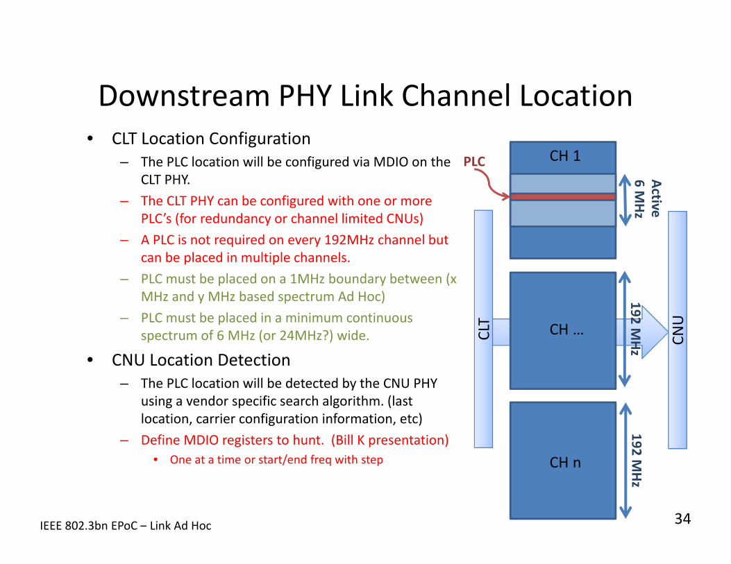
Downstream PHY Link Channel Location• CLT Location Configuration
– The PLC location will be configured via MDIO on the CLT PHY.
– The CLT PHY can be configured with one or more PLC’s (for redundancy or channel limited CNUs)
– A PLC is not required on every 192MHz channel but can be placed in multiple channels.
– PLC must be placed on a 1MHz boundary between (x MHz and y MHz based spectrum Ad Hoc)
– PLC must be placed in a minimum continuous spectrum of 6 MHz (or 24MHz?) wide.
• CNU Location Detection– The PLC location will be detected by the CNU PHY
using a vendor specific search algorithm. (last location, carrier configuration information, etc)
– Define MDIO registers to hunt. (Bill K presentation)• One at a time or start/end freq with step
34IEEE 802.3bn EPoC – Link Ad Hoc
CLT
CLT
CNU
CNU
192 MHz
192 MHz
6 MHz
PLC
Active
CH 1
CH …
CH n
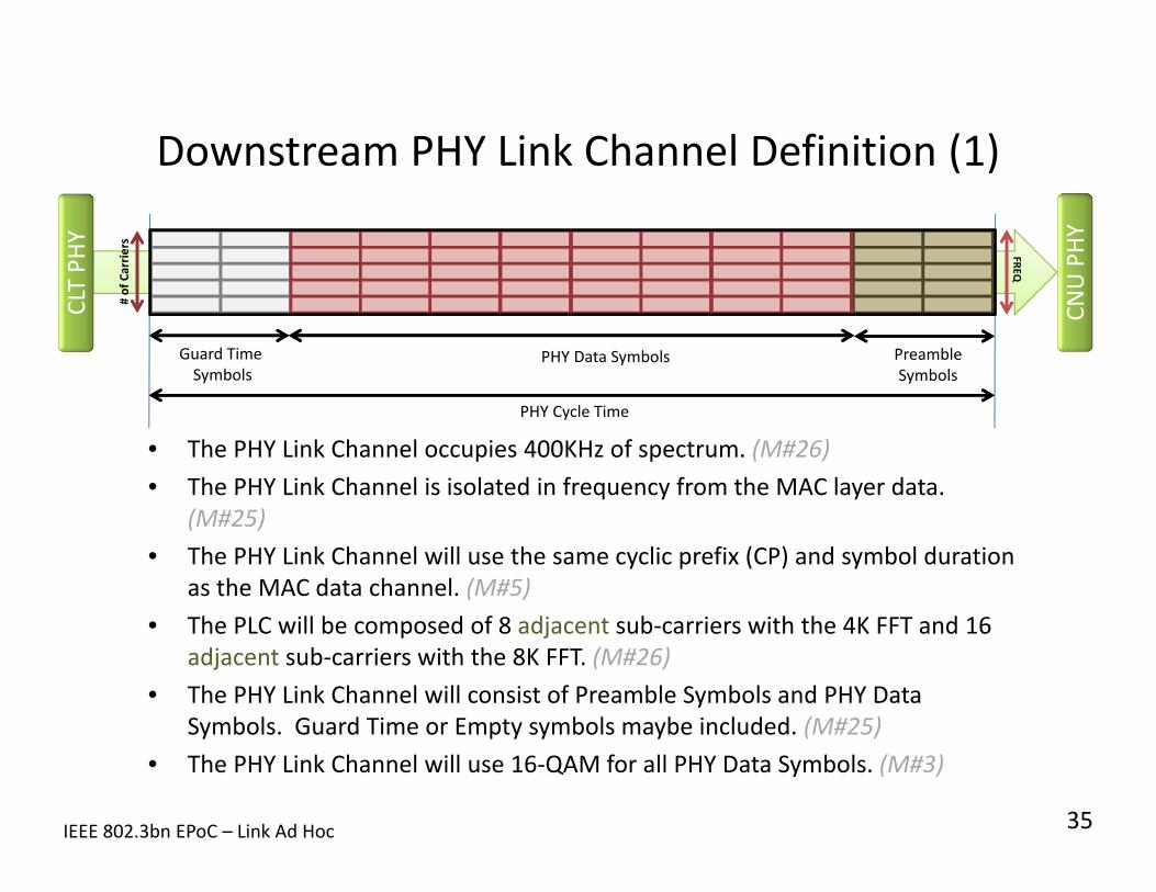
Downstream PHY Link Channel Definition (1)
• The PHY Link Channel occupies 400KHz of spectrum. (M#26)• The PHY Link Channel is isolated in frequency from the MAC layer data.
(M#25)• The PHY Link Channel will use the same cyclic prefix (CP) and symbol duration
as the MAC data channel. (M#5)• The PLC will be composed of 8 adjacent sub‐carriers with the 4K FFT and 16
adjacent sub‐carriers with the 8K FFT. (M#26)• The PHY Link Channel will consist of Preamble Symbols and PHY Data
Symbols. Guard Time or Empty symbols maybe included. (M#25)• The PHY Link Channel will use 16‐QAM for all PHY Data Symbols. (M#3)
IEEE 802.3bn EPoC – Link Ad Hoc
CLT PH
Y
CNU PHY
PHY Data Symbols PreambleSymbols
Guard TimeSymbols
# of Carrie
rsFREQ
PHY Cycle Time
35

Downstream PHY Link Channel Definition (2)
• The PHY Link Channel will be a repeated cycle.• The PHY Cycle time will be aligned with the MAC data channel.
– In TDD mode, the PHY Cycle Time will be time aligned with the TDD Cycle Time.– In FDD mode, the PHY Cycle Time will be time aligned with the staggered pilot
pattern.– The minimum PHY Cycle Time will be TBD – The maximum PHY Cycle Time will be TBD
• The PHY Link Channel will contain 8 Preamble Symbols with a fixed pattern of TBD
• The PLC will contain a fixed/configurable number of ??? data carrying symbols.
IEEE 802.3bn EPoC – Link Ad Hoc
CLT PH
Y
CNU PHY
PHY Data Symbols PreambleSymbols
Guard TimeSymbols
# of Carrie
rsFREQ
PHY Cycle Time
36

Downstream PHY Link Channel
37IEEE 802.3bn EPoC – Link Ad Hoc
FDD TDD
PHY Link Channel Width(# of Carriers x carrier width)
400KHz: 16x25KHz or 8x50KHz 400KHz: 16x25KHz or 8x50KHz
Guard Time/Symbols 0 to 0
Preamble Symbols 8 8
PHY Data Symbols ???? ????
PHY Cycle Time 128x20us???
CLT PH
Y
CNU PHY
PHY Data Symbols PreambleSymbols
Guard TimeSymbols
# of Carrie
rsFREQ
PHY Cycle Time

PHY Link Frame (Downstream)
38IEEE 802.3bn EPoC – Link Ad Hoc
MDIOADDR (16)
CNU PHYAddress(48)
Write Instruction
CLT PH
Y
CNU PHYPHY
Config ID(2 bits)
MDIODATA (16)
MDIOCMD (2)
MDIOADDR(16)
Read Instruction
MDIOCMD(2)
FEC(?)
Padding(0‐?)
• The PHY Link Frame will be a fixed number of bytes.• PHY Link Frame will contain a 48‐bit PHY Destination Address.
– The MAC Address of the CNU can be used as a PHY address.– CNU PHYs will receive instructions from the Broadcast Address or Unicast Address.
• The PHY Link Frame will contain a 2‐bit PHY Configuration Identifier to allow for hitless switchover of select PHY configurations. (SP#10‐11)
• The PHY Link Frame will contain one or more instructions to a remote PHY’s registers.
– Write MDIO Address– Write/Read MDIO Address– Read MDIO Address
• The PHY Link Frame will contain forward error correction. (M#23)• ??? Code will be used.
Fixed # of Bytes or variable size?

STRAW POLLSPHY Link Channel
IEEE 802.3bn EPoC – Link Ad Hoc 39

Straw Poll #1• Should the downstream PHY link channel be a fixed modulation order (e.g.
QPSK, 16QAM, 64QAM)?
• Y: 27• N: 1• Abstain: 7
40IEEE 802.3bn EPoC – Link Ad Hoc
November 2012 – Conference Call
Straw Poll #2• The PHY Link Channel should use 16QAM Modulation order?
• Y: 11• N: 0• Abstain: 0
41IEEE 802.3bn EPoC – Link Ad Hoc
December 2012 – Conference Call

Straw Poll #3• The PHY Link Channel should use the same CP size and symbol duration as
the data channel?
• Y: 11 • N: 0 • Abstain: 0
42IEEE 802.3bn EPoC – Link Ad Hoc January 2013 – Phoenix Meeting

Straw Poll #4• A CNU will auto‐detect the CP size and sub‐carrier spacing (symbol
duration) of the downstream PHY Link Channel [Not provisioned at CNU]
• Y: 12• N: 0• Abstain: 0
43IEEE 802.3bn EPoC – Link Ad Hoc
January 2013 – Phoenix Meeting

Straw Poll #5• The downstream PHY link channel should be a dedicated set of carriers in
every downstream symbol (isolated from MAC data).
• Y: 13• N: 0• Abstain: 8
44IEEE 802.3bn EPoC – Link Ad Hoc
January 2013 – Phoenix Meeting

Straw Poll #6PHY‐Link register
I think that the read/write capability of all/nearly all CNU PHY registers should be the same between the PHY‐Link (from CLT) and MDIO (from CNU)
Yes __4___No, some _____No, None __1___Abstain __ 3 ___
IEEE 802.3bn EPoC – Link Ad Hoc January 2013 – Phoenix Meeting
45

Straw Poll #7
The downstream PHY Link should include an error correcting code or error checking code?
Error Correcting _25____Error checking Code _4____Nothing _0____Abstain _7____
IEEE 802.3bn EPoC – Link Ad Hoc March 2013 – Orlando Meeting
46

Straw Poll #8
The PLC is transparent to the MAC.No Additional Jitter and latencyNo additional Buffering
Yes _36_No _0__Abstain _2__
IEEE 802.3bn EPoC – Link Ad Hoc March 2013 – Orlando Meeting
47

Straw Poll #9
The Downstream PHY Link Channel shall be composed of a preamble (with start of frame delimiter) and PLC frame. It will not include MAC Data. Note: Guard time or dead‐time may also be included.
Yes _23_No _0_Abstain _10_
IEEE 802.3bn EPoC – Link Ad Hoc March 2013 – Orlando Meeting
48
Straw Poll #10
49
• EPoC must support hitless switchover for certain PHY configuration (e.g. Bit loading, Nulling)?
• Yes: 32• No: 0• Abstain: 1
March 2013 – Orlando Meeting
IEEE 802.3bn EPoC – Link Ad Hoc

Straw Poll #11
50
• The PLC should include a Configuration ID for hitless switchover?
• Yes: 31• No: 0• Abstain: 3
March 2013 – Orlando Meeting
IEEE 802.3bn EPoC – Link Ad Hoc

MOTIONSPHY Link Channel
IEEE 802.3bn EPoC – Link Ad Hoc 51

Motion #3• The Downstream PHY Link Channel shall use a fixed modulation order of 16
QAM to carry PHY link information.
• Mover: Ed Boyd• Seconder: Kevin Noll
• Y: 39• N: 0• Abstain: 0
• Technical Motion >=75%
52IEEE 802.3bn EPoC – Link Ad Hoc
January 2013 – Phoenix Meeting

Motion #4• A CNU shall auto‐detect the CP size and sub‐carrier spacing of the
downstream PHY Link Channel
• Y: 40• N: 0• Abstain: 0
• Mover: Ed Boyd• Seconder: Juan Montojo
• Technical Motion >=75%
53IEEE 802.3bn EPoC – Link Ad Hoc
January 2013 – Phoenix Meeting

Motion #5• The Downstream PHY Link Channel shall use the same CP size and symbol
duration as the data channel.
• Y: 42• N: 0• Abstain: 0
• Mover: Ed Boyd• Seconder: Eugene Dai
• Technical Motion >=75%
54IEEE 802.3bn EPoC – Link Ad Hoc
January 2013 – Phoenix Meeting

Motion #23
The downstream PHY Link shall include an error correcting code.
Mover: Juan MontojoSeconder: Kevin Noll
Yes __37___No __1___Abstain __4___
Technical Motion >=75%
IEEE 802.3bn EPoC – Link Ad Hoc March 2013 – Orlando Meeting
55

Motion #24The PLC will be transparent to the MAC.
No Additional Jitter and latencyNo additional Buffering
Mover: Sanjay KasturiaSeconder: Avi Kliger
Yes __39_No __0_Abstain __2_
Technical Motion >=75%
IEEE 802.3bn EPoC – Link Ad Hoc March 2013 – Orlando Meeting
56

Motion #25The Downstream PHY Link Channel shall be composed of a preamble (with start of
frame delimiter) and PLC frame. It will not include MAC Data. Note: Guard time or dead‐time may also be included.
Mover: Juan MontojoSeconder: Ed Boyd
Yes _40__No _0__Abstain _1__
Technical Motion >=75%
March 2013 – Orlando Meeting
March 2013 – Orlando MeetingIEEE 802.3bn EPoC – Link Ad Hoc 57

Motion #26
The Downstream PLC will be 400KHz wide without continuous pilots. 8 subcarriers at 50KHz spacing or 16 subcarriers at 25KHz spacing.
Mover: Nicola VaraneseSeconder: Avi Kliger
Yes _31_No _1__Abstain _10__Technical Motion >=75%
IEEE 802.3bn EPoC – Link Ad Hoc March 2013 – Orlando Meeting
58

REFERENCE MATERIALSEarlier Presentations on Link
IEEE 802.3bn EPoC – Link Ad Hoc 59

DOWNSTREAM COMMAND FORMAT PROPOSAL
PHY Link ChannelEd Boyd, Hesham ElBakoury, Duane Remein
IEEE 802.3bn EPoC – Link Ad Hoc 60

PHY Register Instruction
Downstream PHY Register Instruction
61IEEE 802.3bn EPoC – Link Ad Hoc
CNU PHYAddress(48 bits)
PHY Register Instruction
CLT PH
Y
CNU PHYPHY
Config ID(2 bits)
FEC(? bits)
Padding(0‐?)
• A PLC frame will contain 1 or more PHY Register Instructions.• The PHY Register Instruction is variable length based on the OPCODE used.• OPCODEs support reading and writing MDIO addresses. • The write/read verify command allows for an acknowledged write. • Up to 32 consecutive addresses can be configured or read with a single command.
– Example for writing 8 addresses in the PHY• With Consecutive Address: Opcode (1B) + Address (2B) + 8xWriteData(2B) = 19 Bytes• Without Consecutive Address: [Opcode (1B) + Address (2B) + WriteData(2B)]x8 = 40 Bytes
PHY Register
Instruction
PHY Register Instruction
OPCODE(8 bits)
ADDRESS(16 bits)
WRITE DATA(16 bits)
WRITE DATA(16 bits)
WRITE DATA(16 bits)
OPCODE
Count(5 bits)
CMD(3 bits)
CMD0 – NOP1 – Read2 – Write3 – Write/Read Verify4‐7 ‐ Reserved
CMD0 – NOP1 – Read2 – Write3 – Write/Read Verify4‐7 ‐ Reserved
CountNumber of consecutive addressesplus 1 to perform a command
CountNumber of consecutive addressesplus 1 to perform a command
One or More Variable Size Instructions


