51
Meeting Report of the Joint IPCC/TEAP Expert Meeting on Options for the Limitation of Emissions of HFCs and PFCs Petten, The Netherlands 26-28 May 1999
| Date post: | 21-Nov-2018 |
| Category: |
Documents |
| Upload: | truongkhanh |
| View: | 231 times |
| Download: | 0 times |

Meeting Report
of the
Joint IPCC/TEAP Expert Meeting on
Options for the Limitation of Emissions of
HFCs and PFCs
Petten, The Netherlands26-28 May 1999
2 ECN-RX--99-029
DISCLAIMER
IPCC co-sponsorship does not imply IPCC endorsement or approval of these proceedings or anyrecommendations or conclusions contained herein. Neither the papers presented at the work-shop/ meeting/seminar nor the report of its proceedings have been subjected to IPCC review.
The United Nations Environment Programme (UNEP), the Technology and Economic Assess-ment Panel (TEAP) co-chairs and members, and the companies and organisations that employthem do not endorse the performance, worker safety, or environmental acceptability of any ofthe technical options discussed. Moreover, as work continues - including additional toxicityevaluation - more information on health, environmental and safety effects of alternatives andreplacements will become available for use in selecting among the options discussed in thisdocument. UNEP, the TEAP co-chairs and members, in furnishing or distributing the informa-tion that follows, do not make any warranty or representation, either express or implied, withrespect to the accuracy, completeness, or utility; nor do they assume any liability of any kindwhatsoever resulting from the use or reliance upon any information, material, or procedurecontained herein.
The IPCC/TEAP Joint Expert Meeting and the publication of the Meeting Report and the Tech-nical Papers has been sponsored by
The Netherlands Ministry of Environment (VROM)United States Environmental Protection Agency (USEPA)
The text of this Meeting Report is composed in Times New Roman.
Co-ordination: Lambert Kuijpers (TEAP) and Remko Ybema (IPCC)
Composition / Layout: Lambert Kuijpers
Reproduction: printed in the Netherlands by theEnergy Research Foundation, Petten, the Netherlandsand by theUNFCCC Secretariat for the SBSTA-11 meeting
Date: 15 July 1999
No copyright involved. This publication or a part of it may be freely copied, abstracted andcited, with acknowledgement of the source of the material.
ECN-RX--99-029 3
CONTENTS
1. INTRODUCTION 51.1 Background 51.2 Interrelations 51.3 Joint Expert Meeting Organisation 61.4 Montreal and Kyoto Protocols linked via the atmosphere 71.5 Structure of the report 8
2. PAST, CURRENT AND PROJECTED CONSUMPTION AND EMISSIONS 92.1 Introduction 92.2 Past and current consumption 92.3 Projected Long Term Consumption and Emissions 12
3. WORKING GROUP FINDINGS 153.1 Refrigeration and Air Conditioning 15
3.1.1 Stationary Sources 153.1.2 Mobile Sources 16
3.2 Foams 173.3 Aerosol Products 20
3.3.1 Non-Medical Uses 203.3.2 Medical Uses - MDIs 20
3.4 Industrial and PFC and SF6 Emissions 213.5 Solvents 223.6 Fire Extinguishants 233.7 Developing Country Aspects 23
4. CONCLUDING REMARKS 26
REFERENCES 30
ANNEX A REFRIGERATION AND AIR CONDITIONING 31
ANNEX B FOAMS 33
ANNEX C AEROSOL PRODUCTS 35
ANNEX D INDUSTRIAL AND PFC AND SF6 EMISSIONS 37
ANNEX E SOLVENTS 41
ANNEX F FIRE EXTINGUISHANTS 42
ANNEX G ACRONYMS 43
ANNEX H LIST OF PARTICIPANTS (NAME, AFFILIATION, COUNTRY) 44
ANNEX I TABLE OF CONTENTS OF THE PROCEEDINGSPAPERS PRESENTED 48

4 ECN-RX--99-029
ECN-RX--99-029 5
REPORT OF‘THE JOINT IPCC/TEAP EXPERT MEETING ON OPTIONS FOR
THE LIMITATION OF EMISSIONS OF HFCs AND PFCs’
1. INTRODUCTION
1.1 Background
This meeting report presents the major findings and discussions from the Expert Meeting on‘Options for the Limitation of Emissions of HFCs and PFCs’ jointly sponsored by the IPCCWorking Group III and the Technology and Economic Assessment Panel (TEAP) of the Mont-real Protocol (referred to in this document as the ‘Joint Expert Meeting’).
In 1998, developing countries expressed concern that actions taken under the Kyoto Protocol tocontrol HFCs and PFCs could have implications for their development process. Manufacturersof products that use or might use HFCs and PFCs also sought clarification. It is for this reasonthat Sri Lanka tabled a proposal at the Open Ended Working Group (OEWG) meeting under theMontreal Protocol in Geneva, June 1998. Two decisions were taken on the issue of limitation ofHFC and PFC emissions, one decision was adopted by the Parties to the UNFCCC, and at their10th Meeting in Cairo, the Parties to the Montreal Protocol adopted a complementary decision.
In November 1998, the 4th Conference of the Parties to the UNFCCC adopted a decision (Deci-sion 13/CP.4, document FCCC/CP/16/Add.1), which invited organisations, including the rele-vant bodies of the Montreal Protocol, ‘…to provide information by July 15, 1999….’, and en-couraged ‘the convening of a workshop by the IPCC and the Technology and Economic As-sessment Panel of the Montreal Protocol in 1999 which will assist SBSTA to establish informa-tion on available and potential ways and means of limiting emissions of hydrofluorocarbons andperfluorocarbons…’. In November 1998, the Parties to the Montreal Protocol adopted a deci-sion in which they requested the TEAP (in Decision X/16) to provide such information to theUNFCCC and to assess the implications to the Montreal Protocol of the inclusion of HFCs andPFCs in the Kyoto Protocol and to report these findings to the Eleventh Meeting of the Partiesto the Montreal Protocol. In addition, the Parties to the Montreal Protocol also encouraged theIPCC and TEAP to jointly convene a workshop on ‘available and potential ways and means’ oflimiting emissions of HFCs and PFCs. The Technical Support Unit of the IPCC WGIII and theTEAP took the responsibility for co-organising the Joint Expert Meeting.
1.2 Interrelations
Parties to the UNFCCC and Parties under the Montreal Protocol took similar decisions becausethe issues of ozone depletion and climate change are scientifically and ‘technically’ interrelated.They are scientifically interrelated because changes in ozone affect the Earth’s climate andchanges in temperature, greenhouse gases and climate affect the ozone layer (see section 1.4).The Montreal and Kyoto Protocols are ‘technically’ interrelated because HFCs included in thebasket of gases of the Kyoto Protocol are significant substitutes for some ozone depleting sub-stances (ODSs) controlled under the Montreal Protocol. CO2, CH4, N2O, PFCs, and SF6 are allincluded in the basket of gases of the Kyoto Protocol. Of these, CO2 has been proposed as a po-tentially significant substitute to ODSs and HFCs used as refrigerants and blowing agents. The
6 ECN-RX--99-029
other gases are insignificant substitutes to ODSs. The above requests by the UNFCCC/SBSTAand the Montreal Protocol suggest that it is important that strategies and technologies be devel-oped that address both climate and ozone protection, and that actions be taken in a manner thatpromotes sustainable development in developing countries.
The issue of energy efficiency is of crucial importance in relation to indirect global warmingimpacts arising from CO2 emissions arising from energy production. Using a non-HFC sub-stance or technology avoids any emission, however, may significantly influence energy usage.In some cases the effect can be beneficial. However, in other situations there is an energy pen-alty, which can actually lead to an increase in CO2 emissions that outweigh the benefits of re-duced HFC emissions. These effects are strongly application- and design-dependent and mustbe carefully taken into account when considering HFC emission reduction strategies.
1.3 Joint Expert Meeting Organisation
During January-April 1999 the Joint Expert Meeting was organised by a local organising com-mittee chaired by Lambert Kuijpers (TEAP) and Remko Ybema (IPCC) working with a techni-cal advisory committee consisting of 12 members with IPCC or TEAP background, and mem-bers of the Ozone and UNFCCC Secretariats1. It sent out invitations to broad groups of techni-cal experts, identified via IPCC and TEAP lists of experts. Every organisation requesting par-ticipation was allowed at least one registration but governments and industry organisations wereasked to limit participation to two experts. Environmental NGOs were also invited and in somecases expenses were funded out of the Joint Expert Meeting budget.
The Joint Expert Meeting was held at ECN Petten, The Netherlands, 26 – 28 May 1999. It wasattended by approximately 100 participants from 24 countries (Australia, Austria, Belgium,Canada, Denmark, Finland, France, Germany, India, Japan, Kenya, Malaysia, Mexico, Nether-lands, Poland, Sri Lanka, Sierra Leone, Sweden, Switzerland, Thailand, Uruguay, UK, USA,and Vietnam)2. Ten participants were from developing countries and Countries with Economiesin Transition (CEIT)3. A list giving the names and affiliations of all the participants is given inAnnex 8.
Participants represented the European Commission; ministries of environment, fisheries, trans-portation, industry and foreign affairs; technical, chemical, and research institutions, universi-ties, and consulting organisations; industry associations and environmental organisations;fluorocarbon, hydrocarbon, foam and speciality chemical suppliers; the Global EnvironmentFacility (GEF); UNEP Montreal Protocol Multilateral Fund Secretariat, the UNEP TEAP and itsTechnical Options Committees and Task Forces; the UNFCCC Secretariat; the Ozone Secretar-iat; the IPCC; UNEP Technology, Industry and Economics (TIE), UNDP, and UNIDO; andautomobile, foam, refrigerator, refrigeration, air conditioning, fire protection, electronics indus-tries and electric utility companies.
Funding for the Joint Expert Meeting was received from both the Netherlands Ministry forHousing, Spatial Planning and the Environment and the US Environmental Protection Agency.
1 Members of the technical advisory committee were Stephen O. Andersen, USA (TEAP), Paul Ashford, UK
(TEAP), Kornelis Blok, Netherlands (IPCC), Suely M. Carvalho, Brazil (TEAP), Ogunlade Davidson, Sierra Leone(IPCC), Sukumar Devotta, India (TEAP/TOC), Barbara Kuznerowicz-Polak, Poland (TEAP) , Mack McFarland,USA (IPCC), William R. Moomaw, USA (IPCC), Ramon Pichs-Madruga, Cuba (IPCC), K. Madhava Sarma(Ozone Secretariat), Dennis Tirpak (UNFCCC Secretariat), and Lambert Kuijpers and Remko Ybema.
2 One environmental NGO wishes to register its concerns about the potential bias of the HFC review process at theJoint Expert Meeting due to its perceived over-representation of the fluorocarbon industry and related corporate in-dustries at the Joint Expert Meeting and wishes to note that it is of the opinion that the organisers of the meetingcould not ensure sufficient participation of experts from not-in-kind industries.
3 One environmental NGO wishes to register that stronger efforts must be made to include developing countries inthis process.
ECN-RX--99-029 7
The Joint Expert Meeting was co-chaired by Ogunlade Davidson, co-chair IPCC WGIII, andLambert Kuijpers, co-chair TEAP. The meeting consisted of one day of plenary presentationsby experts from both developed and developing countries. The plenary also heard presentationsfrom three environmental NGOs. Subsequently, experts from various application sectors metseparately in working group meetings during two days, followed by a concluding plenary dis-cussion. The working groups were asked to list and prioritise options to limit emissions, tocatalogue opportunities and barriers, and to give estimates for future emissions under differentscenarios4. The meeting concluded with plenary presentations of summaries of the workinggroup discussions and by four government representatives. The government representatives de-scribed approaches being taken by Denmark, Germany, Japan and the USA to limit emissions ofHFCs and PFCs.
The drafting committee for the meeting report consisted of Ogunlade Davidson (IPCC), StephenO. Andersen (TEAP), Ray Gluckman, Jochen Harnisch, Mack McFarland (IPCC), William R.Moomaw (IPCC), Suely M. Carvalho (TEAP), Lambert Kuijpers (TEAP) and Remko Ybema(IPCC). After that a zero order draft had been developed, it was sent out to the full TechnicalAdvisory Committee for comments. A first order draft was then developed which was sent outto all the participants for review. Thirty-five review reactions were received, at a total of aboutseventy pages. These review comments were included after careful study, whether it concernednecessary additions for clarity, issues discussed at the meeting, etc. The last draft of the meetingreport was again sent to the Technical Advisory Committee for final comments, after which itwas despatched to the UNFCCC secretariat, as was requested in the relevant decisions.
Lambert Kuijpers and Remko Ybema chaired the local organising committee, co-ordinated thedifferent stages in the drafting and review process of the meeting report and were involved inthe assembly of the papers presented at the Joint Expert Meeting.
1.4 Montreal and Kyoto Protocols linked via the atmosphere
The Joint Expert Meeting started with a presentation on the linkage between the Montreal andthe Kyoto Protocol by one of the co-chairs of the Montreal Protocol Science Assessment Panel/Meg99/. A summary is given below.
The issues of ozone depletion and global climate change are linked through physical and chemi-cal processes in the atmosphere. Gases controlled under the Montreal Protocol contribute to theEarth’s radiation balance, gases that could be controlled under the Kyoto Protocol affect theozone layer, and climate change can have an influence on the ozone layer. Most of the ozonedepleting substances (ODSs) are also significant greenhouse gases, and increases in their at-mospheric concentrations tend to have a warming effect on the Earth’s surface. At the sametime, because stratospheric ozone also plays a role in the radiation balance of the atmosphere,ozone depletion caused by increasing concentrations of ODSs tends to have a cooling effect onthe Earth’s surface. Therefore, the net climate effect of an individual ODS depends on its directglobal warming potential relative to its ozone depleting potential.
Nitrous oxide and methane, two gases that could be controlled under the Kyoto Protocol, havedirect effects on global atmospheric chemistry that can influence ozone depletion. Increasingconcentrations of these gases have multiple effects on stratospheric chemistry including interac-tions with the ozone destruction cycles of chlorine and bromine carried to the stratosphere byODSs. Methane concentrations also affect global tropospheric chemistry and, hence, atmos-
4 Two environmental NGOs wish to have their concerns highlighted in this meeting report in relation to the approach
followed at the Joint Expert Meeting. In their opinion, HFCs and PFCs are not necessary and therefore the limita-tion of emissions of fluorocarbon substances should have been explored only after that alternative technologies andsubstances would have been thoroughly discussed. They expressed deep regret that the thrust of the discussion andreport reviewing process has been the other way around, implying that HFCs and PFCs are necessary.
8 ECN-RX--99-029
pheric lifetimes of those ODSs that contain hydrogen atoms (e.g., HCFCs, HFCs, methyl chlo-roform, methyl bromide) and hence are removed in the troposphere. In addition, stratosphericozone depletion allows greater amounts of UV-B solar radiation to reach the troposphere. In-creased amounts of UV-B also affect atmospheric chemistry and can shorten the lifetimes ofthose ODSs containing hydrogen.
Global climate change is expected to shift air circulation patterns and alter the temperaturestructure of the atmosphere. In particular, the addition of CO2 to the atmosphere has lead to anadditional cooling of the stratosphere, which in turn causes extra ozone loss from chlorine andbromine containing ODSs. Current understanding of all these chemical and physical changessuggests that recovery of the ozone layer could be delayed. In other words, recovery could beslower than one would anticipate based on projected declines in the amounts of chlorine andbromine in the stratosphere alone. More information on these effects can be found in the mostrecent scientific assessment conducted under the Montreal Protocol: ‘Scientific Assessment ofOzone Depletion: 1998’ /Sci98/.
1.5 Structure of the report
This report is divided into five sections. The first section provides background material. Thesecond covers current uses of HFC, PFC and SF6 chemicals and projected consumption andemissions as presented in plenary and working group sessions during the Joint Expert Meeting.Working group discussions are summarised in the third section. Background information on theissues discussed is summarised, areas of convergence and divergence are highlighted and majorfindings are listed. The overall outcome and a list of issues that need additional study are pre-sented in the fourth - conclusions - section. Additional material from the working group sessionsis presented in Annexes. Papers presented at the meeting are provided in a separate volume (theTable of Contents of this volume can be found in Annex I).
ECN-RX--99-029 9
2. PAST, CURRENT AND PROJECTED CONSUMPTION ANDEMISSIONS
2.1 Introduction
Unlike the case for most greenhouse gas emissions where release to the atmosphere occurs atthe time of production of the gas (e.g. carbon dioxide is emitted to the atmosphere when it isformed in the combustion of fossil fuels), HFCs and PFCs are often stored in equipment andproducts for many years after they are produced and sold into the market. However, as soon asthe products are used, HFC and PFC emissions start to occur. The timing of large scale emis-sions, comparable to product inventory, varies from less than a year for applications such as useas an aerosol propellant, to over a decade for some refrigeration applications, to many decadesfor some insulating foam applications. Both consumption and emission estimates are presentedin this report and the reader is cautioned not to confuse the two.
HFC, PFC and SF6 emission scenarios are usually developed using:- Historic production and consumption data.- Assumptions on the difference between production and consumption (substances may be
stored for a certain time before they are consumed).- Forecast for future production and consumption based upon GDP, population and usage
growth.- Substitution of CFCs and HCFCs with certain HFCs and other alternatives.- Estimates of the time dependent release from different types of applications (which includes
assumptions on leakage).- Assumptions on the results of technological change in the absence of climate policies.
Estimates of the time dependent release from certain applications, as well as of the sort term de-velopment of end user markets and technological changes, already yield uncertainties in the cur-rent and near future emission levels. Furthermore, when comparing emission scenarios basedupon these types of data and estimates for the long term (i.e., a period of 50-100 years) it is verylikely that one will conclude substantial differences in the forecast of emissions by different ex-perts. Several papers presented at the Joint Expert Meeting /Fen99, Glu99, Joh99, McC99/ showthese large differences, as well as smaller differences for the shorter term. It should thereforeemphasised that one should not focus too much on the differences; the purpose of the Joint Ex-pert Meeting has not been directed towards a determination of the most appropriate and ade-quate ways to judge the value of emission scenarios. This will ask for a substantial amount ofwork within a different framework in the near future.
2.2 Past and current consumption
The current generation of HFCs were introduced in the early 1990’s as substitutes for CFCswith almost no use before 1990. The only significant emissions of HFCs before 1990 resultedfrom production of HFC-23 as a byproduct of the production of HCFC-22. Thus, HFC emis-sions grew from a very small, although important base if considered on a basis of global warm-ing (since it concerned mainly emissions of HFC-23, a very potent greenhouse gas). The emis-sion levels of HFCs in the year 1997 were approximately 55 ktonnes (this comprised 43 ktonnesof HFC-134a /AFE99/, 7 ktonnes of HFC-23 estimated by certain experts /Ora98, Mid93/ andby AFEAS /AFE99/ from HCFC-22 production data, and 5 ktonnes of HFC-152a.
10 ECN-RX--99-029
The main sources of PFC emissions (from aluminium smelting and from the electronics indus-try) were already established by 1990. Few reliable publications on world-wide PFC and SF6
emission data for 1997 or 1998 can be found /Har99, Mai98/; certain individual countries (suchas the UK and the USA) have recently published well researched data.
The main uses of HFCs in the 1990’s are in the refrigeration and (mobile) air conditioning sec-tors (80-90%). Growing markets that are expected to be significant by 2008 include MeteredDose Inhalers (MDIs), insulating foam and possibly aerosol products. Global production of allHFCs (mainly HFC-134a) has increased by a factor of five between 1993 and 1998, from about25 ktonnes in 1993 to 120 ktonnes in 1998, according to figures published recently /TEA98/.
Production and consumption of CFCs and halons was phased out in developed countries in lessthan a decade through use of a variety of alternative chemical substances, technologies andpractices. However, the total production and consumption of CFCs and halons (and some otherODSs) in the developing countries will not be phased out until 2010; these efforts are largelysupported by the Montreal Protocol Multilateral Fund. Furthermore, a phaseout of productionand consumption does not automatically mean a phaseout of all uses. Numerous refrigerationequipment (e.g. domestic refrigerators) is still in use and could emit to the environment if notadequately recovered at disposal. Many chillers operated using CFCs are still in use in the de-veloped and developing countries, and it will take substantial amount of time before these haveall been retrofitted or replaced.
0
400
800
1200
1600
1980 1981 1982 1983 1984 1985 1986 1987 1988 1989 1990 1991 1992 1993 1994 1995 1996 1997
CFCs HALONS HCFCs HFCs
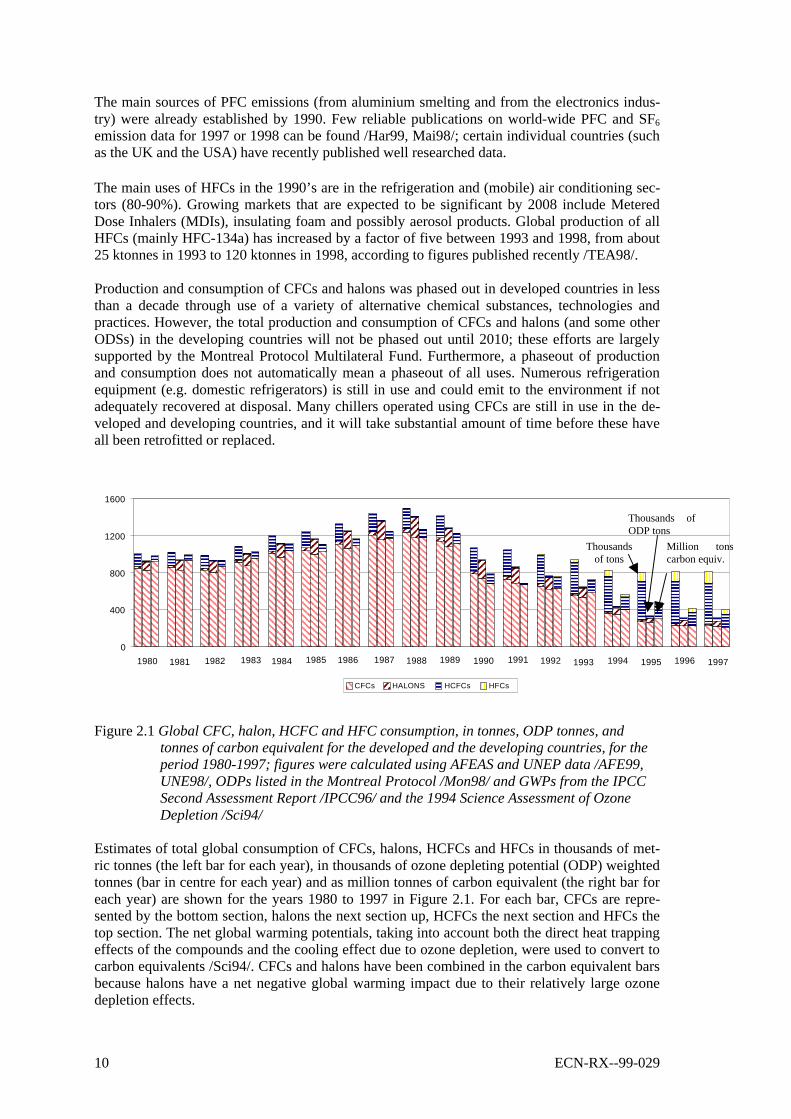
Figure 2.1 Global CFC, halon, HCFC and HFC consumption, in tonnes, ODP tonnes, andtonnes of carbon equivalent for the developed and the developing countries, for theperiod 1980-1997; figures were calculated using AFEAS and UNEP data /AFE99,UNE98/, ODPs listed in the Montreal Protocol /Mon98/ and GWPs from the IPCCSecond Assessment Report /IPCC96/ and the 1994 Science Assessment of OzoneDepletion /Sci94/
Estimates of total global consumption of CFCs, halons, HCFCs and HFCs in thousands of met-ric tonnes (the left bar for each year), in thousands of ozone depleting potential (ODP) weightedtonnes (bar in centre for each year) and as million tonnes of carbon equivalent (the right bar foreach year) are shown for the years 1980 to 1997 in Figure 2.1. For each bar, CFCs are repre-sented by the bottom section, halons the next section up, HCFCs the next section and HFCs thetop section. The net global warming potentials, taking into account both the direct heat trappingeffects of the compounds and the cooling effect due to ozone depletion, were used to convert tocarbon equivalents /Sci94/. CFCs and halons have been combined in the carbon equivalent barsbecause halons have a net negative global warming impact due to their relatively large ozonedepletion effects.
Thousandsof tons
Thousands ofODP tons
Million tonscarbon equiv.
ECN-RX--99-029 11
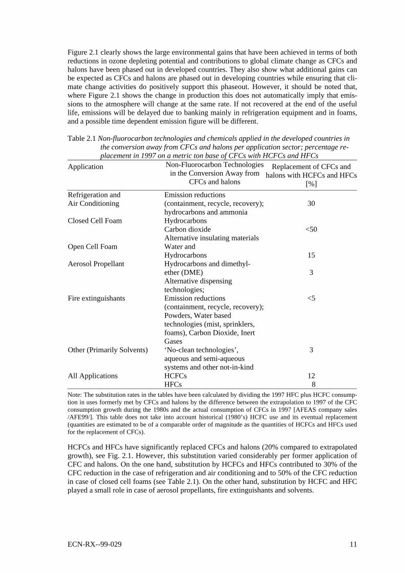
Figure 2.1 clearly shows the large environmental gains that have been achieved in terms of bothreductions in ozone depleting potential and contributions to global climate change as CFCs andhalons have been phased out in developed countries. They also show what additional gains canbe expected as CFCs and halons are phased out in developing countries while ensuring that cli-mate change activities do positively support this phaseout. However, it should be noted that,where Figure 2.1 shows the change in production this does not automatically imply that emis-sions to the atmosphere will change at the same rate. If not recovered at the end of the usefullife, emissions will be delayed due to banking mainly in refrigeration equipment and in foams,and a possible time dependent emission figure will be different.
Table 2.1 Non-fluorocarbon technologies and chemicals applied in the developed countries inthe conversion away from CFCs and halons per application sector; percentage re-placement in 1997 on a metric ton base of CFCs with HCFCs and HFCs
Application Non-Fluorocarbon Technologiesin the Conversion Away from
CFCs and halons
Replacement of CFCs andhalons with HCFCs and HFCs
[%]
Refrigeration andAir Conditioning
Emission reductions(containment, recycle, recovery);hydrocarbons and ammonia
30
Closed Cell Foam HydrocarbonsCarbon dioxideAlternative insulating materials
<50
Open Cell Foam Water andHydrocarbons 15
Aerosol Propellant Hydrocarbons and dimethyl-ether (DME)Alternative dispensingtechnologies;
3
Fire extinguishants Emission reductions(containment, recycle, recovery);Powders, Water basedtechnologies (mist, sprinklers,foams), Carbon Dioxide, InertGases
<5
Other (Primarily Solvents) ‘No-clean technologies’,aqueous and semi-aqueoussystems and other not-in-kind
3
All Applications HCFCsHFCs
128
Note: The substitution rates in the tables have been calculated by dividing the 1997 HFC plus HCFC consump-tion in uses formerly met by CFCs and halons by the difference between the extrapolation to 1997 of the CFCconsumption growth during the 1980s and the actual consumption of CFCs in 1997 [AFEAS company sales/AFE99/]. This table does not take into account historical (1980’s) HCFC use and its eventual replacement(quantities are estimated to be of a comparable order of magnitude as the quantities of HCFCs and HFCs usedfor the replacement of CFCs).
HCFCs and HFCs have significantly replaced CFCs and halons (20% compared to extrapolatedgrowth), see Fig. 2.1. However, this substitution varied considerably per former application ofCFC and halons. On the one hand, substitution by HCFCs and HFCs contributed to 30% of theCFC reduction in the case of refrigeration and air conditioning and to 50% of the CFC reductionin case of closed cell foams (see Table 2.1). On the other hand, substitution by HCFC and HFCplayed a small role in case of aerosol propellants, fire extinguishants and solvents.
12 ECN-RX--99-029
HCFCs and HFCs are primarily used in applications where they have been promoted as alterna-tives and where their ‘CFC-like’ properties have eased the transition and reduced short-termtransition costs. In some applications their properties provide important advantages. In addition,emission rates have been reduced in applications such as air conditioning and refrigerationthrough better containment, servicing practices and recovery at end of product life. The globaluse pattern of fluorocarbon gases has changed substantially as a result of these changes in tech-nologies and practices.
All SF6 emissions and virtually all PFC emissions are from sources unrelated to ODS substitu-tion (e.g. aluminium smelting, magnesium production, high voltage switchgear, windows andshoes etc.).
2.3 Projected Long Term Consumption and Emissions
Global EmissionsA production forecast that is given in the 1998 TEAP Assessment report /TEA98/ is that by theyear 2015 there will be a global HFC production of about 340 ktonnes. It is estimated that by2010-2015 the annual growth in production will be about 2.5% per year; these data were de-rived from estimates submitted by a large number of chemical manufacturers. Although pro-duction estimates may exist, for the years beyond 2015 these estimates cannot be referred tosince they were not explicitly presented at the Joint Expert Meeting.
Several papers that were presented dealt with emission scenarios until the year 2100. One ofthese papers /Fen99/ covers four emission projections that were developed for the IPCC SpecialReport on Emission Scenarios (SRES). None of these scenarios assumes a climate policy tomitigate emissions of HFCs, PFCs or SF6. Harnisch /Har99/ presented PFC emission scenariosfrom aluminium production until the year 2030, as well as an overview of global emissions ofdifferent PFCs in 1995; his data strongly differ from the ones presented by Fenhann /Fen99/.
Relevant for the halocarbon projections is that the scenarios vary in their assumptions forpopulation and GDP growth and environmental policies other than for climate change. HFCemissions in 2010 are projected to amount to less than 1,100 Mton CO2 equivalent (this numbercompares to 22,000 Mton CO2 emissions from fossil fuel use in 1998). However, the projectionresults in an annual emission range of 1,500-5,000 Mton CO2 equivalent for the period 2030-2100 with three out of four scenarios projecting emissions near the higher end of the range.HFC emissions are estimated to give the largest contributions followed by PFCs and SF6.
By contrast, another paper /McC99/ reported on a scenario by analysing in more depth the mar-kets for ODS that they replace. This scenario projects emissions to be near the lower end of therange projected by the scenarios in the IPCC SRES Report.
Regional EmissionsEmissions projections of HFCs and PFCs vary significantly by region. These differences arebased on a number of factors including climate, building standards, risk management proce-dures, strengths of commercial vested interests, recycling programs and consumer attitudes. Forexample, due to their climate, the United States and Japan traditionally rely heavily on air con-ditioning; air conditioning used to be low in Europe, however, A/C market penetration here haschanged substantially during recent years. Many developing countries in Africa, Asia and SouthAmerica are likely to have high cooling demands as their economies develop. Regional differ-ences have led to different strategies and approaches to both the CFC phaseout and the im-pending HCFC phaseout in different regions. Some European governments are using technol-ogy forcing regulations to achieve a near term shift to zero ODP and low GWP gases such ashydrocarbons and ammonia.
ECN-RX--99-029 13
The United States is supporting voluntary responsible use practices of HFCs to allow the phase-out of HCFCs particularly in insulating foams and as refrigerants. Japan is pursuing a highlytargeted strategy with goals of developing technology options that support their specific re-quirements, which are closer to the US approach.
Several detailed emission projections were presented at the meeting; e.g. two papers dealt withemission projections for the UK /Glu99, Joh99/. These papers disagree fundamentally on thesignificance of the impact of HFCs on global warming; it asks for further near future research asemphasised earlier in this meeting report. It shows that one should be cautioned from relying onforecasts from only one source.
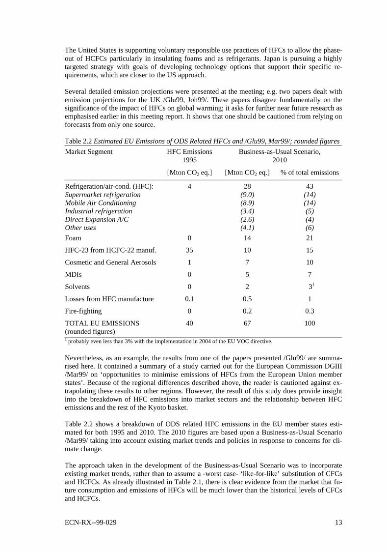
Table 2.2 Estimated EU Emissions of ODS Related HFCs and /Glu99, Mar99/; rounded figures
HFC Emissions1995
Business-as-Usual Scenario,2010
Market Segment
[Mton CO2 eq.] [Mton CO2 eq.] % of total emissions
Refrigeration/air-cond. (HFC):Supermarket refrigerationMobile Air ConditioningIndustrial refrigerationDirect Expansion A/COther uses
4 28(9.0)(8.9)(3.4)(2.6)(4.1)
43(14)(14)(5)(4)(6)
Foam 0 14 21
HFC-23 from HCFC-22 manuf. 35 10 15
Cosmetic and General Aerosols 1 7 10
MDIs 0 5 7
Solvents 0 2 31
Losses from HFC manufacture 0.1 0.5 1
Fire-fighting 0 0.2 0.3
TOTAL EU EMISSIONS(rounded figures)
40 67 100
1 probably even less than 3% with the implementation in 2004 of the EU VOC directive.
Nevertheless, as an example, the results from one of the papers presented /Glu99/ are summa-rised here. It contained a summary of a study carried out for the European Commission DGIII/Mar99/ on ‘opportunities to minimise emissions of HFCs from the European Union memberstates’. Because of the regional differences described above, the reader is cautioned against ex-trapolating these results to other regions. However, the result of this study does provide insightinto the breakdown of HFC emissions into market sectors and the relationship between HFCemissions and the rest of the Kyoto basket.
Table 2.2 shows a breakdown of ODS related HFC emissions in the EU member states esti-mated for both 1995 and 2010. The 2010 figures are based upon a Business-as-Usual Scenario/Mar99/ taking into account existing market trends and policies in response to concerns for cli-mate change.
The approach taken in the development of the Business-as-Usual Scenario was to incorporateexisting market trends, rather than to assume a -worst case- ‘like-for-like’ substitution of CFCsand HCFCs. As already illustrated in Table 2.1, there is clear evidence from the market that fu-ture consumption and emissions of HFCs will be much lower than the historical levels of CFCsand HCFCs.
14 ECN-RX--99-029
The study cited /Mar99/ mentions here that ‘it is important to recognise that an accurate emis-sion forecast for the first Kyoto Commitment Period (i.e., 2008-2012) is virtually impossible tomake because there are numerous uncertainties regarding the development of HFC end usermarkets’.
The table shows significant growth of emissions in end user markets partially offset by the re-duction in HFC-23 emissions, which are emitted as a by-product of HCFC-22 production. The2010 projections show that 80% of emissions relate to refrigeration and air-conditioning, foamblowing, general aerosols and MDIs and that fugitive HFC-23 emissions from HCFC-22 manu-facture are still expected to be significant.
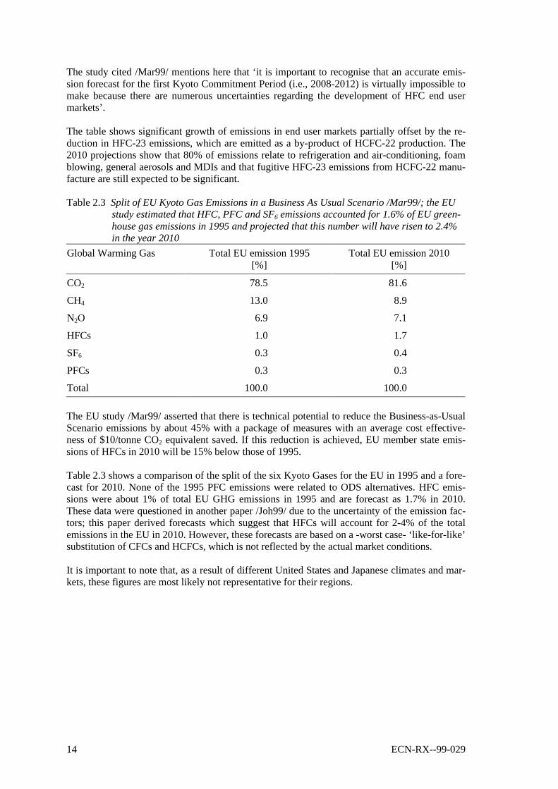
Table 2.3 Split of EU Kyoto Gas Emissions in a Business As Usual Scenario /Mar99/; the EUstudy estimated that HFC, PFC and SF6 emissions accounted for 1.6% of EU green-house gas emissions in 1995 and projected that this number will have risen to 2.4%in the year 2010
Global Warming Gas Total EU emission 1995[%]
Total EU emission 2010[%]
CO2 78.5 81.6
CH4 13.0 8.9
N2O 6.9 7.1
HFCs 1.0 1.7
SF6 0.3 0.4
PFCs 0.3 0.3
Total 100.0 100.0
The EU study /Mar99/ asserted that there is technical potential to reduce the Business-as-UsualScenario emissions by about 45% with a package of measures with an average cost effective-ness of $10/tonne CO2 equivalent saved. If this reduction is achieved, EU member state emis-sions of HFCs in 2010 will be 15% below those of 1995.
Table 2.3 shows a comparison of the split of the six Kyoto Gases for the EU in 1995 and a fore-cast for 2010. None of the 1995 PFC emissions were related to ODS alternatives. HFC emis-sions were about 1% of total EU GHG emissions in 1995 and are forecast as 1.7% in 2010.These data were questioned in another paper /Joh99/ due to the uncertainty of the emission fac-tors; this paper derived forecasts which suggest that HFCs will account for 2-4% of the totalemissions in the EU in 2010. However, these forecasts are based on a -worst case- ‘like-for-like’substitution of CFCs and HCFCs, which is not reflected by the actual market conditions.
It is important to note that, as a result of different United States and Japanese climates and mar-kets, these figures are most likely not representative for their regions.
ECN-RX--99-029 15
3. WORKING GROUP FINDINGS
3.1 Refrigeration and Air Conditioning
3.1.1 Stationary SourcesA working group of more than 30 experts intensively discussed the various aspects of limita-tions to emissions of HFCs in refrigeration. Many papers were presented to provide context forthis work. The group was co-chaired by an industry consultant and an academic researcher(TEAP HFC Task Force).
Working Group HighlightsRefrigeration and air-conditioning covers a wide range of application types, sizes, and tem-perature levels with regional variation in the applications of technology. It was suggested thatthis market diversity requires a range of flexible responses rather than uniform prescriptive so-lutions.
Prior to 1986 the main refrigerants in use were CFCs, HCFCs and ammonia. Other refrigerantssuch as brominated chemicals and hydrocarbons were used in niche markets. As a response tothe Montreal Protocol, HFC, ammonia and HC refrigerants have been promoted as the primaryalternatives to ODSs. A very small quantity of PFCs is being used in certain alternative refriger-ant blends.
From a life-cycle perspective, refrigeration systems have two distinct global warming impacts.A ‘direct impact’ occurs if the refrigerant used has a positive GWP and is emitted to the atmos-phere. All refrigeration systems also have an ‘indirect impact’ linked to the CO2 released in theproduction of energy to operate the refrigeration units5. It is estimated that for all fluorocarbonrefrigeration systems the direct impact is about 15 to 20% of the total. For the more emissiveHFC systems (e.g. supermarket refrigeration) the direct impact a decade ago was 50-60%, buthas been much reduced with new equipment and service practices to less than 20% /TOC91,TOC98/. The direct impact for stationary A/C systems (centrifugal chillers) can be less than 3%in the case of high pressure (HFC-134a) chillers and less than 0.2% in the case of low pressure(HCFC-123) chillers. For hermetically sealed systems (e.g. domestic refrigerators) the directimpact averages only about 1-3% of the total, except where refrigerators suffer large or frequentleakage rates. This calculation depends on the mix of fuels used to generate the electricity usedfor production and operation of the equipment.
Direct emission impacts of below 5% have been achieved by the developed countries (e.g. do-mestic refrigeration and stationary A/C), at the expense of considerable effort and discipline.Matching this to the developing countries in general would be a challenge and underscores theircall for capacity building (see section 3.7). Here, manufacturing methods and service practicesneed to be significantly improved compared to the approach followed with CFCs, if one wouldtry to keep the direct effect of the HFC emissions below 15 to 20% of the total (even for do-mestic refrigerators the direct effect may be larger than a few percent). This is of crucial impor-tance if HFCs will be increasingly applied in future.
5 These two impacts have been added to give the so called Total Equivalent Warming Impact (TEWI) (which adds
CO2 from energy production to CO2 equivalent from refrigerants emitted). In general the indirect impact is largerthan the direct impact over the lifetime of the equipment.
16 ECN-RX--99-029
The working group discussed issues including (1) regulatory regimes and their effectiveness (2)emission scenarios (3) energy standards, and (4) the validity of the TEWI concept (see above)versus life cycle cost analysis and life cycle performance analysis.
Major FindingsThe working group agreed upon five possible strategies, which can be followed to reduce HFCemissions (the best strategy will depend on individual circumstances of the installation):
q Use of non-HFC refrigerants These include ammonia, hydrocarbons and CO2 and arenormally associated with technically developed andcommercially available refrigeration systems. It may in-volve adequate addressing of safety issues.
q Use of alternative technology These include absorption, desiccant cooling and air cycletechnologies which are fully developed. There are otheroptions, however, so far, not commercialised. Care mustbe taken to fully assess the energy efficiency implicationsof these alternatives – in many situations the globalwarming impact would be higher than conventional tech-nologies due to higher energy consumption.
q Containment by design andquality of components This involves incorporating measures into the design and
manufacture of the equipment in order to reduce leakagepotential.
q Containment during operation This revolves around the installation, maintenance andservicing procedures that are designed to reduce leakagepotential.
q Containment on disposal This means that HFCs are properly recovered from anyequipment upon disposal and recycled or destroyed.
The participants discussed the crucial importance of energy efficiency in relation to indirectglobal warming impact. Using an alternative refrigerant or an alternative technology can havean important influence on energy usage. In some cases (e.g. evaporative cooling) this is a bene-ficial effect. In other cases (e.g. use of direct fired absorption equipment or low temperature in-direct systems) the effect is an energy penalty which can lead to CO2 emissions that far out-weigh the benefits from reduced HFC emissions. These effects are strongly application and de-sign dependent and must be carefully taken into account when considering emission reductionstrategies, according to many experts in the Joint Expert Meeting.
Where it concerned the CO2 emissions from energy production, a minority of the participantsinterpreted the mandate of the relevant decision more narrowly than others; they argued that in-direct emissions should be disregarded and that the issue of energy efficiency was beyond thescope of the Joint Expert Meeting.
3.1.2 Mobile Sources
Working Group HighlightsThe report of the working group on Mobile Air Conditioning, originally a sub-group of the Re-frigeration and A/C Working Group, was included in the meeting report as a separate item; thisis due to the importance of mobile air conditioning to potential HFC emission reductions. Theworking group consisted of eight experts from automotive and component manufacturers, andthe chemical industry, as well as university and independent consultancies (representing allmajor car manufacturing regions in the world). The report was based on one presentation in ple-nary, several past publications and the working papers and the experience of the participants.

ECN-RX--99-029 17
All of the cars manufactured in developed countries and most currently manufactured in the de-veloping countries have energy efficient (according to manufacturer’s standards) HFC-134a airconditioning systems. These systems have current typical emissions of about 170 g HFC-134aper year per car. This would imply a total annual leakage of 60,000 tonnes of HFC-134a, as-suming a global fleet of 350 million cars, if they were all equipped with HFC-134a air-conditioning, which does not reflect the current situation. During the 1980’s, the net emissionrate associated with auto air conditioners was about 450 g CFC-12 per year per car.
Major FindingsThree major options were identified to reduce emissions of HFCs: (1) containment and im-proved servicing practices, (2) carbon dioxide systems, and (3) the use of hydrocarbons com-bined with secondary loops. The latter two options would result in zero HFC emissions. There isthe potential that more than one technology will be present in the market, but the desire for sim-plicity for servicing drives towards a single technology.
Substantial reductions in HFC emissions from mobile air conditioners has already beenachieved by producing tighter systems, and redesigning them so as to reduce the amount of re-frigerant needed compared to the CFC systems. Additional emission reductions can be gainedby improving service practices, requiring certified service personnel and, especially, proper on-site recovery, recycling and recharging. Although there are no technical barriers to achieve theseleak reductions, incentives by governments are necessary to initiate the required investmentsand training. Such combined measures could lead to an average reduction of emissions to 80 gper year, with some regional emissions down to 50 g per year by 2008 in developed countries(approximately 85% of the global fleet). For certain regions, this may imply a reduction ofabout 60% per car compared to the order of magnitude of the current emissions. In 2008, totalemissions in the developed countries will be between 27,000 tonnes and 36,000 tonnes of HFC-134a assuming a fleet of 450 million cars with air conditioning systems. In developing coun-tries, containment measures should focus on similar steps. These measures may be applicable tocertain markets. However, in most developing countries and in countries with economies intransitions the optimum recovery, recycling and recharging scenarios will be difficult toachieve.
Carbon dioxide and secondary loop hydrocarbon systems are potential future options for auto-motive air conditioning systems. For both systems, significant issues remain requiring furtherresearch and development work. Experts in the working group reported that current designsutilising alternative refrigerants show an efficiency decrease and cost increase in comparison toHFC designs. However, this requires further verification; not all participants in the workinggroup agreed on the estimates given, some were confident that optimised designs could be en-ergy efficient. The challenge is to bring alternative refrigerant systems to an efficiency, cost,safety and reliability level comparable with present and future HFC systems. Further discus-sions on energy efficiency should wait until adequate standards have been developed by whichmobile air conditioning energy efficiency is measured across different technologies.
3.2 Foams
Working Group HighlightsA group of between 10 and 15 experts, covering technical, economic and regulatory aspects ofinsulating foams, were able to review the potential for lowering the emissions of HFCs fromthese applications. In doing so, the group needed to assess the likely future usage, since mostapplications that will use HFCs are still currently based on HCFCs. Six papers were presentedto provide context for this work. This formed the basis for the numbers given below under‘major findings’. The group was co-chaired by an industry consultant (TEAP) and an academicresearcher (IPCC).

18 ECN-RX--99-029
There is little current use of HFCs as blowing agent in the foam sector; without regulationsmandating responsible use, a considerable growth may take place in future. It should be notedthat future use will be limited to only some of those applications where CFCs and HCFCs arecurrently utilised with HFCs replacing less than 50% of the HCFCs and approximately 25% ofthe CFCs on a weight basis. The primary application of HFCs will be in closed cell thermal in-sulation foams.
0
50000
100000
150000
200000
250000
1960 1965 1970 1975 1980 1985 1990 1995 2000 2005 2010
Year
Blowingagent usage[metric ton]
Total HFCs
Total HCFCs
Total CFCs
Fig. 3.1 CFC/HCFC/HFC blowing agents in use or expected to be in use globally in rigidfoams /Ash99/
Insulation material use is driven by the desire to save energy and, as a consequence, reduce CO2
emissions. The uses extend to the buildings, building services, industrial and food preservationsectors.
Major FindingsIt is estimated that the HFC use in the foam sector will be approximately 75,000 tonnes in 2005,growing to 115,000 tonnes in 2010. Thereafter, the foam market growth is anticipated to run at4-6% per annum, although there may be some gradual reduction in HFC use within the extrudedpolystyrene sector, which will offset this growth to some extent. This could leave HFC use infoams at a level of between 160,000 and 205,000 tonnes in 2020 /Ash99/. The situation is sum-marised for the period to 2010 in Figure 3.1.
ECN-RX--99-029 19
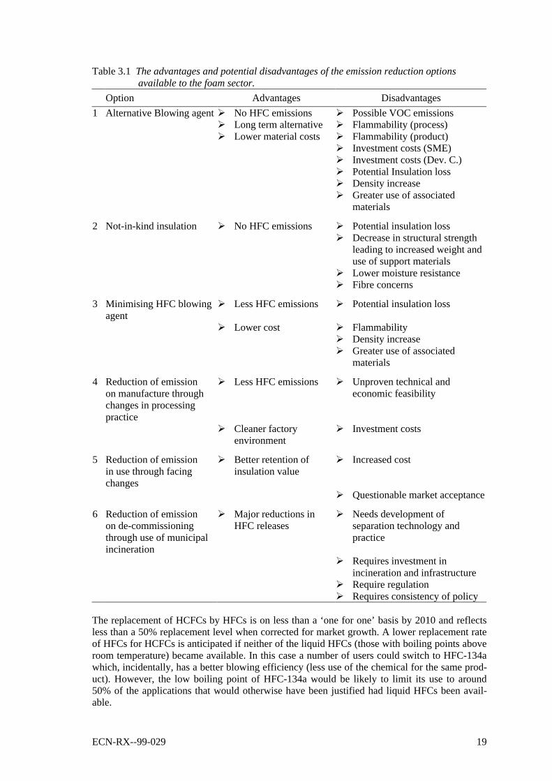
Table 3.1 The advantages and potential disadvantages of the emission reduction optionsavailable to the foam sector.
Option Advantages Disadvantages
1 Alternative Blowing agent Ø No HFC emissions Ø Possible VOC emissionsØ Long term alternative Ø Flammability (process)Ø Lower material costs Ø Flammability (product)
Ø Investment costs (SME)Ø Investment costs (Dev. C.)Ø Potential Insulation lossØ Density increaseØ Greater use of associated
materials
2 Not-in-kind insulation Ø No HFC emissions Ø Potential insulation lossØ Decrease in structural strength
leading to increased weight anduse of support materials
Ø Lower moisture resistanceØ Fibre concerns
3 Minimising HFC blowingagent
Ø Less HFC emissions Ø Potential insulation loss
Ø Lower cost Ø FlammabilityØ Density increaseØ Greater use of associated
materials
4 Reduction of emissionon manufacture throughchanges in processingpractice
Ø Less HFC emissions Ø Unproven technical andeconomic feasibility
Ø Cleaner factoryenvironment
Ø Investment costs
5 Reduction of emissionin use through facingchanges
Ø Better retention ofinsulation value
Ø Increased cost
Ø Questionable market acceptance
6 Reduction of emissionon de-commissioningthrough use of municipalincineration
Ø Major reductions inHFC releases
Ø Needs development ofseparation technology andpractice
Ø Requires investment inincineration and infrastructure
Ø Require regulationØ Requires consistency of policy
The replacement of HCFCs by HFCs is on less than a ‘one for one’ basis by 2010 and reflectsless than a 50% replacement level when corrected for market growth. A lower replacement rateof HFCs for HCFCs is anticipated if neither of the liquid HFCs (those with boiling points aboveroom temperature) became available. In this case a number of users could switch to HFC-134awhich, incidentally, has a better blowing efficiency (less use of the chemical for the same prod-uct). However, the low boiling point of HFC-134a would be likely to limit its use to around50% of the applications that would otherwise have been justified had liquid HFCs been avail-able.
20 ECN-RX--99-029
The justifications for use of HFCs are limited to thermal efficiency, product performance andprocess safety. It is recognised that one of the key measures to reduce HFC emissions is not touse them in unjustified applications and this is reflected by the inclusion of options 1 and 2 inTable 3.1. An additional four abatement options are also included and their advantages and dis-advantages listed.
Up to approximately 50% of potential emissions subsequently arising from consumption in2010 could be abated by the introduction of options 4, 5 and 6. However, the majority of thesesavings will depend on incineration procedures (see Annex B) which, whilst technically proven,may not be logistically or economically viable. Accordingly, a target of 25% destruction may bemore realistic unless evidence emerges to the contrary.
3.3 Aerosol Products
3.3.1 Non-Medical Uses
Working Group HighlightsThe UNEP Aerosols Technical Options Committee has estimated that use of HFCs (HFC-134aand HFC-152a) in 1998 does not exceed 15,000 metric tonnes globally. Data voluntarily re-ported by companies based in Europe, Japan and North America for HFC-134a sales into ‘short-term’ emission- applications (which include sterilants, non-medical aerosols, one componentpolyurethane foam and open-cell foam) were 9,342 metric tonnes in 1996 /AFE99/ (sales intoall short term uses, with the exception of medical aerosols was 6,293 tonnes in 1997 /AFE99/).With the assumptions that CFC use in non-medical aerosols have been almost entirely replacedby alternatives and that non-critical uses are likely to be constrained in the future, it is unlikelythat use/emission in 2010 will exceed 20,000 metric tonnes.
Major FindingsThe working group concluded that one option is currently available to limit HFC emissions innon-medical aerosols:• the development of criteria, either at a national or international level which determine the
criticality of the use and the availability of viable alternatives, based on real safety concerns,and adoption of these ‘responsible use’ criteria by corporations and industry to ensure thatthe use of HFCs is limited to those meeting pre-determined criteria.
3.3.2 Medical Uses - MDIs
Working Group HighlightsCFC-containing metered dose inhalers (MDIs) are reliable and effective therapy for asthma andChronic Obstructive Pulmonary Disease (COPD), such as chronic bronchitis and emphysema.CFC propellants are now being replaced with HFC-134a and HFC-227ea. Both have been ap-proved by health authorities as acceptable and safe propellants for use in MDIs. The transitionfrom CFC to HFC MDIs is likely to continue into the first decade of the 21st century. Alterna-tives to MDIs in some cases are dry powder inhalers (DPIs) and nebulisers, which do not use apropellant.
Major FindingsCompounds identified as potential substitutes for CFCs must meet particularly strict require-ments for use in MDIs. After extensive investigation, only two compounds emerged as accept-able substitutes: HFC-134a and HFC-227ea. At present, there are no other known alternativepropellants for use in MDIs. CFC-free MDIs will use approximately 30% less propellant, on av-erage, than CFC based MDIs.
ECN-RX--99-029 21
MDIs constitute approximately 75% of inhalation therapy in the world’s fifteen largest popula-tions of patients. To date, HFCs have started to play a significant role in the shift away fromCFC propelled MDIs. A concern was expressed that the transition away from CFC use in MDIsmay be slowed unless a long term solution such as HFCs is clear to patients and their physi-cians. However, the most serious barrier to the transition to non-CFC MDIs seems to be the rateat which new products are entering the market. DPIs constitute approximately 15% of the mar-ket, and their market share is growing (the percentage is much higher in countries such as Swe-den that have mandated DPI use (80% share)). At current growth rates, DPIs are not expected to-fully- replace MDIs by 2020. Assuming that current trends continue, worldwide emissions ofHFCs from MDIs in the year 2010 are projected to reach a level between 7,500 and 9,000 met-ric tonnes.
3.4 Industrial and PFC and SF6 Emissions
Working Group HighlightsThe working group consisted of 18 experts from industry (representing chemical manufacture,electric equipment insulation, semiconductor manufacture and miscellaneous industrial uses)and from consultancies. Eight technical papers were presented in this working group.
Unlike the ODS-replacement industries, this was generally the first time experts had gathered toconsider global emissions and emission reduction opportunities from aluminium, electric powerdistribution, HCFC-22 production, magnesium, chemical manufacturing and distribution, andmiscellaneous industrial uses. Consequently, significant gaps in global and regional data onuses, emissions, emission reductions and costs were identified.
Two PFCs - CF4 and C2F6 - are inadvertently emitted as emission by-products during primaryaluminium smelting. SF6 has been used for the past 30 years in electrical power distributionequipment such as high and very high voltage equipment, i.e. circuit breakers and transformers.SF6 is a highly effective dielectric insulator that has no readily available substitutes for highvoltage applications in densely populated areas. Magnesium processing (primary smelters, sec-ondary smelters, die casting) amounts to about 10% of total global use of SF6. High GWPfluorinated compounds including PFCs, HFC-23, SF6 and NF3 are currently used in the manu-facture of semiconductors. These chemicals were considered essential to current semiconductormanufacturing technology by several participants of the working group.
During the production of HCFC-22 the chemical HFC-23 is produced and emitted. It is believedthat 6 out of 11 plants in Europe will have some level of HFC abatement by around 2000.HCFC-22 producers in the USA have voluntarily committed to reduce HFC-23 emissions by 5million metric tonnes carbon equivalent from 1990 levels. Reduction activities include processoptimisation and abatement.
Major FindingsThe Petten PFC/SF6 expert work group focused on PFC emissions from aluminium manufac-ture, HFC-23 from HCFC-22 production, SF6 from electric power systems, and PFCs fromsemiconductor manufacture.
Although it is not currently technically feasible to eliminate all emissions from these industries,ways and means of reducing emissions have been identified. Very little global emissions dataand cost information was available through the workgroup, except for PFC emissions from thealuminium industry /Har99/. PFCs from aluminium and HFC-23 from HCFC-22 are inadvertentproduction by-products. Process optimisation for both of these industries are technically feasi-ble, currently available and cost-effective. Other methods exist for further emission reductionsbut may not be cost-effective for all production sites.
22 ECN-RX--99-029
Most companies in developed countries with aluminium and HCFC-22 production are engagingin emission reduction activities, and other companies can be encouraged to join these efforts.No information was available on operations in developing countries.
SF6 is used in high and very high voltage circuit breakers and electric transformers as a dielec-tric to quench electric arcing. SF6 emissions in this sector result from distribution, originalequipment manufacture, and operation and maintenance of equipment. Japan has adopted anaggressive national action plan to significantly reduce emissions in this application by 2010.Other countries (e.g. Germany and the United States) and companies have also initiated actionto reduce emissions from this sector.
PFCs, HFC-23, NF3 and SF6 are used by the semiconductor industry for etch and plasma clean-ing of chemical vapour deposition tools. In April 1999, the World Semiconductor Councilwhich represents manufacturers from Europe, Japan, Korea, Taiwan and the United Statesadopted a voluntary global emission reduction target of 10% absolute reduction from 1995emissions by 2010. This target encompasses over 90% of total semiconductor manufacture, andwill result in significant emission reduction given high industry growth rates and anticipated in-creased intensity of PFC use in the manufacturing of more sophisticated products.
3.5 Solvents
Working Group HighlightsPFCs such as C5F12, C6F14, C7F16 and C8F18 were introduced as substitutes for CFC-113 in thelate 1980’s and early 1990’s. The applications included carrier fluid for fluoro-lubricants in thecomputer industry, particulate removal in precision cleaning, electronic applications such ascooling and as dielectric fluid and rinsing agent in a co-solvent process for cleaning printed cir-cuit boards and precision cleaning of mechanical parts.
An HFC (C5F10H2, HFC-4310 mee) was introduced in late 1995 to replace CFC-113 and PFCsin some applications. Additional new compounds have been proposed in recent years but not yetcommercialised. Some of the additional applications include uses in the aerospace and aerosolindustries.
The PFC market is estimated to be around 2500 tonnes /Har99/. Current HFC uses are verysmall and are estimated to be around 500- 1000 tonnes. This represents less than 1% of theCFC-113 market in 1989. The vast majority of the market switched to not-in-kind technologiessuch as aqueous, no-clean technologies and hydrocarbons.
HFC and PFC solvents are primarily used in developed countries for specialty applicationswhere not-in-kind alternatives are not technically feasible for reasons of safety, performance orcompatibility demands.
Major FindingsThere are several emission reduction efforts currently in use, such as recovery and recycle,abatement technology, the airless degreaser, and upgrading of old degreasers (additional free-board, secondary cooling coil, etc). An upgrading of the degreaser can reduce emissions byabout 80% (e.g. the upcoming implementation of the EU directive on solvents VOC emissionsshould lead to the containment of HFC solvents and to an emission reduction of about 65%).
It is expected that PFCs will be replaced in most applications by the lower GWP alternatives(HFCs and HFEs, hydrofluoroethers) over the next 10 years, however, no suitable low GWPalternatives are available in some applications. In some cases HFEs may also replace HFCs.Overall growth of this market is not anticipated to be too large due to high cost of these alterna-tives, and already low usage rates of PFC and HFC solvents.
ECN-RX--99-029 23
3.6 Fire Extinguishants
Working Group HighlightsThe working group consisted of representatives of CEIT and developed countries, includingrepresentatives of governments, main users (the military sector), system suppliers, HFC manu-facturers and an environmental NGO, and the group was chaired by present and former co-chairs of the UNEP Halons Technical Options Committee.
HFCs are important halon substitutes primarily in occupied areas where space and weight areconstrained, or speed of fire suppression is important. HFC growth is limited by high systemcost compared to other choices. PFCs are not technically necessary except in very rare circum-stances. HFC emissions from fire fighting are forecast to be around 0.3% of all HFC emissionsby 2010. HFC emissions from all sources are approximately 2% of GHG emissions, and firefighting emissions account for only 0.006% of all GHG emissions on a GWP weighted basis.
Furthermore, there are a large number of halon alternatives applied in the substitution process asgiven in Table 2.1.
Major FindingsRestrictions on HFC use may increase halon use; the likelihood that an essential use exemptionunder the Montreal Protocol would be necessary to satisfy critical halon needs would then alsoincrease. If restrictions were to be put in place for the use of halons, this would also guaranteeavailability of recovered halon for critical uses where no viable alternative has been found. Thisparticularly applies to critical halon-1301 needs.
Annual loss rates from halon systems have declined from 25% of the installed base before theMontreal Protocol to around 4-6% today due to changes in industry practice in many developedcountries to conserve halon. These include ending system discharge testing and training, use ofleakage detection and improved maintenance. These practices were institutionalised in a numberof countries and now apply to HFCs. Options available for implementation before 2010 thatcould reduce emissions of the new fluorocarbon systems by up to an additional 50% include:(A) Incentives to industry to invest in best installation and maintenance practice, (B) Field re-covery and recycling, and (C) End-of-useful-life reclamation and transformation.
3.7 Developing Country Aspects
Working Group HighlightsThe working group was co-chaired by a representative from the Multilateral Fund Secretariatand a representative from UNIDO. Participants represented developing country ozone officers,UNDP, GEF, TEAP members, chemical suppliers and some (environmental) research institutes.
Two papers were presented, one by a chemical supplier, and one by the ozone network managerfor the Latin American and Caribbean region. The latter one presented the information gatheredduring a Latin American Ozone Officers Network meeting, a Regional Workshop on Refrigera-tion and Air Conditioning and additional comments provided by some Ozone Officers. Itformed the basis for the discussions since it covered most of basic points to be addressed by theworking group. The group first discussed general concerns relating to the specific situation ofdeveloping countries and then focused on the analysis of options to reduce HFCs emissions.
24 ECN-RX--99-029
Developing countries share the global concerns for stratospheric ozone and climate protection.The choice of technology is a balance of technology maturity and availability, cost effective-ness, energy and other performance, and safety and safety costs. In addition to the guidancegiven by MLF decisions and implementing agencies in the evaluation of options, the choice isalso influenced by: local circumstances, preferences of enterprises, their joint venture partnersand customers, availability of training and other market circumstances and regulatory compli-ance.
Concerns were expressed related to the fact that the uncertainty on possible controls on HFCs indeveloped countries might adversely affect compliance with Montreal Protocol obligations par-ticularly for the refrigeration, air conditioning and foam sectors. The importance of guarantee-ing supplies of chemicals and components for maintenance and services was emphasised forthose developing countries that have selected HFC technology.
The following can be stated where it concerns sector choices of substitutes in projects financedby the Multilateral Fund (MLF) (as % of sector ODP-tonnes total). No projects in the solventssector used HFCs; in the aerosol sector only one project used HFCs, while in the halons sector 6projects were identified replacing halon-1301 with HFCs. 21% of the total ODP-tonnes used inthe refrigeration sector (including insulation foam) is being replaced by HFCs, 24% by HCFCs,53% by hydrocarbons and 2% by other technologies. 93% of the refrigerant chemical replace-ment was with HFCs, and 7% with hydrocarbons. In the foam sector, the contribution of non-ODP and low-GWP alternatives as replacements for ODSs is about 75%, 24.6% of uses was re-placed by HCFCs and only 0.2% by HFCs.
Enterprises, governments and implementing agencies need complete information on the meritsof available options. Developing countries also need to have guidance on the implications of theselection of different alternatives, perceived risk related to technical and economic performance(including safety) and market structure. Deficiencies in infrastructure and lack of incentives arefactors that inhibit best servicing practice.
Major findingsIn analysing options to reduce HFC emissions, constraints as well as several opportunities havebeen identified:
Constraints:• The need to improve information on technology options that can help enterprises to have a
fully informed choice; a clearer scenario on the implications of the selection of different al-ternatives, especially for small and medium enterprises (SMEs); the perceived risk relatedto technical and economic performance (including safety) and market structure; the defi-ciencies in infrastructure and lack of incentives as factors that inhibit best servicing prac-tice; institutional weakness as a prejudice to regulatory enforcement; and lack of access tocommercial financing sources that would allow enterprises to make needed investments intechnology (that otherwise would pay by itself).
Opportunities:• The selection of low-GWP alternatives in uses where non-GWP alternatives are not avail-
able or cannot be used; product redesign to acquire leak tightness and energy efficiency,better practices in production, servicing and recovery and recycling, improved performancestandards, and supporting policy and regulatory initiatives; HFC recycling can build on ex-pertise developed through Multilateral Fund (MLF) funded ODS recovery and recyclingprojects and associated training activities, and developed countries experience with HFC re-covery, recycling and reclamation can aid the process. A blend of all the above options isneeded depending on specific circumstances and applications.
ECN-RX--99-029 25
The MLF finances the agreed incremental costs for ODS phaseout in the developing countries,and the Global Environment facility (GEF) assists in phasing out ODSs in countries witheconomies in transition. Under the MLF, enterprises are only eligible once for financial assis-tance. This makes it crucial for an enterprise to choose a technology that is cost effective, envi-ronmentally acceptable, and globally sustainable. The MLF is only empowered to invest inozone layer protection while the GEF is empowered to invest in energy efficiency for climateprotection (up to US$ 10 per ton of carbon equivalent abatement over the life-cycle of the rele-vant investments) and also in low-GWP technologies. There was a strong sense expressed in theplenary that the MLF and the GEF should co-operate in funding the development of energy effi-cient refrigeration, air conditioning and other equipment, and that the MLF should also considerenergy efficiency as well as ODP in the projects that it funds alone. Such an integrated approachwill not only address goals of both Protocols, but will enhance the sustainability of the devel-opment process by reducing the demand for additional electric power production.
Potential Cost-Effective Climate Protection During Conversion from ODSsIncremental investment could complement ozone protection technology sponsored by the MLFby providing improved energy efficiency. Incremental investment in energy efficiency duringconversion from ODSs would be highly cost effective and institutionally efficient. Higher en-ergy efficiency helps protect the climate and reduces operating costs. Unfortunately, such co-ordinated investment had not occurred until recently.
Participants in the Joint Expert Meeting strongly supported the expansion of dual-purpose ozoneand climate projects. Representatives of the MLF and GEF agreed to co-ordinate considerationof such projects. They pointed out that applicants are responsible for proposing the joint fund-ing. CEIT and Article 5(1) countries at the Joint Expert Meeting welcomed additional fundingfor climate protection enhancements to GEF and Multilateral Fund ozone protection invest-ments.
Investment Choices Should be Fully Informed and RespectedThe Montreal Protocol has encouraged CEIT and Article 5(1) countries to phase out CFCs byearly adoption of new alternatives including HFCs and other options.
Some participants expressed their concerns that some developed countries may try to imposetheir own choice of technology on developing countries. Such efforts could undermine trust andmutual respect under the Protocol and would be counterproductive if developing countries be-gan to doubt that advice given under the Montreal Protocol. This could undermine credibility offuture global environmental treaties. It is also essential that technologies chosen to address cli-mate change and ozone protection meet the sustainable development goals of developing coun-tries. In addition, it appears that developing countries are choosing CFC replacements to someextent based upon historic or new commercial links to developed countries in addition to costconsiderations.
26 ECN-RX--99-029
4. CONCLUDING REMARKS
The IPCC/TEAP Joint Expert Meeting was the first opportunity for representatives of govern-ments, international agencies, environmental organisations and the private sector to meet andexplore co-ordinated actions that might be taken to address the atmospheric problems of strato-spheric ozone depletion and climate change. It also provided the first opportunity for expertsworking on the climate problem through IPCC and those working on ozone depletion throughTEAP to discuss their common and separate issues in the same forum. The meeting was held inPetten, the Netherlands, 26-28 May 1999, and was attended by over 100 participants from 24nations.
Within the framework of the Montreal Protocol it has been recognised that substitutes for ozonedepleting substances (ODSs) should be compatible with the goals of climate protection. Techni-cal assessments have also utilised measures such as the Total Equivalent Warming Impact(TEWI) factor to study the implications for global warming of energy associated CO2 emissions.However, the actual implementation of the Montreal Protocol cannot mandate climate changeconsiderations since it only controls listed substances directly involved in ozone depletion. TheKyoto Protocol has created a more immediate need to further examine the relationship betweenthe climate and ozone treaty regimes. It includes the hydrofluorocarbons (HFCs) among thegases that are to be controlled for climate protection, and these are the principal substances cho-sen as substitutes for ODSs under the Montreal Protocol.
The widely different replacement strategies for ODSs among countries demonstrate the need formore explicit international co-ordination of actions taken to address ozone depletion and climateprotection simultaneously. The future choices of ODS substitutes are important for maintainingenvironmental quality and a sound economy, encouraging technological innovation, and for as-suring developing countries an improved quality of life. These concerns formed the background,as well as a very important part for all discussions at the Joint Expert Meeting. Furthermore, theMeeting also provided an opportunity for specialists to examine the implications for both theglobal environment and the global economy of the Kyoto greenhouse gases which contribute toglobal warming, but which do not affect the ozone layer directly, such as CO2, SF6, and the per-fluorocarbons (PFCs).
The Joint Expert Meeting consisted of a one day plenary followed by working sessions organ-ised by end-use application. The sectors projected to consume the largest amount of HFCs, arethe refrigeration, mobile and stationary air conditioning industry, followed by insulating foammanufacturing, solvent and fire extinguishants, aerosol applications and medical devices. Use ofPFCs and SF6 is more specifically confined to narrowly defined sub-sectors such as chemicaland metals manufacturing, electronics and specialty products. At the Meeting, each workinggroup identified numerous technical options and management techniques for limiting emissionsfrom specific applications. Particularly for HFC substitutes for CFCs, the working groups de-veloped unprioritised lists of available and emerging options.
The experts concluded that while alternatives may not yet be technically and economically fea-sible for some current uses, there are technologies for other uses that can further reduce ofODSs and global warming gases in the near future. Plenary presentations also made clear thatdifferent governments were pursuing alternative strategies for replacing CFCs, especially in therefrigeration and air conditioning sectors. While several European governments such as Den-mark and Sweden are considering regulations to limit the use of HFCs and are encouraging hy-drocarbon and ammonia refrigerants, the United States is encouraging the use of HFCs togetherwith containment and recycling.
ECN-RX--99-029 27
Japan is following a focused strategy to encourage low GWP substitutes for specific applica-tions, while developing countries and countries with economies in transition are choosing vari-ous alternatives for CFCs depending upon commercial ties and their own industrial capacities.
The expert groups identified four distinct categories of options to reduce the emissions of HFCs,PFCs and SF6:
1. Alternative Substances and Technologies. When available, alternatives eliminate the speci-fied gas emissions entirely. A few participants in the Joint Expert Meeting believed thatsuch alternative substances are available and that these should be explored as the primaryoption. However, most of the participants cautioned that the reduction of direct globalwarming from the elimination of a gas might be outweighed by increased indirect globalwarming from carbon dioxide if energy efficiency is lowered.
2. Containment. Though there has been substantial technical progress in the containment andrecycling of HFCs and PFCs as refrigerants, blowing agents or fire extinguishants, theseprocedures have not been applied to all markets; further improvements are expected to befeasible. In some cases, containment is driven by national regulations, but several voluntaryindustry initiatives have also been significant. While improved containment can substan-tially reduce releases, it cannot be 100% effective in practice.
3. Improved System or Process Design. Altering the process or system design can substantiallyreduce emissions as has occurred with PFC releases in aluminium smelting and from elec-tronics manufacturing; it has substantially reduced emissions of HFCs and N2O associatedwith chemical manufacturing. Redesign of products can also permit the use of reducedchemical charge or use.
4. End of Product Life Recovery for Recycling or Destruction. Technology for recycling HFCrefrigerants is fully commercialised, but so far employed only when mandated by regulation(e.g., USA), or when voluntary industry association or corporate programs are in place (e.g.Australia, Japan and France). Recovery for destruction is generally not economical, al-though destruction facilities exist in several locations. Destruction at end-of-life appears tohave technical potential for major reductions in HFC releases from the foams sector, but itmay not be cost effective. The procedures for promoting recycling or destruction may alsodiffer.
For process related releases of HFCs and N2O in chemical manufacturing, or PFCs from alu-minium smelting, recovery of inadvertent by-products should be a first requirement. In a secondinstance, optimising the chemical and smelting production efficiency and redesigning produc-tion processes will minimise the generation of inadvertent by-products thereby substantially re-ducing these incidental releases. Most efforts to date have been voluntary, but these practicescan be disseminated to all manufacturers. The other alternative is end-of-the-pipe capture withdisposal or recycling.
At the Joint Expert Meeting, the relationship between the global warming impact of HFC emis-sions and energy efficiency gains or losses, which may result from the use of non-HFC tech-nologies, was discussed at great length. The insulation foam working-group considered energyefficiency as the most important element influencing the possible use of HFCs, while the refrig-eration and air conditioning group was divided on the importance of considering energy effi-ciency. A small number of participants believed energy efficiency to be beyond the mandate ofthe Joint Expert Meeting whereas the majority of participants were of the opinion that it must beconsidered. Considering the full, life cycle global warming contribution when making choicesof gases, technologies and processes under both the Montreal and Kyoto Protocols can help tomeet both sets of treaty goals sooner and more cost effectively. Furthermore, the Meeting alsonoted that there is a need for standardised equipment testing procedures among technologies andcountries.
28 ECN-RX--99-029
One government representative explicitly emphasised that despite the global warming reduc-tions from the elimination of CFCs, there continues to be a need to limit the emissions of HFCsand PFCs by prohibiting their use, while also doing more to increase energy efficiency ofbuildings and appliances.
There was a strong plea to assist developing countries and countries with economies in transi-tion in simultaneously improving the energy efficiency of appliances and systems while assist-ing them in shifting away from CFCs in refrigeration, air conditioning, foams and other appli-cations. While not required to eliminate CFCs until 2010, many developing countries have al-ready proceeded in the transition process away from ODSs. The Meeting requested that moresynergistic projects be financed jointly by the Multilateral Fund and the Global EnvironmentalFacility, and that a simple, dual-goal application process be devised. An overcomplicated proj-ect application system on the other hand would discourage such efforts.
Developing countries expressed concern that some developed countries may try to impose theirown choice of technology on developing countries. Such efforts could undermine trust and mu-tual respect under the Protocol and would be counterproductive if developing countries wouldbegin to question the advice given within the Montreal Protocol framework. Specifically, con-cerns were expressed that uncertainty on possible controls to address climate change may ad-versely affect compliance with Montreal Protocol obligations particularly for the refrigeration,air conditioning and foams sector. This could undermine credibility of future global environ-mental treaties. It is also essential that technologies chosen to address climate change and ozoneprotection meet the sustainable development goals of developing countries.
Data presented at the Expert Meeting clearly demonstrated that consumption of CFCs and ha-lons reached its peak in terms of their contribution to ozone depletion and global warming in theyear 1988. In the ten years since, the actions taken under the Montreal Protocol have reducedthe ODP weighted emissions of these substances and their HCFC substitutes by approximately80% (with almost 18% due to continued CFC and halon consumption in some countries). Theseactions have also decreased the direct global warming impact of all the fluorocarbons by ap-proximately two-thirds. The rate of reduction has, however, slowed between 1995 and 1997.Projecting into the future proved more difficult since it depends critically upon assumptionsabout technical feasibility of alternatives, and future demand for the services provided by thesetypes of substances.
Several sector working-groups quantified the range of technically feasible emission reductionoptions available in the near term. More detailed analysis is still needed for the many sub-sectors of refrigeration, air conditioning and heat pumps. More information is also needed to de-rive global estimates of future emissions of HFCs under different system tightness and replace-ment scenarios, and alternative assumptions concerning different emission projections, life cy-cle analysis, cost performance ratios etc. In addition, more work is needed to quantify carbondioxide emissions reductions that could be achieved at various costs through energy efficiencyimprovements in the refrigeration, air conditioning and heat pump sector and in building relatedinsulation foam. Even for the EU where data is the most detailed, scenarios differed by morethan a factor of two (1.7% to 4% of CO2 equivalents) for the level of HFC use in the EU by2010. Substantial increases in HFC use are anticipated in the refrigeration and air conditioning,insulating foam, medical and aerosol sectors, while major reductions will occur from loweredreleases of HFCs in HCFC manufacturing.
While the precise HFC growth was uncertain, it appears that the use of HFCs will be substan-tially less in amount and in terms of contribution to global warming than the CFCs and HCFCsthey replace. PFC use and release is expected to remain small because of its limited applicabil-ity, and also due to the high price of these chemicals.
ECN-RX--99-029 29
Because of the early stage of substitution and numerous uncertainties regarding the develop-ment of HFC end user markets, it was concluded that an accurate emission forecast for the firstKyoto Commitment Period (i.e., 2008-2012) is virtually impossible to make at this time.
Presentations and discussions at the Joint Expert Meeting highlighted the complexity of thelinks between ozone depletion and climate change mitigation activities, the multiplicity of solu-tions required to address these two global change issues simultaneously, and the need for solu-tions tailored to regional or national needs. The different perspectives of the experts on the pos-sible future emissions and current and future availability and feasibility of alternatives to HFCs,PFCs and SF6 in each sector demonstrates the need for substantial additional research and analy-sis to provide a valid and consistent, qualitative and quantitative picture of potential options.Despite uncertainty and differing opinions expressed at the Joint Expert Meeting, many practi-cal options for reducing emissions of these gases were identified.
30 ECN-RX--99-029
REFERENCES
/AFE99/ Production, Sales and Atmospheric Releases of Fluorocarbons through 1999, AFEAS,Washington D.C., 1999
/Ash99/ Ashford, P., ‘Considerations for the responsible use of HFCs in foams’, paper pre-sented at the Joint Expert Meeting, Petten, May 1999
/Fen99/ Fenhann, J.,’HFC, PFC and SF6 emission scenarios: recent developments in IPCCspecial report on emission scenarios’, paper presented at the Joint Expert Meeting,Petten, May 1999
/Glu99/ Gluckman, R., Yellen, D., ‘Financial implications of emission reduction options forHFCs, PFCs and SF6’, paper presented at the Joint Expert Meeting, Petten, May 1999
/Har99/ Harnisch, J., Wing, I.S., Jacoby, H.D., Prinn, R.G., ‘Primary aluminium production:climate policy, emissions and costs’, paper presented at the Joint Expert Meeting,Petten, May 1999
/Joh99/ Johnson, E., ‘Getting HFC/PFC emissions right: towards more robust estimates’, pa-per presented at the Joint Expert Meeting, Petten, May 1999
/Mai98/ Maiss, M. and Brenninkmeijer, C.A.M., ‘Atmospheric SF6, trends, sources and pros-pects’, Env. Sci. Tech., 32 (20), 1998, pp. 3077-3086
/Mar99/ ‘Opportunities to Minimise Emissions of HFCs from the EU’, EC DGIII, 1999 (Re-port prepared by March Consultants for the EC DG III)
/McC99/ McCulloch, A., ‘Halocarbon greenhouse gas emissions during the next century’, paperpresented at the Joint Expert Meeting, Petten, May 1999
/Meg99/ Mégie, G., ‘The Scientific interlinks between the Montreal and the Kyoto Protocols’,paper presented at the Joint Expert Meeting, Petten, May 1999
/Mid93/ Midgley, P.M., and Fisher, D.A., ‘The production and release to the atmosphere ofchlorodifluoromethane (HCFC-22), Atmos. Environ., 30, 1993, pp 1621-1629
/Mon98/ ‘1997 Update of the handbook for the international treaties for the protection of theozone layer’, Ozone Secretariat, United Nations Environment Programme, published1998, ISBN 92-807-1703-0
/Ora98/ Oram, D.E., Sturges, W.T., Penkett, S.A., McCulloch, A., and Fraser, P.J., ‘Growth offluoroform (HFC-23) in the background atmosphere, Geophysical Research Letters,25(1), 1998, pp. 35-38
/Sci94/ ‘Scientific assessment of Ozone Depletion: 1994’, World meteorological Organisa-tion, Global Ozone Research and Monitoring Project, Report No. 37, February 1995,ISBN 92-807-1449-X
/Sci98/ ‘Scientific assessment of Ozone Depletion: 1998’, World meteorological Organisa-tion, Global Ozone Research and Monitoring Project, Report No. 44, February 1999,ISBN 92-807-1722-7
/TEA98/ 1998 Report of the Technology and Economic Assessment Panel under the MontrealProtocol, UNEP Nairobi, Ozone Secretariat, December 1998, ISBN 92-807-1725-1,(see also: 1998 Report of the Refrigeration Technical Options Committee /TOC98/)
/TOC91/ 1991 Assessment Report of the Refrigeration, Air Conditioning and Heat PumpsTechnical Options Committee, UNEP Nairobi, Ozone Secretariat, December 1991
/TOC98/ 1998 Assessment Report of the Refrigeration, Air Conditioning and Heat PumpsTechnical Options Committee, UNEP Nairobi, Ozone Secretariat, October 1998,ISBN 92-807-1731-6
/UNE98/ Data for production and consumption of ozone depleting substances (through 1996;and updates for data through 1997), UNEP Nairobi, Ozone Secretariat, October 1998
ECN-RX--99-029 31
ANNEXES
In this part of the report supplementary material as discussed in the meeting is presented. It hasbeen done in the form of annexes, which vary in length. In some cases it was possible to bringall the material to one section in the main part of the report. In particular cases there is some re-dundancy due to the fact that the material presented should be understandable in its annex form.
ANNEX A REFRIGERATION AND AIR CONDITIONING
Stationary SourcesRefrigeration systems may have two distinct global warming impacts. A ‘direct impact’ occursif the refrigerant used is emitted to the atmosphere. All refrigeration systems also have an ‘indi-rect impact’ linked to the emissions from the energy consumed. In general the indirect impact isfar larger than the direct impact over the lifetime of the equipment. It is estimated that for allrefrigeration systems the direct impact is about 15 to 20% of the total. For the more emissiveHFC systems (e.g. supermarket refrigeration) the direct impact a decade ago was 50-60%, buthas been much reduced with new equipment and service practices to less than 20%. The directimpact for stationary A/C systems (centrifugal chillers) can be less than 3% in the case of highpressure (HFC-134a) chillers and less than 0.2% in the case of low pressure (HCFC-123) chill-ers. For hermetically sealed systems (e.g. domestic refrigerators) the direct impact is only about1-3% of the total, except where refrigerators suffer large or frequent leakage rates.
There are a number of ways in which future emissions of HFCs and PFCs can be significantlyreduced (the best strategy will depend on individual circumstances of the equipment):
a) Use of alternative refrigerants. HFC refrigerants can be replaced using other alternativessuch as ammonia or HCs, which forms a major way to reduce HFC emissions. Ammonia al-ready has a significant market in the large industrial refrigeration sector and is gaining mar-ket share for smaller industrial systems, prototype air-conditioning applications and proto-type supermarket systems. There are currently ammonia air conditioning systems in hospi-tals, shopping centres, universities, hotels, banks, airports, conference centres, office build-ings and government buildings. HCs have established a significant market in domestic re-frigeration. In Germany the whole industry has switched to HCs, and refrigerators and dis-play cases using hydrocarbon refrigerants are also manufactured in Austria, Australia,China, Denmark, India, Italy, Sweden etc. Hydrocarbons are gaining market share in arange of small commercial, supermarket, air-conditioning applications and liquid chiller ap-plications. Other refrigerants such as water are being used in niche markets. When flamma-ble or toxic alternatives such as HCs and ammonia are used in public locations they must bedesigned to mitigate the potential hazard (e.g. by using secondary refrigerant heat transfersystems); this can be achieved by following the requirements laid down in published safetystandards in many countries.
b) Use of alternative technologies. HFC refrigerants can be replaced using other cooling tech-nologies such as evaporative cooling or absorption refrigeration in the appropriate applica-tions, which avoids any HFC emissions. In several cases the energy efficiency implicationsof the non-HFC technology are unknown and need evaluation for specific circumstances.Not-in-kind technologies such as acoustic compression helium cooling or Peltier thermoe-lectric are not yet commercially demonstrated.
32 ECN-RX--99-029
c) Containment by improved design and manufacture of new equipment. Original EquipmentManufacturers (OEMs) and other primary manufacturers have taken and are taking steps toreduce refrigerant charge, reduce component leak rates and improve leak testing and qualitycontrol.
d) Containment by improved installation, operation and maintenance. Contractors and end us-ers can improve on-site practices to reduce emission rates.
e) Containment by improved recovery, recycling and disposal. Emissions at the end of life canbe reduced by better disposal practices. For large systems this involves actions from end us-ers and their contractors. For domestic and small commercial systems this will require anappropriate infrastructure which could be private contractors or municipalities. This tech-nology currently exists and is being practised for refrigerants in a variety of refrigerationand A/C applications, such as domestic refrigeration, chillers etc.
A recent report /Mar99/ (submitted to European Commission DG III) showed that 1995 EUemissions from refrigeration and air-conditioning equipment were 4.3 Mtonnes CO2 equivalent,which represented 10% of EU HFC emissions in that year. Estimates for a Business-as-UsualScenario for 2010 showed a growth in emissions to 28.2 Mtonnes CO2 equivalent. It should benoted that this Scenario took into account the fact that the climate change issue has already in-fluenced many companies to improve refrigerant containment or use alternative fluids and thatthese improvements will continue. An analysis of emission reduction technologies showed that,by 2010, a substantial emission reduction could be achieved for about $15 to 20/tonnes CO2
saved.
One presentation demonstrated a global warming advantage for large HCFC-123 based waterchillers (ODP 0.012 and GWP 120) 6. HCFC-123 may be an interesting refrigerant from thepoint of view of energy efficiency; it should, however, be borne in mind that the current Mont-real Protocol schedules require a virtual phaseout of all HCFCs by 2020 for the developedcountries, and a total phaseout by 2030.
6 One presenter requests that this issue is elaborated upon since the working group allocated a substantial amount of
time on this issue and he would like to see the following reflected: ‘The working group addressed the question ofrefrigerant selections for large chillers. The majority of new centrifugal chillers currently use HCFC-123 as a re-placement for CFCs. The next most common refrigerant in this application is HFC-134a (ODP 0 and GWP 1300);neither ammonia nor hydrocarbons are used in centrifugal chillers for safety and performance reasons. Data frompeer reviewed journal publications were presented to show that the phaseout of HCFC-123 will increase net im-pacts on global warming by 14-20% (above non-HCFC chiller applications), owing primarily to its efficiency ad-vantage, as contrasted to less than a 0.001% increase in peak bromine-chlorine loading. There was strong contro-versy in the working group on whether to consider an HCFC (an ODS) as an alternative to avoid increased use ofHFCs. There was also controversy on whether energy related impacts should be addressed at this meeting. Theworking group voted to note that HCFC-123 use warrants examination for chillers based on its negligible impact onozone depletion and strong benefit in reducing global warming.’
ECN-RX--99-029 33
ANNEX B FOAMS
As noted previously, insulation material use is driven by the desire to save energy and, as a con-sequence, reduce CO2 emissions (the uses extend to the buildings, building services, industrialand food preservation sectors. To provide a measure of the importance of energy efficiency inthe buildings sector, it should be noted that an average increase in global energy efficiency of1% in buildings would equate to an additional reduction in emissions of approximately 80Mtonnes of CO2 annually).
Not-in-kind insulation materials such as mineral fibre have a major part to play in the saving ofenergy but the additional efficiency per unit thickness arising from the use of foams in somecases enables higher energy efficiency. Insulating foams already account for at least 30% of theoverall global insulation market despite their higher cost per unit volume and this percentage isexpected to grow. The energy efficiency of a foam type can be further affected by the choice ofblowing agent, although the significance of these differences is dependent on the product typeand application. Energy efficiency considerations will promote the utilisation of HFCs mainly ininsulation applications. However, it should be noted that 25% of all insulating foam in thepolyurethane sector is currently based on hydrocarbon blowing agents.
In some cases, such as polyurethane spray foam, process safety is an issue. In other areas, suchas polyisocyanurate and phenolic foams, the behaviour of the product during fires is the keydeterminant. In the 2002-2010 timeframe it is estimated that 50% of projected HCFC use in ex-truded polystyrene will switch to HFC blowing agents. In addition, for those applications in thepolyurethane sector in developed countries which have not switched to hydrocarbons or CO2 by2004, liquid HFCs (liquid at room temperature) such as HFC-245fa and HFC-365mfc are theleading candidate alternatives, despite their projected higher cost. Similarly most polyiso-cyanurates and phenolics will also switch directly to HFCs.
The long lifetime of insulation foam applications (15-50 years) makes emission modelling acomplex issue. The work that has been carried out so far on the use of HFC-134a in extrudedpolystyrene suggests a projected emission of around 12,000 tonnes (15.6 Mtonnes CO2 equiva-lent) in 2010 from a 25,000 tonne annual usage level at that time. Given that applications usingHFC-134a can be more emissive than others, the introduction of 40-55,000 tonnes of liquidHFCs is expected to less than double the annual emissions in 2010. Accordingly emissions ofaround 25-30 Mtonnes CO2 equivalent are expected in 2010. With on-going optimisation ofHFC use and some further blowing agent substitution continuing after 2010 it is difficult toforecast whether the HFC emissions from closed cell insulation foams will much exceed the 50Mtonnes CO2 equivalent emission level during the coming decades. The reason is that no reli-able estimation methods are available to date.
A net effect of the long life-time of insulating foam applications is that emissions are spreadover extended periods, which could be many decades. The impact of reduction measures willtherefore equally be spread over significant periods and reductions may be achieved many yearsafter the consumption of the blowing agent. Notwithstanding this fact, it has been possible toassess what might happen to the consumption scheduled for 2010 (115,000 tonnes). The out-come of this assessment is that up to 57,000 tonnes (49%) of potential emissions can be abatedby the introduction of reduction measures 4, 5 and 6 alone. However, the important fact to noteis that over 50,000 tonnes (88%) of these savings will depend on the use of incineration proce-dures at end-of-life. Whilst the technology of this approach is well understood (e.g. the Euro-pean TAMARA study), the practical efficacy and economic viability are still unknown. A recentextended trial in the Netherlands has found the extraction and separation of foams from buildingwaste difficult and it is clear that further work will be required to perfect separation techniques
34 ECN-RX--99-029
and procedures. The situation may be eased somewhat in the future by the fact that insulation,particularly in the commercial and industrial sectors, is increasingly being installed in prefabri-cated elements (e.g. steel panels) which can be de-mounted and shipped for incineration. In-deed, it is only the more traditional boardstock applications which threaten real separationproblems. However, boardstock currently accounts for nearly 20,000 tonnes of the potentialsavings based on current market splits.
The value of early action in the area of incineration infra-structure cannot be over-stressed,since there is a further opportunity to destroy a significant quantity of CFCs and HCFCsamassed in existing insulation materials. Although the net benefit of such action to the globalclimate change emission reduction strategy depends on the GWP assigned to the CFCs andHCFCs, it is estimated that annual CFC-11 emissions amounting to well in excess of 100 Mton-nes CO2 equivalent could be abated. This is more than double the projected maximum annualemissions arising from the use of HFCs in rigid insulating foams.
ECN-RX--99-029 35
ANNEX C AEROSOL PRODUCTS
Non-medical UsesCFCs were used extensively as aerosol propellants. Sales by companies in the developed coun-tries exceeded 430,000 metric tonnes in 1976. As a result of consumer pressure and industry in-novation, the use of CFCs has been virtually eliminated in cosmetic and convenience aerosolproducts. By 1998, CFC aerosol consumption, excluding metered dose inhaler use, only oc-curred in developing countries and some CEITs with total use and emissions less than 10,000metric tonnes.
Hydrocarbons, and not-in-kind substitutes (roll-on deodorants, mechanical pump sprays) havebecome the preferred alternatives for CFCs in non-medical aerosols. HFCs have been adoptedin a small number of applications for technical and safety applications.
Virtually all aerosol consumer products can be manufactured without HFCs. For most products,hydrocarbon propellants are more economical and satisfy safety and environmental criteria.HFCs are much more expensive than common hydrocarbon aerosol propellants (HAPs) andDimethyl Ether (DME). They are only used, therefore, where a unique HFC property is needed,or to comply with safety and/or volatile organic compound (VOC) regulations.
Applications identified where the unique properties of HFCs are required include: Laboratory,analytical and experimental uses; products that must meet non-flammability regulations orspecify maximum VOC content; insecticide use on electrically energised equipment and on air-craft; and e.g. portable compressed gas dusters. Also critical technical applications can be men-tioned such as cleaning and freezing products used near soldering posts, precision mechanicalcleaning, deoxidising or lubricating near hot spots or electrical circuits (engines), and cleaningof electrical boards under tension (low voltage).
Medical Uses - MDIsThe asthma guidelines of the World Health Organisation/US National Heart, Lung and BloodInstitute (WHO/NHLBI-GINA) encourage the inhaled route as the preferred method of admin-istering medicine. Inhaled medication includes MDIs, dry powder inhalers (DPIs), and nebulis-ers. Overall use of inhaled medication is increasing due to increased disease prevalence. MDIsremain the dominant inhaled delivery system in most countries and for all categories of drugs.
According to the 1996 TEAP Assessment Report, an estimated 300 million people world-widesuffer from asthma and as many again (an estimated 600 million cases) from Chronic Obstruc-tive Pulmonary Disease (COPD). There is conclusive evidence that asthma prevalence is in-creasing as urbanisation of developing countries continues. Currently, approximately 450 mil-lion MDIs are manufactured annually world-wide. The use per capita of MDIs is low in devel-oping countries, reflecting availability, cost, and health professional practice rather than a re-duced need.
The pharmaceutical industry began an intensive search in the mid-1980s for alternatives to theCFC MDI. Three major initiatives resulted: testing of alternative propellants for MDIs; pro-grammes to improve other existing delivery systems, including the DPI and nebuliser; and ef-forts to develop new, innovative delivery systems. Pharmaceutical companies are also activelyengaged in research on alternative technologies for delivering medication to the lungs without apropellant.
36 ECN-RX--99-029
Preliminary projections indicate that worldwide emissions of HFCs from MDIs in the year 2010will be 7,500-9,000 metric tonnes. This amount translates to 10.8-12.9 million metric tonnesCO2 equivalent. Using a 1998 baseline, projections for the year 2010 were calculated, assuming(i) all CFC MDIs will be converted to HFC MDIs by 2010 and (ii) two annual MDI marketgrowth rate scenarios, 1.5 and 3%. HFC emissions were calculated by multiplying the projectedunit data for 2010 by the average amount of HFC contained in each MDI unit. In addition,weighted GWPs for HFCs used in MDIs were calculated by taking into account each company’suse of HFC-134a versus HFC-227ea. These projections were developed through a survey ofMDI companies and with reference to information contained in the 1998 and 1999 Technologyand Economic Assessment Panel Reports.
ECN-RX--99-029 37
ANNEX D INDUSTRIAL AND PFC AND SF6 EMISSIONS
PFCs from Aluminium SmeltingTwo PFCs -- CF4 and C2F6 -- are inadvertently emitted as emission by-products during primaryaluminium smelting. PFCs are generated by ‘anode effect’ which is an interruption of the elec-trolytic reduction process. Globally the aluminium industry is working to reduce the durationand frequency of anode effects which has the dual benefit of reducing PFC emissions and in-creases production yield.
Although it is not currently technically feasible to eliminate all PFC emissions, reductions arefeasible by improved process control (anode effect management, including alumina feed strate-gies, improved quality of anodes and alumina) through worker awareness training by retrofittingsmelters to improve operations through computer system upgrades and adding point feeders, byconversion of smelters to low-PFC emission technologies (side-work prebake to point feederprebake) and by improved gas capture and post-combustion for Soderberg plants. Secondary(recycled) aluminium production does not result in PFC emissions so increased rates of alu-minium recycling reduces overall emissions per unit of aluminium produced. Research on nextgeneration technologies for non-carbon anodes may ultimately lead to manufacturing processesthat do not generate PFCs.
SF6 From Gas Insulated Electrical EquipmentSF6 has been used for the past 30 years in electrical power distribution equipment such as highvoltage circuit breakers and transformers. SF6 is a highly effective dielectric that has no readilyavailable substitutes in the application for high voltage equipment. Its GWP (100 year time ho-rizon) of 23,900 is the highest value for all gases considered by the IPCC. The stock amountsare very large and amounted to approximately 14,000 tonnes in 1995.
Size of emissionsD1. With unconstrained application of techniques
Within the 'Electrical equipment sector' (equipment manufacturers and utilities) one coulddistinguish four phases of SF6 use and thus define the sources of emissions:(1) Production in equipment plant (handling, filling/testing by manufacturers).(2) Erection on site (e.g. assembly, commissioning, handling, filling, shipment).(3) Usage by utilities (leakage, maintenance).(4) Disposal by utilities (venting or recovery).
D1.1 Production of electrical equipmentFor GIS equipment, European manufacturers estimated the following default overallemission factor for equipment manufacturing: prior to 1995: 15% of total amount used atthe facility; 6% from 1996 onwards; Japanese manufacturers estimated this factor at 35%.For GIS equipment, the uncertainty in default overall emission factors is about 25%: inEurope 15 ±5% of total amount used at the facility prior to 1995 and 6 ±2% from 1996onwards; in Japan 35 ±10%.
38 ECN-RX--99-029
D1.2 Use of electrical equipmentD1.2.1 Site erection
Default emission factors expressed as percentage of SF6 stock additions are not wellestablished. Global analysis showed that for GIS this value may be about 15% for his-torical emissions in general, whereas recent European experience indicates that thisfactor may currently be about 6%.
D1.2.2 UsageDefault emission factors expressed as percentage of installed SF6 stock are not well es-tablished. Global analysis showed that for GIS this value may be about 5% for historicalemissions in general, whereas recent European and Japanese experience indicates thatthis factor may currently be about 3% and 1% in Europe and Japan, respectively.
D1.2.3 DisposalEmissions from disposal of discarded equipment can be estimated from (a) estimatedlifetime of the equipment to determine the erection year(s) of the vintage of existingequipment that is discarded, (b) stock of discarded equipment based on estimated initialstock addition in the year of erection and default 95% remainder at the time of disposal,and (c) estimated recovery fractions. Where recovery programmes are not in place,emissions would be equal to what is disposed from the tank.Estimated uncertainty ranges for defaults factors are:• Default erection losses: 15 ±5% for historical emissions in general 6 ±2% for current
practices (based on European experience).• Default leakage rates: 3 ±2% for stock installed <1980; 1 ±0.5% for the period 1980-
1995; 0.1 ±0.1% for years after 1995.• Default annual maintenance losses, including refill and leakage compensation: 5
±2% for years up to 1995 (based on global analysis of sales data); 2 ±1% for yearsafter 1995 (regional estimates are Japan 1% and Europe 3%).
• Default amount left: 95 ±5% of the initial stock.• Default lifetime: 30 ±5 years.
D2. With application of the major optionsThe amount in the equipment at the time of disposal will usually be between 90 and100% of the full initial stock. This amount will be emitted upon disposal, except whenpart of the gas is recovered for reuse or recycling. Recovery rates up to 95% are techni-cally feasible, so the residual remains in the tank that are emitted could be as low as 5%of the initial stock.
Major options to limit emissions- Promotion of recovery (or improvement of recovery rate) at each stage (gas production,
equipment manufacturing, usage and disposal by utilities)- Training of personnel who are related with gas handling, even of highly polluted SF6 after
electrical discharge and for the equipment at the end of its life- SF6 reuse and recycling, even of highly polluted SF6, whenever possible- Minimisation of the size of equipment for saving of SF6 gas amount enclosed- Extension of periodical maintenance interval- Application of non-SF6 gas equipment considering all of the related constraints.
ECN-RX--99-029 39
HFC-23 from HCFC-22 plantsDuring the production of HCFC-22 a certain amount of HFC-23 is produced (in the order of 1.5to 4 percent). The HFC-23 is separated as a vapour from condensed HCFC-22 and either ventedto the atmosphere as an unwanted by-product or recovered.
Three opportunities are demonstrated and commercially available to reduce emissions:(1) Process optimisation to minimise the quantity of HFC-23 produced.(2) Thermal oxidation to destroy the substance.(3) Pyrolysis using high temperatures in the absence of oxygen to fracture or transform the
HFC-23 molecule into compounds usable as chemical feedstocks.
There are a total of 11 HCFC-22 manufacturing plants in Europe. It is believed that 6 plants willhave some level of HFC abatement by around 2000. In the United States there are four plants.HCFC-22 is also produced in Japan, Korea, the Russian Federation, India and China.
SF6 in Magnesium MetallurgyMagnesium processing (primary smelters, secondary smelters, die casting) amounts to about10% of total global use of SF6.
Magnesium production is still growing because use of light alloys is increasing in the automo-tive and aeronautics sectors. There is a potential to reduce emissions per kg of magnesium pro-duced through technology improvement (handling, recovery and other slanketing operations),and by substitution of other substances. SO2 is technically viable but toxicity must be addressed;other mixtures (e.g. with argon) are being evaluated.
Manufacturing Losses for HFCs, PFCs and SF6
Manufacturing losses occur during the production, storage and shipping of SF6, HFCs andPFCs. The total fugitive emissions of HFCs amount to about 2% of production (AFEAS, 1999).There are a number of cost-effective measures including changing the conditions of tempera-ture and pressure of appropriate process streams so that the chemicals condense and can be re-cycled.
It is very difficult to believe that eliminating non-returnable containers is the most significantoption. Only about 10% of HCFCs (that will be phased out with some replacement by HFCs)and HFC amounts are distributed through this mechanism.
Total elimination of fugitive emissions is difficult and costly, requiring redirecting of the ventstream through a destruction facility, such as a thermal oxidiser. However, the emissions ofCO2 from the fuel used to oxidise these substances may also be significant.
HFCs, PFCs and SF6 in Semiconductor ManufactureHigh GWP fluorinated compounds including PFCs, HFC-23, SF6 and NF3 are currently used inthe manufacture of semiconductors. These fluorocompounds (FCs) are used in etch, chemicaland mechanical polishing, and plasma cleaning of chamber vapour deposition tools. Fluorinatedcompounds are technically useful because they are convenient sources of fluorine ions andradicals that are used to etch silicon dioxide, silicon nitride and other films, and they possessunique characteristics in plasmas. Both carbon and fluorine are needed simultaneously for se-lective and anisoptropic etching of submicron band widths and shrinking features.
40 ECN-RX--99-029
Global emissions from semiconductor manufacture are currently small compared to other highGWP applications, however, this industry has a high growth rate. The semiconductor industryis proactively pursuing an international goal to reduce absolute emissions by 10% by 2010 fromthe 1995 baseline. The goal was negotiated by the World Semiconductor Council whose mem-bers are from Europe, Japan, Korea, Taiwan and the USA, representing over 90 percent ofglobal semiconductor production. This is the first and, to date, only industry-wide global emis-sion reduction goal for greenhouse gases.
Some emission reduction methods are technically proven and commercially available. Otherpromising technologies are emerging and expected to be available within 1-3 years, assumingcontinued success in on-going semiconductor PFC emissions reduction research and develop-ment.

ECN-RX--99-029 41
ANNEX E SOLVENTS
See text in the body of the report.
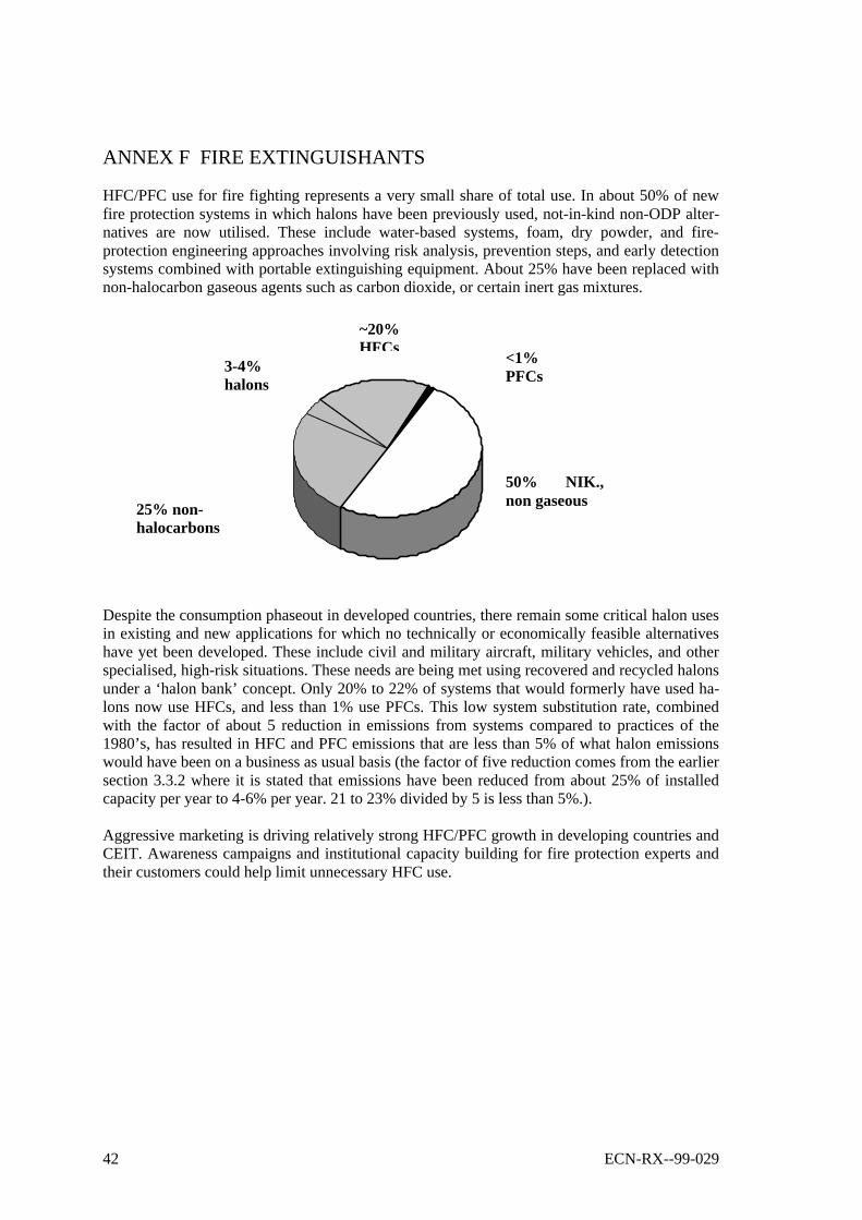
42 ECN-RX--99-029
ANNEX F FIRE EXTINGUISHANTS
HFC/PFC use for fire fighting represents a very small share of total use. In about 50% of newfire protection systems in which halons have been previously used, not-in-kind non-ODP alter-natives are now utilised. These include water-based systems, foam, dry powder, and fire-protection engineering approaches involving risk analysis, prevention steps, and early detectionsystems combined with portable extinguishing equipment. About 25% have been replaced withnon-halocarbon gaseous agents such as carbon dioxide, or certain inert gas mixtures.
Despite the consumption phaseout in developed countries, there remain some critical halon usesin existing and new applications for which no technically or economically feasible alternativeshave yet been developed. These include civil and military aircraft, military vehicles, and otherspecialised, high-risk situations. These needs are being met using recovered and recycled halonsunder a ‘halon bank’ concept. Only 20% to 22% of systems that would formerly have used ha-lons now use HFCs, and less than 1% use PFCs. This low system substitution rate, combinedwith the factor of about 5 reduction in emissions from systems compared to practices of the1980’s, has resulted in HFC and PFC emissions that are less than 5% of what halon emissionswould have been on a business as usual basis (the factor of five reduction comes from the earliersection 3.3.2 where it is stated that emissions have been reduced from about 25% of installedcapacity per year to 4-6% per year. 21 to 23% divided by 5 is less than 5%.).
Aggressive marketing is driving relatively strong HFC/PFC growth in developing countries andCEIT. Awareness campaigns and institutional capacity building for fire protection experts andtheir customers could help limit unnecessary HFC use.
50% NIK.,non gaseous
3-4%halons
~20%HFCs
<1%PFCs
25% non-halocarbons
ECN-RX--99-029 43
ANNEX G ACRONYMS
AFEAS Alternative Fluorocarbon Environmental Acceptability StudyBAU Business-As-UsualCEIT Country with Economy In TransitionCFC ChlorofluorocarbonCOPD Chronic Obstructive Pulmonary DiseaseDME DimethyletherDPI Dry Powder InhalerECN Energieonderzoek Centrum NederlandGEF Global Environment FacilityGHG Greenhouse GasGWP Global Warming PotentialHAP Hydrocarbon Aerosol PropellantHC HydrocarbonHCFC HydrochlorofluorocarbonHFC HydrofluorocarbonHFE HydrofluoroetherIPCC Intergovernmental Panel on Climate ChangeMDI Metered Dose InhalerMLF Multilateral FundMP Montreal ProtocolODP Ozone Depletion PotentialODS Ozone Depleting SubstanceOEM Original Equipment ManufacturerOEWG Open Ended Working GroupPFC PerfluorocarbonR/A/C Refrigeration and Air ConditioningTEAP Technology and Economic Assessment PanelTEWI Total Equivalent Warming ImpactTSU Technical Support UnitUNDP United Nations Development ProgrammeUNEP United Nations Environment ProgrammeUNFCCC United Nations Framework Convention on Climate ChangeUNIDO United Nations Industrial Development OrganisationVOC Volatile Organic CompoundWHO World Health Organisation

44 ECN-RX--99-029
ANNEX H LIST OF PARTICIPANTS(NAME, AFFILIATION, COUNTRY)
J.G. AbbottDow EuropeSWITZERLAND
R.S. AgarwalIndian Institute ofTechnology DelhiINDIA
Amina AliMinistry of EnvironmentMALAYSIA
Stephen AndersenUS EPA/ UNEP TEAPUSA
Steve AndersonAFCAMAUSTRALIA
Paul AshfordCaleb Management ServicesUNITED KINGDOM
Jim BakerHarrisonUSA
Marc BarreauElf AtochemFRANCE
Pierre BarthelemySolvay Fluor & DerivativeGmbHGERMANY
Don BivensDuPont FluorproductsUSA
Paul BlacklockCalorgasUNITED KINGDOM
Wolfgang BlochInfineon TechnologiesGERMANY
Philip Michael CallaghanUK DETRUNITED KINGDOM
James M. CalmEngineering ConsultantUSA
Nick CampbellICI KLEAUNITED KINGDOM
Suely CarvalhoUNDPUSA
Nandan ChirmulayUNDP WoldbankUSA
Anita CiceroIPACUSA
Marc CisnerosGreat Lakes Chemical Corp.USA
Denis ClodicEcole des MinesFRANCE
Daniel ColbourneCalor GasUNITED KINGDOM
Liz CookWorld Resources InstituteUSA
Jorge CoronaCanacintraMEXICO
Jim CrawfordTraneUSA
ECN-RX--99-029 45
James ColmanPrivate Office RT. Hon. J.Gummer MPUNITED KINGDOM
Ogunlade DavidsonUniversity of SierraLeone/RisoeDENMARK
Sukumar DevottaNational ChemicalLaboratoryINDIA
Ebel DijkstraEcozoneTHE NETHERLANDS
Jorgen FenhannRisoe/RoskildeDENMARK
Yuichi FujimotoJICOPJAPAN
Ray GluckmanMarch ConsultantsUNITED KINGDOM
Michael GraberUNEP Ozone SecrKENYA
Frans GrunchardSolvay S.A.GERMANY
Joop van HaasterenMinisterie van VROMTHE NETHERLANDS
Jochen HarnischECOFYSGERMANY
Tony HetheringtonUNMFSCANADA
Niklas HoehneUN FCCCGERMANY
Blaise HorisbergerSwiss Agency forEnvironment, Forests andLandscapeSWITSERLAND
Eliisa IrpolaFinnish EnvironmentInstituteFINLAND
Seiji IshiiJUFAJAPAN
Mike JeffsICIBELGIUM
Bob JohnsonWhirlpool CorporationUSA
Makoto KaibaraMITIJAPAN
Holger KoenigBitzer GmbHGERMANY
Fred KellerCarrier CorporationUSA
Yokoi KiyoshigeMatshushita RefrigerationCompanyJAPAN
Haruhiko KonoMITIJAPAN
Barbara Kucnerowicz-PolakState Fire ServicePOLAND
Lambert KuijpersTUE/ UNEP TEAPTHE NETHERLANDS
Li JunfengCREDP.R. CHINA
Henk Van der MaatenAllied SignalTHE NETHERLANDS
46 ECN-RX--99-029
Petra MahrenholzFederal EnvironmentalAgencyGERMANY
John MateGreenpeaceCANADA
Ian Maclaine CrossUniversity of New SouthWalesAUSTRALIA
Archie McCullochICI Chemicals & PolymersLtd.UNITED KINGDOM
E.J. McInerneyGeneral Electric CompanyUSA
Gerard MegieInst Pierre S. LaplaceFRANCE
Mack McFarlandDupont FluorproductsUSA
Leo MeyerMinistry of EnvironmentTHE NETHERLANDS
Abid MerchantDupontUSA
Fujiharu MiyazakiJapan Regrigeration &Air ConditioningJAPAN
Mohinder MalikLufthansa German AirlinesGERMANY
William MoomawIPCCUSA
Tom MorehouseInstitute for DefenseAnalysesUSA
Catalina MoslerUNEPMEXICO
Norihiro NishikawaFederation of Electric PowerCompaniesJAPAN
Sebastian OberthuerEcologicGERMANY
Toshika OhgitaInstitute for Techno-economicsJAPAN
Haruo OhnishiDaikin Industries Ltd./JRAIAJAPAN
Risto OjalaUNOPS - UNDPFINLAND
Kusuo OkiJapan Industrial Conferencefor Ozone Layer ProtectionJAPAN
John Owens3M Specialty MaterialsUSA
Per Henrik PedersenDTIDENMARK
Jill PhillipsUS EPAUSA
Frank PintoUNDPUSA
Ewald PreiseggerSolvay Fluor und DerivateGmbHGERMANY
Wiraphon RajadanuraksEnv. Ministry ThailandTHAILAND

ECN-RX--99-029 47
Sally RandUS EPAUSA
Janaka RatnasiriMinistry of Forestry andEnvironmentSRI LANKA
Gunther ReinerSulzer Friotherm LtdSWITSERLAND
Bob RussellDow Chemical CompanyUSA
Eva-Lotte B. SandinSwedish EnvironmentalProtection AgencySWEDEN
Luis SantosMinistry of EnvironmentURUGUAY
Akira SekiyaRITE/ NIMCJapan
S.M. SiahmedUNDIDOAUSTRIA
Stephan SicarsSitecGERMANY
M StampGreat Lakes Chemical Corp.UNITED KINGDOM
Takuya SuizuFederation of Electric PowerCompaniesJAPAN
Rob SwartRIVMTHE NETHERLANDS
Dennis TirpakUNFCCCGERMANY
Jim TraweekDep of State USAUSA
Jessica ValetteFriends of the EarthUSA
Pham Van ThoMin Fisheries, VietnamVIETNAM
Brian WardEurofeuUNITED KINGDOM
Masami WatanabeMitsubishi Electric Co.JAPAN
Tujibayashi YoshiyukiJAMA (Nissan)JAPAN
Yokoi YaheitoGERMANY
Dana MunUNEPFRANCE
Frank RittnerWorldbankUSA
Patrice RolletPronosolFRANCE
Per RosenqvistEur. Commission DG XIBELGIUM
Paul Wright
UNITED KINGDOM
Makoto YoshidaJAMA(Nissan)BELGIUM
Remko YbemaECN/IPCC TSU of WG IIITHE NETHERLANDS
48 ECN-RX--99-029
ANNEX I TABLE OF CONTENTS OF THE PROCEEDINGS - PAPERSPRESENTED
Introductory papers
1. Gérard Mégie The Scientific interlinks between the Montreal and theKyoto Protocols.
2. Jorgen Fenhann HFC, PFC and SF6 emission scenarios: recent develop-ments in IPCC special report on emission scenarios.
3. Mack McFarland Applications and emissions of fluorocarbon gases: past,present and prospects for the future.
4. Tony HetheringtonOmar El-Arini
The implementation of HFC based projects under themultilateral fund: developments and future trends
5. Janaka Ratnasiri The Kyoto Protocol impact on developing country HFCpolicies for implementing the Montreal protocol.
6. Frank PintoS. Si-AhmedSteve Gorman
Options for reduction of emissions of HFCs in developingcountries.
7. Ray GluckmanDuncan Yellen
Financial implications of emission reduction options forHFCs, PFCs and SF6.
Emissions and emission projections
1. Archie McCulloch Halocarbon greenhouse gas emissions during the nextcentury.
2. Eric Johnson Getting HFC/PFC emissions right: towards more robustestimates.
ECN-RX--99-029 49
Refrigeration and Air-conditioning
1. Denis Clodic Emissions from HFC-based refrigeration and A/Cequipment: historical development and future trends.
2. Donald Bivens Refrigeration and air-conditioning with reduced envi-ronmental impact.
3. James M. Calm Emissions and environmental impacts from air-conditioning and refrigeration systems.
4. CorcoranSpatzShanklandVink
HFC emission reduction options for air-conditioning andheat pump systems.
5. James Crawford Limiting the HFC emissions of chillers.
6. Yasuo Watanabe Trend in the usage of refrigerant and heat insulationfoaming agent for domestic refrigerator in Japan.
7. SekiyaMisakiBeppu
Joint research by RITE and NIMC in new refrigerants,foam blowing agents and solvents and new research onPFC use in semiconductor manufacturing.
8. ColbourneBlacklock
Limiting HFC emissions through the use of non-HFCtechnologies.
9. James Baker Mobile air-conditioning: HFC-134a emissions and emis-sion reduction strategies.
10. Guenther Reiner Reduction of greenhouse effect on refrigeration plants.
11. Stephen Sicars Potential of low GWP alternatives in refrigeration.
12. Ewald Preisegger Automotive air-conditioning impact of refrigerant onglobal warming.
13. Yoshiyuki Tujibayashi Action plan related to emission control of HFC-134a re-frigerant for automobile air-conditioning systems.
14. McInerneyHaworthJohnsonSwatkowski
Domestic refrigeration refrigerants.
15. R.S. Agarwal
16. Sukumar Devotta Indian R&AC sector: HFC future demand and emissions
17. Haruo Ohnishi-Yokoi The importance of HFC to certain refrigeration and ACuse.
18. Ian Maclaine-cross Replacement refrigerants for water chillers
19. John Maté How to limit HFC emissions? Eliminate them
50 ECN-RX--99-029
Foams, Aerosols/MDIs and Fire Extinguishants
1. Paul Ashford Considerations for the responsible use of HFCs infoams.
2. Pierre Barthelémy Contribution of HFC blowing agents to global warming,a producer’s view.
3. JohnsonHaworthMcInerneySwatkowski
HFC blowing agents for domestic refrigerator insulatingfoam.
4. Seiji Ishii Blowing Agent in PU Foam Industry in Japan
5. JeffsDe Vos
Zero ODP blowing agent options for rigid polyurethaneinsulating foams.
6. Paul Ashford Emissions from foams- predicting, monitoring, reportingand reducing.
7. Robert Russell Extruded Polystyrene Foam (XPS) - Technical options& decision making criteria
Solvents, Aerosols/MDI
1. Nick Campbell Technical, pesticide, cosmetic, convenience, and noveltyaerosol products.
2. Abid Merchant Alternative to ODS Solvents and emission reductiontechnologies
3. John Owens Segregated hydrofluoroethers: low GWP alternatives toHFCs and PFCs.
4. Paul Wright Patient care issues in HFC emissions policy.
Fire Extinguishants
1. Barbara Kucnerowitcz-Polak Fluorocarbon alternatives in the fire protection sector.
2. CisnerosRobin
An integrated approach to achieve low environmentalimpact in the special hazards fire suppression industry.
3. Brian Ward Climate change and environmental protection in theEuropean Union. The need for fluorocarbons in fireprotection.
ECN-RX--99-029 51
PFC and SF6 emissions from manufacturing
1. RandOttingerBranscome
Opportunities for the reduction of HFC-23 emissions fromthe production of HCFC-22.
2. RolletMicozzi
SF6 recycling.
3. HarnischWingJacobyPrinn
Primary aluminium production: climate policy, emissionsand costs.
4. Laurie BeuPaul Brown
Use and emissions mitigation of PFC, HFC and SF6 in thesemiconductor industry
5. Wolfgang Bloch
6. Takuya Suizu Partnership Activities for SF6 gas emission reduction fromgas insulated electrical equipment in Japan.
Implementation of non-ODP projects in developing countries
1. Frans Grunchard Mitigation of the global warming impact of fluorocarbons indeveloping countries.
2. SharmaBagai
Interface of Montreal protocol with Kyoto protocol: someissues.
3. Cathalina Mosler Developing countries concerns on the use of HFCs – LatinAmerica and the Caribbean
4. Wiraphon Rajadanuraks Leadership companies in Thailand and elsewhere chooseHFCs to replace CFCs
Government policies to limit emissions
1. Per Henrik Pedersen Ways of reducing consumption and emission of potentgreenhouse gases (HFCs, PFCs and SF6) in the Nordiccountries
2. Petra Mahrenholz Possible emission reduction measures for HFCs in Germany
3. Haruhiko Kono Promotion of measures to limit HFC, PFC and SF6 emis-sions in Japan


