Page 1
MEF 50 © The MEF Forum 2014. Any reproduction of this document, or any portion thereof, shall contain the
following statement: "Reproduced with permission of the MEF Forum." No user of this document is
authorized to modify any of the information contained herein.
Service Operations
Guidelines
MEF 50
Carrier Ethernet Service Lifecycle Process Model
December 2014
Page 2
MEF 50 © The MEF Forum 2014. Any reproduction of this document, or any portion thereof, shall contain the
following statement: "Reproduced with permission of the MEF Forum." No user of this document is
authorized to modify any of the information contained herein.
Disclaimer
The information in this publication is freely available for reproduction and use by any re-
cipient and is believed to be accurate as of its publication date. Such information is sub-
ject to change without notice and the MEF Forum (MEF) is not responsible for any er-
rors. The MEF does not assume responsibility to update or correct any information in
this publication. No representation or warranty, expressed or implied, is made by the
MEF concerning the completeness, accuracy, or applicability of any information con-
tained herein and no liability of any kind shall be assumed by the MEF as a result of reli-
ance upon such information.
The information contained herein is intended to be used without modification by the re-
cipient or user of this document. The MEF is not responsible or liable for any modifica-
tions to this document made by any other party.
The receipt or any use of this document or its contents does not in any way create, by im-
plication or otherwise:
a) any express or implied license or right to or under any patent, copyright, trademark
or trade secret rights held or claimed by any MEF member company which are or
may be associated with the ideas, techniques, concepts or expressions contained
herein; nor
b) any warranty or representation that any MEF member companies will announce
any product(s) and/or service(s) related thereto, or if such announcements are made,
that such announced product(s) and/or service(s) embody any or all of the ideas,
technologies, or concepts contained herein; nor
c) any form of relationship between any MEF member companies and the recipient or
user of this document.
Implementation or use of specific Metro Ethernet standards or recommendations and
MEF specifications and guidelines will be voluntary, and no company shall be obliged to
implement them by virtue of participation in the MEF Forum. The MEF is a non-profit
international organization accelerating industry cooperation on Metro Ethernet technol-
ogy. The MEF does not, expressly or otherwise, endorse or promote any specific products
or services.
© The MEF Forum 2014. All Rights Reserved.
Page 3
Carrier Ethernet Service Lifecycle Process Model
MEF 50 © The MEF Forum 2014. Any reproduction of this document, or any portion thereof, shall contain the
following statement: "Reproduced with permission of the MEF Forum." No user of this document is
authorized to modify any of the information contained herein.
Page i
Table of Contents
1. List of Contributing Member Companies .........................................................................1
2. Abstract ..............................................................................................................................1
3. Terminology and Acronyms...............................................................................................1
4. Scope ...................................................................................................................................5
5. Compliance Levels ..............................................................................................................5
6. Introduction ........................................................................................................................5
7. Product Lifecycle Management .........................................................................................8
7.1 Market Analysis and Product Strategy .............................................................................8 7.2 Product Design .............................................................................................................. 13 7.3 Service and Resource Design ........................................................................................ 20 7.4 Establish Relationship between Service Provider and Access Provider .......................... 25 7.5 Launch Products ............................................................................................................ 31
8. Service Operations Lifecycle Management ..................................................................... 33
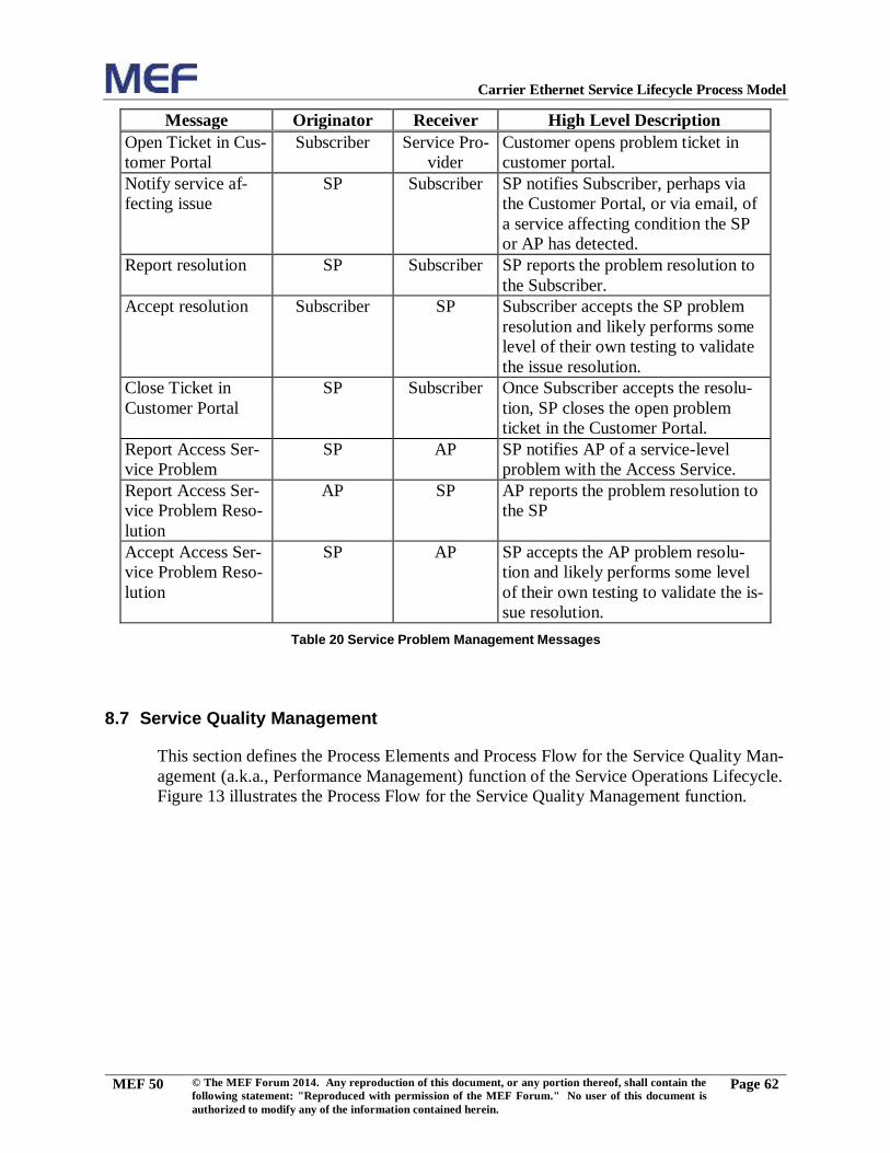
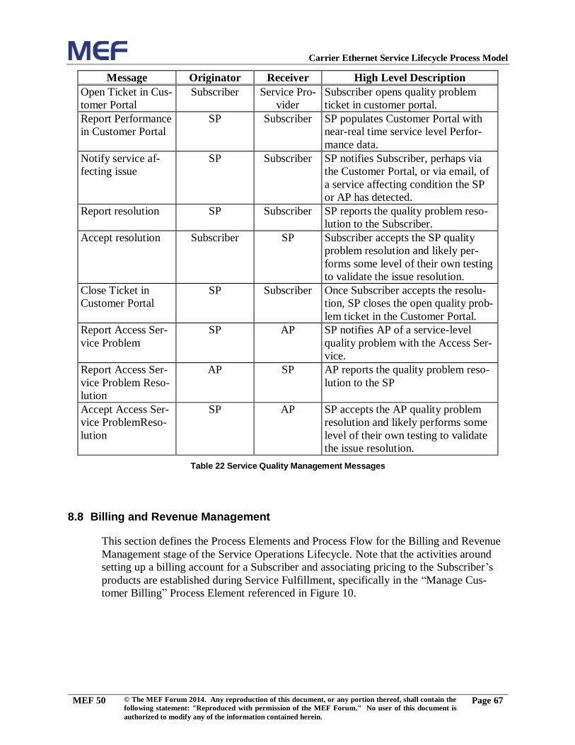
8.1 Marketing Fulfillment Response .................................................................................... 34 8.2 Sales Proposal and Feasibility ....................................................................................... 37 8.3 Capture Customer Order ................................................................................................ 43 8.4 Service Configuration and Activation ............................................................................ 46 8.5 End-to-End Service Testing ........................................................................................... 53 8.6 Service Problem Management ....................................................................................... 58 8.7 Service Quality Management......................................................................................... 62 8.8 Billing and Revenue Management ................................................................................. 67 8.9 Terminate Customer Relationship ................................................................................. 75
9. References ......................................................................................................................... 76
10. Acknowledgements ......................................................................................................... 77
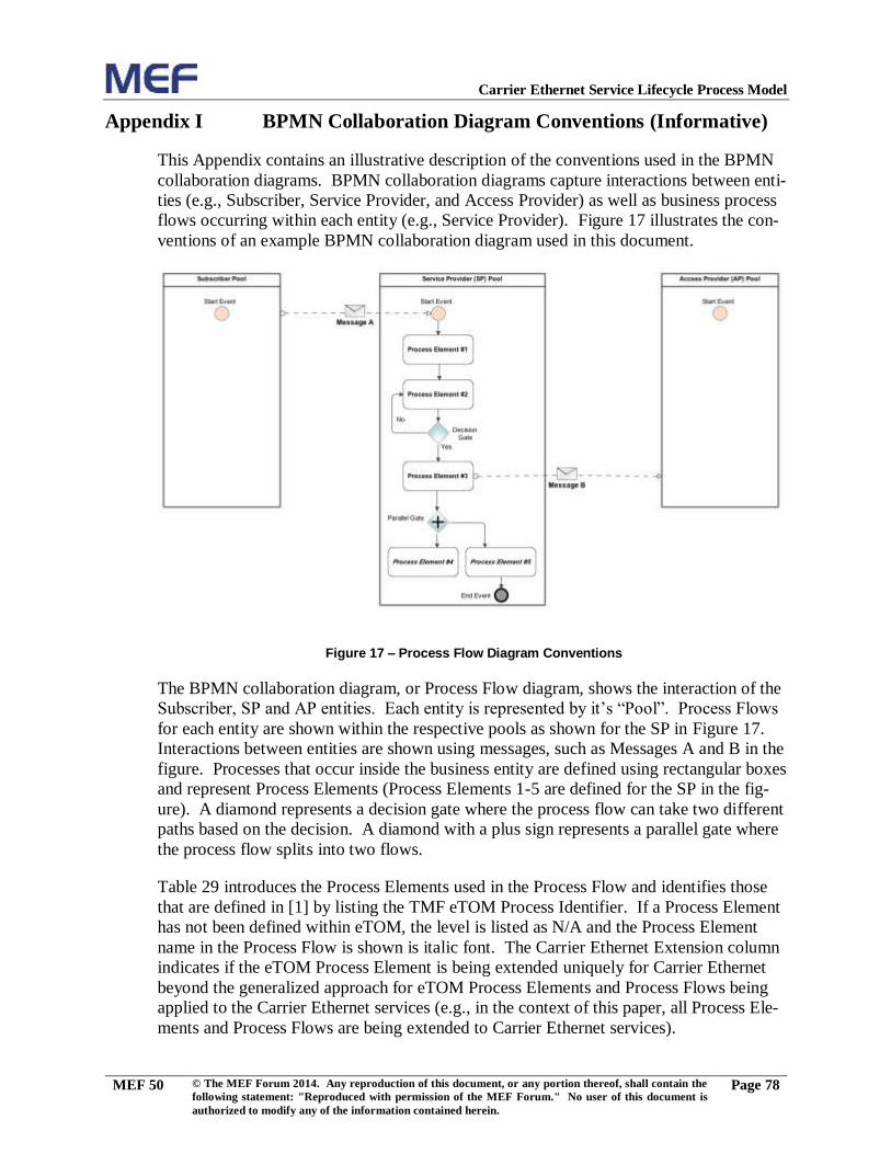
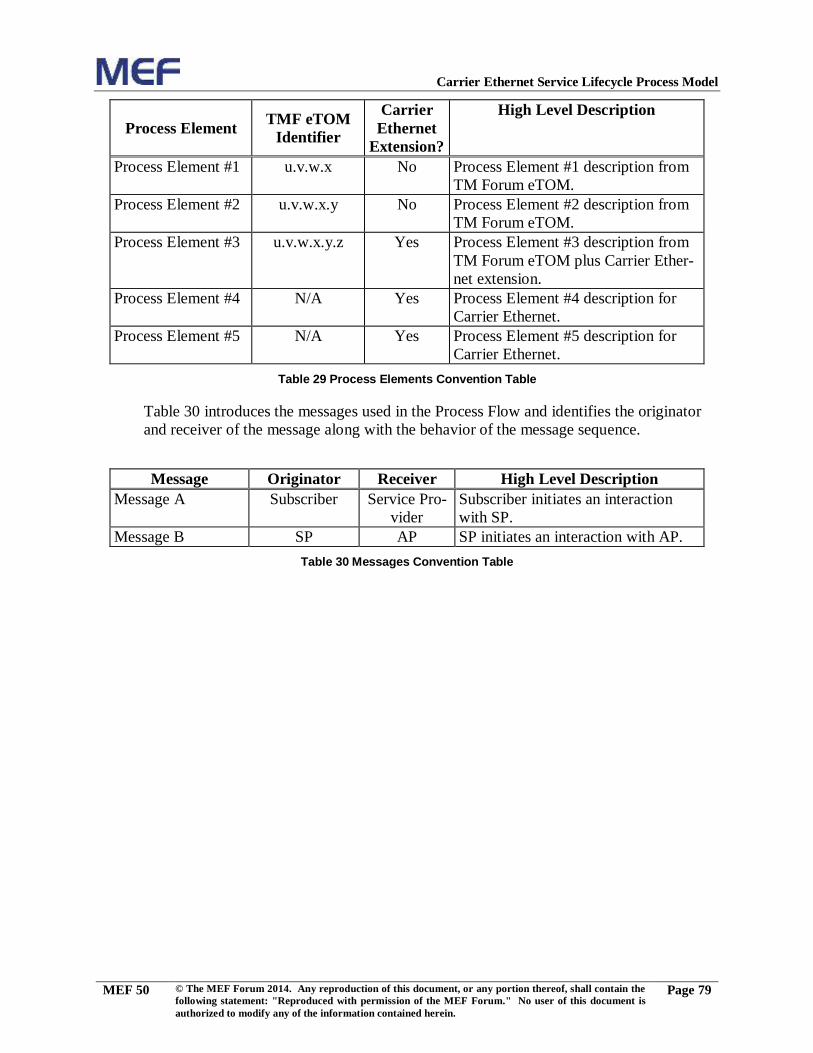
Appendix I BPMN Collaboration Diagram Conventions (Informative) ............................ 78
List of Figures
Figure 1 – Product and Service Operations Lifecycle Stages .......................................................8 Figure 2 – Market Analysis and Product Strategy Process Flow ................................................ 10 Figure 3 – Product Design Process Flow ................................................................................... 15 Figure 4 – Service and Resource Design Process Flow .............................................................. 21 Figure 5 – Establish Relationship between Service Provider and Access Provider ..................... 26 Figure 6 – Launch Products Process Flow ................................................................................. 32 Figure 7 – Marketing Fulfillment Response Process Flow ......................................................... 34 Figure 8 – Sales Proposal & Feasibility Process Flow ............................................................... 38 Figure 9 – Capture Customer Order Process Flow ..................................................................... 44 Figure 10 – Service Configuration and Activation Process Flow ............................................... 47 Figure 11 – End-to-End Service Testing Process Flow .............................................................. 54
Page 4
Carrier Ethernet Service Lifecycle Process Model
MEF 50 © The MEF Forum 2014. Any reproduction of this document, or any portion thereof, shall contain the
following statement: "Reproduced with permission of the MEF Forum." No user of this document is
authorized to modify any of the information contained herein.
Page ii
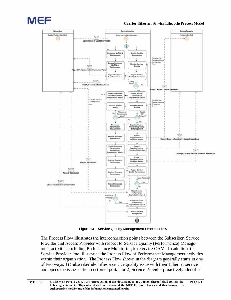
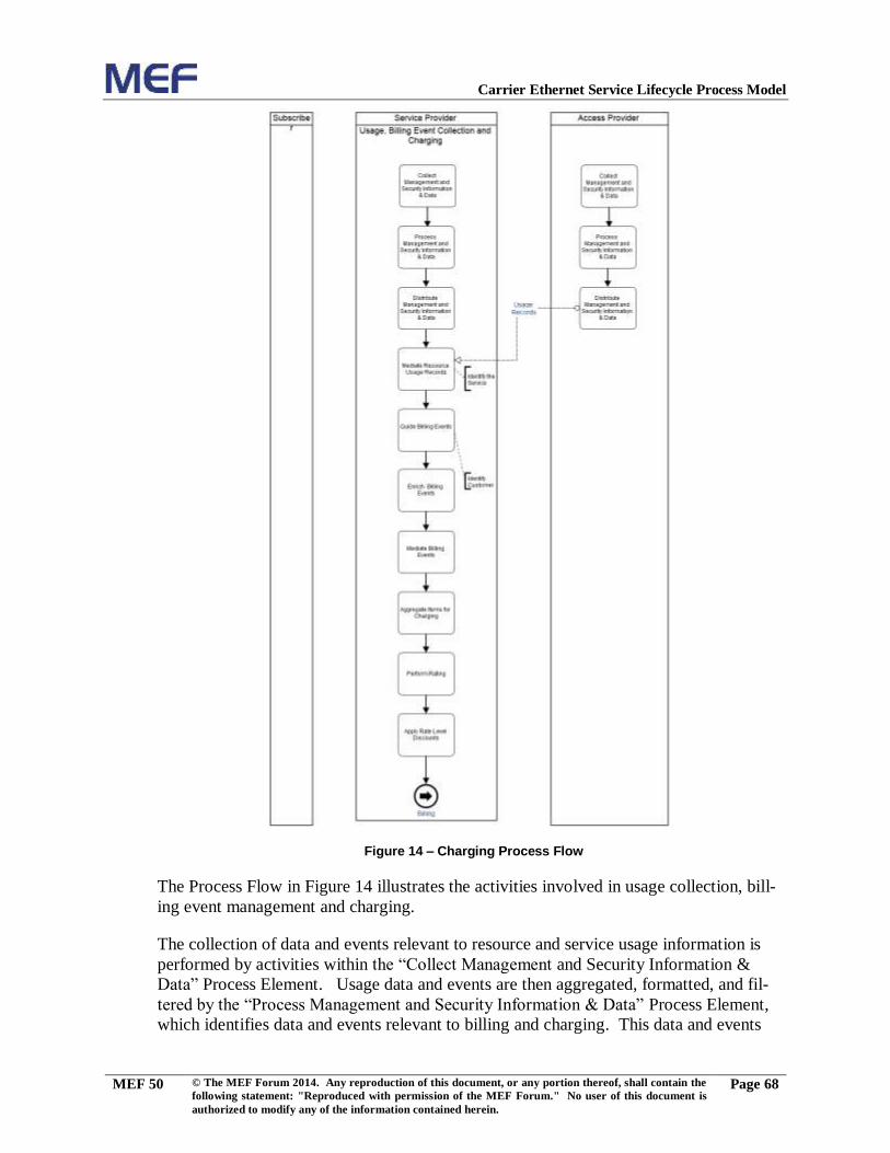
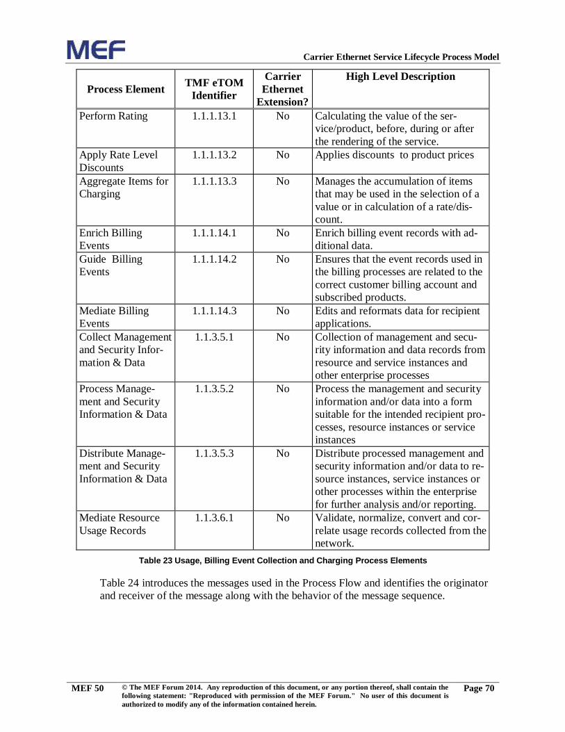
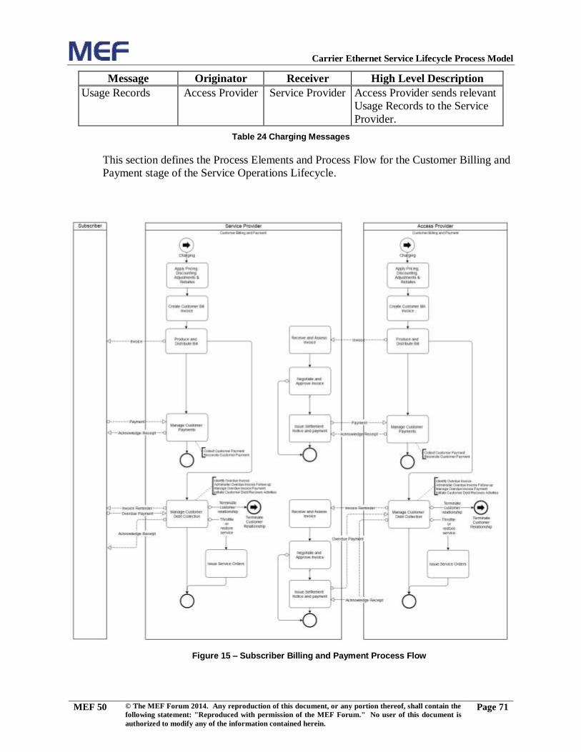
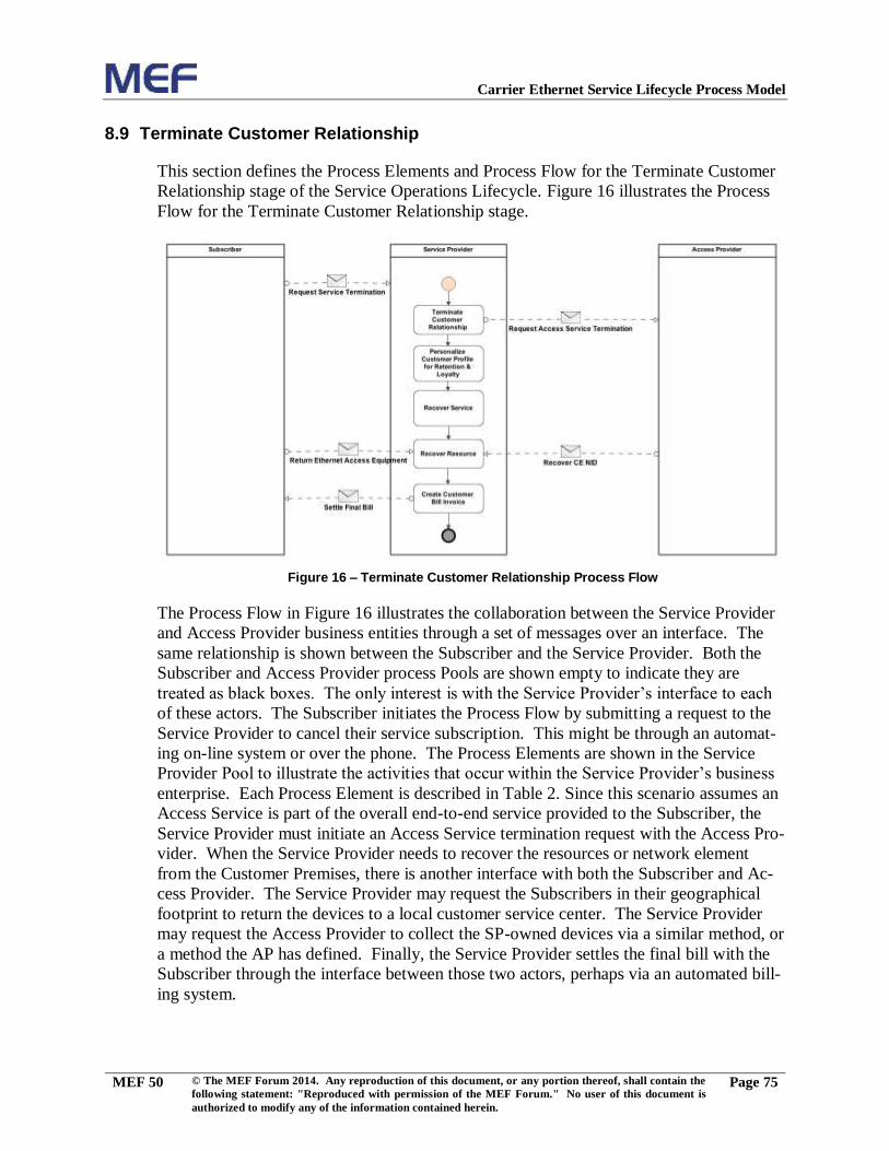
Figure 12 – Service Problem Management Process Flow ........................................................... 58 Figure 13 – Service Quality Management Process Flow ............................................................ 63 Figure 14 – Charging Process Flow ........................................................................................... 68 Figure 15 – Subscriber Billing and Payment Process Flow ........................................................ 71 Figure 16 – Terminate Customer Relationship Process Flow ..................................................... 75 Figure 17 – Process Flow Diagram Conventions ....................................................................... 78
List of Tables
Table 1 Contributing Member Companies ...................................................................................1 Table 2 Terminology and Acronyms ...........................................................................................5 Table 3 Market Analysis and Product Strategy Process Elements .............................................. 13 Table 4 Product Design Process Elements ................................................................................. 20 Table 5 Service and Resource Design Process Elements ............................................................ 25 Table 6 Establish Relationship between Service Provider and Access Provider Process Elements
.......................................................................................................................................... 30 Table 7 Establish Relationship between Service Provider and Access Provider Messages ......... 31 Table 8 Launch Products Process Elements ............................................................................... 33 Table 9 Marketing Fulfillment Response Process Elements ....................................................... 36 Table 10 Marketing Fulfillment Response Messages ................................................................. 37 Table 11 Sales Proposal and Feasibility Process Elements ......................................................... 42 Table 12 Sales Proposal and Feasibility Messages ..................................................................... 43 Table 13 Capture Customer Order Process Elements ................................................................. 45 Table 14 Capture Customer Order Messages ............................................................................. 46 Table 15 Service Configuration and Activation Process Elements ............................................. 52 Table 16 Service Configuration and Activation Messages ......................................................... 53 Table 17 End-to-End Service Testing Process Elements ............................................................ 57 Table 18 End-to-End Service Testing Messages ........................................................................ 57 Table 19 Service Problem Management Process Elements ........................................................ 61 Table 20 Service Problem Management Messages .................................................................... 62 Table 21 Service Quality Management Process Elements .......................................................... 66 Table 22 Service Quality Management Messages ...................................................................... 67 Table 23 Usage, Billing Event Collection and Charging Process Elements ................................ 70 Table 24 Charging Messages ..................................................................................................... 71 Table 25 Subscriber Billing and Payment Process Elements ...................................................... 73 Table 26 Subscriber Billing and Payment Messages .................................................................. 74 Table 27 Terminate Customer Relationship Process Elements ................................................... 76 Table 28 Terminate Customer Relationship Messages ............................................................... 76 Table 29 Process Elements Convention Table ........................................................................... 79 Table 30 Messages Convention Table ....................................................................................... 79
Page 5
Carrier Ethernet Service Lifecycle Process Model
MEF 50 © The MEF Forum 2014. Any reproduction of this document, or any portion thereof, shall contain the
following statement: "Reproduced with permission of the MEF Forum." No user of this document is
authorized to modify any of the information contained herein.
Page 1
1. List of Contributing Member Companies
The following Member companies of the MEF participated in the development of this
document and have requested to be included in this list.
Member Company
Allstream
Ericsson
EXFO
Fujitsu
Oracle Communications
PCCW Global
Table 1 Contributing Member Companies
2. Abstract
This document documents a process model for the generic Carrier Ethernet service lifecy-
cle, including Service Operations Lifecycle management and Product Lifecycle manage-
ment. It establishes a foundation for specifications developed by the MEF Service Opera-
tions Committee. Such documents should reference the foundational material in this doc-
ument.
The process model is composed of a series of Process Flows woven together to form the
Carrier Ethernet service lifecycle. Each Process Flow is composed using Process Ele-
ments that define processes performed within a Service Provider’s organization. At the
core, a single Process describes functional activities or tasks required to deliver results or
outputs. The Process Flows are graphically defined using Business Process Model and
Notation (BPMN) and represent the Process Elements in an end-to-end or through Pro-
cess view across the Service Provider’s business as well as between different organiza-
tions such as the Service Provider and Wholesale partner or end Subscriber. Therefore,
each Process Flow examines some specific scenario in which the Processes achieve an
overall business purpose for the Service Provider (e.g., ordering handling of Carrier
Ethernet services). The TeleManagement Forum’s Business Process Framework, also re-
ferred to as the enhanced Telecom Operations Map (eTOM) [1], has an extensive defini-
tion of Process Elements and decomposition of these Process Elements applicable to a
Service Provider’s business. As such, this document leverages these Process Element
definitions as the building blocks to creating the Carrier Ethernet Process Flows. In a few
instances, Process Elements required for Carrier Ethernet did not exist in the eTOM
framework and have been defined in this document.
3. Terminology and Acronyms
This section defines the terms used in this document. In many cases, the normative defi-
nitions to terms are found in other documents. In these cases, the third column is used to
provide the reference that is controlling, in other MEF or external documents.
Page 6
Carrier Ethernet Service Lifecycle Process Model
MEF 50 © The MEF Forum 2014. Any reproduction of this document, or any portion thereof, shall contain the
following statement: "Reproduced with permission of the MEF Forum." No user of this document is
authorized to modify any of the information contained herein.
Page 2
Page 7
Carrier Ethernet Service Lifecycle Process Model
MEF 50 © The MEF Forum 2014. Any reproduction of this document, or any portion thereof, shall contain the
following statement: "Reproduced with permission of the MEF Forum." No user of this document is
authorized to modify any of the information contained herein.
Page 3
Term Definition Reference
Access Provider A CEN Operator that offers the Ethernet Access Ser-
vice type.
MEF 33 [5]
BPMN Business Process Model and Notation or Business
Process Modeling Notation
BPMN 2 [9]
Business Process
Model and Notation
Business Process Model and Notation (BPMN), also
known as Business Process Modeling Notation, is a
graphical representation for specifying business pro-
cesses and process flows in a business process
model. BPMN is a standard for business process
modeling that provides a graphical notation for spec-
ifying business processes and process flows in a
business process diagram.
BPMN 2 [9]
Carrier Ethernet Net-
work
A network from a Service Provider or network oper-
ator supporting the MEF service and architecture
models.
MEF 12.1 [3]
CEN Carrier Ethernet Network MEF 12.1 [3]
eTOM enhanced Telecom Operations Map (a.k.a. Business
Process Framework)
TMF GB921P [8]
Process A Process describes a systematic, sequenced set of
functional activities that deliver a specified result. In
other words, a Process is a sequence of related activ-
ities or tasks required to deliver results or outputs.
TMF GB921CP
[7]
Process Element Process Elements can be considered as the building
blocks or components, which are used to ‘assemble’
end-to-end business Processes. A BPMN Process El-
ement defines a process performed in an organiza-
tion.
TMF GB921CP
[7]
Process Flow A Process Flow graphically represents the behavior
of Process Elements in an "end-to-end" or "through"
Process view across the business (i.e., Enterprise).
Such Process Flows are not constrained to bridge
across the entire Enterprise, they can have any scope
that is meaningful and helpful to analyze (e.g., Ser-
vice Activation Testing). Thus, Process Flows exam-
ine some specific scenario in which the processes
achieve an overall business purpose. The MEF is us-
ing the BPMN2 notation for documenting Process
Flows.
TMF GB921P [8]
Page 8
Carrier Ethernet Service Lifecycle Process Model
MEF 50 © The MEF Forum 2014. Any reproduction of this document, or any portion thereof, shall contain the
following statement: "Reproduced with permission of the MEF Forum." No user of this document is
authorized to modify any of the information contained herein.
Page 4
Term Definition Reference
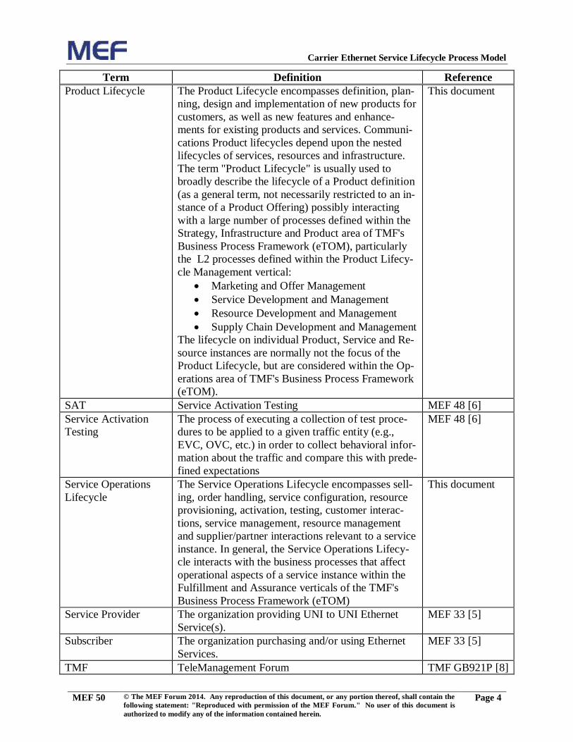
Product Lifecycle The Product Lifecycle encompasses definition, plan-
ning, design and implementation of new products for
customers, as well as new features and enhance-
ments for existing products and services. Communi-
cations Product lifecycles depend upon the nested
lifecycles of services, resources and infrastructure.
The term "Product Lifecycle" is usually used to
broadly describe the lifecycle of a Product definition
(as a general term, not necessarily restricted to an in-
stance of a Product Offering) possibly interacting
with a large number of processes defined within the
Strategy, Infrastructure and Product area of TMF's
Business Process Framework (eTOM), particularly
the L2 processes defined within the Product Lifecy-
cle Management vertical:
Marketing and Offer Management
Service Development and Management
Resource Development and Management
Supply Chain Development and Management
The lifecycle on individual Product, Service and Re-
source instances are normally not the focus of the
Product Lifecycle, but are considered within the Op-
erations area of TMF's Business Process Framework
(eTOM).
This document
SAT Service Activation Testing MEF 48 [6]
Service Activation
Testing
The process of executing a collection of test proce-
dures to be applied to a given traffic entity (e.g.,
EVC, OVC, etc.) in order to collect behavioral infor-
mation about the traffic and compare this with prede-
fined expectations
MEF 48 [6]
Service Operations
Lifecycle
The Service Operations Lifecycle encompasses sell-
ing, order handling, service configuration, resource
provisioning, activation, testing, customer interac-
tions, service management, resource management
and supplier/partner interactions relevant to a service
instance. In general, the Service Operations Lifecy-
cle interacts with the business processes that affect
operational aspects of a service instance within the
Fulfillment and Assurance verticals of the TMF's
Business Process Framework (eTOM)
This document
Service Provider The organization providing UNI to UNI Ethernet
Service(s).
MEF 33 [5]
Subscriber The organization purchasing and/or using Ethernet
Services.
MEF 33 [5]
TMF TeleManagement Forum TMF GB921P [8]
Page 9
Carrier Ethernet Service Lifecycle Process Model
MEF 50 © The MEF Forum 2014. Any reproduction of this document, or any portion thereof, shall contain the
following statement: "Reproduced with permission of the MEF Forum." No user of this document is
authorized to modify any of the information contained herein.
Page 5
Table 2 Terminology and Acronyms
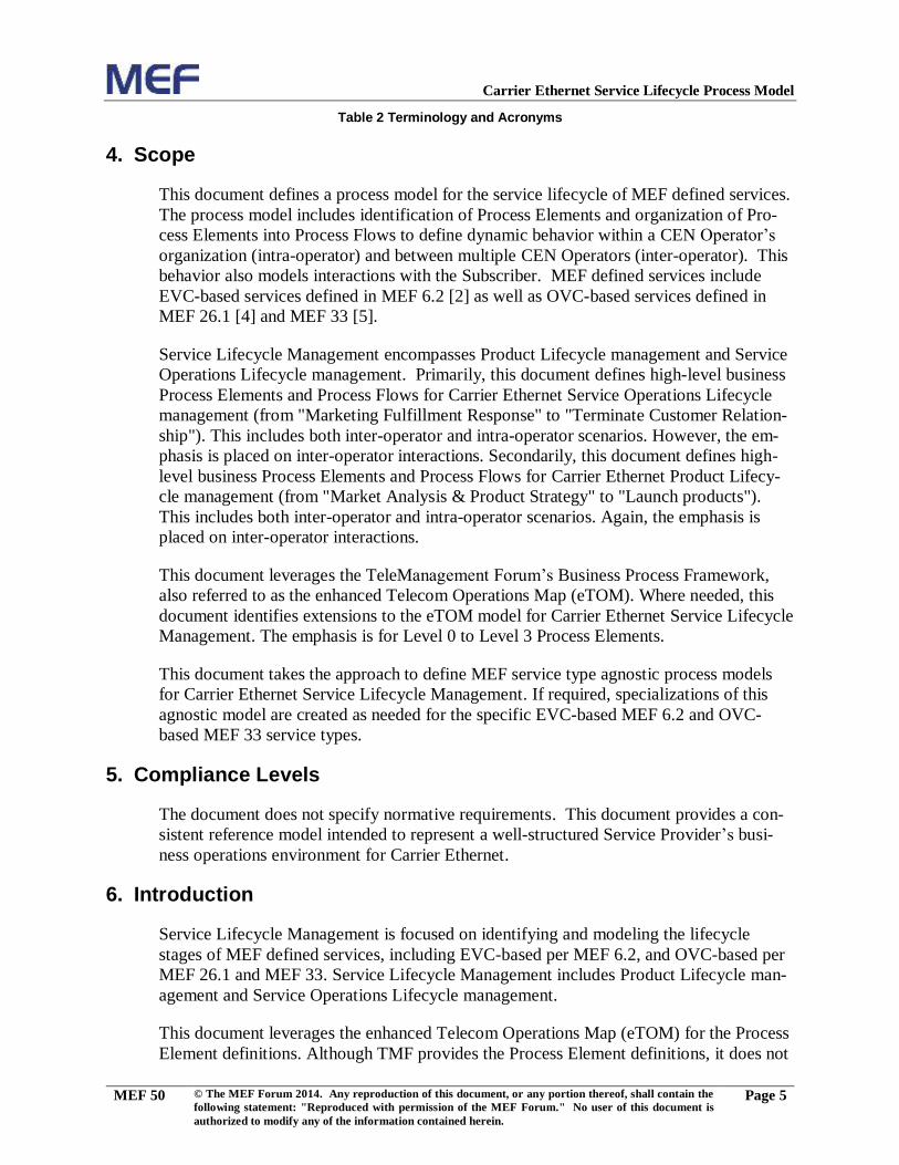
4. Scope
This document defines a process model for the service lifecycle of MEF defined services.
The process model includes identification of Process Elements and organization of Pro-
cess Elements into Process Flows to define dynamic behavior within a CEN Operator’s
organization (intra-operator) and between multiple CEN Operators (inter-operator). This
behavior also models interactions with the Subscriber. MEF defined services include
EVC-based services defined in MEF 6.2 [2] as well as OVC-based services defined in
MEF 26.1 [4] and MEF 33 [5].
Service Lifecycle Management encompasses Product Lifecycle management and Service
Operations Lifecycle management. Primarily, this document defines high-level business
Process Elements and Process Flows for Carrier Ethernet Service Operations Lifecycle
management (from "Marketing Fulfillment Response" to "Terminate Customer Relation-
ship"). This includes both inter-operator and intra-operator scenarios. However, the em-
phasis is placed on inter-operator interactions. Secondarily, this document defines high-
level business Process Elements and Process Flows for Carrier Ethernet Product Lifecy-
cle management (from "Market Analysis & Product Strategy" to "Launch products").
This includes both inter-operator and intra-operator scenarios. Again, the emphasis is
placed on inter-operator interactions.
This document leverages the TeleManagement Forum’s Business Process Framework,
also referred to as the enhanced Telecom Operations Map (eTOM). Where needed, this
document identifies extensions to the eTOM model for Carrier Ethernet Service Lifecycle
Management. The emphasis is for Level 0 to Level 3 Process Elements.
This document takes the approach to define MEF service type agnostic process models
for Carrier Ethernet Service Lifecycle Management. If required, specializations of this
agnostic model are created as needed for the specific EVC-based MEF 6.2 and OVC-
based MEF 33 service types.
5. Compliance Levels
The document does not specify normative requirements. This document provides a con-
sistent reference model intended to represent a well-structured Service Provider’s busi-
ness operations environment for Carrier Ethernet.
6. Introduction
Service Lifecycle Management is focused on identifying and modeling the lifecycle
stages of MEF defined services, including EVC-based per MEF 6.2, and OVC-based per
MEF 26.1 and MEF 33. Service Lifecycle Management includes Product Lifecycle man-
agement and Service Operations Lifecycle management.
This document leverages the enhanced Telecom Operations Map (eTOM) for the Process
Element definitions. Although TMF provides the Process Element definitions, it does not
Page 10
Carrier Ethernet Service Lifecycle Process Model
MEF 50 © The MEF Forum 2014. Any reproduction of this document, or any portion thereof, shall contain the
following statement: "Reproduced with permission of the MEF Forum." No user of this document is
authorized to modify any of the information contained herein.
Page 6
provide the comprehensive Process Flows for service definitions. Therefore, this docu-
ment defines Process Flows in the context of Carrier Ethernet service definitions and
where necessary identifies extensions to the eTOM model for Process Element defini-
tions.
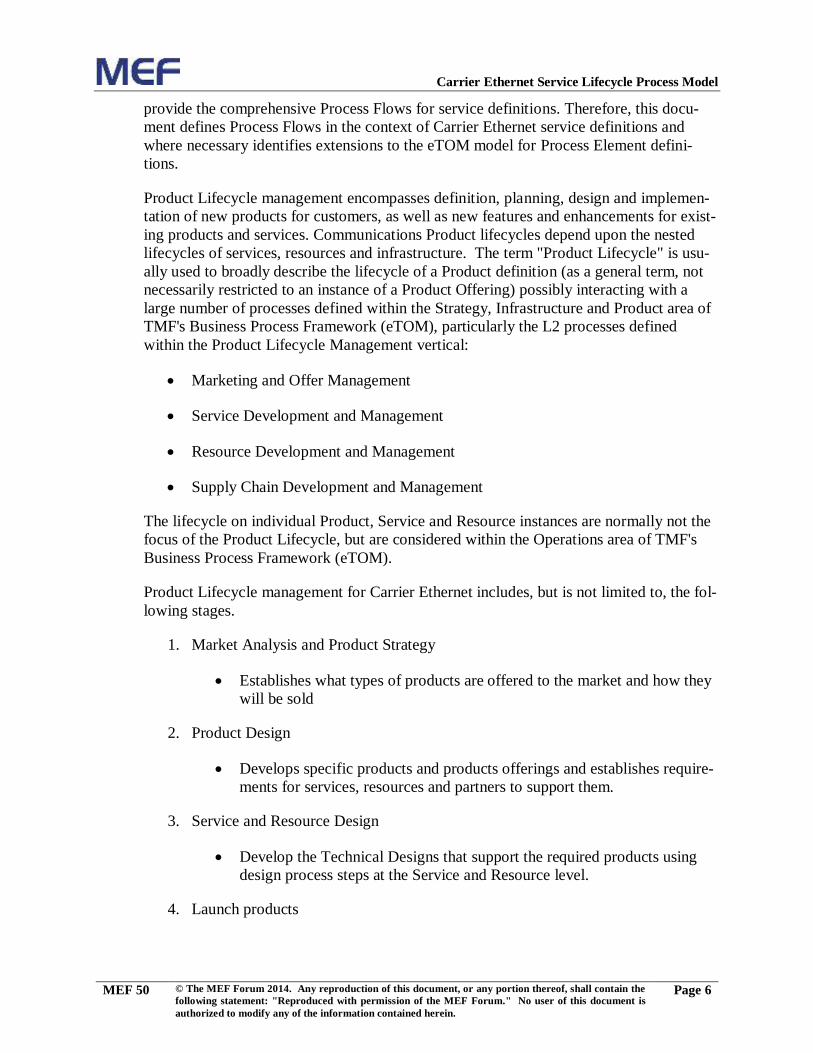
Product Lifecycle management encompasses definition, planning, design and implemen-
tation of new products for customers, as well as new features and enhancements for exist-
ing products and services. Communications Product lifecycles depend upon the nested
lifecycles of services, resources and infrastructure. The term "Product Lifecycle" is usu-
ally used to broadly describe the lifecycle of a Product definition (as a general term, not
necessarily restricted to an instance of a Product Offering) possibly interacting with a
large number of processes defined within the Strategy, Infrastructure and Product area of
TMF's Business Process Framework (eTOM), particularly the L2 processes defined
within the Product Lifecycle Management vertical:
Marketing and Offer Management
Service Development and Management
Resource Development and Management
Supply Chain Development and Management
The lifecycle on individual Product, Service and Resource instances are normally not the
focus of the Product Lifecycle, but are considered within the Operations area of TMF's
Business Process Framework (eTOM).
Product Lifecycle management for Carrier Ethernet includes, but is not limited to, the fol-
lowing stages.
1. Market Analysis and Product Strategy
Establishes what types of products are offered to the market and how they
will be sold
2. Product Design
Develops specific products and products offerings and establishes require-
ments for services, resources and partners to support them.
3. Service and Resource Design
Develop the Technical Designs that support the required products using
design process steps at the Service and Resource level.
4. Launch products
Page 11
Carrier Ethernet Service Lifecycle Process Model
MEF 50 © The MEF Forum 2014. Any reproduction of this document, or any portion thereof, shall contain the
following statement: "Reproduced with permission of the MEF Forum." No user of this document is
authorized to modify any of the information contained herein.
Page 7
Makes products available to the market and ensures that orders for the
products can be successfully fulfilled.
The Service Operations Lifecycle encompasses selling, order handling, service configura-
tion, resource provisioning, activation, testing, customer interactions, service manage-
ment, resource management and supplier/partner interactions relevant to a service in-
stance. In general, the Service Operations Lifecycle interacts with the business processes
that affect operational aspects of a service instance within the Fulfillment and Assurance
verticals of the TMF's Business Process Framework (eTOM).
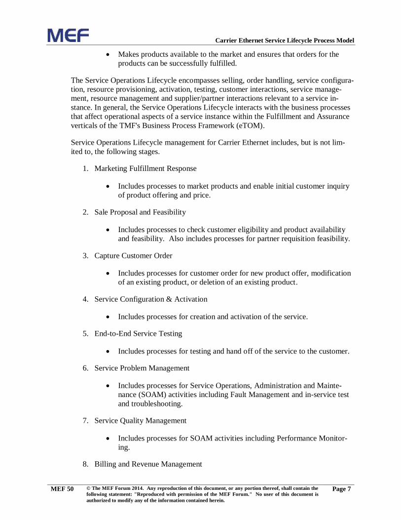
Service Operations Lifecycle management for Carrier Ethernet includes, but is not lim-
ited to, the following stages.
1. Marketing Fulfillment Response
Includes processes to market products and enable initial customer inquiry
of product offering and price.
2. Sale Proposal and Feasibility
Includes processes to check customer eligibility and product availability
and feasibility. Also includes processes for partner requisition feasibility.
3. Capture Customer Order
Includes processes for customer order for new product offer, modification
of an existing product, or deletion of an existing product.
4. Service Configuration & Activation
Includes processes for creation and activation of the service.
5. End-to-End Service Testing
Includes processes for testing and hand off of the service to the customer.
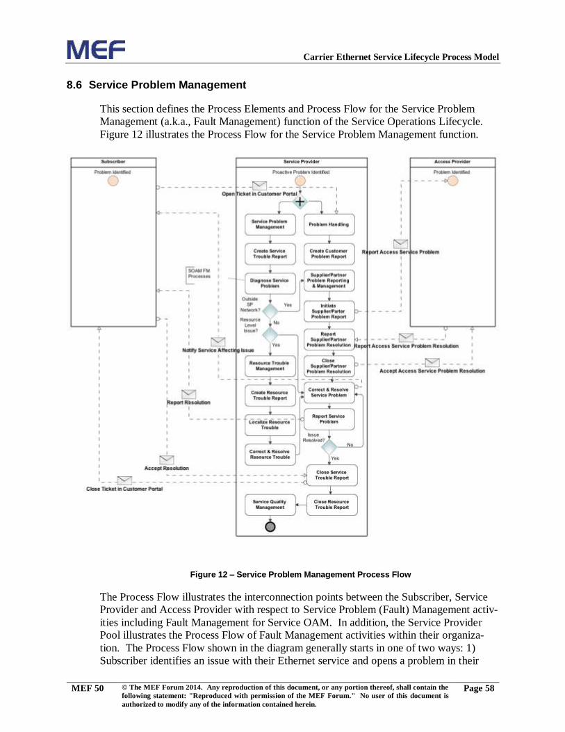
6. Service Problem Management
Includes processes for Service Operations, Administration and Mainte-
nance (SOAM) activities including Fault Management and in-service test
and troubleshooting.
7. Service Quality Management
Includes processes for SOAM activities including Performance Monitor-
ing.
8. Billing and Revenue Management
Page 12
Carrier Ethernet Service Lifecycle Process Model
MEF 50 © The MEF Forum 2014. Any reproduction of this document, or any portion thereof, shall contain the
following statement: "Reproduced with permission of the MEF Forum." No user of this document is
authorized to modify any of the information contained herein.
Page 8
Includes processes for usage monitoring, charging, billing and managing
customer payments
9. Terminate Customer Relationship
Includes processes for ending the relationship with the customer.
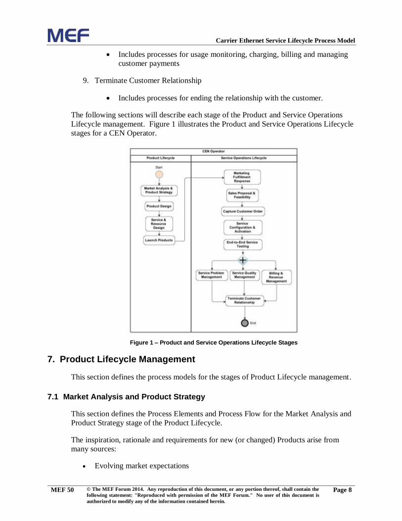
The following sections will describe each stage of the Product and Service Operations
Lifecycle management. Figure 1 illustrates the Product and Service Operations Lifecycle
stages for a CEN Operator.
Figure 1 – Product and Service Operations Lifecycle Stages
7. Product Lifecycle Management
This section defines the process models for the stages of Product Lifecycle management.
7.1 Market Analysis and Product Strategy
This section defines the Process Elements and Process Flow for the Market Analysis and
Product Strategy stage of the Product Lifecycle.
The inspiration, rationale and requirements for new (or changed) Products arise from
many sources:
Evolving market expectations
Page 13
Carrier Ethernet Service Lifecycle Process Model
MEF 50 © The MEF Forum 2014. Any reproduction of this document, or any portion thereof, shall contain the
following statement: "Reproduced with permission of the MEF Forum." No user of this document is
authorized to modify any of the information contained herein.
Page 9
Decisions to address specific market segments
Standards work within MEF that formalizes and standardizes products and service
variants tuned for specific market segments such as Carrier Backhaul or Cloud
Access
The standardization of popular variants of "custom solutions" to improve the op-
erational efficiency of delivering and maintaining them
New technology, new vendor equipment and new paradigms in the network that
provide new capabilities in the network to be monetized
Leveraging existing infrastructure and technologies to extract value by exposing
these existing capabilities as eternal product offerings
Addressing competitive threats - responding to the products offered by competi-
tors. This encompasses pricing, bundling, technology, geographic footprint
The success (or failure) of existing products
The overall strategy may be constrained by several factors including:
Existing infrastructure
Available suppliers/partners
Page 14
Carrier Ethernet Service Lifecycle Process Model
MEF 50 © The MEF Forum 2014. Any reproduction of this document, or any portion thereof, shall contain the
following statement: "Reproduced with permission of the MEF Forum." No user of this document is
authorized to modify any of the information contained herein.
Page 10
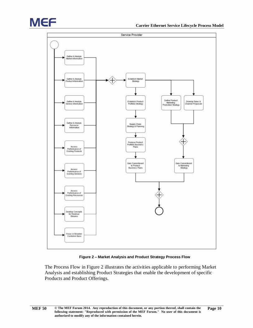
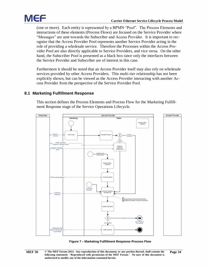
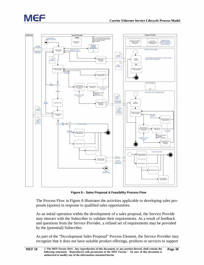
Figure 2 – Market Analysis and Product Strategy Process Flow
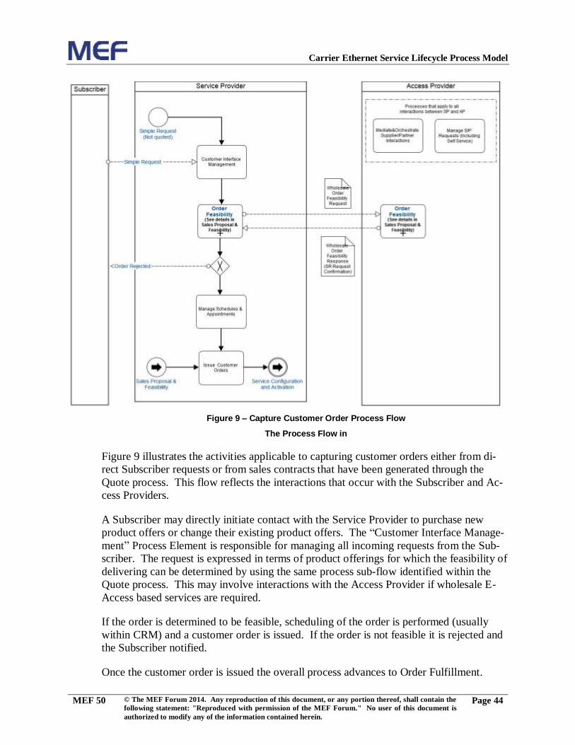
The Process Flow in Figure 2 illustrates the activities applicable to performing Market
Analysis and establishing Product Strategies that enable the development of specific
Products and Product Offerings.
Page 15
Carrier Ethernet Service Lifecycle Process Model
MEF 50 © The MEF Forum 2014. Any reproduction of this document, or any portion thereof, shall contain the
following statement: "Reproduced with permission of the MEF Forum." No user of this document is
authorized to modify any of the information contained herein.
Page 11
There are a wide variety of inputs that contribute to establishing an overall market strat-
egy. These inputs are obtained through specific activities focused on gathering and ana-
lyzing appropriate input and insights. The types of inputs include market information,
new product ideas, new service ideas and new resource ideas, as well as the assessment
of how existing implementations of products, services and resources are performing. In
addition, analysis of potential revenue streams and the customer base may reveal addi-
tional opportunities.
Once a market strategy is established, this will provide essential input into Product Port-
folio strategy, which in turn will affect a Supply Chain Strategy with respect to “Make or
Buy” decisions. Once these overall strategies are defined, Product Portfolio Business
Plans may be established and commitments made to move forward.
In parallel to these activities are the developments of Marketing Promotion strategies and
Sales proposals. These are important components of an overall Market Strategy.
When organizational commitment is made for both the Product Business Plans and the
Market Strategy, work may begin on the development of specific Product Definitions.
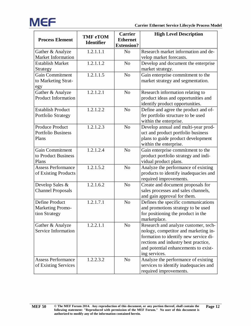
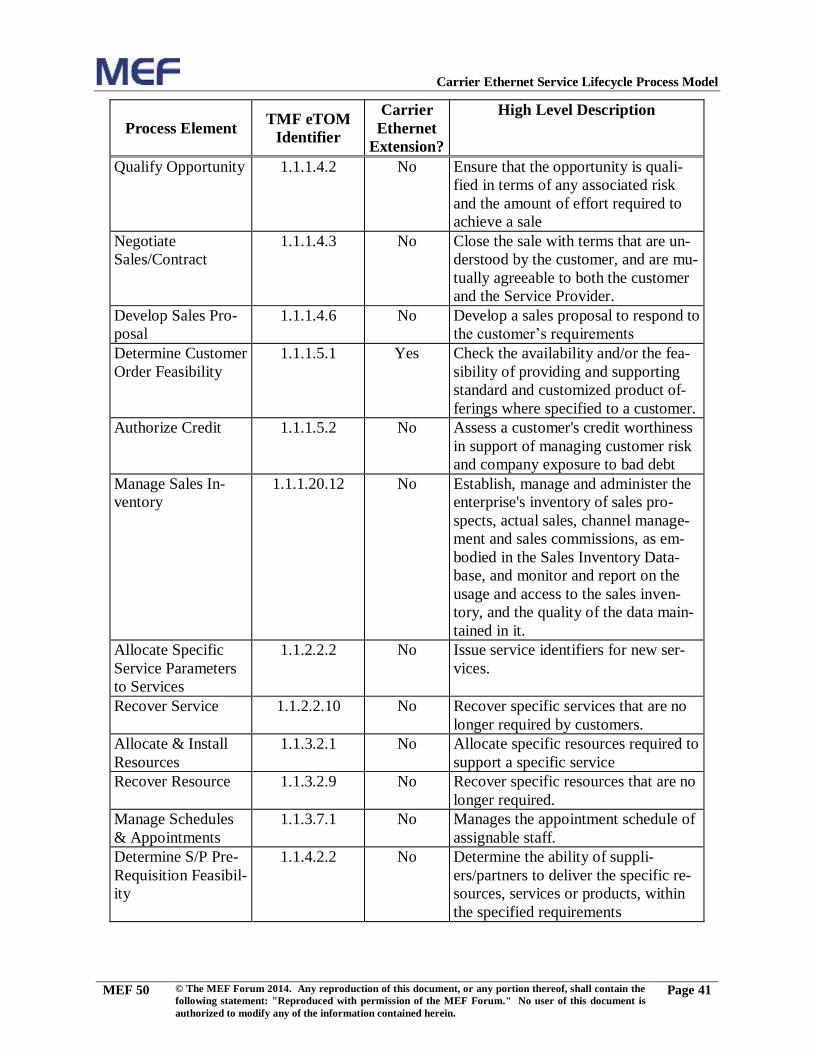
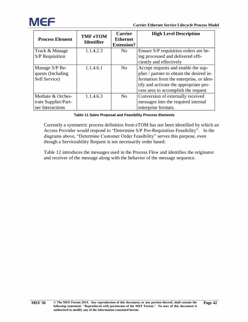
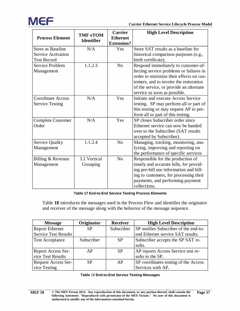
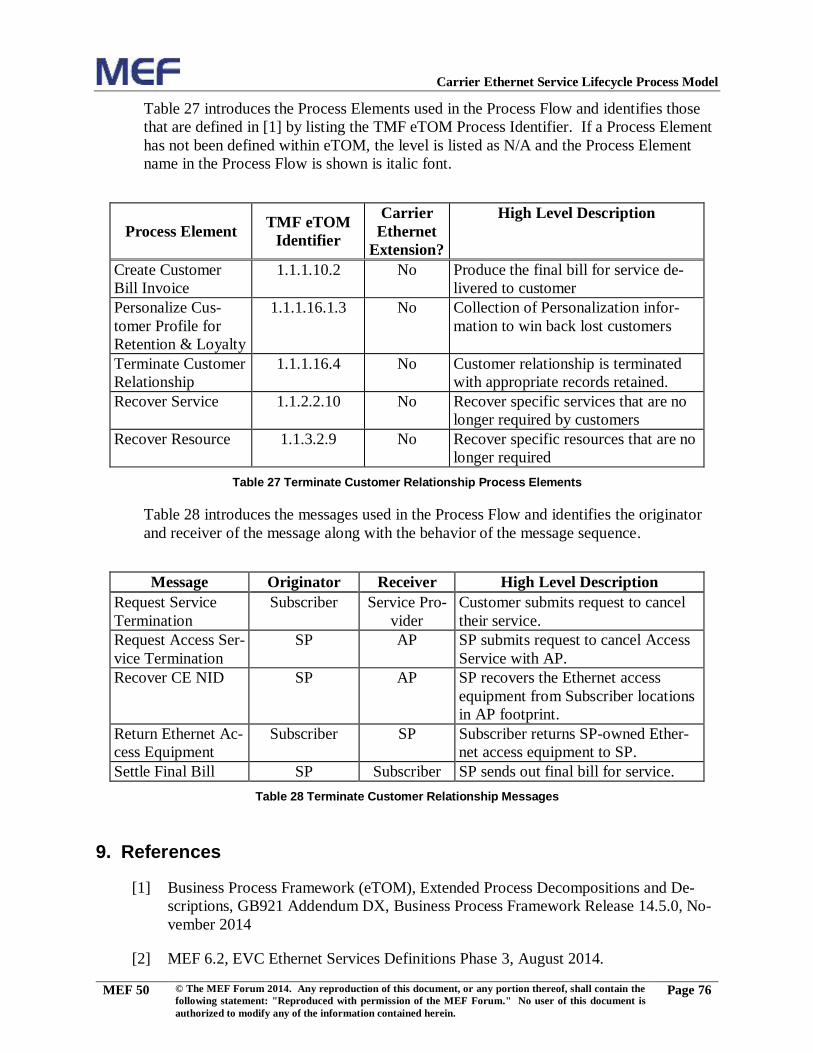
Table 3 introduces the Process Elements used in the Process Flow and identifies those
that are defined in [1] by listing the TMF eTOM Process Identifier. If a Process Element
has not been defined within eTOM, the level is listed as N/A and the Process Element
name in the Process Flow is shown in italic font.
Page 16
Carrier Ethernet Service Lifecycle Process Model
MEF 50 © The MEF Forum 2014. Any reproduction of this document, or any portion thereof, shall contain the
following statement: "Reproduced with permission of the MEF Forum." No user of this document is
authorized to modify any of the information contained herein.
Page 12
Process Element TMF eTOM
Identifier
Carrier
Ethernet
Extension?
High Level Description
Gather & Analyze
Market Information
1.2.1.1.1
No Research market information and de-
velop market forecasts.
Establish Market
Strategy
1.2.1.1.2
No Develop and document the enterprise
market strategy.
Gain Commitment
to Marketing Strat-
egy
1.2.1.1.5
No Gain enterprise commitment to the
market strategy and segmentation.
Gather & Analyze
Product Information
1.2.1.2.1
No Research information relating to
product ideas and opportunities and
identify product opportunities.
Establish Product
Portfolio Strategy
1.2.1.2.2
No Define and agree the product and of-
fer portfolio structure to be used
within the enterprise.
Produce Product
Portfolio Business
Plans
1.2.1.2.3
No Develop annual and multi-year prod-
uct and product portfolio business
plans to guide product development
within the enterprise.
Gain Commitment
to Product Business
Plans
1.2.1.2.4
No Gain enterprise commitment to the
product portfolio strategy and indi-
vidual product plans.
Assess Performance
of Existing Products
1.2.1.5.2
No Analyze the performance of existing
products to identify inadequacies and
required improvements.
Develop Sales &
Channel Proposals
1.2.1.6.2
No Create and document proposals for
sales processes and sales channels,
and gain approval for them.
Define Product
Marketing Promo-
tion Strategy
1.2.1.7.1
No Defines the specific communications
and promotions strategy to be used
for positioning the product in the
marketplace.
Gather & Analyze
Service Information
1.2.2.1.1
No Research and analyze customer, tech-
nology, competitor and marketing in-
formation to identify new service di-
rections and industry best practice,
and potential enhancements to exist-
ing services.
Assess Performance
of Existing Services
1.2.2.3.2
No Analyze the performance of existing
services to identify inadequacies and
required improvements.
Page 17
Carrier Ethernet Service Lifecycle Process Model
MEF 50 © The MEF Forum 2014. Any reproduction of this document, or any portion thereof, shall contain the
following statement: "Reproduced with permission of the MEF Forum." No user of this document is
authorized to modify any of the information contained herein.
Page 13
Process Element TMF eTOM
Identifier
Carrier
Ethernet
Extension?
High Level Description
Gather & Analyze
Resource Infor-
mation
1.2.3.1.1
No Research and analyze customer, tech-
nology, competitor and marketing in-
formation to identify new resource
requirements and industry resource
capabilities and availability.
Assess Performance
of Existing Re-
sources
1.2.3.3.2
No Analyze the performance of existing
resources to identify inadequacies
and required improvements.
Supply Chain Strat-
egy & Planning
1.2.4.1
No Develop the Supply Chain strategies
and policies of the enterprise.
Develop Concepts
for Revenue
Streams
1.3.1.2.1
No Develop concepts for new revenue
streams, and diversification of reve-
nue streams.
Focus or Broaden
Customer Base
1.3.1.2.2
No Focus or broaden the customer base
via investigating new markets, as
well as different products and ser-
vices for the enterprise.
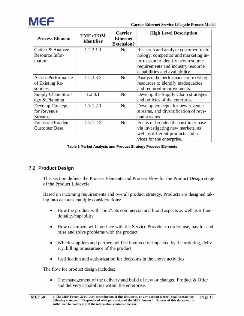
Table 3 Market Analysis and Product Strategy Process Elements
7.2 Product Design
This section defines the Process Elements and Process Flow for the Product Design stage
of the Product Lifecycle.
Based on incoming requirements and overall product strategy, Products are designed tak-
ing into account multiple considerations:
How the product will "look": its commercial and brand aspects as well as it func-
tionality/capability
How customers will interface with the Service Provider to order, use, pay for and
raise and solve problems with the product
Which suppliers and partners will be involved or impacted by the ordering, deliv-
ery, billing or assurance of the product
Justification and authorization for decisions in the above activities
The flow for product design includes:
The management of the delivery and build of new or changed Product & Offer
and delivery capabilities within the enterprise.
Page 18
Carrier Ethernet Service Lifecycle Process Model
MEF 50 © The MEF Forum 2014. Any reproduction of this document, or any portion thereof, shall contain the
following statement: "Reproduced with permission of the MEF Forum." No user of this document is
authorized to modify any of the information contained herein.
Page 14
"Product Capability" delivery has been included in scope and has been interpreted
to include many activities representing "readiness" activities defined in the "Oper-
ations" side of eTOM.
It is important to note that the flows described below are defined from the perspective
of the Service Provider. While the Service Provider is establishing/modifying their
Product, Service and Resource definitions, the Access Provider is merely providing
existing “product offerings” that are being incorporated into the Service Provider’s
Product or Service definitions. Defining the Access Provider’s Products, Services
and Resources will be achieved by the Access Provider acting in the role of Service
Provider in these flows.
Page 19
Carrier Ethernet Service Lifecycle Process Model
MEF 50 © The MEF Forum 2014. Any reproduction of this document, or any portion thereof, shall contain the
following statement: "Reproduced with permission of the MEF Forum." No user of this document is
authorized to modify any of the information contained herein.
Page 15
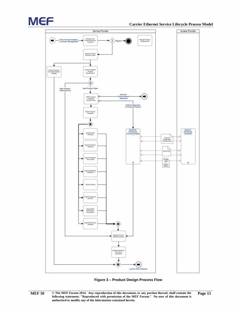
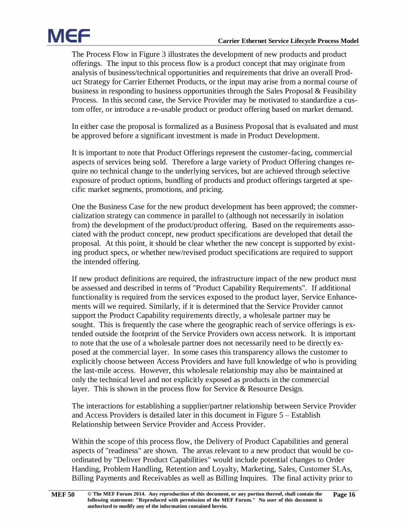
Figure 3 – Product Design Process Flow
Page 20
Carrier Ethernet Service Lifecycle Process Model
MEF 50 © The MEF Forum 2014. Any reproduction of this document, or any portion thereof, shall contain the
following statement: "Reproduced with permission of the MEF Forum." No user of this document is
authorized to modify any of the information contained herein.
Page 16
The Process Flow in Figure 3 illustrates the development of new products and product
offerings. The input to this process flow is a product concept that may originate from
analysis of business/technical opportunities and requirements that drive an overall Prod-
uct Strategy for Carrier Ethernet Products, or the input may arise from a normal course of
business in responding to business opportunities through the Sales Proposal & Feasibility
Process. In this second case, the Service Provider may be motivated to standardize a cus-
tom offer, or introduce a re-usable product or product offering based on market demand.
In either case the proposal is formalized as a Business Proposal that is evaluated and must
be approved before a significant investment is made in Product Development.
It is important to note that Product Offerings represent the customer-facing, commercial
aspects of services being sold. Therefore a large variety of Product Offering changes re-
quire no technical change to the underlying services, but are achieved through selective
exposure of product options, bundling of products and product offerings targeted at spe-
cific market segments, promotions, and pricing.
One the Business Case for the new product development has been approved; the commer-
cialization strategy can commence in parallel to (although not necessarily in isolation
from) the development of the product/product offering. Based on the requirements asso-
ciated with the product concept, new product specifications are developed that detail the
proposal. At this point, it should be clear whether the new concept is supported by exist-
ing product specs, or whether new/revised product specifications are required to support
the intended offering.
If new product definitions are required, the infrastructure impact of the new product must
be assessed and described in terms of "Product Capability Requirements". If additional
functionality is required from the services exposed to the product layer, Service Enhance-
ments will we required. Similarly, if it is determined that the Service Provider cannot
support the Product Capability requirements directly, a wholesale partner may be
sought. This is frequently the case where the geographic reach of service offerings is ex-
tended outside the footprint of the Service Providers own access network. It is important
to note that the use of a wholesale partner does not necessarily need to be directly ex-
posed at the commercial layer. In some cases this transparency allows the customer to
explicitly choose between Access Providers and have full knowledge of who is providing
the last-mile access. However, this wholesale relationship may also be maintained at
only the technical level and not explicitly exposed as products in the commercial
layer. This is shown in the process flow for Service & Resource Design.
The interactions for establishing a supplier/partner relationship between Service Provider
and Access Providers is detailed later in this document in Figure 5 – Establish
Relationship between Service Provider and Access Provider.
Within the scope of this process flow, the Delivery of Product Capabilities and general
aspects of "readiness" are shown. The areas relevant to a new product that would be co-
ordinated by "Deliver Product Capabilities" would include potential changes to Order
Handing, Problem Handling, Retention and Loyalty, Marketing, Sales, Customer SLAs,
Billing Payments and Receivables as well as Billing Inquires. The final activity prior to
Page 21
Carrier Ethernet Service Lifecycle Process Model
MEF 50 © The MEF Forum 2014. Any reproduction of this document, or any portion thereof, shall contain the
following statement: "Reproduced with permission of the MEF Forum." No user of this document is
authorized to modify any of the information contained herein.
Page 17
handover to operations is the exposure of the product as appropriate new or updated prod-
uct offerings in the Product Catalog (i.e. Product Offering Inventory).
After appropriate sets of Product Offerings have been exposed, the project can be handed
over to Operations. This hand-over may involve trials and POCs to ensure that the prod-
uct is operating as expected from both technical and commercial perspectives.
When handover is successfully completed the new product will be launched following the
process flow for "Launch Products".
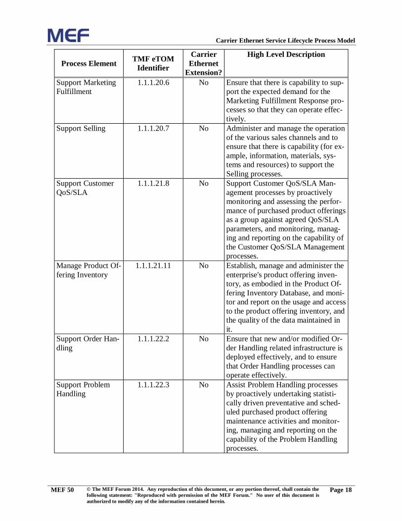
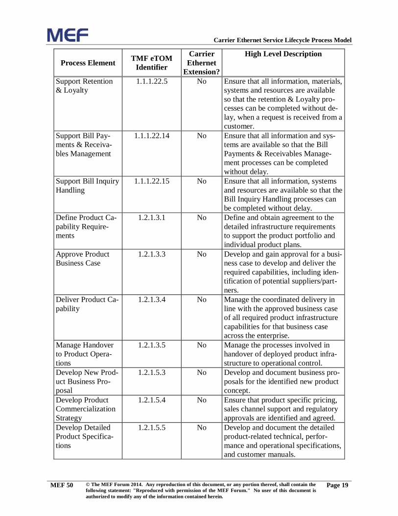
Table 4 documents the Process Elements used in the Process Flow and identifies those
that are defined in [1] by listing the TMF eTOM Process Identifier. If a Process Element
has not been defined within eTOM, the level is listed as N/A and the Process Element
name in the Process Flow is shown in italic font.
Page 22
Carrier Ethernet Service Lifecycle Process Model
MEF 50 © The MEF Forum 2014. Any reproduction of this document, or any portion thereof, shall contain the
following statement: "Reproduced with permission of the MEF Forum." No user of this document is
authorized to modify any of the information contained herein.
Page 18
Process Element TMF eTOM
Identifier
Carrier
Ethernet
Extension?
High Level Description
Support Marketing
Fulfillment
1.1.1.20.6
No Ensure that there is capability to sup-
port the expected demand for the
Marketing Fulfillment Response pro-
cesses so that they can operate effec-
tively.
Support Selling 1.1.1.20.7
No Administer and manage the operation
of the various sales channels and to
ensure that there is capability (for ex-
ample, information, materials, sys-
tems and resources) to support the
Selling processes.
Support Customer
QoS/SLA
1.1.1.21.8
No Support Customer QoS/SLA Man-
agement processes by proactively
monitoring and assessing the perfor-
mance of purchased product offerings
as a group against agreed QoS/SLA
parameters, and monitoring, manag-
ing and reporting on the capability of
the Customer QoS/SLA Management
processes.
Manage Product Of-
fering Inventory
1.1.1.21.11 No Establish, manage and administer the
enterprise's product offering inven-
tory, as embodied in the Product Of-
fering Inventory Database, and moni-
tor and report on the usage and access
to the product offering inventory, and
the quality of the data maintained in
it.
Support Order Han-
dling
1.1.1.22.2
No Ensure that new and/or modified Or-
der Handling related infrastructure is
deployed effectively, and to ensure
that Order Handling processes can
operate effectively.
Support Problem
Handling
1.1.1.22.3
No Assist Problem Handling processes
by proactively undertaking statisti-
cally driven preventative and sched-
uled purchased product offering
maintenance activities and monitor-
ing, managing and reporting on the
capability of the Problem Handling
processes.
Page 23
Carrier Ethernet Service Lifecycle Process Model
MEF 50 © The MEF Forum 2014. Any reproduction of this document, or any portion thereof, shall contain the
following statement: "Reproduced with permission of the MEF Forum." No user of this document is
authorized to modify any of the information contained herein.
Page 19
Process Element TMF eTOM
Identifier
Carrier
Ethernet
Extension?
High Level Description
Support Retention
& Loyalty
1.1.1.22.5
No Ensure that all information, materials,
systems and resources are available
so that the retention & Loyalty pro-
cesses can be completed without de-
lay, when a request is received from a
customer.
Support Bill Pay-
ments & Receiva-
bles Management
1.1.1.22.14
No Ensure that all information and sys-
tems are available so that the Bill
Payments & Receivables Manage-
ment processes can be completed
without delay.
Support Bill Inquiry
Handling
1.1.1.22.15
No Ensure that all information, systems
and resources are available so that the
Bill Inquiry Handling processes can
be completed without delay.
Define Product Ca-
pability Require-
ments
1.2.1.3.1
No Define and obtain agreement to the
detailed infrastructure requirements
to support the product portfolio and
individual product plans.
Approve Product
Business Case
1.2.1.3.3
No Develop and gain approval for a busi-
ness case to develop and deliver the
required capabilities, including iden-
tification of potential suppliers/part-
ners.
Deliver Product Ca-
pability
1.2.1.3.4
No Manage the coordinated delivery in
line with the approved business case
of all required product infrastructure
capabilities for that business case
across the enterprise.
Manage Handover
to Product Opera-
tions
1.2.1.3.5 No Manage the processes involved in
handover of deployed product infra-
structure to operational control.
Develop New Prod-
uct Business Pro-
posal
1.2.1.5.3
No Develop and document business pro-
posals for the identified new product
concept.
Develop Product
Commercialization
Strategy
1.2.1.5.4
No Ensure that product specific pricing,
sales channel support and regulatory
approvals are identified and agreed.
Develop Detailed
Product Specifica-
tions
1.2.1.5.5
No Develop and document the detailed
product-related technical, perfor-
mance and operational specifications,
and customer manuals.
Page 24
Carrier Ethernet Service Lifecycle Process Model
MEF 50 © The MEF Forum 2014. Any reproduction of this document, or any portion thereof, shall contain the
following statement: "Reproduced with permission of the MEF Forum." No user of this document is
authorized to modify any of the information contained herein.
Page 20
Process Element TMF eTOM
Identifier
Carrier
Ethernet
Extension?
High Level Description
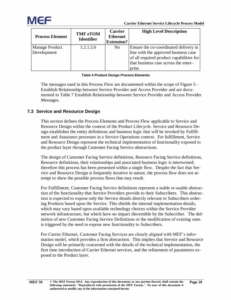
Manage Product
Development
1.2.1.5.6
No Ensure the co-coordinated delivery in
line with the approved business case
of all required product capabilities for
that business case across the enter-
prise.
Table 4 Product Design Process Elements
The messages used in this Process Flow are documented within the scope of Figure 5 –
Establish Relationship between Service Provider and Access Provider and are docu-
mented in Table 7 Establish Relationship between Service Provider and Access Provider
Messages.
7.3 Service and Resource Design
This section defines the Process Elements and Process Flow applicable to Service and
Resource Design within the context of the Product Lifecycle. Service and Resource De-
sign establishes the entity definitions and business logic that will be invoked by Fulfill-
ment and Assurance processes in a Service Operations context. For fulfillment, Service
and Resource Design represent the technical implementation of functionality exposed to
the product layer through Customer Facing Service abstractions.
The design of Customer Facing Service definitions, Resource Facing Service definitions,
Resource definitions, their relationships and associated business logic is intertwined;
therefore this process has been presented within a single flow. Despite the fact that Ser-
vice and Resource Design is frequently iterative in nature, the process flow does not at-
tempt to show the possible process flows that may result.
For Fulfillment, Customer Facing Service definitions represent a stable re-usable abstrac-
tion of the functionality that Service Providers provide to their Subscribers. This abstrac-
tion is expected to expose only the Service details directly relevant to Subscribers order-
ing Products based upon the Service. This shields the internal implementation details,
which may vary based upon available technology choices within the Service Provider
network infrastructure, but which have no impact discernible by the Subscriber. The def-
inition of new Customer Facing Service Definitions or the modification of existing ones
is triggered by the need to expose new functionality to Subscribers.
For Carrier Ethernet, Customer Facing Services are closely aligned with MEF’s infor-
mation model, which provides a firm abstraction. This implies that Service and Resource
Design will be primarily concerned with the details of the technical implementation, the
first time introduction of Carrier Ethernet services, and the refinement of parameters ex-
posed to the Product layer.
Page 25
Carrier Ethernet Service Lifecycle Process Model
MEF 50 © The MEF Forum 2014. Any reproduction of this document, or any portion thereof, shall contain the
following statement: "Reproduced with permission of the MEF Forum." No user of this document is
authorized to modify any of the information contained herein.
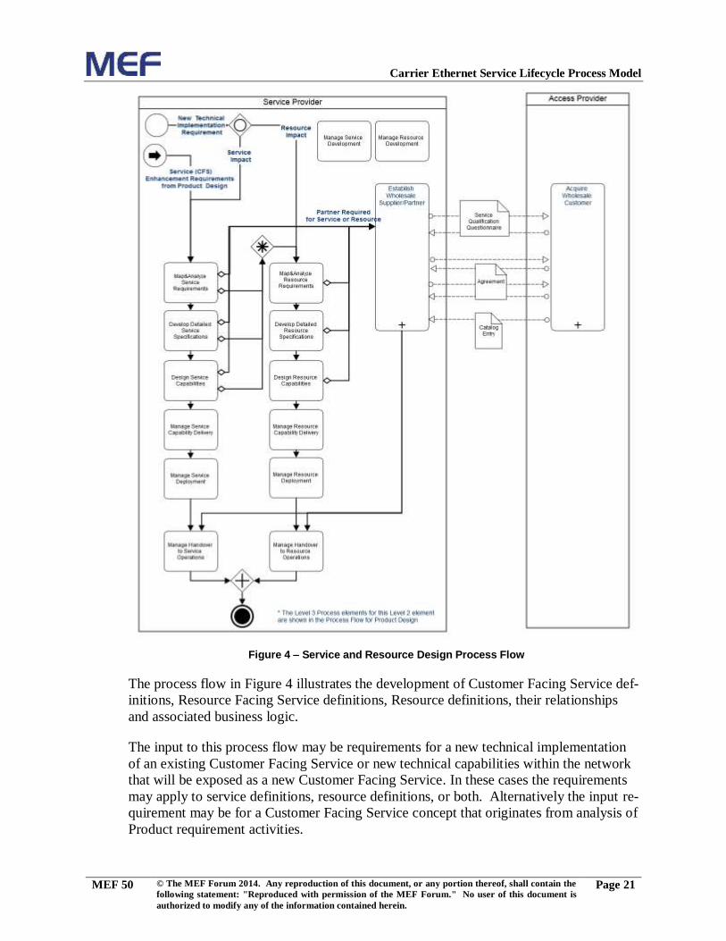
Page 21
Figure 4 – Service and Resource Design Process Flow
The process flow in Figure 4 illustrates the development of Customer Facing Service def-
initions, Resource Facing Service definitions, Resource definitions, their relationships
and associated business logic.
The input to this process flow may be requirements for a new technical implementation
of an existing Customer Facing Service or new technical capabilities within the network
that will be exposed as a new Customer Facing Service. In these cases the requirements
may apply to service definitions, resource definitions, or both. Alternatively the input re-
quirement may be for a Customer Facing Service concept that originates from analysis of
Product requirement activities.
Page 26
Carrier Ethernet Service Lifecycle Process Model
MEF 50 © The MEF Forum 2014. Any reproduction of this document, or any portion thereof, shall contain the
following statement: "Reproduced with permission of the MEF Forum." No user of this document is
authorized to modify any of the information contained herein.
Page 22
The overall development of Service definitions is coordinated by “Manage Service De-
velopment”, which interacts appropriately with “Manage Product Development” and
“Manage Resource Development” to ensure the necessary synchronization of their re-
spective deliverables.
The development of Service definitions must first assess incoming requirements to deter-
mine whether new Service definitions must be created, whether existing Service defini-
tions must be modified, or both. Following this analysis step, the specification document
for the Service definition is developed or refined. The specification may include high-
level design logic and business or technical rules for selecting and configuring appropri-
ate Resource Facing Services and/or Resources; process decision, approval and measure-
ment points; and dependencies on other Service capabilities from within the Service Pro-
vider’s infrastructure. The Service capabilities may have further dependences on capabil-
ities represented by Resource Facing Services or Resources.
During any of these activities, incremental Resource requirements may be identified,
which are dealt with through a sequence of activities that deal with Resource definitions.
The inputs to this sequence are the requirements originating from analysis of service re-
quirements or direct requirements for a new technical implementation. The overall devel-
opment of Resource and Resource Facing Service Definitions is coordinated by “Manage
Resource Development”, which interacts appropriately with “Manage Service Develop-
ment” and “Manage Product Development” to ensure the necessary synchronization of
their respective deliverables.
The development of Resource definitions starts with the assessment of the requirements
to determine whether new Resource definitions must be created, or whether existing ones
must be modified, or both. Following this analysis step, the specification document for
the Resource definition is created or updated. The specification may include overall de-
sign logic implementing business and technical rules on Resource selection and configu-
ration, and dependencies on Resource capabilities from within the Service Provider’s in-
frastructure.
Although not explicitly shown in the process flow, it is possible that analysis, specifica-
tion and design activities for resources may also identify additional service requirements.
As a result of analyzing Service or Resource requirements, developing specifications or
design, it may be determined that a new capability from a wholesale partner is required.
In this case it may be necessary to select an appropriate wholesale supplier and onboard a
product offering from them. In the Service Provider’s environment, the wholesale prod-
uct offering may be exposed as a service or a resource.
The interactions for establishing a supplier/partner relationship between Service Provider
and Access Providers is detailed later in this document in Figure 5 – Establish
Relationship between Service Provider and Access Provider.
Once Resource capabilities have been specified and designed, they are tested and deliv-
ered according to the Service Provider’s standard development processes. Following this,
Page 27
Carrier Ethernet Service Lifecycle Process Model
MEF 50 © The MEF Forum 2014. Any reproduction of this document, or any portion thereof, shall contain the
following statement: "Reproduced with permission of the MEF Forum." No user of this document is
authorized to modify any of the information contained herein.
Page 23
the delivered capabilities are deployed and accepted into the Service Provider’s produc-
tion environments, including where necessary, the network. This acceptance may involve
trials and Proofs of Concept to ensure that the Resource is operating as expected from
both technical and commercial perspectives. The final step in this process is the Hando-
ver to Resource Operations that enables the Resource definition to be used for Service
Fulfillment and Service Assurance.
Similarly, the service is tested and delivered according to the Service Provider’s standard
development processes, then deployed and accepted into the Service Provider’s produc-
tion environments. The final step in this process is the Handover to Service Operations
while enables the Service Definition to be used for Service Fulfillment.
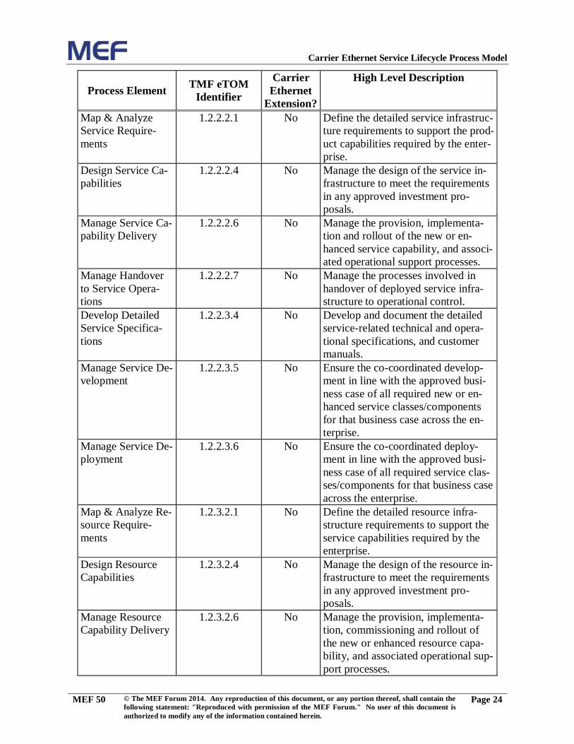
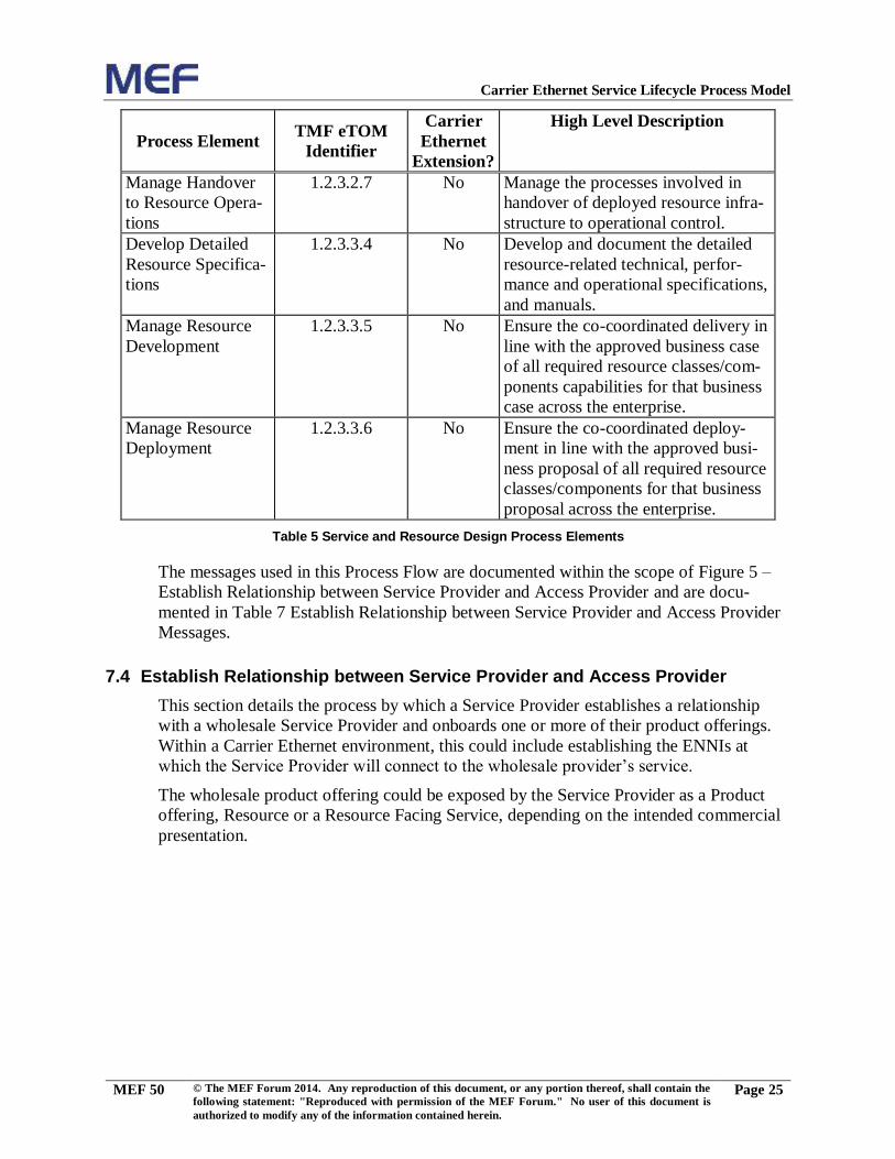
Table 5 introduces the Process Elements used in the Process Flow and identifies those
that are defined in [1] by listing the TMF eTOM Process Identifier. If a Process Element
has not been defined within eTOM, the level is listed as N/A and the Process Element
name in the Process Flow is shown in italic font.
Page 28
Carrier Ethernet Service Lifecycle Process Model
MEF 50 © The MEF Forum 2014. Any reproduction of this document, or any portion thereof, shall contain the
following statement: "Reproduced with permission of the MEF Forum." No user of this document is
authorized to modify any of the information contained herein.
Page 24
Process Element TMF eTOM
Identifier
Carrier
Ethernet
Extension?
High Level Description
Map & Analyze
Service Require-
ments
1.2.2.2.1
No Define the detailed service infrastruc-
ture requirements to support the prod-
uct capabilities required by the enter-
prise.
Design Service Ca-
pabilities
1.2.2.2.4
No Manage the design of the service in-
frastructure to meet the requirements
in any approved investment pro-
posals.
Manage Service Ca-
pability Delivery
1.2.2.2.6
No Manage the provision, implementa-
tion and rollout of the new or en-
hanced service capability, and associ-
ated operational support processes.
Manage Handover
to Service Opera-
tions
1.2.2.2.7
No Manage the processes involved in
handover of deployed service infra-
structure to operational control.
Develop Detailed
Service Specifica-
tions
1.2.2.3.4
No Develop and document the detailed
service-related technical and opera-
tional specifications, and customer
manuals.
Manage Service De-
velopment
1.2.2.3.5
No Ensure the co-coordinated develop-
ment in line with the approved busi-
ness case of all required new or en-
hanced service classes/components
for that business case across the en-
terprise.
Manage Service De-
ployment
1.2.2.3.6
No Ensure the co-coordinated deploy-
ment in line with the approved busi-
ness case of all required service clas-
ses/components for that business case
across the enterprise.
Map & Analyze Re-
source Require-
ments
1.2.3.2.1
No Define the detailed resource infra-
structure requirements to support the
service capabilities required by the
enterprise.
Design Resource
Capabilities
1.2.3.2.4
No Manage the design of the resource in-
frastructure to meet the requirements
in any approved investment pro-
posals.
Manage Resource
Capability Delivery
1.2.3.2.6
No Manage the provision, implementa-
tion, commissioning and rollout of
the new or enhanced resource capa-
bility, and associated operational sup-
port processes.
Page 29
Carrier Ethernet Service Lifecycle Process Model
MEF 50 © The MEF Forum 2014. Any reproduction of this document, or any portion thereof, shall contain the
following statement: "Reproduced with permission of the MEF Forum." No user of this document is
authorized to modify any of the information contained herein.
Page 25
Process Element TMF eTOM
Identifier
Carrier
Ethernet
Extension?
High Level Description
Manage Handover
to Resource Opera-
tions
1.2.3.2.7
No Manage the processes involved in
handover of deployed resource infra-
structure to operational control.
Develop Detailed
Resource Specifica-
tions
1.2.3.3.4
No Develop and document the detailed
resource-related technical, perfor-
mance and operational specifications,
and manuals.
Manage Resource
Development
1.2.3.3.5
No Ensure the co-coordinated delivery in
line with the approved business case
of all required resource classes/com-
ponents capabilities for that business
case across the enterprise.
Manage Resource
Deployment
1.2.3.3.6
No Ensure the co-coordinated deploy-
ment in line with the approved busi-
ness proposal of all required resource
classes/components for that business
proposal across the enterprise.
Table 5 Service and Resource Design Process Elements
The messages used in this Process Flow are documented within the scope of Figure 5 –
Establish Relationship between Service Provider and Access Provider and are docu-
mented in Table 7 Establish Relationship between Service Provider and Access Provider
Messages.
7.4 Establish Relationship between Service Provider and Access Provider
This section details the process by which a Service Provider establishes a relationship
with a wholesale Service Provider and onboards one or more of their product offerings.
Within a Carrier Ethernet environment, this could include establishing the ENNIs at
which the Service Provider will connect to the wholesale provider’s service.
The wholesale product offering could be exposed by the Service Provider as a Product
offering, Resource or a Resource Facing Service, depending on the intended commercial
presentation.
Page 30
Carrier Ethernet Service Lifecycle Process Model
MEF 50 © The MEF Forum 2014. Any reproduction of this document, or any portion thereof, shall contain the
following statement: "Reproduced with permission of the MEF Forum." No user of this document is
authorized to modify any of the information contained herein.
Page 26
Figure 5 – Establish Relationship between Service Provider and Access Provider
Page 31
Carrier Ethernet Service Lifecycle Process Model
MEF 50 © The MEF Forum 2014. Any reproduction of this document, or any portion thereof, shall contain the
following statement: "Reproduced with permission of the MEF Forum." No user of this document is
authorized to modify any of the information contained herein.
Page 27
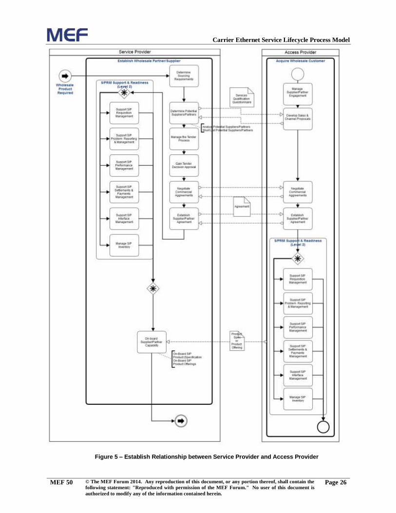
The process flow in Figure 5 introduces the activities involved in establishing a new sup-
plier/partner relationship and making the wholesale partner’s product offering available
for use in the Service Provider’s environment.
Note that the reference processes are drawn from the Supplier/Partner Domain of TMF’s
Business Process Framework processes and not the more recently introduced Engaged
Party Domain.
As a result of analyzing Product, Service or Resource requirements, developing specifica-
tions or design, it may be determined that a wholesale partner is required. In this case the
Sourcing requirements would be established and a set of potential suppliers established
by analyzing their responses to MEF's Service Qualification Questionnaire.
Once a short list of potential suppliers is established a formal tender procedure may be
followed resulting in the selection of one or more suppliers with commercial/technical
agreements in place. For a new supplier/partner, such agreements must establish the inter-
working in areas such as Requisition management (i.e. order handling), Problem Report-
ing, Performance Management, Payment management, overall procedures for interacting
with the supplier, and appropriate visibility of the supplier’s Product inventory.
Once such interworking is in place, the wholesale product offering can be onboarded to
the Service Provider’s environment.
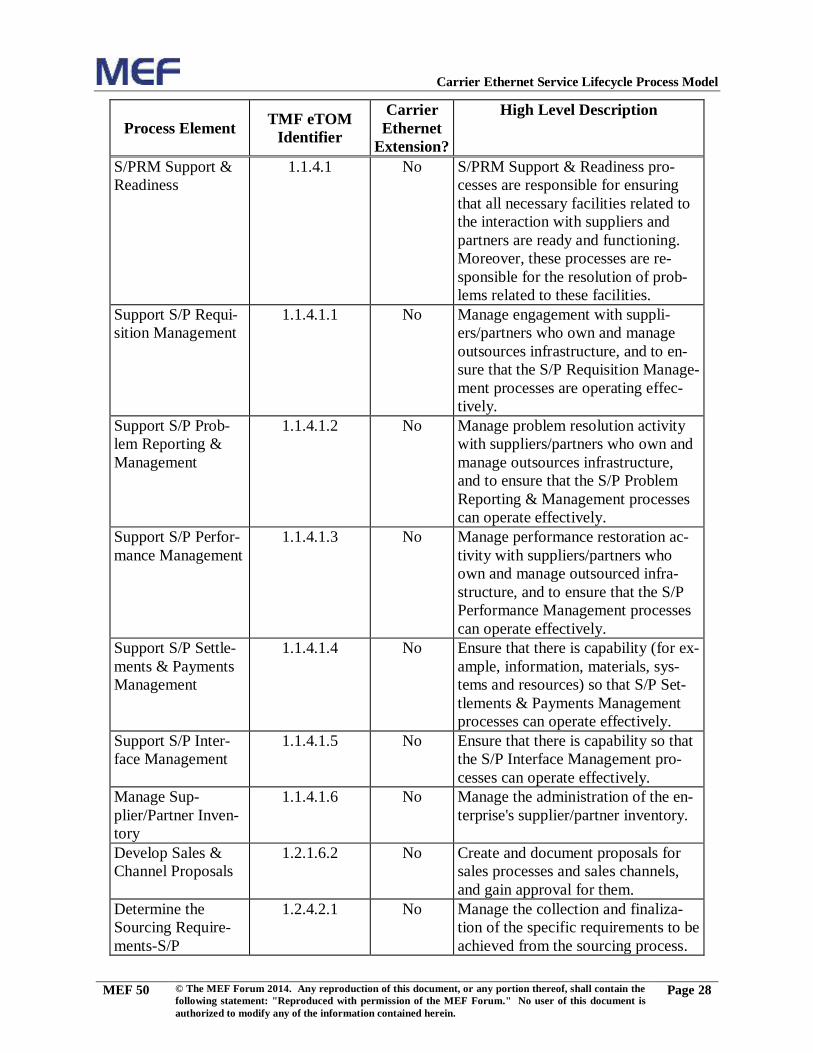
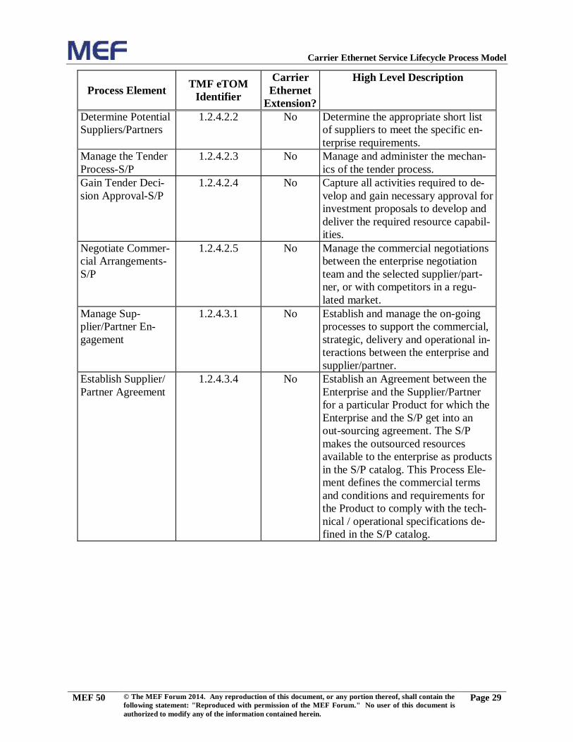
Table 6 introduces the Process Elements used in the Process Flow and identifies those
that are defined in [1] by listing the TMF eTOM Process Identifier. If a Process Element
has not been defined within eTOM, the level is listed as N/A and the Process Element
name in the Process Flow is shown in italic font.
Page 32
Carrier Ethernet Service Lifecycle Process Model
MEF 50 © The MEF Forum 2014. Any reproduction of this document, or any portion thereof, shall contain the
following statement: "Reproduced with permission of the MEF Forum." No user of this document is
authorized to modify any of the information contained herein.
Page 28
Process Element TMF eTOM
Identifier
Carrier
Ethernet
Extension?
High Level Description
S/PRM Support &
Readiness
1.1.4.1 No S/PRM Support & Readiness pro-
cesses are responsible for ensuring
that all necessary facilities related to
the interaction with suppliers and
partners are ready and functioning.
Moreover, these processes are re-
sponsible for the resolution of prob-
lems related to these facilities.
Support S/P Requi-
sition Management
1.1.4.1.1
No Manage engagement with suppli-
ers/partners who own and manage
outsources infrastructure, and to en-
sure that the S/P Requisition Manage-
ment processes are operating effec-
tively.
Support S/P Prob-
lem Reporting &
Management
1.1.4.1.2
No Manage problem resolution activity
with suppliers/partners who own and
manage outsources infrastructure,
and to ensure that the S/P Problem
Reporting & Management processes
can operate effectively.
Support S/P Perfor-
mance Management
1.1.4.1.3
No Manage performance restoration ac-
tivity with suppliers/partners who
own and manage outsourced infra-
structure, and to ensure that the S/P
Performance Management processes
can operate effectively.
Support S/P Settle-
ments & Payments
Management
1.1.4.1.4
No Ensure that there is capability (for ex-
ample, information, materials, sys-
tems and resources) so that S/P Set-
tlements & Payments Management
processes can operate effectively.
Support S/P Inter-
face Management
1.1.4.1.5
No Ensure that there is capability so that
the S/P Interface Management pro-
cesses can operate effectively.
Manage Sup-
plier/Partner Inven-
tory
1.1.4.1.6
No Manage the administration of the en-
terprise's supplier/partner inventory.
Develop Sales &
Channel Proposals
1.2.1.6.2 No Create and document proposals for
sales processes and sales channels,
and gain approval for them.
Determine the
Sourcing Require-
ments-S/P
1.2.4.2.1
No Manage the collection and finaliza-
tion of the specific requirements to be
achieved from the sourcing process.
Page 33
Carrier Ethernet Service Lifecycle Process Model
MEF 50 © The MEF Forum 2014. Any reproduction of this document, or any portion thereof, shall contain the
following statement: "Reproduced with permission of the MEF Forum." No user of this document is
authorized to modify any of the information contained herein.
Page 29
Process Element TMF eTOM
Identifier
Carrier
Ethernet
Extension?
High Level Description
Determine Potential
Suppliers/Partners
1.2.4.2.2
No Determine the appropriate short list
of suppliers to meet the specific en-
terprise requirements.
Manage the Tender
Process-S/P
1.2.4.2.3
No Manage and administer the mechan-
ics of the tender process.
Gain Tender Deci-
sion Approval-S/P
1.2.4.2.4
No Capture all activities required to de-
velop and gain necessary approval for
investment proposals to develop and
deliver the required resource capabil-
ities.
Negotiate Commer-
cial Arrangements-
S/P
1.2.4.2.5
No Manage the commercial negotiations
between the enterprise negotiation
team and the selected supplier/part-
ner, or with competitors in a regu-
lated market.
Manage Sup-
plier/Partner En-
gagement
1.2.4.3.1
No Establish and manage the on-going
processes to support the commercial,
strategic, delivery and operational in-
teractions between the enterprise and
supplier/partner.
Establish Supplier/
Partner Agreement
1.2.4.3.4
No Establish an Agreement between the
Enterprise and the Supplier/Partner
for a particular Product for which the
Enterprise and the S/P get into an
out-sourcing agreement. The S/P
makes the outsourced resources
available to the enterprise as products
in the S/P catalog. This Process Ele-
ment defines the commercial terms
and conditions and requirements for
the Product to comply with the tech-
nical / operational specifications de-
fined in the S/P catalog.
Page 34
Carrier Ethernet Service Lifecycle Process Model
MEF 50 © The MEF Forum 2014. Any reproduction of this document, or any portion thereof, shall contain the
following statement: "Reproduced with permission of the MEF Forum." No user of this document is
authorized to modify any of the information contained herein.
Page 30
Process Element TMF eTOM
Identifier
Carrier
Ethernet
Extension?
High Level Description
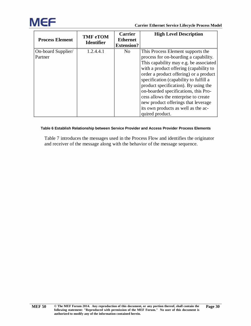
On-board Supplier/
Partner
1.2.4.4.1
No This Process Element supports the
process for on-boarding a capability.
This capability may e.g. be associated
with a product offering (capability to
order a product offering) or a product
specification (capability to fulfill a
product specification). By using the
on-boarded specifications, this Pro-
cess allows the enterprise to create
new product offerings that leverage
its own products as well as the ac-
quired product.
Table 6 Establish Relationship between Service Provider and Access Provider Process Elements
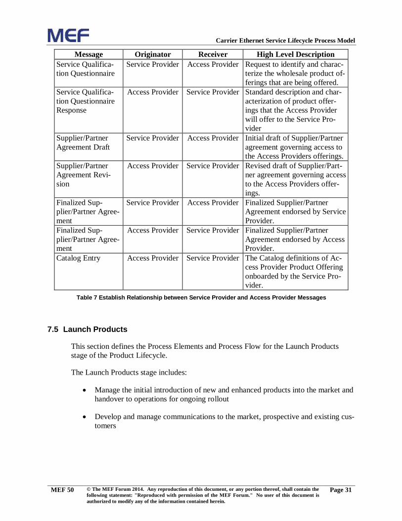
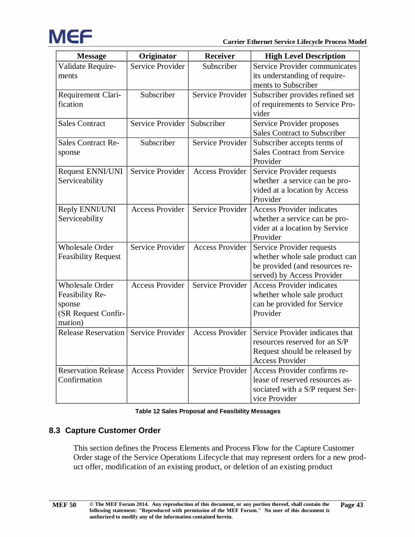
Table 7 introduces the messages used in the Process Flow and identifies the originator
and receiver of the message along with the behavior of the message sequence.
Page 35
Carrier Ethernet Service Lifecycle Process Model
MEF 50 © The MEF Forum 2014. Any reproduction of this document, or any portion thereof, shall contain the
following statement: "Reproduced with permission of the MEF Forum." No user of this document is
authorized to modify any of the information contained herein.
Page 31
Message Originator Receiver High Level Description
Service Qualifica-
tion Questionnaire
Service Provider Access Provider Request to identify and charac-
terize the wholesale product of-
ferings that are being offered.
Service Qualifica-
tion Questionnaire
Response
Access Provider Service Provider Standard description and char-
acterization of product offer-
ings that the Access Provider
will offer to the Service Pro-
vider
Supplier/Partner
Agreement Draft
Service Provider Access Provider Initial draft of Supplier/Partner
agreement governing access to
the Access Providers offerings.
Supplier/Partner
Agreement Revi-
sion
Access Provider Service Provider Revised draft of Supplier/Part-
ner agreement governing access
to the Access Providers offer-
ings.
Finalized Sup-
plier/Partner Agree-
ment
Service Provider Access Provider Finalized Supplier/Partner
Agreement endorsed by Service
Provider.
Finalized Sup-
plier/Partner Agree-
ment
Access Provider Service Provider Finalized Supplier/Partner
Agreement endorsed by Access
Provider.
Catalog Entry Access Provider Service Provider The Catalog definitions of Ac-
cess Provider Product Offering
onboarded by the Service Pro-
vider.
Table 7 Establish Relationship between Service Provider and Access Provider Messages
7.5 Launch Products
This section defines the Process Elements and Process Flow for the Launch Products
stage of the Product Lifecycle.
The Launch Products stage includes:
Manage the initial introduction of new and enhanced products into the market and
handover to operations for ongoing rollout
Develop and manage communications to the market, prospective and existing cus-
tomers
Page 36
Carrier Ethernet Service Lifecycle Process Model
MEF 50 © The MEF Forum 2014. Any reproduction of this document, or any portion thereof, shall contain the
following statement: "Reproduced with permission of the MEF Forum." No user of this document is
authorized to modify any of the information contained herein.
Page 32
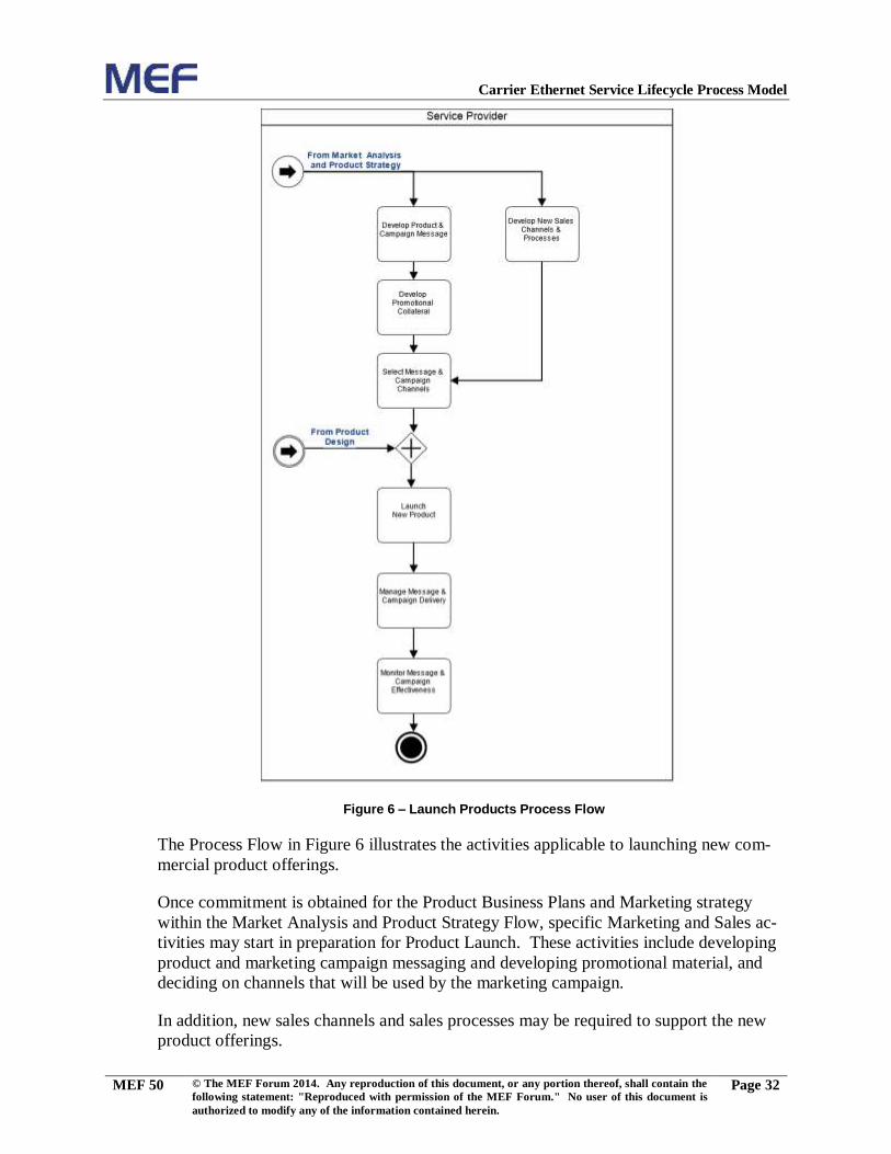
Figure 6 – Launch Products Process Flow
The Process Flow in Figure 6 illustrates the activities applicable to launching new com-
mercial product offerings.
Once commitment is obtained for the Product Business Plans and Marketing strategy
within the Market Analysis and Product Strategy Flow, specific Marketing and Sales ac-
tivities may start in preparation for Product Launch. These activities include developing
product and marketing campaign messaging and developing promotional material, and
deciding on channels that will be used by the marketing campaign.
In addition, new sales channels and sales processes may be required to support the new
product offerings.
Page 37
Carrier Ethernet Service Lifecycle Process Model
MEF 50 © The MEF Forum 2014. Any reproduction of this document, or any portion thereof, shall contain the
following statement: "Reproduced with permission of the MEF Forum." No user of this document is
authorized to modify any of the information contained herein.
Page 33
When the marketing and sale preparation is complete along with the deployment of the
necessary service and resource capabilities to support fulfillment of orders, the new prod-
uct offerings will be launched to the market.
As part of the Product Launch, the Marketing campaign and messaging will be delivered
to the market, and on an ongoing basis monitored for effectiveness.
Table 8 introduces the Process Elements used in the Process Flow and identifies those
that are defined in [1] by listing the TMF eTOM Process Identifier. If a Process Element
has not been defined within eTOM, the level is listed as N/A and the Process Element
name in the Process Flow is shown in italic font.
Process Element TMF eTOM
Identifier
Carrier
Ethernet
Extension?
High Level Description
Launch New Prod-
ucts
1.2.1.5.7
No Manage the initial introduction of
new and enhanced products into the
market and handover to operations
for ongoing rollout.
Develop New Sales
Channels & Pro-
cesses
1.2.1.6.2
No Develop New Sales Channels & Pro-
cesses.
Develop Product &
Campaign Message
1.2.1.7.2
No Manage all activities and stakeholder
engagement to develop and agree the
specific campaign or promotion mes-
sage.
Select Message &
Campaign Channels
1.2.1.7.3
No Manage the selection of the appropri-
ate channel or channels to support the
message delivery and/or campaign.
Develop Promo-
tional Collateral
1.2.1.7.4
No Ensure that all associated collateral is
produced to support the market mes-
sage and /or campaign.
Manage Message &
Campaign Delivery
1.2.1.7.5
No Manage and co-ordinate the delivery
of the messages and campaigns into
the selected channels.
Monitor Message &
Campaign Effec-
tiveness
1.2.1.7.6
No Establish metrics and monitoring and
reporting processes to gauge the ef-
fectiveness of market messages and
product promotional campaigns.
Table 8 Launch Products Process Elements
8. Service Operations Lifecycle Management
This section defines the process models for the stages of Service Operations Lifecycle
management. For each Process Flow there are at least three entities (e.g., stakeholders or
actors) involved in the flow: 1) Subscriber, 2) Service Provider, and 3) Access Provider
Page 38
Carrier Ethernet Service Lifecycle Process Model
MEF 50 © The MEF Forum 2014. Any reproduction of this document, or any portion thereof, shall contain the
following statement: "Reproduced with permission of the MEF Forum." No user of this document is
authorized to modify any of the information contained herein.
Page 34
(one or more). Each entity is represented by a BPMN “Pool”. The Process Elements and
interactions of these elements (Process Flows) are focused on the Service Provider where
“Messages” are sent towards the Subscriber and Access Provider. It is important to rec-
ognize that the Access Provider Pool represents another Service Provider acting in the
role of providing a wholesale service. Therefore the Processes within the Access Pro-
vider Pool are also directly applicable to Service Providers, and vice versa. On the other
hand, the Subscriber Pool is presented as a black box since only the interfaces between
the Service Provider and Subscriber are of interest in this case.
Furthermore it should be noted that an Access Provider itself may also rely on wholesale
services provided by other Access Providers. This multi-tier relationship has not been
explicitly shown, but can be viewed as the Access Provider interacting with another Ac-
cess Provider from the perspective of the Service Provider Pool.
8.1 Marketing Fulfillment Response
This section defines the Process Elements and Process Flow for the Marketing Fulfill-
ment Response stage of the Service Operations Lifecycle.
Figure 7 – Marketing Fulfillment Response Process Flow
Page 39
Carrier Ethernet Service Lifecycle Process Model
MEF 50 © The MEF Forum 2014. Any reproduction of this document, or any portion thereof, shall contain the
following statement: "Reproduced with permission of the MEF Forum." No user of this document is
authorized to modify any of the information contained herein.
Page 35
The Process Flow in Figure 7 illustrates the activities applicable to managing sales oppor-
tunities arising through marketing Carrier Ethernet based products to new and existing
Subscribers, up-selling existing Subscribers and direct Subscriber requests.
As a result of a marketing campaign for Carrier Ethernet based product offers, potential
Subscribers may express interest in products being offered by the Service Provider. This
may be expressed informally or through a formal Request for Proposal (RFP). These
leads are collected and passed onto sales activities. Within the “Manage Prospects” ac-
tivity these incoming leads are incorporated into the sales “pipeline”, applicable products
are identified and the prospects are assigned to an appropriate sales channel.
If the prospect is not an existing Subscriber, the “Establish Customer Relationship” Pro-
cess Element is applicable. In this Process Element the Subscriber details are validated, it
is verified that this Subscriber is not already known to the Service Provider’s systems, a
unique identifier is assigned, account credentials established and additional relevant Sub-
scriber information is collected. It should be noted that further information may be gath-
ered from the Subscriber in later activities within this or other flows.
The incoming request originating from the marketing lead, from a direct Subscriber re-
quest, or from an up-sell is managed within “Customer Interface Management”, which
then passes the request on to the “Qualify Opportunity” Process Element. Up-sell oppor-
tunities arise from ongoing interactions with the Subscriber described within the “Man-
age Sales Account” Process Element. As a result of understanding the Subscriber spe-
cific requirements, recommendations for appropriate offerings may be made to the Sub-
scriber that results in new incoming requests.
The “Qualify Opportunity” Process Element ensures that a decision to proceed with the
opportunity is based on an appropriate assessment of risk, effort, ability to meet Sub-
scriber expectations, strategic importance and profit potential. If the opportunity is quali-
fied, the opportunity is passed on to the Quote management process flow shown in Figure
8, otherwise the Subscriber is notified that the Service Provider will not be providing a
response to their request.
All sales prospects, sales, channel management and commissions are managed within a
sale inventory. “Manage Sales Inventory” is not shown directly within the process flow
itself, but sales inventory may be updated as a result of any of the activities within the
flow illustrated here.
Table 9 introduces the Process Elements used in the Process Flow and identifies those
that are defined in [1] by listing the TMF eTOM Process Identifier. If a Process Element
has not been defined within eTOM, the level is listed as N/A and the Process Element
name in the Process Flow is shown in italic font.
Page 40
Carrier Ethernet Service Lifecycle Process Model
MEF 50 © The MEF Forum 2014. Any reproduction of this document, or any portion thereof, shall contain the
following statement: "Reproduced with permission of the MEF Forum." No user of this document is
authorized to modify any of the information contained herein.
Page 36
Process Element TMF eTOM
Identifier
Carrier
Ethernet
Extension?
High Level Description
Track Leads 1.1.1.3.2 No Track leads generated through mar-
keting, or that arise in the course of
business
Manage Prospect 1.1.1.4.1 No Match assigned leads with the most
appropriate products and ensure that
these prospects are handled appropri-
ately
Qualify Opportunity 1.1.1.4.2 No Ensure that the opportunity is quali-
fied in terms of any associated risk
and the amount of effort required to
achieve a sale
Cross/Up Selling 1.1.1.4.5 No Ensure that the value of the relation-
ship between the customer and Ser-
vice Provider is maximized by selling
additional, or more of the existing,
products.
Manage Sales Ac-
counts
1.1.1.4.7 No Manage the sales accounts assigned
to the sales channel on a day-day ba-
sis
Establish Customer
Relationship
1.1.1.16.2 No Verify the customer identity and
manage the customer identity across
the Enterprise.
Notify Customer 1.1.1.18.5 No Notify the customer when interesting
events happen.
Customer Interface
Management
1.1.1.18.9 No Managing all interfaces between the
enterprise and potential and existing
customers.
Manage Sales In-
ventory
1.1.1.20.12 No Establish, manage and administer the
enterprise's inventory of sales pro-
spects, actual sales, channel manage-
ment and sales commissions, as em-
bodied in the Sales Inventory Data-
base, and monitor and report on the
usage and access to the sales inven-
tory, and the quality of the data main-
tained in it.
Table 9 Marketing Fulfillment Response Process Elements
Table 10 introduces the messages used in the Process Flow and identifies the originator
and receiver of the message along with the behavior of the message sequence.
Page 41
Carrier Ethernet Service Lifecycle Process Model
MEF 50 © The MEF Forum 2014. Any reproduction of this document, or any portion thereof, shall contain the
following statement: "Reproduced with permission of the MEF Forum." No user of this document is
authorized to modify any of the information contained herein.
Page 37
Message Originator Receiver High Level Description
Product Interest Subscriber Service Provider Subscriber indicates product in-
terest to Service Provider
though a formal request such as
an RFP, or an informal request.
Verify Customer-
Request Customer
Data
Service Provider Subscriber Service Provider requests cus-
tomer details from Subscriber
Acquire Customer
Data
Subscriber Service Provider Subscriber provides infor-
mation identifying themselves
to the Service Provider.
Recommendations Service Provider Subscriber Service Provider suggests a set
of Product Offerings to the
Subscriber
Customer Request Subscriber Service Provider Customer requests product of-
ferings from the Service Pro-
vider
Customer Notifica-
tion that Quote will
not be provided
Service Provider Subscriber Service Provider provides noti-
fication that sales proposal will
not be provided to Subscriber.
Table 10 Marketing Fulfillment Response Messages
8.2 Sales Proposal and Feasibility
This section defines the Process Elements and Process Flow for the Sales Proposal and
Feasibility stage of the Service Operations Lifecycle.
Page 42
Carrier Ethernet Service Lifecycle Process Model
MEF 50 © The MEF Forum 2014. Any reproduction of this document, or any portion thereof, shall contain the
following statement: "Reproduced with permission of the MEF Forum." No user of this document is
authorized to modify any of the information contained herein.
Page 38
Figure 8 – Sales Proposal & Feasibility Process Flow
The Process Flow in Figure 8 illustrates the activities applicable to developing sales pro-
posals (quotes) in response to qualified sales opportunities.
As an initial operation within the development of a sales proposal, the Service Provide
may interact with the Subscriber to validate their requirements. As a result of feedback
and questions from the Service Provider, a refined set of requirements may be provided
by the (potential) Subscriber.
As part of the “Development Sales Proposal” Process Element, the Service Provider may
recognize that it does not have suitable product offerings, products or services to support
Page 43
Carrier Ethernet Service Lifecycle Process Model
MEF 50 © The MEF Forum 2014. Any reproduction of this document, or any portion thereof, shall contain the
following statement: "Reproduced with permission of the MEF Forum." No user of this document is
authorized to modify any of the information contained herein.
Page 39
the request. If the opportunity is sufficient, this may result in the development (or
onboarding) of new product offerings, products and services. These activities, which
may vary greatly in complexity, effort and timeframe, are not detailed in this process
flow, but would occur in the context of general Product Lifecycle flows.
A sales proposal may include product offerings based on E-Access Services products
sourced from external suppliers in addition to the Carrier Ethernet-based products offered
directly by the Service Provider. In such cases, the availability of such product offers for
a specific location or with specific parameters may be verified by issuing a Serviceability
Request to the Access Provider. The Access Provider evaluates this request by perform-
ing some subset of determining the feasibility of an order with the specified location and
parameters. These activities are represented by the “Qualify Opportunity” Process Ele-
ment in which the Access Provider assesses risk and effort, as well as by the “Determine
Customer Order Feasibility” Process Element in which the Access Provider determines
whether the request can be met from a technical perspective. The result of this Servicea-
bility assessment is returned to the Service Provider.
For Products supported directly by the Service Provider, “Customer Order Feasibility”
will be determined. This check may take many forms and involve CRM logic, internal
serviceability data and possibly service design. In some cases, a Subscriber commitment
may require resources to be reserved to ensure that the customer order will be fulfilled
with a high degree of certainty. In such cases, installation appointments may be sched-
uled, service identifiers allocated, resources allocated and products offered by Access
Providers reserved using a wholesale order feasibility request with reservations.
Such a request incoming to the Access Provider requires that the Access provider reserve
resources as a result of “Determining Customer Order Feasibility”. This sequence is the
same as that identified in the Service Provider process, and may result in a request cas-
cading to yet another wholesale provider (although this is not explicitly shown in the dia-
gram).
When the reservations are complete, the Access Provider responds to the Service Pro-
vider with a Wholesale Order Feasibility response which includes confirmation that the
reservation has been made. In an ATIS Access Service Request context, the response
would take the form of the “Firm Order Confirmation”.
Within the Service Provider flow, if the Sales proposal is determined not to be feasible,
the sales proposal may be refined until a feasible proposal is achieved. At this point, a
credit check of the Subscriber is performed prior to negotiation of the Sale Contract.
The “Negotiate Sales Contract” Process Element might require further refinement of the
Sale Proposal. Once an acceptable Sales Contract is established the Subscriber will sign
the contract and the overall flow will progress to the stage of capturing the customer or-
der.
If a Sales contract cannot be successfully negotiated, and if reservations have been made,
these reservations are cancelled. This includes cancelling work force management ap-
Page 44
Carrier Ethernet Service Lifecycle Process Model
MEF 50 © The MEF Forum 2014. Any reproduction of this document, or any portion thereof, shall contain the
following statement: "Reproduced with permission of the MEF Forum." No user of this document is
authorized to modify any of the information contained herein.
Page 40
pointments, recovering service and resource instances and requesting that the Access Pro-
vider release any reserved resources. The Access Provider follows a similar process for
releasing reservations and responds to the Service Provider when this is complete.
Table 11 introduces the Process Elements used in the Process Flow and identifies those
that are defined in [1] by listing the TMF eTOM Process Identifier. If a Process Element
has not been defined within eTOM, the level is listed as N/A and the Process Element
name in the Process Flow is shown is italic font.
Page 45
Carrier Ethernet Service Lifecycle Process Model
MEF 50 © The MEF Forum 2014. Any reproduction of this document, or any portion thereof, shall contain the
following statement: "Reproduced with permission of the MEF Forum." No user of this document is
authorized to modify any of the information contained herein.
Page 41
Process Element TMF eTOM
Identifier
Carrier
Ethernet
Extension?
High Level Description
Qualify Opportunity 1.1.1.4.2 No Ensure that the opportunity is quali-
fied in terms of any associated risk
and the amount of effort required to
achieve a sale
Negotiate
Sales/Contract
1.1.1.4.3 No Close the sale with terms that are un-
derstood by the customer, and are mu-
tually agreeable to both the customer
and the Service Provider.
Develop Sales Pro-
posal
1.1.1.4.6 No Develop a sales proposal to respond to
the customer’s requirements
Determine Customer
Order Feasibility
1.1.1.5.1 Yes Check the availability and/or the fea-
sibility of providing and supporting
standard and customized product of-
ferings where specified to a customer.
Authorize Credit 1.1.1.5.2 No Assess a customer's credit worthiness
in support of managing customer risk
and company exposure to bad debt
Manage Sales In-
ventory
1.1.1.20.12
No Establish, manage and administer the
enterprise's inventory of sales pro-
spects, actual sales, channel manage-
ment and sales commissions, as em-
bodied in the Sales Inventory Data-
base, and monitor and report on the
usage and access to the sales inven-
tory, and the quality of the data main-
tained in it.
Allocate Specific
Service Parameters
to Services
1.1.2.2.2 No Issue service identifiers for new ser-
vices.
Recover Service 1.1.2.2.10 No Recover specific services that are no
longer required by customers.
Allocate & Install
Resources
1.1.3.2.1 No Allocate specific resources required to
support a specific service
Recover Resource 1.1.3.2.9 No Recover specific resources that are no
longer required.
Manage Schedules
& Appointments
1.1.3.7.1 No Manages the appointment schedule of
assignable staff.
Determine S/P Pre-
Requisition Feasibil-
ity
1.1.4.2.2 No Determine the ability of suppli-
ers/partners to deliver the specific re-
sources, services or products, within
the specified requirements
Page 46
Carrier Ethernet Service Lifecycle Process Model
MEF 50 © The MEF Forum 2014. Any reproduction of this document, or any portion thereof, shall contain the
following statement: "Reproduced with permission of the MEF Forum." No user of this document is
authorized to modify any of the information contained herein.
Page 42
Process Element TMF eTOM
Identifier
Carrier
Ethernet
Extension?
High Level Description
Track & Manage
S/P Requisition
1.1.4.2.3 No Ensure S/P requisition orders are be-
ing processed and delivered effi-
ciently and effectively
Manage S/P Re-
quests (Including
Self Service)
1.1.4.6.1
No Accept requests and enable the sup-
plier / partner to obtain the desired in-
formation from the enterprise, or iden-
tify and activate the appropriate pro-
cess area to accomplish the request
Mediate & Orches-
trate Supplier/Part-
ner Interactions
1.1.4.6.3 No Conversion of externally received
messages into the required internal
enterprise formats.
Table 11 Sales Proposal and Feasibility Process Elements
Currently a symmetric process definition from eTOM has not been identified by which an
Access Provider would respond to “Determine S/P Pre-Requisition Feasibility”. In the
diagrams above, “Determine Customer Order Feasibility” serves this purpose, even
though a Serviceability Request is not necessarily order based.
Table 12 introduces the messages used in the Process Flow and identifies the originator
and receiver of the message along with the behavior of the message sequence.
Page 47
Carrier Ethernet Service Lifecycle Process Model
MEF 50 © The MEF Forum 2014. Any reproduction of this document, or any portion thereof, shall contain the
following statement: "Reproduced with permission of the MEF Forum." No user of this document is
authorized to modify any of the information contained herein.
Page 43
Message Originator Receiver High Level Description
Validate Require-
ments
Service Provider Subscriber Service Provider communicates
its understanding of require-
ments to Subscriber
Requirement Clari-
fication
Subscriber Service Provider Subscriber provides refined set
of requirements to Service Pro-
vider
Sales Contract Service Provider Subscriber Service Provider proposes
Sales Contract to Subscriber
Sales Contract Re-
sponse
Subscriber Service Provider Subscriber accepts terms of
Sales Contract from Service
Provider
Request ENNI/UNI
Serviceability
Service Provider Access Provider Service Provider requests
whether a service can be pro-
vided at a location by Access
Provider
Reply ENNI/UNI
Serviceability
Access Provider Service Provider Access Provider indicates
whether a service can be pro-
vider at a location by Service
Provider
Wholesale Order
Feasibility Request
Service Provider Access Provider Service Provider requests
whether whole sale product can
be provided (and resources re-
served) by Access Provider
Wholesale Order
Feasibility Re-
sponse
(SR Request Confir-
mation)
Access Provider Service Provider Access Provider indicates
whether whole sale product
can be provided for Service
Provider
Release Reservation Service Provider Access Provider Service Provider indicates that
resources reserved for an S/P
Request should be released by
Access Provider
Reservation Release
Confirmation
Access Provider Service Provider Access Provider confirms re-
lease of reserved resources as-
sociated with a S/P request Ser-
vice Provider
Table 12 Sales Proposal and Feasibility Messages
8.3 Capture Customer Order
This section defines the Process Elements and Process Flow for the Capture Customer
Order stage of the Service Operations Lifecycle that may represent orders for a new prod-
uct offer, modification of an existing product, or deletion of an existing product
Page 48
Carrier Ethernet Service Lifecycle Process Model
MEF 50 © The MEF Forum 2014. Any reproduction of this document, or any portion thereof, shall contain the
following statement: "Reproduced with permission of the MEF Forum." No user of this document is
authorized to modify any of the information contained herein.
Page 44
Figure 9 – Capture Customer Order Process Flow
The Process Flow in
Figure 9 illustrates the activities applicable to capturing customer orders either from di-
rect Subscriber requests or from sales contracts that have been generated through the
Quote process. This flow reflects the interactions that occur with the Subscriber and Ac-
cess Providers.
A Subscriber may directly initiate contact with the Service Provider to purchase new
product offers or change their existing product offers. The “Customer Interface Manage-
ment” Process Element is responsible for managing all incoming requests from the Sub-
scriber. The request is expressed in terms of product offerings for which the feasibility of
delivering can be determined by using the same process sub-flow identified within the
Quote process. This may involve interactions with the Access Provider if wholesale E-
Access based services are required.
If the order is determined to be feasible, scheduling of the order is performed (usually
within CRM) and a customer order is issued. If the order is not feasible it is rejected and
the Subscriber notified.
Once the customer order is issued the overall process advances to Order Fulfillment.
Page 49
Carrier Ethernet Service Lifecycle Process Model
MEF 50 © The MEF Forum 2014. Any reproduction of this document, or any portion thereof, shall contain the
following statement: "Reproduced with permission of the MEF Forum." No user of this document is
authorized to modify any of the information contained herein.
Page 45
If it is determined that the Order is not feasible, the customer is notified and the process is
complete.
Table 13 introduces the Process Elements used in the Process Flow and identifies those
that are defined in [1] by listing the TMF eTOM Process Identifier. If a Process Element
has not been defined within eTOM, the level is listed as N/A and the Process Element
name in the Process Flow is shown is italic font.
Process Element TMF eTOM
Identifier
Carrier
Ethernet
Extension?
High Level Description
Issue Customer Or-
ders
1.1.1.5.6 No Issue correct and complete customer
orders
Customer Interface
Management
1.1.1.18.9 No Managing all interfaces between the
enterprise and potential and existing
customers.
Manage Appoint-
ment Schedule
1.1.3.7.1 No Manages the appointment schedule of
assignable staff.
Manage S/P Re-
quests (Including
Self Service)
1.1.4.6.1 No Accept requests and enable the sup-
plier / partner to obtain the desired in-
formation from the enterprise, or iden-
tify and activate the appropriate pro-
cess area to accomplish the request
Mediate & Orches-
trate Supplier/Part-
ner Interactions
1.1.4.6.3 No Ensure that transaction message struc-
ture and interactions conform to
agreed, externally defined standards
used by the enterprise and its suppli-
ers/partners
Table 13 Capture Customer Order Process Elements
Table 14 introduces the messages used in the Process Flow and identifies the originator
and receiver of the message along with the behavior of the message sequence.
Page 50
Carrier Ethernet Service Lifecycle Process Model
MEF 50 © The MEF Forum 2014. Any reproduction of this document, or any portion thereof, shall contain the
following statement: "Reproduced with permission of the MEF Forum." No user of this document is
authorized to modify any of the information contained herein.
Page 46
Message Originator Receiver High Level Description
Simple Request Subscriber Service Provider Subscriber requests Product Of-
ferings or changes to product
from Service Provider.
Order Rejected Service Provider Subscriber Service Provider notifies Sub-
scriber that Order cannot be ac-
cepted.
Wholesale Order
Feasibility Request
Service Provider Access Provider Service Provider requests
whether wholesale product can
be provided (and resources re-
served) by Access Provider
Wholesale Order
Feasibility Re-
sponse
(SR Request Confir-
mation)
Access Provider Service Provider Access Provider indicates
whether wholesale product can
be provided for Service Pro-
vider
Table 14 Capture Customer Order Messages
8.4 Service Configuration and Activation
This section defines the Process Elements and Process Flow for the Service Configura-
tion and Activation stage of the Service Operations Lifecycle.
Page 51
Carrier Ethernet Service Lifecycle Process Model
MEF 50 © The MEF Forum 2014. Any reproduction of this document, or any portion thereof, shall contain the
following statement: "Reproduced with permission of the MEF Forum." No user of this document is
authorized to modify any of the information contained herein.
Page 47
Figure 10 – Service Configuration and Activation Process Flow
Page 52
Carrier Ethernet Service Lifecycle Process Model
MEF 50 © The MEF Forum 2014. Any reproduction of this document, or any portion thereof, shall contain the
following statement: "Reproduced with permission of the MEF Forum." No user of this document is
authorized to modify any of the information contained herein.
Page 48
The Process Flow in Figure 10 illustrates the activities applicable to Service Configura-
tion and Activation. This flow reflects the coordination of activities that occur at the
commercial, service and resource levels. Customer orders, based on product definitions
and parameters, drive activities with direct commercial impact such as setting up billing,
shipping of CPE equipment and installation. Service orders derived from the customer
order drive the provisioning of services within the Service Provider. Services orders are
based on the Service Provider’s service definitions, which are closely aligned with MEF
service concepts and parameters. Service orders in turn result is Resource Orders will
drive the configuration of the network to support the required services.
In Figure 10, incoming customer orders are coordinated by the “Track & Manage Cus-
tomer Orders” Process Element. This Process Element manages the overall lifecycle of
the customer order and coordinates its processing as it drives the setup of appropriate bill-
ing configuration (Manage Customer Billing), initiates orders to Access Providers for
wholesale products included in the Service Provider’s product catalog (Track & Manage
S/P Requisition Order, Initiate S/P Requisition Order, Receive & Accept Requisition,
Close S/P Requisition Order), identifies CPE equipment (Allocate & Install Resource),
initiates appropriate work force management operations for CPE installation (Manage
Work Order Lifecycle), and also initiates service orders to driver Service Provider provi-
sioning operations (Issue Service Orders), initiates end-to-end testing (Test Service End-
to-End), customer acceptance testing (Complete Customer Order) and closes the cus-
tomer order (Close Customer Order). Note that Section 8.5 further details end-to-end test-
ing of Carrier Ethernet services.
In addition to the coordination of these activities, the “Design Solutions” Process Ele-
ment represents the case in which non-standard order items requiring a unique customer
solution are included in the customer order.
Closely related to the “Track & Manage Customer Orders” Process Element is the Pro-
cess Element “Report Customer Order Handling” which represents the activities around
tracking customer order status and notifying other processes. This Process Element will
trigger appropriate Customer Order status information to be sent to the customer (Notify
Customer), and trigger problem reporting (Create Customer Problem Report) and fault
management. This status notification is used to coordinate customer acceptance testing,
with the results enabling the closure of the customer order, or appropriate fault resolution.
The processing of Service Orders is coordinated though the “Track & Manage Service
Provisioning”. Service Orders processing involves the allocation of service identifiers
and parameters (Allocation Specific Parameters to Services), the detailing of required
configuration (Implement, Configure & Allocate Service), the generation of Resource Or-
ders, and finally the closure of the Service order (Close Service Order).
Associated with the “Track & Manage Service Orders” Process Element is the Process
Element “Report Service Order Handling” which represents the activities around tracking
Page 53
Carrier Ethernet Service Lifecycle Process Model
MEF 50 © The MEF Forum 2014. Any reproduction of this document, or any portion thereof, shall contain the
following statement: "Reproduced with permission of the MEF Forum." No user of this document is
authorized to modify any of the information contained herein.
Page 49
service order status and notifying other processes. This process will trigger problem re-
porting (Create Service Trouble Report) and fault management, and also provide updates
to the “Track & Manage Customer Orders” Process Element.
The processing of Resource Orders is coordinated though the “Track & Manage Resource
Provisioning” Process Element. Resource Order processing involves activating resources
in the network (Configure & Activate Resource), identifying equipment (Allocate & In-
stall Resource), initiating appropriate work force management operations for installation
(Manage Work Order Lifecycle), and closing the resource order (Close Resource Order).
In addition, if the implementation design identifies third party service or resource compo-
nents such as an OVC that has not been exposed at the commercial level, this may require
the “Track & Manage Resource Provisioning” Process Element to initiate orders to Ac-
cess Providers for wholesale products (Track & Manage S/P Requisition Order, Initiate
S/P Requisition Order, Receive & Accept Requisition, Close S/P Requisition Order).
Associated with the “Track & Manage Resource Orders” Process Element is the Process
Element “Report Resource Order Handling” which represents the activities around track-
ing resource order status and notifying other processes. This process will trigger problem
reporting (Create Resource Trouble Report) and fault management, and also provide up-
dates to the “Track & Manage Service Orders” Process Element.
In this process flow, the Access Provider may be the recipient of wholesale orders origi-
nating from the Service Provide either as a result of wholesale product offering presented
directly as Service Provider product offerings, or orders generated as part of the design of
the Service Provider’s internal service implementation. In both cases the flow and inter-
actions between the Service Provider and the Access Providers are represented by the
same process flows.
The Service Provider initiates an order (Initiate S/P Requisition Order) with a Wholesale
Order to the Access Provider. Within the Access Provider, the Feasibility of the request
is verified, and order acceptance is communicated via the Whole Order Result (Firm Or-
der Confirmation). If the order is feasible, scheduling is performed (Manage Schedules
& Appointments), the Order is captured and then fulfilled using a process corresponding
to the flow shown within the Service Provider pool. Order status is reported to the Ser-
vice Provider, which will ultimately trigger the closure of the wholesale order.
Table 15 introduces the Process Elements used in the Process Flow and identifies those
that are defined in [1] by listing the TMF eTOM Process Identifier. If a Process Element
has not been defined within eTOM, the level is listed as N/A and the Process Element
name in the Process Flow is shown is italic font.
Page 54
Carrier Ethernet Service Lifecycle Process Model
MEF 50 © The MEF Forum 2014. Any reproduction of this document, or any portion thereof, shall contain the
following statement: "Reproduced with permission of the MEF Forum." No user of this document is
authorized to modify any of the information contained herein.
Page 50
Process Element TMF eTOM
Identifier
Carrier
Ethernet
Extension?
High Level Description
Track & Manage
Customer Order
1.1.1.5.4 No Ensure customer provisioning activi-
ties are assigned, managed and
tracked efficiently to meet the agreed
committed availability date
Complete Customer
Order
1.1.1.5.5 No Manage customer information and in-
teractions after customer contracts or
associated service orders have been fi-
nalized and during the order comple-
tion phase
Issue Customer Or-
ders
1.1.1.5.6 No Issue correct and complete customer
orders
Report Customer
Order Handling
1.1.1.5.7 No Monitor the status of customer orders,
provide notifications of any changes
and provide management reports.
Close Customer Or-
der
1.1.1.5.8 No Close a customer order when the cus-
tomer provisioning activities have
been completed. Monitor the status of
all open customer orders, and recog-
nize that a customer order is ready to
be closed when the status is changed
to completed.
Create Customer
Problem Report
1.1.1.6.5 No This process creates a new Customer
Problem Report.
Manage Customer
Billing
1.1.1.11.1 No Ensure effective management of the
customer’s billing account as it relates
to the products purchased and con-
sumed throughout the appropriate bill-
ing cycle.
Notify Customer 1.1.1.18.5 No Notify the customer when interesting
events happen.
Design Solution 1.1.2.2.1 No Develop an end-end specific service
design which complies with a particu-
lar customer's requirement
Allocate Specific
Parameters to Ser-
vices
1.1.2.2.2 No Issue service identifiers for new ser-
vices.
Track & Manage
Service Provisioning
1.1.2.2.3 No Ensure service provisioning activities
are assigned, managed and tracked ef-
ficiently.
Implement, Config-
ure & Activate Ser-
vice
1.1.2.2.4 No Implement, configure and activate the
specific services allocated against an
issued service order.
Page 55
Carrier Ethernet Service Lifecycle Process Model
MEF 50 © The MEF Forum 2014. Any reproduction of this document, or any portion thereof, shall contain the
following statement: "Reproduced with permission of the MEF Forum." No user of this document is
authorized to modify any of the information contained herein.
Page 51
Process Element TMF eTOM
Identifier
Carrier
Ethernet
Extension?
High Level Description
Test Service End-to-
End
1.1.2.2.5 No Test specific services to ensure all
components are operating within nor-
mal parameters, and that the service is
working to agreed performance levels
Issue Service Orders 1.1.2.2.7 No Issue correct and complete service or-
ders
Report Service Pro-
visioning
1.1.2.2.8 No Monitor the status of service orders,
provide notifications of any changes
and provide management reports.
Close Service Order 1.1.2.2.9 No Close a service order when the service
provisioning activities have been
completed
Create Service Trou-
ble Report
1.1.2.3.1 No Create a new service trouble report.
Allocate & Install
Resource
1.1.3.2.1 No Allocate specific resources required to
support a specific service
Configure & Acti-
vate Resource
1.1.3.2.2 No Configure and activate the specific re-
sources allocated against an issued re-
source order
Test Resource 1.1.3.2.3 No Test specific resources to ensure they
are operating within normal parame-
ters
Track & Manage
Resource Provision-
ing
1.1.3.2.5 No Ensure resource provisioning activi-
ties are assigned, managed and
tracked efficiently
Report Resource
Provisioning
1.1.3.2.6 No Monitor the status of resource orders,
provide notifications of any changes
and provide management reports.
Close Resource Or-
der
1.1.3.2.7 No This process monitors the status of the
order and changes the status to closed
when it is completed.
Issue Resource Or-
ders
1.1.3.2.8 No Issue correct and complete resource
orders
Create Resource
Trouble Report
1.1.3.3.7 No Create a new resource trouble report
Manage Schedules
& Appointments
1.1.3.7.1
No Manages the appointment schedule of
assignable staff.
Page 56
Carrier Ethernet Service Lifecycle Process Model
MEF 50 © The MEF Forum 2014. Any reproduction of this document, or any portion thereof, shall contain the
following statement: "Reproduced with permission of the MEF Forum." No user of this document is
authorized to modify any of the information contained herein.
Page 52
Process Element TMF eTOM
Identifier
Carrier
Ethernet
Extension?
High Level Description
Manage Work Order
Lifecycle
1.1.3.7.9 No A Work Order is an aggregation of
jobs that are to be completed to
achieve some business goal: to pro-
vide a customer service, to fix a prob-
lem, etc. Work Order Lifecycle Man-
agement processes are responsible for
processing and monitoring the execu-
tion of a work order through its entire
lifecycle, from issuance to closing.
Track & Manage
S/P Requisition Or-
der
1.1.4.2.3 No Ensure S/P requisition orders are be-
ing processed and delivered effi-
ciently and effectively
Receive & Accept
Requisition
1.1.4.2.4 No Records delivery of S/P requisitions,
and arranges for any acceptance test-
ing or commissioning required
Initiate S/P Requisi-
tion Order
1.1.4.2.5 No Generate a correctly formatted and
specified S/P requisition order, and is-
sue this to the selected supplier/part-
ner
Close S/P Requisi-
tion Order
1.1.4.2.7 No Close a S/P requisition order when the
S/P requisition has been successfully
completed
Manage S/P Re-
quests (Including
Self Service)
1.1.4.6.1 No Accept requests and enable the sup-
plier / partner to obtain the desired in-
formation from the enterprise, or iden-
tify and activate the appropriate pro-
cess area to accomplish the request
Mediate & Orches-
trate Supplier/Part-
ner Interactions
1.1.4.6.3 No Ensure that transaction message struc-
ture and interactions conform to
agreed, externally defined standards
used by the enterprise and its suppli-
ers/partners
Table 15 Service Configuration and Activation Process Elements
Table 16 introduces the messages used in the Process Flow and identifies the originator
and receiver of the message along with the behavior of the message sequence.
Page 57
Carrier Ethernet Service Lifecycle Process Model
MEF 50 © The MEF Forum 2014. Any reproduction of this document, or any portion thereof, shall contain the
following statement: "Reproduced with permission of the MEF Forum." No user of this document is
authorized to modify any of the information contained herein.
Page 53
Message Originator Receiver High Level Description
Order Status Service Provider Subscriber Service Provider reports status
of customer order to Subscriber
Customer Ac-
ceptance
Subscriber Service Provider Subscriber confirms to Service
Provider that the service meets
their acceptance criteria.
Wholesale Order
(Firm Order)
Service Provider Access Provider Service Provider requests prod-
uct from Access Provider
Wholesale Order
Result
(Firm Order Confir-
mation)
Access Provider Service Provider Access Provider indicates
whether wholesale product can
be provided for Service Pro-
vider
Order Status Access Provider Service Provider Access Provider reports status
of customer order to Service
Provider
Table 16 Service Configuration and Activation Messages
8.5 End-to-End Service Testing
This section defines the Process Elements and Process Flow for the End-to-End Service
Testing stage of the Service Operations Lifecycle. Figure 11 illustrates the Process Flow
for the End-to-End Service Testing stage.
Page 58
Carrier Ethernet Service Lifecycle Process Model
MEF 50 © The MEF Forum 2014. Any reproduction of this document, or any portion thereof, shall contain the
following statement: "Reproduced with permission of the MEF Forum." No user of this document is
authorized to modify any of the information contained herein.
Page 54
Figure 11 – End-to-End Service Testing Process Flow
The Process Flow illustrates the interconnection points between the Subscriber, Service
Provider and Access Provider with respect to testing the Ethernet Service before the ser-
vice is turned over to the Subscriber. In addition, the Service Provider and Access Pro-
vider Pools illustrate the Process Flow of Service Activation Testing (SAT) activities
within each of their organizations. The process generally occurs with a Subscriber order-
ing an Ethernet Service from the Service Provider that requires the Service Provider to
order an E-Access service from an Access Provider. As such, several different Ethernet
segments (EVC and OVC) must be tested to validate the end-to-end Subscriber service.
When the Service Provider orders the E-Access service, they likely request a Service Ac-
tivation Test Record from the Access Provider showing the validation test results of the
ordered Access Service. This might be a baseline SAT Record for the Access EPL or
Access EVPL service the Service Provider is receiving from the Access Provider. If the
Access Provider’s SAT Record meets the Service Acceptance Criteria (SAC), the Service
Provider also performs testing on their segment, or the EVC/OVC within their footprint,
both at the resource and service level. If the Service Provider has access to the Access
Page 59
Carrier Ethernet Service Lifecycle Process Model
MEF 50 © The MEF Forum 2014. Any reproduction of this document, or any portion thereof, shall contain the
following statement: "Reproduced with permission of the MEF Forum." No user of this document is
authorized to modify any of the information contained herein.
Page 55
Provider’s UNI for SAT testing purposes, the Service Provider can finally test the UNI-
to-UNI, or end-to-end service for generating a SAT Record. This SAT Record can be
stored as a service baseline SAT Record or birth certification test report for historical
comparison purposes. In the event that end-to-end testing uncovers faults, troubleshoot-
ing can occur within the Service Providers Ethernet segment, or coordination with the
Access Provider can occur if the issue is within the E-Access service. Once the testing
has passed, the customer order can be marked completed and the end-to-end service can
be turned over to the Subscriber.
Table 17 introduces the Process Elements used in the Process Flow and identifies those
that are defined in [1] by listing the TMF eTOM Process Identifier. If a Process Element
has not been defined within eTOM, the level is listed as N/A and the Process Element
name in the Process Flow is shown is italic font.
Page 60
Carrier Ethernet Service Lifecycle Process Model
MEF 50 © The MEF Forum 2014. Any reproduction of this document, or any portion thereof, shall contain the
following statement: "Reproduced with permission of the MEF Forum." No user of this document is
authorized to modify any of the information contained herein.
Page 56
Process Element TMF eTOM
Identifier
Carrier
Ethernet
Extension?
High Level Description
Review Access Pro-
vider Service Acti-
vation Test Record
N/A Yes Review Ethernet Access Service Ser-
vice Activation Test Record to con-
firm adequate testing and performance
of SP purchased E-Access service.
Test Resource 1.1.3.2.3 No Test specific resources to ensure they
are operating within normal parame-
ters.
Test Service 1.1.2.2.5.1 Yes Test specific services to ensure all
components are operating within nor-
mal parameters, and that the service is
working to agreed performance levels
before its activation for the customer.
This purpose is performed through
testing the service end-to-end as far as
possible. Specific to Carrier Ethernet
service definitions, these processes
test specific services against test pro-
cedures defined in [6].
Test Service End-to-
End
1.1.2.2.5 No Test specific services to ensure all
components are operating within nor-
mal parameters, and that the service is
working to agreed performance levels.
Test Service Seg-
ment
N/A Yes Specific to Carrier Ethernet service
definitions, these processes test spe-
cific services against test procedures
defined in [6]. This process focuses
on testing the OVC (E-Access ser-
vice).
Capture End-to-End
Service Test Results
N/A Yes Capture and store the test results for
historical and downstream testing
comparison purposes. This is done for
the end-to-end Subscriber Ethernet
service.
Capture Service
Segment Test Re-
sults
N/A Yes Capture and store the test results for
historical and downstream testing
comparison purposes. This is done for
the Ethernet Access Services service
segment.
Report End-to-End
Service Test Results
N/A Yes Report the end-to-end Subscriber
Ethernet service SAT results.
Report Service Seg-
ment Test Results
N/A Yes Report the Ethernet Access Service
SAT results.
Page 61
Carrier Ethernet Service Lifecycle Process Model
MEF 50 © The MEF Forum 2014. Any reproduction of this document, or any portion thereof, shall contain the
following statement: "Reproduced with permission of the MEF Forum." No user of this document is
authorized to modify any of the information contained herein.
Page 57
Process Element TMF eTOM
Identifier
Carrier
Ethernet
Extension?
High Level Description
Store as Baseline
Service Activation
Test Record
N/A Yes Store SAT results as a baseline for
historical comparison purposes (e.g.,
birth certificate).
Service Problem
Management
1.1.2.3 No Respond immediately to customer-af-
fecting service problems or failures in
order to minimize their effects on cus-
tomers, and to invoke the restoration
of the service, or provide an alternate
service as soon as possible.
Coordinate Access
Service Testing
N/A Yes Initiate and execute Access Service
testing. SP may perform all or part of
this testing or may request AP to per-
form all or part of this testing.
Complete Customer
Order
N/A Yes SP closes Subscriber order since
Ethernet service can now be handed
over to the Subscriber (SAT results
accepted by Subscriber).
Service Quality
Management
1.1.2.4 No Managing, tracking, monitoring, ana-
lyzing, improving and reporting on
the performance of specific services
Billing & Revenue
Management
L1 Vertical
Grouping
No Responsible for the production of
timely and accurate bills, for provid-
ing pre-bill use information and bill-
ing to customers, for processing their
payments, and performing payment
collections.
Table 17 End-to-End Service Testing Process Elements
Table 18 introduces the messages used in the Process Flow and identifies the originator
and receiver of the message along with the behavior of the message sequence.
Message Originator Receiver High Level Description
Report Ethernet
Service Test Results
SP Subscriber SP notifies Subscriber of the end-to-
end Ethernet service SAT results.
Test Acceptance Subscriber SP Subscriber accepts the SP SAT re-
sults.
Report Access Ser-
vice Test Results
AP SP AP reports Access Service test re-
sults to the SP.
Request Access Ser-
vice Testing
SP AP SP coordinates testing of the Access
Services with AP.
Table 18 End-to-End Service Testing Messages
Page 62
Carrier Ethernet Service Lifecycle Process Model
MEF 50 © The MEF Forum 2014. Any reproduction of this document, or any portion thereof, shall contain the
following statement: "Reproduced with permission of the MEF Forum." No user of this document is
authorized to modify any of the information contained herein.
Page 58
8.6 Service Problem Management
This section defines the Process Elements and Process Flow for the Service Problem
Management (a.k.a., Fault Management) function of the Service Operations Lifecycle.
Figure 12 illustrates the Process Flow for the Service Problem Management function.
Figure 12 – Service Problem Management Process Flow
The Process Flow illustrates the interconnection points between the Subscriber, Service
Provider and Access Provider with respect to Service Problem (Fault) Management activ-
ities including Fault Management for Service OAM. In addition, the Service Provider
Pool illustrates the Process Flow of Fault Management activities within their organiza-
tion. The Process Flow shown in the diagram generally starts in one of two ways: 1)
Subscriber identifies an issue with their Ethernet service and opens a problem in their
Page 63
Carrier Ethernet Service Lifecycle Process Model
MEF 50 © The MEF Forum 2014. Any reproduction of this document, or any portion thereof, shall contain the
following statement: "Reproduced with permission of the MEF Forum." No user of this document is
authorized to modify any of the information contained herein.
Page 59
customer portal, or 2) Service Provider proactively identifies an issue with the service.
Once the problem has entered the Service Provider’s problem handling system, the pro-
cess flow takes two parallel tracks where the issue is handled at the service and resource
facing perspective (e.g., internal to the Service Provider) and handled at customer facing
perspective (e.g., externally to the Service Provider). Another perspective is the interac-
tions with the Access Provider to troubleshoot and resolve issues with the E-Access ser-
vice the Service Provider has ordered from the Access Provider. If an issue is isolated to
the Access Service, the Service Provider reports the problem to the Access Provider via
the interconnection point as shown in the Process Flow diagram. It’s up to the Access
Provider to troubleshoot and resolve the Access Service problem and then report the reso-
lution and correction back to the Service Provider. The Service Provider has the oppor-
tunity to accept the Access Provider problem resolution and close the problem report.
Similar to this interaction is the interaction between the Subscriber and the Service Pro-
vider when the Subscriber opens a problem report in their customer portal. The Service
Provider isolates and corrects the problem at the service and potentially resource levels
within their network (and the Access Provider’s network as just discussed) and notifies
the Subscriber of the problem resolution. The Subscriber has the opportunity to accept
the Service Provider problem resolution and notify the Service Provider. Once the Sub-
scriber has accepted the problem resolution, the Service Provider closes the open Prob-
lem in the Subscriber’s customer portal. Another scenario exists where the Service Pro-
vider proactively identifies a service affecting issue and notifies the Subscriber of the
problem. Once the problem has been resolved, the Service Provider notifies the Sub-
scriber of the problem resolution.
Table 19 introduces the Process Elements used in the Process Flow and identifies those
that are defined in [1] by listing the TMF eTOM Process Identifier. If a Process Element
has not been defined within eTOM, the level is listed as N/A and the Process Element
name in the Process Flow is shown is italic font.
Page 64
Carrier Ethernet Service Lifecycle Process Model
MEF 50 © The MEF Forum 2014. Any reproduction of this document, or any portion thereof, shall contain the
following statement: "Reproduced with permission of the MEF Forum." No user of this document is
authorized to modify any of the information contained herein.
Page 60
Process Element TMF eTOM
Identifier
Carrier
Ethernet
Extension?
High Level Description
Problem Handling 1.1.1.6 No Responsible for receiving trouble re-
ports from customers, resolving them
to the customer’s satisfaction and
providing meaningful status on repair
and/or restoration activity to the cus-
tomer.
Create Customer
Problem Report
1.1.1.6.5 No This process creates a new Customer
Problem Report.
Service Problem
Management
1.1.2.3 No Respond immediately to customer-af-
fecting service problems or failures in
order to minimize their effects on cus-
tomers, and to invoke the restoration
of the service, or provide an alternate
service as soon as possible.
Create Service Trou-
ble Report
1.1.2.3.1 No Create a new service trouble report.
Diagnose Service
Problem
1.1.2.3.2 Yes Identify the root cause of the specific
service problem, including those ser-
vice problems related to security
events. Service OAM Fault Manage-
ment processes occur here.
Correct & Resolve
Service Problem
1.1.2.3.3 No Restore the service to a normal opera-
tional state as efficiently as possible.
Report Service
Problem
1.1.2.3.5 No Monitor the status of service trouble
reports, provide notifications of any
changes and provide management re-
ports. This includes service trouble
caused by security events.
Close Service Trou-
ble Report
1.1.2.3.6 No Close a service trouble report when
the service problem has been re-
solved.
Service Quality
Management
1.1.2.4 No Managing, tracking, monitoring, ana-
lyzing, improving and reporting on
the performance of specific services.
Resource Trouble
Management
1.1.3.3 No Responsible for the management of
troubles with specific resources.
Localize Resource
Trouble
1.1.3.3.2 No Perform analysis to identify the root
cause of the specific resource trouble
including those resource troubles re-
lated to security events.
Correct & Resolve
Resource Trouble
1.1.3.3.3 No Restore or replace resources that have
failed as efficiently as possible.
Page 65
Carrier Ethernet Service Lifecycle Process Model
MEF 50 © The MEF Forum 2014. Any reproduction of this document, or any portion thereof, shall contain the
following statement: "Reproduced with permission of the MEF Forum." No user of this document is
authorized to modify any of the information contained herein.
Page 61
Process Element TMF eTOM
Identifier
Carrier
Ethernet
Extension?
High Level Description
Close Resource
Trouble Report
1.1.3.3.6 No Close a resource trouble report when
the resource problem has been re-
solved.
Create Resource
Trouble Report
1.1.3.3.7 No Create a new resource trouble report.
Supplier/Partner
Problem Reporting
& Management
1.1.4.3 No Track, monitor and report on the Ser-
vice Provider initiated problem en-
gagements to ensure that the interac-
tions are in accordance with the
agreed commercial arrangements be-
tween the Service Provider and the
Access Provider.
Initiate Sup-
plier/Partner Prob-
lem Report
1.1.4.3.1 No Report specific problems to the Ac-
cess Provider.
Report Sup-
plier/Partner Prob-
lem Resolution
1.1.4.3.4 No Monitor the status of Partner problem
reports, provide notifications of any
changes and provide management re-
ports.
Close Supplier/Part-
ner Problem Resolu-
tion
1.1.4.3.5 No Close a Partner problem report when
the Partner problem has been re-
solved.
Table 19 Service Problem Management Process Elements
Table 20 introduces the messages used in the Process Flow and identifies the originator
and receiver of the message along with the behavior of the message sequence.
Page 66
Carrier Ethernet Service Lifecycle Process Model
MEF 50 © The MEF Forum 2014. Any reproduction of this document, or any portion thereof, shall contain the
following statement: "Reproduced with permission of the MEF Forum." No user of this document is
authorized to modify any of the information contained herein.
Page 62
Message Originator Receiver High Level Description
Open Ticket in Cus-
tomer Portal
Subscriber Service Pro-
vider
Customer opens problem ticket in
customer portal.
Notify service af-
fecting issue
SP Subscriber SP notifies Subscriber, perhaps via
the Customer Portal, or via email, of
a service affecting condition the SP
or AP has detected.
Report resolution SP Subscriber SP reports the problem resolution to
the Subscriber.
Accept resolution Subscriber SP Subscriber accepts the SP problem
resolution and likely performs some
level of their own testing to validate
the issue resolution.
Close Ticket in
Customer Portal
SP Subscriber Once Subscriber accepts the resolu-
tion, SP closes the open problem
ticket in the Customer Portal.
Report Access Ser-
vice Problem
SP AP SP notifies AP of a service-level
problem with the Access Service.
Report Access Ser-
vice Problem Reso-
lution
AP SP AP reports the problem resolution to
the SP
Accept Access Ser-
vice Problem Reso-
lution
SP AP SP accepts the AP problem resolu-
tion and likely performs some level
of their own testing to validate the is-
sue resolution.
Table 20 Service Problem Management Messages
8.7 Service Quality Management
This section defines the Process Elements and Process Flow for the Service Quality Man-
agement (a.k.a., Performance Management) function of the Service Operations Lifecycle.
Figure 13 illustrates the Process Flow for the Service Quality Management function.
Page 67
Carrier Ethernet Service Lifecycle Process Model
MEF 50 © The MEF Forum 2014. Any reproduction of this document, or any portion thereof, shall contain the
following statement: "Reproduced with permission of the MEF Forum." No user of this document is
authorized to modify any of the information contained herein.
Page 63
Figure 13 – Service Quality Management Process Flow
The Process Flow illustrates the interconnection points between the Subscriber, Service
Provider and Access Provider with respect to Service Quality (Performance) Manage-
ment activities including Performance Monitoring for Service OAM. In addition, the
Service Provider Pool illustrates the Process Flow of Performance Management activities
within their organization. The Process Flow shown in the diagram generally starts in one
of two ways: 1) Subscriber identifies a service quality issue with their Ethernet service
and opens the issue in their customer portal, or 2) Service Provider proactively identifies
Page 68
Carrier Ethernet Service Lifecycle Process Model
MEF 50 © The MEF Forum 2014. Any reproduction of this document, or any portion thereof, shall contain the
following statement: "Reproduced with permission of the MEF Forum." No user of this document is
authorized to modify any of the information contained herein.
Page 64
a quality issue with the service (e.g., service degradation occurring). Once the issue has
entered the Service Provider’s problem handling system, the process flow takes two par-
allel tracks where the issue is handled at the service and resource facing perspective (e.g.,
internal to the Service Provider) and handled at customer facing perspective (e.g., exter-
nally to the Service Provider). Another perspective is the interactions with the Access
Provider to troubleshoot and resolve issues with the E-Access service the Service Pro-
vider has ordered from the Access Provider. If an issue is isolated to the Access Service,
the Service Provider reports the problem to the Access Provider via the interconnection
point as shown in the Process Flow diagram. It’s up to the Access Provider to trouble-
shoot and resolve the Access Service problem and then report the resolution and correc-
tion back to the Service Provider. The Service Provider has the opportunity to accept the
Access Provider problem resolution and close the problem report. Similar to this interac-
tion is the interaction between the Subscriber and the Service Provider when the Sub-
scriber opens a problem report in their customer portal. The Service Provider isolates
and corrects the problem at the service and potentially resource levels within their net-
work (and the Access Provider’s network as just discussed) and notifies the Subscriber of
the problem resolution. The Subscriber has the opportunity to accept the Service Pro-
vider problem resolution and notify the Service Provider. Once the Subscriber has ac-
cepted the problem resolution, the Service Provider closes the open Problem in the Sub-
scriber’s customer portal. Another scenario exists where the Service Provider proactively
identifies a service quality affecting issue and notifies the Subscriber of the problem.
Once the problem has been resolved, the Service Provider notifies the Subscriber of the
problem resolution. Performance reporting is another requirement for the Subscriber to
enable SLA compliance verification of the Ethernet service as delivered by the Service
Provider. This is shown in the diagram as a continual process of reporting performance
in the customer performance in a near-real time manner.
Table 21 introduces the Process Elements used in the Process Flow and identifies those
that are defined in [1] by listing the TMF eTOM Process Identifier. If a Process Element
has not been defined within eTOM, the level is listed as N/A and the Process Element
name in the Process Flow is shown is italic font.
Page 69
Carrier Ethernet Service Lifecycle Process Model
MEF 50 © The MEF Forum 2014. Any reproduction of this document, or any portion thereof, shall contain the
following statement: "Reproduced with permission of the MEF Forum." No user of this document is
authorized to modify any of the information contained herein.
Page 65
Process Element TMF eTOM
Identifier
Carrier
Ethernet
Extension?
High Level Description
Customer QoS/SLA
Management
1.1.1.7 No Monitoring, managing and reporting
of delivered vs. contractual QoS, as
defined in the SP’s service descrip-
tions, customer contracts or product
catalog.
Assess Customer
QoS/SLA Perfor-
mance
1.1.1.7.1 No Manage the overall assessment of the
customer QoS/SLA performance.
Report Customer
QoS Performance
1.1.1.7.3 No Report on the customer’s QoS/SLA
performance.
Create Customer
QoS Performance
Degradation Report
1.1.1.7.4 No Create a new customer QoS perfor-
mance degradation report.
Service Quality
Management
1.1.2.4 No Managing, tracking, monitoring, ana-
lyzing, improving and reporting on
the performance of specific services.
Monitor Service
Quality
1.1.2.4.1 Yes Monitor received service quality in-
formation and undertake first-in de-
tection. Perform Service OAM Perfor-
mance Monitoring here.
Analyze Service
Quality
1.1.2.4.2 Yes Analyze and evaluate the service qual-
ity performance of specific services.
Perform analysis of Service OAM
Performance metrics here.
Improve Service
Quality
1.1.2.4.3 No Restore the service quality to a normal
operational state as efficiently as pos-
sible.
Report Service
Quality Performance
1.1.2.4.4 No Monitor the status of service perfor-
mance degradation reports, provide
notifications of any changes and pro-
vide management reports.
Create Service Per-
formance Degrada-
tion Report
1.1.2.4.5 No Create a new service performance
degradation report.
Close Service Per-
formance Degrada-
tion Report
1.1.2.4.7 No Close a service performance degrada-
tion report when the service perfor-
mance has been resolved.
Resource Perfor-
mance Management
1.1.3.4 No Managing, tracking, monitoring, ana-
lyzing, controlling and reporting on
the performance of specific resources.
Monitor Resource
Performance
1.1.3.4.1 No Monitor received resource perfor-
mance information and undertake
first-in detection.
Page 70
Carrier Ethernet Service Lifecycle Process Model
MEF 50 © The MEF Forum 2014. Any reproduction of this document, or any portion thereof, shall contain the
following statement: "Reproduced with permission of the MEF Forum." No user of this document is
authorized to modify any of the information contained herein.
Page 66
Process Element TMF eTOM
Identifier
Carrier
Ethernet
Extension?
High Level Description
Analyze Resource
Performance
1.1.3.4.2 No Analyze and evaluate the performance
of specific resources.
Control Resource
Performance
1.1.3.4.3 No Apply controls to resources in order to
optimize the resource performance
Report Resource
Performance
1.1.3.4.4 No Monitor the status of resource perfor-
mance degradation reports, provide
notifications of any changes and pro-
vide management reports.
Create Resource
Performance Man-
agement Degrada-
tion Report
1.1.3.4.5 No Create a new resource performance
degradation report.
Close Resource Per-
formance Degrada-
tion Report
1.1.3.4.7 No Close a resource performance degra-
dation report when the resource per-
formance has been resolved.
Supplier/Partner
Problem Reporting
& Management
1.1.4.3 No Track, monitor and report on the Ser-
vice Provider initiated problem en-
gagements to ensure that the interac-
tions are in accordance with the
agreed commercial arrangements be-
tween the Service Provider and the
Access Provider.
Initiate Sup-
plier/Partner Prob-
lem Report
1.1.4.3.1 No Report specific problems to the Ac-
cess Provider.
Report Sup-
plier/Partner Prob-
lem Resolution
1.1.4.3.4 No Monitor the status of Partner problem
reports, provide notifications of any
changes and provide management re-
ports.
Close Supplier/Part-
ner Problem Report
1.1.4.3.5 No Close a Partner problem report when
the Partner problem has been re-
solved.
Table 21 Service Quality Management Process Elements
Table 22 introduces the messages used in the Process Flow and identifies the originator
and receiver of the message along with the behavior of the message sequence.
Page 71
Carrier Ethernet Service Lifecycle Process Model
MEF 50 © The MEF Forum 2014. Any reproduction of this document, or any portion thereof, shall contain the
following statement: "Reproduced with permission of the MEF Forum." No user of this document is
authorized to modify any of the information contained herein.
Page 67
Message Originator Receiver High Level Description
Open Ticket in Cus-
tomer Portal
Subscriber Service Pro-
vider
Subscriber opens quality problem
ticket in customer portal.
Report Performance
in Customer Portal
SP Subscriber SP populates Customer Portal with
near-real time service level Perfor-
mance data.
Notify service af-
fecting issue
SP Subscriber SP notifies Subscriber, perhaps via
the Customer Portal, or via email, of
a service affecting condition the SP
or AP has detected.
Report resolution SP Subscriber SP reports the quality problem reso-
lution to the Subscriber.
Accept resolution Subscriber SP Subscriber accepts the SP quality
problem resolution and likely per-
forms some level of their own testing
to validate the issue resolution.
Close Ticket in
Customer Portal
SP Subscriber Once Subscriber accepts the resolu-
tion, SP closes the open quality prob-
lem ticket in the Customer Portal.
Report Access Ser-
vice Problem
SP AP SP notifies AP of a service-level
quality problem with the Access Ser-
vice.
Report Access Ser-
vice Problem Reso-
lution
AP SP AP reports the quality problem reso-
lution to the SP
Accept Access Ser-
vice ProblemReso-
lution
SP AP SP accepts the AP quality problem
resolution and likely performs some
level of their own testing to validate
the issue resolution.
Table 22 Service Quality Management Messages
8.8 Billing and Revenue Management
This section defines the Process Elements and Process Flow for the Billing and Revenue
Management stage of the Service Operations Lifecycle. Note that the activities around
setting up a billing account for a Subscriber and associating pricing to the Subscriber’s
products are established during Service Fulfillment, specifically in the “Manage Cus-
tomer Billing” Process Element referenced in Figure 10.
Page 72
Carrier Ethernet Service Lifecycle Process Model
MEF 50 © The MEF Forum 2014. Any reproduction of this document, or any portion thereof, shall contain the
following statement: "Reproduced with permission of the MEF Forum." No user of this document is
authorized to modify any of the information contained herein.
Page 68
Figure 14 – Charging Process Flow
The Process Flow in Figure 14 illustrates the activities involved in usage collection, bill-
ing event management and charging.
The collection of data and events relevant to resource and service usage information is
performed by activities within the “Collect Management and Security Information &
Data” Process Element. Usage data and events are then aggregated, formatted, and fil-
tered by the “Process Management and Security Information & Data” Process Element,
which identifies data and events relevant to billing and charging. This data and events
Page 73
Carrier Ethernet Service Lifecycle Process Model
MEF 50 © The MEF Forum 2014. Any reproduction of this document, or any portion thereof, shall contain the
following statement: "Reproduced with permission of the MEF Forum." No user of this document is
authorized to modify any of the information contained herein.
Page 69
are then distributed to appropriate downstream processes by the “Distribute Management
and Security Information & Data” Process Element.
Usage data is filtered to remove duplication, validated and correlated with services within
the “Mediate Usage Records” Process Element. This process may receive usage infor-
mation from the Access Provider in addition to usage records received directly from
within the Service Provider.
The events represented by usage and network events are then associated with customer
and product information within the “Guide Billing Events” Process Element. The result-
ant billing events are then enriched with pricing information from product and customer
data in the “Enrich Billing Events” Process Element. This is followed by “Mediate Bill-
ing Events” which performs any reformatting of data necessary prior to rating operations.
Processing within “Aggregate Items for Charging” allows usage to be aggregated (if nec-
essary) and the aggregated items used as a basis for rating or discounts. “Perform Rating”
calculates the value of each product, with discounts applied by “Apply Rate Level Dis-
counts”.
This overall sequence of operations providers the information set upon which Billing will
operate.
Table 23 introduces the Process Elements used in the Charging Process Flow and identi-
fies those that are defined in [1] by listing the TMF eTOM Process Identifier. If a Pro-
cess Element has not been defined within eTOM, the level is listed as N/A and the Pro-
cess Element name in the Process Flow is shown is italic font.
Page 74
Carrier Ethernet Service Lifecycle Process Model
MEF 50 © The MEF Forum 2014. Any reproduction of this document, or any portion thereof, shall contain the
following statement: "Reproduced with permission of the MEF Forum." No user of this document is
authorized to modify any of the information contained herein.
Page 70
Process Element TMF eTOM
Identifier
Carrier
Ethernet
Extension?
High Level Description
Perform Rating 1.1.1.13.1 No Calculating the value of the ser-
vice/product, before, during or after
the rendering of the service.
Apply Rate Level
Discounts
1.1.1.13.2 No Applies discounts to product prices
Aggregate Items for
Charging
1.1.1.13.3 No Manages the accumulation of items
that may be used in the selection of a
value or in calculation of a rate/dis-
count.
Enrich Billing
Events
1.1.1.14.1 No Enrich billing event records with ad-
ditional data.
Guide Billing
Events
1.1.1.14.2 No Ensures that the event records used in
the billing processes are related to the
correct customer billing account and
subscribed products.
Mediate Billing
Events
1.1.1.14.3 No Edits and reformats data for recipient
applications.
Collect Management
and Security Infor-
mation & Data
1.1.3.5.1 No Collection of management and secu-
rity information and data records from
resource and service instances and
other enterprise processes
Process Manage-
ment and Security
Information & Data
1.1.3.5.2 No Process the management and security
information and/or data into a form
suitable for the intended recipient pro-
cesses, resource instances or service
instances
Distribute Manage-
ment and Security
Information & Data
1.1.3.5.3 No Distribute processed management and
security information and/or data to re-
source instances, service instances or
other processes within the enterprise
for further analysis and/or reporting.
Mediate Resource
Usage Records
1.1.3.6.1 No Validate, normalize, convert and cor-
relate usage records collected from the
network.
Table 23 Usage, Billing Event Collection and Charging Process Elements
Table 24 introduces the messages used in the Process Flow and identifies the originator
and receiver of the message along with the behavior of the message sequence.
Page 75
Carrier Ethernet Service Lifecycle Process Model
MEF 50 © The MEF Forum 2014. Any reproduction of this document, or any portion thereof, shall contain the
following statement: "Reproduced with permission of the MEF Forum." No user of this document is
authorized to modify any of the information contained herein.
Page 71
Message Originator Receiver High Level Description
Usage Records Access Provider Service Provider Access Provider sends relevant
Usage Records to the Service
Provider.
Table 24 Charging Messages
This section defines the Process Elements and Process Flow for the Customer Billing and
Payment stage of the Service Operations Lifecycle.
Figure 15 – Subscriber Billing and Payment Process Flow
Page 76
Carrier Ethernet Service Lifecycle Process Model
MEF 50 © The MEF Forum 2014. Any reproduction of this document, or any portion thereof, shall contain the
following statement: "Reproduced with permission of the MEF Forum." No user of this document is
authorized to modify any of the information contained herein.
Page 72
The Process Flow in Figure 15 illustrates the activities involved in generating Subscriber
bills and payment collection.
At an appropriate time, as determined by the contract between the Service Provider and
the Subscriber, the Service Provider shall determine all the relevant items for inclusion in
the Subscriber bill within the “Apply Pricing, Discounting, Adjustments & Rebates” Pro-
cess Element. These are used to generate the Subscriber invoice within the “Create Cus-
tomer Bill Invoice” Process Element. The invoice is then converted into the relevant cus-
tomer-friendly format (hard-copy, email, etc) and provided to the Subscriber by the pro-
cesses within the “Produce and Distribute Bill” Process Element.
Payments made by the Subscriber are collected, recorded, applied to the Subscriber ac-
count and acknowledged by the processes within the “Manage Customer Payments” Pro-
cess Element.
Subscriber late-, partial- or non-payment are identified and appropriate decisions made on
how to handle this within the “Manage Customer Debt Collection” Process Element.
These decisions might include the issuing of reminder notifications to the Subscriber,
agreeing and establishing a repayment schedule, throttling the services used by the cus-
tomer (e.g., by reducing the agreed bandwidths or QoS parameters), or initiating more
formal debt recovery activities. Should a decision to throttle the Subscriber service be
made, then this is managed and executed by the processes within the “Issue Service Or-
ders” Process Element; a subsequent Subscriber payment may result in a decision to fully
or partially restore the service, when again the same “Issue Service Orders” Process Ele-
ment is used to manage and execute this.
As an ultimate decision to handle late- or non-payment by the Subscriber, the relationship
may be terminated, following the processes defined in the “Terminate Customer Rela-
tionship” section below
When the Service Provider receives a bill from an Access Provider (that is, when the Ser-
vice Provider is a Subscriber of the Access Provider), the Service Provider will assess the
correctness of the received bill using the processes defined in the “Receive and Assess
Invoice” Process Element. Any issues, questions or clarifications resulting from this are
resolved with the Access provider in the “Negotiate and Approve Invoice” Process Ele-
ment. Should the Service Provider agree to pay the bill, then this is accomplished by the
processes within the “Issue Settlement Notice & Payment” Process Element.
Table 25 introduces the Process Elements used in the Process Flow and identifies those
that are defined in [1] by listing the TMF eTOM Process Identifier. If a Process Element
has not been defined within eTOM, the level is listed as N/A and the Process Element
name in the Process Flow is shown is italic font.
Page 77
Carrier Ethernet Service Lifecycle Process Model
MEF 50 © The MEF Forum 2014. Any reproduction of this document, or any portion thereof, shall contain the
following statement: "Reproduced with permission of the MEF Forum." No user of this document is
authorized to modify any of the information contained herein.
Page 73
Process Element TMF eTOM
Identifier
Carrier
Ethernet
Extension?
High Level Description
Apply Pricing, Dis-
counting, Adjust-
ments & Rebates
1.1.1.10.1 No Ensure that the bill invoice is reflec-
tive of all the commercially agreed
billable events and any bill invoice
adjustments agreed between a Service
Provider and the customer
Create Customer
Bill Invoice
1.1.1.10.2 No Production of a timely and accurate
invoice in accordance with the spe-
cific billing cycles and reflective of
the final charges for services, together
with any adjustments, delivered to the
customer by the Service Provider and
respective trading partners.
Produce and Distrib-
ute Bill
1.1.1.10.3 No Physical production and distribution
of bills to customers in accordance
with the specified billing cycle.
Manage Customer
Payments
1.1.1.11.2 No Collect payments made by the cus-
tomer and reconcile the payments to
the invoices.
Manage Customer
Debt Collection
1.1.1.11.3 No Collect past due payments from the
customer.
Issue Service Orders 1.1.2.2.7 No Issue correct and complete service or-
ders (throttle or restore services to re-
flect Subscriber non-payment status)
Receive and Assess
Invoice
1.1.4.5.2 No Receive & Assess Invoice processes
compare invoices against usage rec-
ords and offsets, and manage the in-
teractions between the supplier/part-
ner and the enterprise to confirm us-
age records and resolve account dif-
ferences.
Negotiate and Ap-
prove Invoice
1.1.4.5.3 No Negotiate & Approve Invoice pro-
cesses manage the interactions be-
tween the supplier/partner and the en-
terprise, in relation to enquiries about
the billing account, handling disputes
and any subsequent negotiations.
Issue Settlement No-
tice and payment
1.1.4.5.4 No Confirm the payment of the Access
Providers’ bills, arranges for the ap-
propriate transfer of monies from the
Service Provider to the Access Pro-
vider, and confirm receipt by the Ac-
cess Provider
Table 25 Subscriber Billing and Payment Process Elements
Page 78
Carrier Ethernet Service Lifecycle Process Model
MEF 50 © The MEF Forum 2014. Any reproduction of this document, or any portion thereof, shall contain the
following statement: "Reproduced with permission of the MEF Forum." No user of this document is
authorized to modify any of the information contained herein.
Page 74
Table 26 introduces the messages used in the Process Flow and identifies the originator
and receiver of the message along with the behavior of the message sequence.
Message Originator Receiver High Level Description
Invoice Service Provider Subscriber The statement of monies due to
the Service Provider for the
supplied services
Payment Subscriber Service Provider The transfer of funds from the
Subscriber to the Service Pro-
vider to settle the issued In-
voice
Acknowledge Re-
ceipt
Service Provider Subscriber Confirmation of receipt by the
Service Provider of the Pay-
ment made by the Subscriber
Invoice Reminder Service Provider Subscriber A reminder from the Service
Provider to the Subscriber of
the monies due for the supplied
services
Overdue Payment Subscriber Service Provider The transfer of funds after the
expected date from the Sub-
scriber to the Service Provider
to settle the issued Invoice
Invoice Access Provider Service Provider The statement of monies due to
the Access Provider for the
supplied services
Payment Service Provider Access Provider The transfer of funds from the
Service Provider to the Access
Provider to settle the issued In-
voice
Acknowledge Re-
ceipt
Access Provider Service Provider Confirmation of receipt by the
Access Provider of the Pay-
ment made by the Service Pro-
vider
Invoice Reminder Access Provider Service Provider A reminder from the Access
Provider to the Service Pro-
vider of the monies due for the
supplied services
Overdue Payment Service Provider Access Provider The transfer of funds after the
expected date from the Service
Provider to the Access Provider
to settle the issued Invoice
Table 26 Subscriber Billing and Payment Messages
Page 79
Carrier Ethernet Service Lifecycle Process Model
MEF 50 © The MEF Forum 2014. Any reproduction of this document, or any portion thereof, shall contain the
following statement: "Reproduced with permission of the MEF Forum." No user of this document is
authorized to modify any of the information contained herein.
Page 75
8.9 Terminate Customer Relationship
This section defines the Process Elements and Process Flow for the Terminate Customer
Relationship stage of the Service Operations Lifecycle. Figure 16 illustrates the Process
Flow for the Terminate Customer Relationship stage.
Figure 16 – Terminate Customer Relationship Process Flow
The Process Flow in Figure 16 illustrates the collaboration between the Service Provider
and Access Provider business entities through a set of messages over an interface. The
same relationship is shown between the Subscriber and the Service Provider. Both the
Subscriber and Access Provider process Pools are shown empty to indicate they are
treated as black boxes. The only interest is with the Service Provider’s interface to each
of these actors. The Subscriber initiates the Process Flow by submitting a request to the
Service Provider to cancel their service subscription. This might be through an automat-
ing on-line system or over the phone. The Process Elements are shown in the Service
Provider Pool to illustrate the activities that occur within the Service Provider’s business
enterprise. Each Process Element is described in Table 2. Since this scenario assumes an
Access Service is part of the overall end-to-end service provided to the Subscriber, the
Service Provider must initiate an Access Service termination request with the Access Pro-
vider. When the Service Provider needs to recover the resources or network element
from the Customer Premises, there is another interface with both the Subscriber and Ac-
cess Provider. The Service Provider may request the Subscribers in their geographical
footprint to return the devices to a local customer service center. The Service Provider
may request the Access Provider to collect the SP-owned devices via a similar method, or
a method the AP has defined. Finally, the Service Provider settles the final bill with the
Subscriber through the interface between those two actors, perhaps via an automated bill-
ing system.
Page 80
Carrier Ethernet Service Lifecycle Process Model
MEF 50 © The MEF Forum 2014. Any reproduction of this document, or any portion thereof, shall contain the
following statement: "Reproduced with permission of the MEF Forum." No user of this document is
authorized to modify any of the information contained herein.
Page 76
Table 27 introduces the Process Elements used in the Process Flow and identifies those
that are defined in [1] by listing the TMF eTOM Process Identifier. If a Process Element
has not been defined within eTOM, the level is listed as N/A and the Process Element
name in the Process Flow is shown is italic font.
Process Element TMF eTOM
Identifier
Carrier
Ethernet
Extension?
High Level Description
Create Customer
Bill Invoice
1.1.1.10.2 No Produce the final bill for service de-
livered to customer
Personalize Cus-
tomer Profile for
Retention & Loyalty
1.1.1.16.1.3 No Collection of Personalization infor-
mation to win back lost customers
Terminate Customer
Relationship
1.1.1.16.4 No Customer relationship is terminated
with appropriate records retained.
Recover Service 1.1.2.2.10 No Recover specific services that are no
longer required by customers
Recover Resource 1.1.3.2.9
No Recover specific resources that are no
longer required
Table 27 Terminate Customer Relationship Process Elements
Table 28 introduces the messages used in the Process Flow and identifies the originator
and receiver of the message along with the behavior of the message sequence.
Message Originator Receiver High Level Description
Request Service
Termination
Subscriber Service Pro-
vider
Customer submits request to cancel
their service.
Request Access Ser-
vice Termination
SP AP SP submits request to cancel Access
Service with AP.
Recover CE NID SP AP SP recovers the Ethernet access
equipment from Subscriber locations
in AP footprint.
Return Ethernet Ac-
cess Equipment
Subscriber SP Subscriber returns SP-owned Ether-
net access equipment to SP.
Settle Final Bill SP Subscriber SP sends out final bill for service.
Table 28 Terminate Customer Relationship Messages
9. References
[1] Business Process Framework (eTOM), Extended Process Decompositions and De-
scriptions, GB921 Addendum DX, Business Process Framework Release 14.5.0, No-
vember 2014
[2] MEF 6.2, EVC Ethernet Services Definitions Phase 3, August 2014.
Page 81
Carrier Ethernet Service Lifecycle Process Model
MEF 50 © The MEF Forum 2014. Any reproduction of this document, or any portion thereof, shall contain the
following statement: "Reproduced with permission of the MEF Forum." No user of this document is
authorized to modify any of the information contained herein.
Page 77
[3] MEF 12.1, Carrier Ethernet Network Architecture Framework Part 2: Ethernet Ser-
vices Layer – Base Elements, April 15, 2010.
[4] MEF 26.1, External Network Network Interface (ENNI) – Phase 2, January 2012.
[5] MEF 33, Ethernet Access Services Definition, January 2012.
[6] MEF 48, Carrier Ethernet Service Activation Testing (SAT), October 2014.
[7] TM Forum Guide Book, Business Process Framework Concepts and Principles,
GB921CP, Business Process Framework Release 13.0, August 2013.
[8] Business Process Framework (eTOM), Business Process Framework Primer, GB921
Addendum P, Release 14.5.0, November 2014.
[9] Business Process Model Notation (BPMN), Version 2.0, Object Management Group,
January 2011.
10. Acknowledgements
This document was prepared by contributions from the following members of the MEF
Service Operations Committee:
Brian Hedstrom, MEF (Co-editor)
Glenn Swanson, Oracle (Co-editor)
Janet Lawrie, Allstream
August-Wilhelm Jagau, Ericsson
Dawn Kaplan, Ericsson
Bruno Giguere, EXFO
Ralph Santitoro, Fujitsu
Stephen Connor, Oracle
Shahar Steiff, PCCW Global
Page 82
Carrier Ethernet Service Lifecycle Process Model
MEF 50 © The MEF Forum 2014. Any reproduction of this document, or any portion thereof, shall contain the
following statement: "Reproduced with permission of the MEF Forum." No user of this document is
authorized to modify any of the information contained herein.
Page 78
Appendix I BPMN Collaboration Diagram Conventions (Informative)
This Appendix contains an illustrative description of the conventions used in the BPMN
collaboration diagrams. BPMN collaboration diagrams capture interactions between enti-
ties (e.g., Subscriber, Service Provider, and Access Provider) as well as business process
flows occurring within each entity (e.g., Service Provider). Figure 17 illustrates the con-
ventions of an example BPMN collaboration diagram used in this document.
Figure 17 – Process Flow Diagram Conventions
The BPMN collaboration diagram, or Process Flow diagram, shows the interaction of the
Subscriber, SP and AP entities. Each entity is represented by it’s “Pool”. Process Flows
for each entity are shown within the respective pools as shown for the SP in Figure 17.
Interactions between entities are shown using messages, such as Messages A and B in the
figure. Processes that occur inside the business entity are defined using rectangular boxes
and represent Process Elements (Process Elements 1-5 are defined for the SP in the fig-
ure). A diamond represents a decision gate where the process flow can take two different
paths based on the decision. A diamond with a plus sign represents a parallel gate where
the process flow splits into two flows.
Table 29 introduces the Process Elements used in the Process Flow and identifies those
that are defined in [1] by listing the TMF eTOM Process Identifier. If a Process Element
has not been defined within eTOM, the level is listed as N/A and the Process Element
name in the Process Flow is shown is italic font. The Carrier Ethernet Extension column
indicates if the eTOM Process Element is being extended uniquely for Carrier Ethernet
beyond the generalized approach for eTOM Process Elements and Process Flows being
applied to the Carrier Ethernet services (e.g., in the context of this paper, all Process Ele-
ments and Process Flows are being extended to Carrier Ethernet services).
Page 83
Carrier Ethernet Service Lifecycle Process Model
MEF 50 © The MEF Forum 2014. Any reproduction of this document, or any portion thereof, shall contain the
following statement: "Reproduced with permission of the MEF Forum." No user of this document is
authorized to modify any of the information contained herein.
Page 79
Process Element TMF eTOM
Identifier
Carrier
Ethernet
Extension?
High Level Description
Process Element #1 u.v.w.x No Process Element #1 description from
TM Forum eTOM.
Process Element #2 u.v.w.x.y No Process Element #2 description from
TM Forum eTOM.
Process Element #3 u.v.w.x.y.z Yes Process Element #3 description from
TM Forum eTOM plus Carrier Ether-
net extension.
Process Element #4 N/A Yes Process Element #4 description for
Carrier Ethernet.
Process Element #5 N/A Yes Process Element #5 description for
Carrier Ethernet.
Table 29 Process Elements Convention Table
Table 30 introduces the messages used in the Process Flow and identifies the originator
and receiver of the message along with the behavior of the message sequence.
Message Originator Receiver High Level Description
Message A Subscriber Service Pro-
vider
Subscriber initiates an interaction
with SP.
Message B SP AP SP initiates an interaction with AP.
Table 30 Messages Convention Table