System Requirements ........................................................................................................................................... 5
Installing the Lens .................................................................................................................................................. 5
Optional: Connecting Digital I/O ........................................................................................................................... 7
Camera Power Up .................................................................................................................................................. 8
Auxiliary Power ..................................................................................................................................................... 10
Locally Storing Data ............................................................................................................................................. 11
Support .................................................................................................................................................................. 20
ARECONT VISION warrants to Purchaser (and only Purchaser) (the “Limited Warranty”), that: (a) each Product shall be free from material defects in material and workmanship for a period of thirty-six (36) months from the date of shipment (the “Warranty Period”); (b) during the Warranty Period, the Products will materially conform with the specification in the applicable documentation; (c) all licensed programs accompanying the Product (the “Licensed Programs”) will materially conform with applicable specifications. Notwithstanding the preceding provisions, ARECONT VISION shall have no obligation or responsibility with respect to any Product that (i) has been modified or altered without ARECONT VISION’s written authorization; (ii) has not been used in accordance with applicable documentation; (iii) has been subjected to unusual stress, neglect, misuse, abuse, improper storage, testing or connection; or unauthorized repair; or (iv) is no longer covered under the Warranty Period. ARECONT VISION MAKE NO WARRANTIES OR CONDITIONS, EXPRESS, IMPLIED, STATUTORY OR OTHERWISE, OTHER THAN THE EXPRESS LIMITED WARRANTIES MADE BY ARECONT VISION ABOVE, AND ARECONT VISION HEREBY SPECIFICALLY DISCLAIMS ALL OTHER EXPRESS, STATUTORY AND IMPLIED WARRANTIES AND CONDITIONS, INCLUDING THE IMPLIED WARRANTIES OF MERCHANTABILITY, FITNESS FOR A PARTICULAR PURPOSE, NON-INFRINGEMENT AND THE IMPLIED CONDITION OF SATISFACTORY QUALITY. ALL LICENSED PROGRAMS ARE LICENSED ON AN “AS IS” BASIS WITHOUT WARRANTY. ARECONT VISION DOES NOT WARRANT THAT (I) THE OPERATION OF THE PRODUCTS OR PARTS WILL BE UNINTERRUPTED OR ERROR FREE; (II) THE PRODUCTS OR PARTS AND DOCUMENTATION WILL MEET THE END USERS’ REQUIREMENTS; (III) THE PRODUCTS OR PARTS WILL OPERATE IN COMBINATIONS AND CONFIGURATIONS SELECTED BY THE END USER; OTHER THAN COMBINATIONS AND CONFIGURATIONS WITH PARTS OR OTHER PRODUCTS AUTHORIZED BY ARECONT VISION OR (IV) THAT ALL LICENSED PROGRAM ERRORS WILL BE CORRECTED.
For RMA and Advance Replacement information visit ArecontVision.com
Camera Overview The MegaVideo® G5 multi-megapixel, indoor camera series delivers 1.2-, 1080p, 3-, 5-, or 10-megapixel resolutions (lens sold separately). Regardless of time-of-day, this camera is ideal for applications with challenging lighting conditions. The series combines a day/night mechanical cut filter with an optional P-iris lens for precise, optimal image quality.
For applications with poor lighting conditions due to strong backlighting, reflections from wet flooring/puddles, or contrast due to fog, mist, or glare, optional wide dynamic range is available on some 1080p and 3MP models. 1080p models provide 30 images-per-second for optimum performance in fast action scenes such as casino and banking applications. For challenging low-light applications, the 1.2MP STELLAR model offers best-in-class light sensitivity capturing details in extreme low-light (0.002 lux in monochrome) at an incredibly high frame rate of 37 frames per second.
The SD card slot supports up to 32GB of storage capacity for convenient onboard storage. Motorized remote focus/zoom lens makes set-up and maintenance easy. The camera’s power can be supplied via a Power-over-Ethernet compliant network cable connection or with power from 12-48V DC/24V AC power supplies. The camera's interface allows for an intuitive, fast and easy configuration. The MegaVideo® G5 is ONVIF Profile S (Open Network Video Interface Forum) and PSIA (Physical Security Interoperability Alliance) compliant, providing interoperability between network video products regardless of manufacturer.
System Requirements Computer with Windows XP/Vista/7 operating system, network access, and Microsoft Internet Explorer web browser version 9.0 or later (32-bit).
Installing the Lens 1. Remove the sensor protection cap from the camera (if present). 2. Screw the lens onto the camera in a clockwise rotation. For CS mount lenses, use the adapter
ring to attach the C-mount lens if required. NOTE: No C/CS adapter is required for remote focus / remote zoom lenses.
3. To remove the lens, manually turn the lens in a counter clockwise rotation.
Optional: Connecting Digital I/O 1. To use digital I/O, connect digital I/O with pigtail cable connector as shown in Image 3.
Image 3
NOTE: MegaVideo® G5 supports digital input but no digital output. See Table 1 for electrical characteristics.
Electrical Characteristics MIN MAX
Input Voltage (V) (Measured between +
and – terminals)
ON 2.9 6.3
OFF 0 1.3
Table 1 NOTE: The digital input is electrically isolated from the rest of the camera’s electrical circuitry via general-purpose photo couplers. The input is additionally protected with a serial 250 Ohm resistor, and a de-bouncing circuit. Duration of any input signal should be at least 5 ms to comply with the requirements of the de-bouncing circuit.
NOTE: Table 2 shows the cable color for digital input.
The standalone MegaVideo G5 Series camera is suited for indoor applications and can be mounted either from the top or from the bottom via the 1/4" 20 UNC thread. See Image 4.
Image 4
Camera Power Up
This product should be installed by a qualified service technician in accordance with the National Electrical Code (NEC 800 CEC Section 60) or applicable local code.
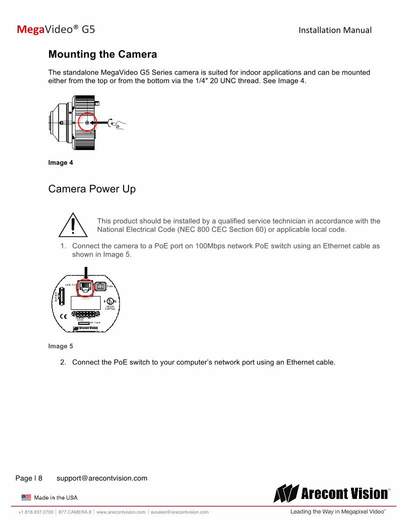
1. Connect the camera to a PoE port on 100Mbps network PoE switch using an Ethernet cable as shown in Image 5.
Image 5
2. Connect the PoE switch to your computer’s network port using an Ethernet cable.
3. If the camera is powered by an outside power supply, connect the power wires to the appropriate contacts of the 6-postion connector using a small flathead screwdriver and connect the 6-position plug to the camera as shown in Image 6.
NOTE 1: Ensure that the polarity of the DC input on the camera matches the way that wires are installed in the connector.
NOTE 2: AC power does not have polarity.
Image 6
Auxiliary Power If the camera is powered by a separate outside AC or DC power source, run the supplied power cable through the access hole on the camera housing and connect the power cable to the 2-position connector on the main camera board. The approximate location of the 2-position connector is circled in red below.
NOTE: Wiring methods shall be in accordance with the National Electrical Code/NFPA 70/ANSI, and with all local codes and authorities having jurisdiction. Wiring should be UL Listed and/or Recognized wire suitable for the application.
For use in ducts, plenums and other air-handling areas, replace Auxiliary Cable provided with CMP, CL2P or CL3P type wires.
Locally Storing Data Optional –S model configurations include a SDHC card slot for onboard storage. To set-up the SD card features, the Web Interface page or AV 200 can be used (see Camera Software Installation section for more details).
The camera supports class 10 microSD or microSDHC cards up to 32GB. Not all SD cards are the same. Arecont Vision highly recommends using SanDisk Extreme Micro SD cards (or an equivalent substitute) as these cards have been fully tested without issue. The SanDisk Extreme line is better suited for demanding applications like constant recording. Typical lower grade SD cards are meant for multimedia applications and will, at times, have questionable quality and reliability.
Recording to the SD card is FIFO (first in first out). The oldest (first) entry is deleted first as new storage requirements arise. There is no indication when this will happen. Storage time is dependent on a variety of factors such as SD card size and camera FPS.
SD Recording supports video only. Audio is not supported.
SD Card Set-up Insert an SD card (user supplied) into the SD card slot until it locks in place. The location of the SD card slot is shown in Image 7. The SD card can only be set-up via the Web Interface or AV200 Software.
Note: Upon insertion or removal of an SD card, the camera must be rebooted.
Camera Discovery, Setup, and Configuration For camera discovery and setup, the AV IP Utility is recommended. The software can be found on the CD included with your camera or at: http://www.arecontvision.com/softwares.php.
The AV IP Utility has the ability to provide multiple discovery options, including broadcast and multicast, check the status of a camera, change camera settings, import and export camera settings via a .csv file, and update firmware and/or hardware from virtually anywhere with a network connection.
Whether used for large installations that require an update to multiple settings, or smaller installations where only one camera needs changed, the AV IP Utility tool is efficient and convenient for mass or single camera uploads.
The AV IP Utility tool is compatible with all Arecont Vision® megapixel cameras. The user manual for the software is included on the CD that came with your camera or available on our website.
Network Protocols The Arecont Vision MegaVideo® G5 cameras support RTSP, RTP/TCP, RTP/UDP, HTTP, DHCP, TFTP, QoS, IP version 4 (IPv4) and IP version 6 (IPv6).
RTSP – Cameras communicate with video management systems over Real Time Streaming Protocol. Do not change the RTSP port unless you are sure your VMS does not use the default setting.
RTP/TCP – The Real-time Protocol/Transmission Control Protocol is best suited for applications that require high reliability, and transmission time is relatively less critical.
RTP/UDP – The Real-time Protocol/User Datagram Protocol is used for live unicast video, especially when it is important to always have an up-to-date video stream, even if some images are dropped.
HTTP – The Hypertext Transfer Protocol is an application protocol for distributed, collaborative, hypermedia information systems.
DHCP – The Dynamic Host Configuration Protocol allows network administrators to centrally manage and automate the assignment of IP addresses. DHCP should only be enabled if using dynamic IP address notification, or if the DHCP can update a DNS server.
TFTP – The Trivial File Transfer Protocol is a simple, lock-step, File Transfer Protocol which allows a client to get from or put a file onto a remote host. TFTP lacks security and most of the advanced features offered by more robust file transfer protocols such as File Transfer Protocol.
QoS – Quality of Service guarantees a certain level of a specified resource to selected traffic on a network. A QoS-aware network prioritizes network traffic and provides a greater network reliability by controlling the amount of bandwidth an application may use.
IPv4 – The IPv4 (IP version 4) is enabled by default and obtains the IP address automatically. The address can be used to allow or block network traffic that matches a specified address or protocol. The IP address must be valid for the network. For more information, contact your network administrator or call the Arecont Vision technical support hotline.
IPv6 – A typical IPv6 (IP version 6) node address consists of a prefix and an interface identifier (total 128 bits). The prefix is the part of the address where the bits have fixed values or are the bits that define a subnet. A typical IPv6 address may resemble the following example: 2001:db8: :52:1:1. The IP address must be valid for the network. Before making changes to the IPv6 address, consult with your network administrator or call the Arecont Vision technical support hotline.
SD Card Set-up via Web Interface
To set-up the SD card via the web interface, open your preferred web browser and type the camera’s IP address.
NOTE: For supporting H.264 streaming on a webpage, the recommended browsers are Internet Explorer and Firefox.
• Continuous Recording to start continuously recording.
• Stop Continuous Recording AND Enable Event-triggered Recording to enable events recording for network failure, motion alarm and/or I/O alarm trigger.
The Start and End times are visible once the camera starts recording (see image below). The start time represents the beginning time of the oldest recording.
Image 10
To playback recorded video:
• Input the date and time of the desired video (must be set between the Start and End time). • Check the Playback SD card video checkbox to play the video.
Playback tips:
Video recorded to an SD card from an Arecont Vision camera can only be played back via an Arecont Vision camera that has the same or lower resolution. Playback can not be viewed with any other device. For example, video recorded to an SD card via a 10MP camera can be played back on a 3MP camera but a 3MP can not be played back on a 10MP model.
Playback Allows the user to choose the specific time of video to playback.
Click to Play Button to play video specified in the Playback field.
Continuous Recording Allows the user to continuously record without restriction. Default is unchecked box.
Stop Continuous Recording AND Enable Event-triggered Recording
Allows the user to enable events recording when network failure, motion alarm, or an I/O alarm is triggered. Default is unchecked box.
NOTE: if the continuous recording is disabled and no event recording is enabled, the SD card will not initiate recording.
Network Failure Allows the SD Card to record video only in the event that the network fails.
Motion Alarm Allows the SD Card to record video only in the event that motion is detected.
I/O Alarm Allows the SD Card to record video only in the event that an I/O alarm is triggered.
Recording Framerate Allows setting a frame rate output limit for the H.264 video stream. Default value is “Max” minimum fps is 1. Reducing the frame rate output is another way to control the bandwidth used for the H.264 video streaming from the camera trade off is the obvious reduction of frame rate output at the camera. Options are 0 to 30. No default.
SD Card Image Resolution
Provides the ability to set the resolution. Options are Full or Half. Half is the default.
Start Shows the beginning time frame of the video being recorded. No default.
End Shows the ending time frame of the video being recorded. No default.
Delete All Records Allows the user to delete any previously recorded video on the SD card.
SD Card Setup via AV200 To set-up the SD card via AV200, launch the AV200 application icon on the desktop.
Image 12
To enable recording to the SD card, select the desired camera and drag it to the workspace to open a view. From the window, select the SD card drop down menu. Choose:
• Continuous Recording - OR -
• Event-triggered Recording to enable events recording for network failure, motion alarm or I/O alarm
Image 13
To launch the SD card playback window, click on the SD card icon.
Image 14
• Set play range to full span sets the playback range to the maximum available on the SD card.
• Set playback range allows the user to input the playback date and time manually.
• Export play exports an .avi file for playback on most media players.
Video recorded to an SD card from an Arecont Vision camera can only be played back via an Arecont Vision camera that has the same or lower resolution. Playback can not be viewed with any other device. For example, video recorded to an SD card via a 10MP camera can be played back on a 3MP camera but a 3MP can not be played back on a 10MP model.
Remote Zoom / Remote Focus via Web Interface To control the remote zoom / remote focus via the web interface, open your preferred web browser and type the camera’s IP address.
NOTE: For supporting H.264 streaming on a webpage, the recommended browsers are Internet Explorer and Firefox.
Numbers indicate the level of zooming or focusing in order to adjust the field-of-view.
To set-up a focus area (if necessary), draw a rectangle with the mouse (by left-clicking and dragging the mouse to a desired zoom size). To automatically adjust focus, choose “Full-range Focusing” or “Short-range Focusing” depending on the image clarity.
NOTE 1: “+20” zooms in 20x further than “+1”
NOTE 2: If the “Enable Auto Focus after Zoom” option is checked, the focus is automatically adjusted when the zoom is changed.
Full-range Focus Best for scenes that are completely out of focus. The camera automatically scans the full focus range of the scene to find the best focus position.
Short-range Focus Best for scenes that are slightly of out of focus. The camera quickly fine-tunes for a precise focus position.
Stop Stops any command in progress.
Focus Aid The higher the focus aid value means the more the lens is required to focus.
If the focus window box illuminates GREEN, the lens has reached its optimal focus level (see Image 9).
If the focus window box illuminates RED, the lens is having difficulty reaching an optimal focus level.
If the focus window box illuminates YELLOW, the focusing of the lens remains unchanged.
If the focus window box illuminates GREY, the focusing of the lens has been completed.
NOTE: Additional information regarding the Arecont Vision® web interface is found separately in the AV IP Utility Web Browser Manual via the Arecont Vision website.
Support 1. Arecont Vision FAQ Page Located at ArecontVision.com 2. Check the following before you call:
• Restore camera to factory default with AV200 or the camera webpage. • Upgrade to the latest firmware by visiting ArecontVision.com. • Isolate the camera on a dedicated network and test with AV200. • Swap the “troubled” camera with a known good camera to see if the problem follows the
camera or stays at the location. 3. Contact Arecont Vision Technical Support one of three ways: