21
MELAMINE DRYERS MELAMINE DRYERS MELAMINE DRYERS PRESENTATION
MELAMINE DRYERSMELAMINE DRYERS
MELAMINE DRYERS PRESENTATION
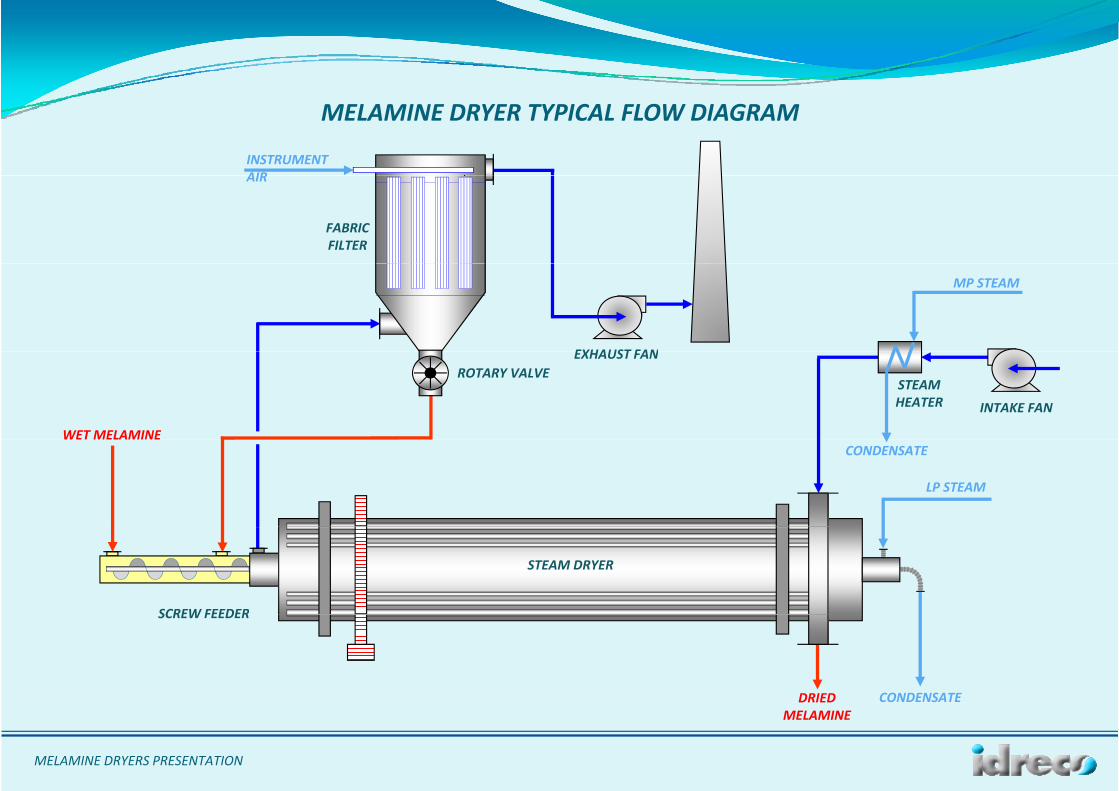
MELAMINE DRYER TYPICAL FLOW DIAGRAM
INSTRUMENTAIRAIR
FABRIC FILTER
EXHAUST FAN
MP STEAM
INTAKE FAN
EXHAUST FAN
WET MELAMINE
STEAMHEATER
ROTARY VALVE
WET MELAMINECONDENSATE
LP STEAM
SCREW FEEDER
STEAM DRYER
DRIED
SCREW FEEDER
CONDENSATE
MELAMINE DRYERS PRESENTATION
MELAMINE
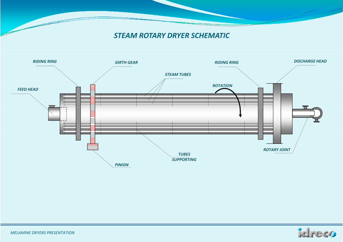
STEAM ROTARY DRYER SCHEMATIC
RIDING RING RIDING RINGGIRTH GEAR DISCHARGE HEAD
STEAM TUBES
FEED HEADROTATION
STEAM DRYER
ROTARY JOINTTUBES
SUPPORTINGPINION
MELAMINE DRYERS PRESENTATION
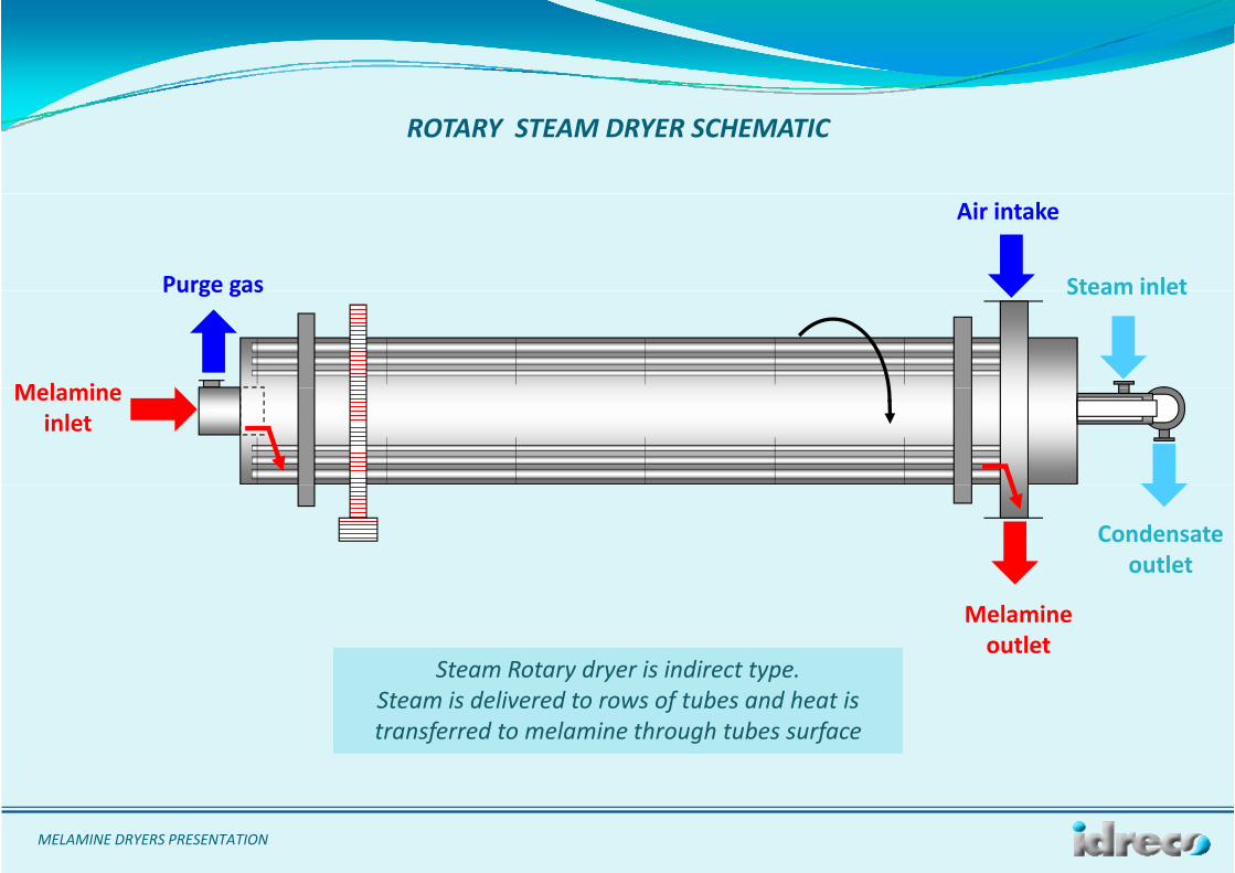
ROTARY STEAM DRYER SCHEMATIC
Purge gas
Air intake
Steam inletPurge gas
M l i
Steam inlet
STEAM DRYERMelamineinlet
Condensateoutlet
Steam Rotary dryer is indirect type.
Melamineoutlet
y y ypSteam is delivered to rows of tubes and heat istransferred to melamine through tubes surface
MELAMINE DRYERS PRESENTATION
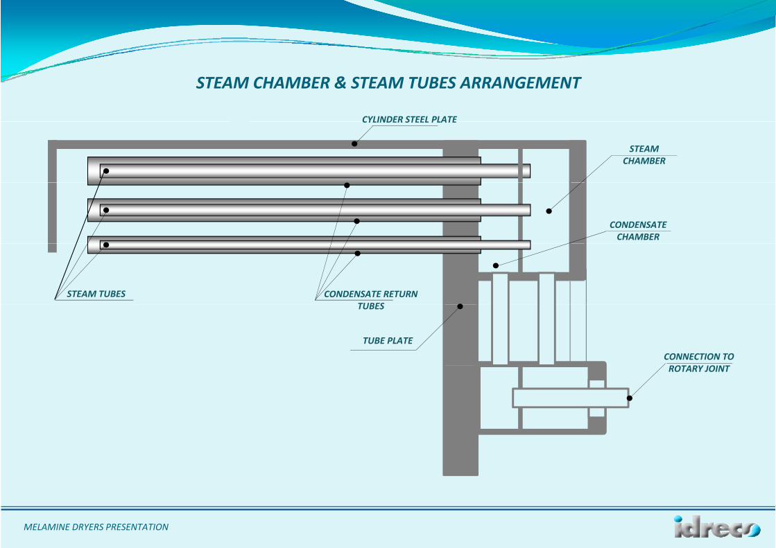
STEAM CHAMBER & STEAM TUBES ARRANGEMENT
CYLINDER STEEL PLATECYLINDER STEEL PLATE
STEAMCHAMBER
CONDENSATE CHAMBER
STEAM TUBES CONDENSATE RETURN TUBESTUBES
TUBE PLATE
CONNECTION TO ROTARY JOINT
MELAMINE DRYERS PRESENTATION
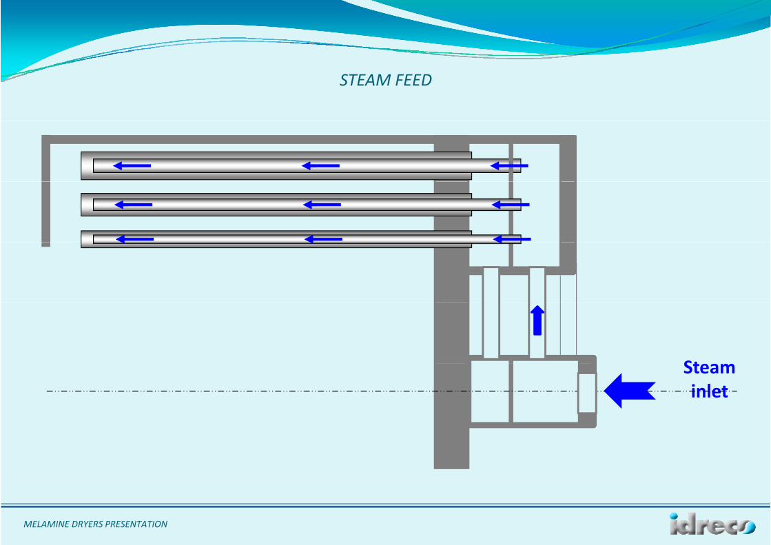
STEAM FEED
StSteaminlet
MELAMINE DRYERS PRESENTATION
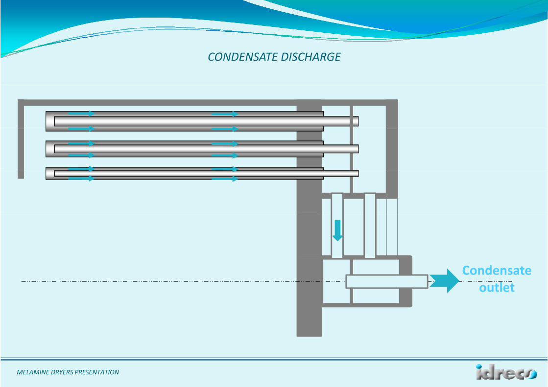
CONDENSATE DISCHARGE
Condensate outlet
MELAMINE DRYERS PRESENTATION
The rotary unit consists principally of a revolving cylinder, slightly inclined towards the discharge, supported by twolli i ti t t i ll h ith th t i ll b i t d t t l t l b O
STEAM DRYER DESCRIPTION
rolling rings resting on two trunnion rolls each, with the trunnion roll bearings mounted on structural steel bases. Onboth sides of one of the rolling rings there is an adjustable thrust roll for holding the cylinder in its longitudinal position.The cylinder is rotated by means of a girt gear meshing with a spur pinion mounted on the slow speed shaft of a speedreducer. The high speed shaft of the reducer is coupled to an electric motor through transmission and fluid coupling.g p p g p gOutside of cylinder at melamine feed side clamping bands with hammers are provided.The interior of the cylinder contains concentric rows of steam tubes bayonet type. At melamine feed side the externaltubes are closed with a cap and supported by spacers welded inside the shell. Along the length of the tubes,intermediate supports are providedintermediate supports are provided.At discharge side each tube is turned into a header. Each tube has a concentric steam distribution pipe.To prevent that the too wet melamine feed comes immediately in contact with the hot surfaces of the steam tubes acylindrical plate is layed over the tube in the melamine feed zone.Flight bars are welded to the cylinder adjacent to each tube to ensure intimate contact of material with the heattransfer surface. Steam is introduced to the header by means of a Johnson rotary joint (self supporting type) whichprovides also to evacuate condensate. At discharge end some openings in the cylinder allow discharge of the productinto the discharge breechinginto the discharge breeching.The breeching encloses the cylinder and bottom part is hoppered and flanged. The breeching face encircling thecylinder isequipped with a special friction type seal. The top of the breeching has a flanged opening for drying air inlet.At the melamine feed side, the cylinder is provided with a feed inlet head equipped with screw conveyor feeder andfl d i f i d l A l h ll b id d b f d i l h d d h f f hflanged opening for air and vapour removal. A seal shall be provided between feed inlet head and the face of thecylinder.
MELAMINE DRYERS PRESENTATION
MELAMINE M l i i l t i t 10 15 %
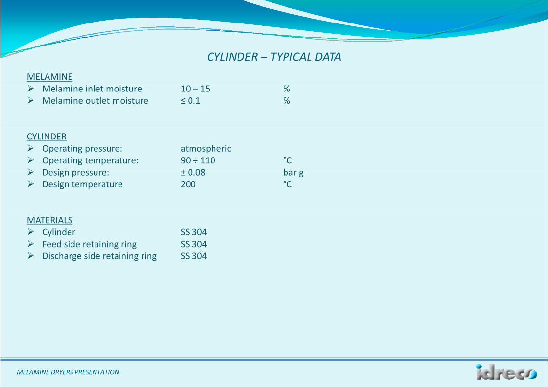
CYLINDER – TYPICAL DATA
Melamine inlet moisture 10 – 15 % Melamine outlet moisture ≤ 0.1 %
CYLINDER Operating pressure: atmospheric Operating temperature: 90 ÷ 110 °C Design pressure: ± 0 08 bar g Design pressure: ± 0.08 bar g Design temperature 200 °C
MATERIALS Cylinder SS 304 Feed side retaining ring SS 304 Discharge side retaining ring SS 304 Discharge side retaining ring SS 304
MELAMINE DRYERS PRESENTATION
PROCESS DATA St ti 8 b
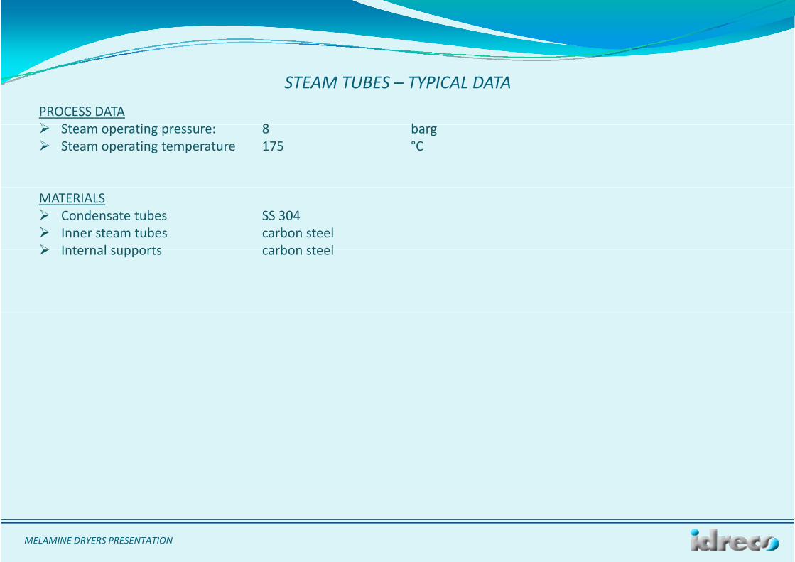
STEAM TUBES – TYPICAL DATA
Steam operating pressure: 8 barg Steam operating temperature 175 °C
MATERIALS Condensate tubes SS 304 Inner steam tubes carbon steel Internal supports carbon steel Internal supports carbon steel
MELAMINE DRYERS PRESENTATION
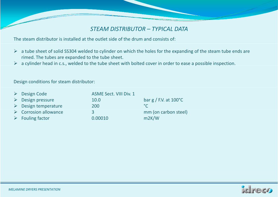
The steam distributor is installed at the outlet side of the drum and consists of:
STEAM DISTRIBUTOR – TYPICAL DATA
a tube sheet of solid SS304 welded to cylinder on which the holes for the expanding of the steam tube ends are rimed. The tubes are expanded to the tube sheet.
a cylinder head in c.s., welded to the tube sheet with bolted cover in order to ease a possible inspection.y , p p
Design conditions for steam distributor:
Design Code ASME Sect. VIII Div. 1 Design pressure 10.0 bar g / F.V. at 100°C Design temperature 200 °C Corrosion allowance 3 mm (on carbon steel) Fouling factor 0.00010 m2K/W
MELAMINE DRYERS PRESENTATION
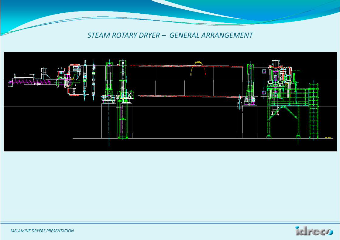
STEAM ROTARY DRYER – GENERAL ARRANGEMENT
MELAMINE DRYERS PRESENTATION
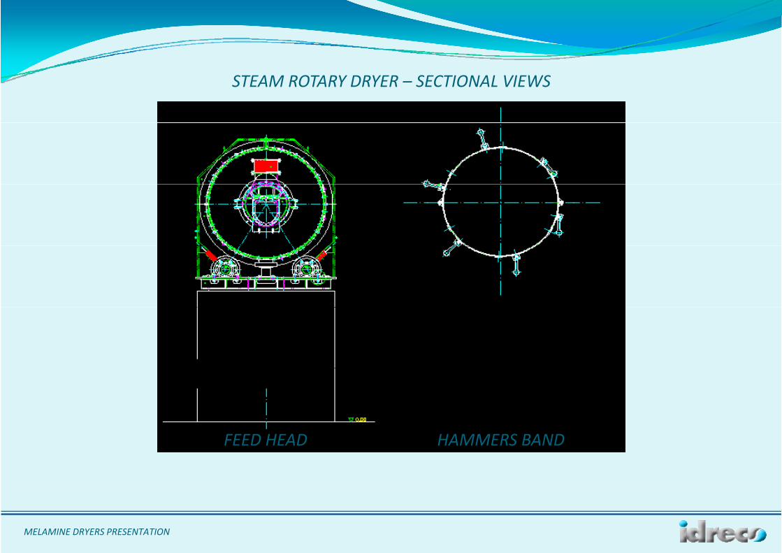
STEAM ROTARY DRYER – SECTIONAL VIEWS
FEED HEAD HAMMERS BAND
MELAMINE DRYERS PRESENTATION
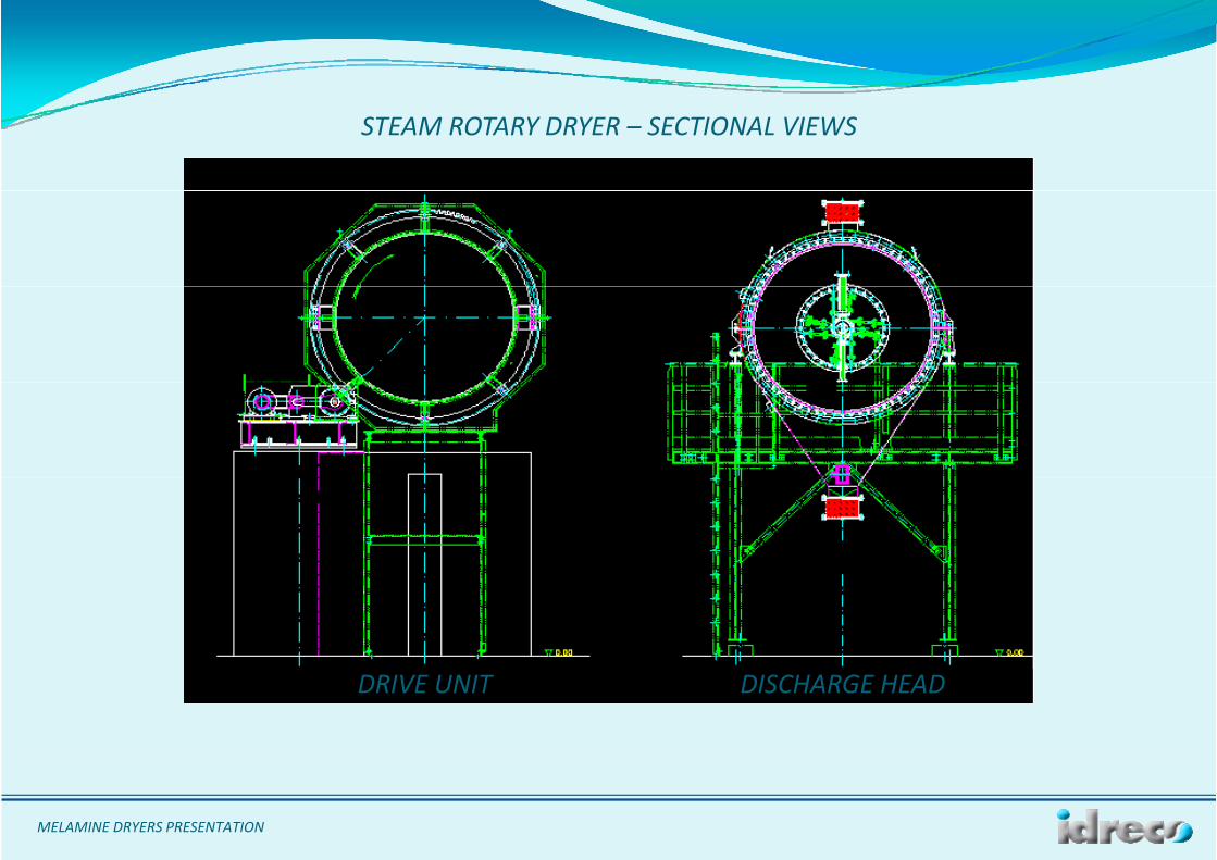
STEAM ROTARY DRYER – SECTIONAL VIEWS
DISCHARGE HEADDRIVE UNIT
MELAMINE DRYERS PRESENTATION
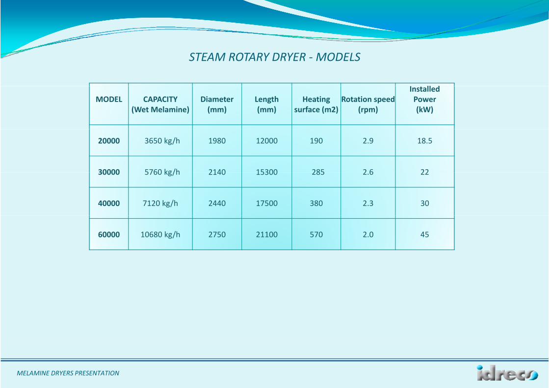
STEAM ROTARY DRYER ‐MODELS
ll dMODEL CAPACITY
(Wet Melamine)Diameter(mm)
Length(mm)
Heatingsurface (m2)
Rotation speed(rpm)
InstalledPower(kW)
20000 3650 kg/h 1980 12000 190 2.9 18.5
30000 5760 kg/h 2140 15300 285 2 6 2230000 5760 kg/h 2140 15300 285 2.6 22
40000 7120 kg/h 2440 17500 380 2.3 30
60000 10680 kg/h 2750 21100 570 2.0 45
MELAMINE DRYERS PRESENTATION
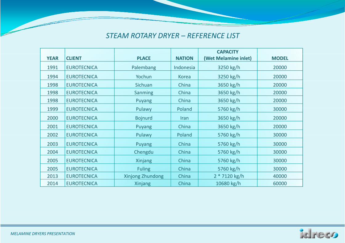
STEAM ROTARY DRYER – REFERENCE LIST
CAPACITY YEAR CLIENT PLACE NATION (Wet Melamine inlet) MODEL
1991 EUROTECNICA Palembang Indonesia 3250 kg/h 20000
1994 EUROTECNICA Yochun Korea 3250 kg/h 200001998 EUROTECNICA Sichuan China 3650 kg/h 200001998 EUROTECNICA Sanming China 3650 kg/h 200001998 EUROTECNICA Puyang China 3650 kg/h 20000
1999 EUROTECNICA P l P l d 5760 k /h 300001999 EUROTECNICA Pulawy Poland 5760 kg/h 30000
2000 EUROTECNICA Bojnurd Iran 3650 kg/h 20000
2001 EUROTECNICA Puyang China 3650 kg/h 200002002 EUROTECNICA Pulawy Poland 5760 kg/h 300002002 EUROTECNICA Pulawy Poland 5760 kg/h 30000
2003 EUROTECNICA Puyang China 5760 kg/h 300002004 EUROTECNICA Chengdu China 5760 kg/h 30000
2005 EUROTECNICA Xinjang China 5760 kg/h 300002005 EUROTECNICA Xinjang China 5760 kg/h 300002005 EUROTECNICA Fuling China 5760 kg/h 300002013 EUROTECNICA Xinjong Zhundong China 2 * 7120 kg/h 400002014 EUROTECNICA Xinjang China 10680 kg/h 60000
MELAMINE DRYERS PRESENTATION
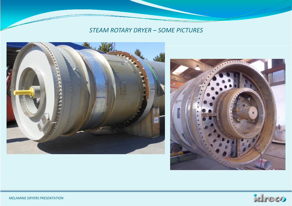
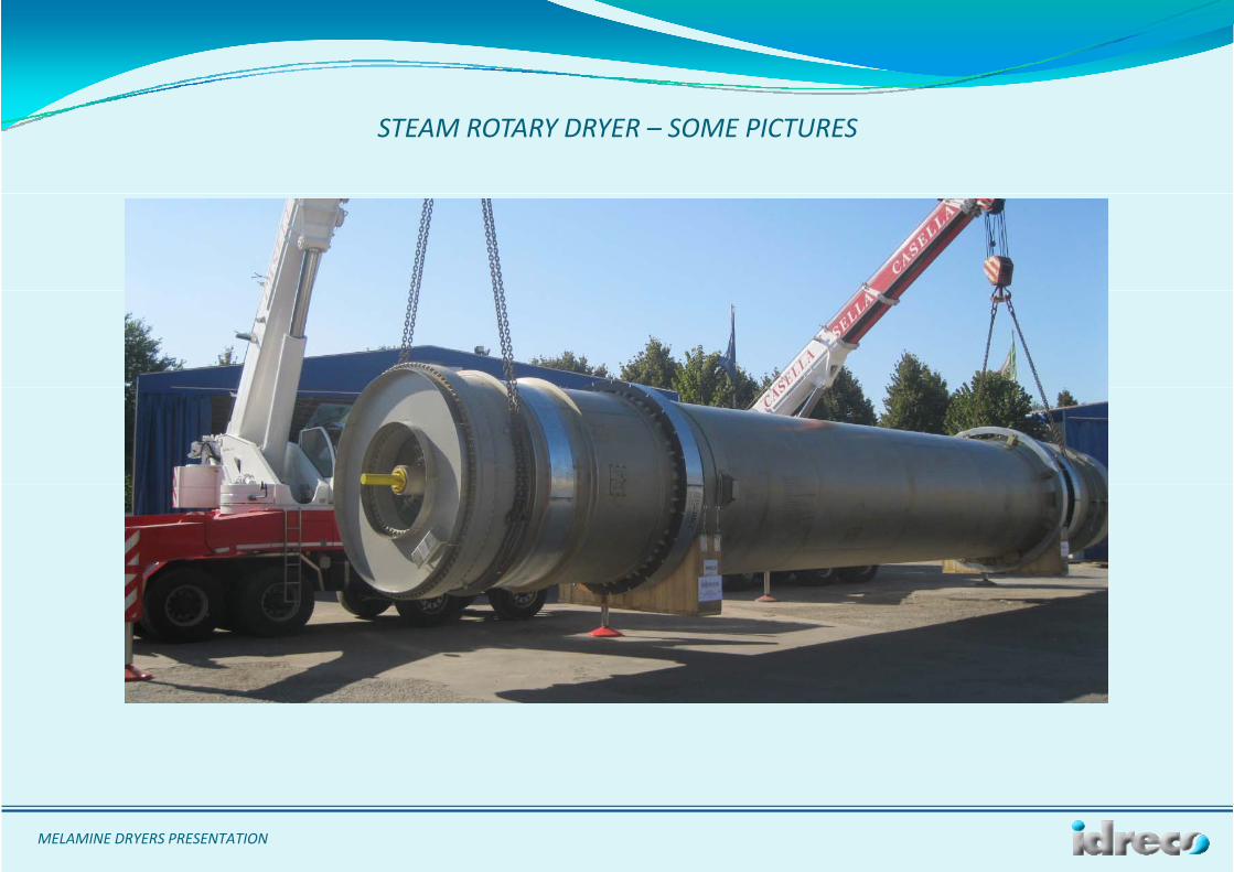
STEAM ROTARY DRYER – SOME PICTURES
MELAMINE DRYERS PRESENTATION
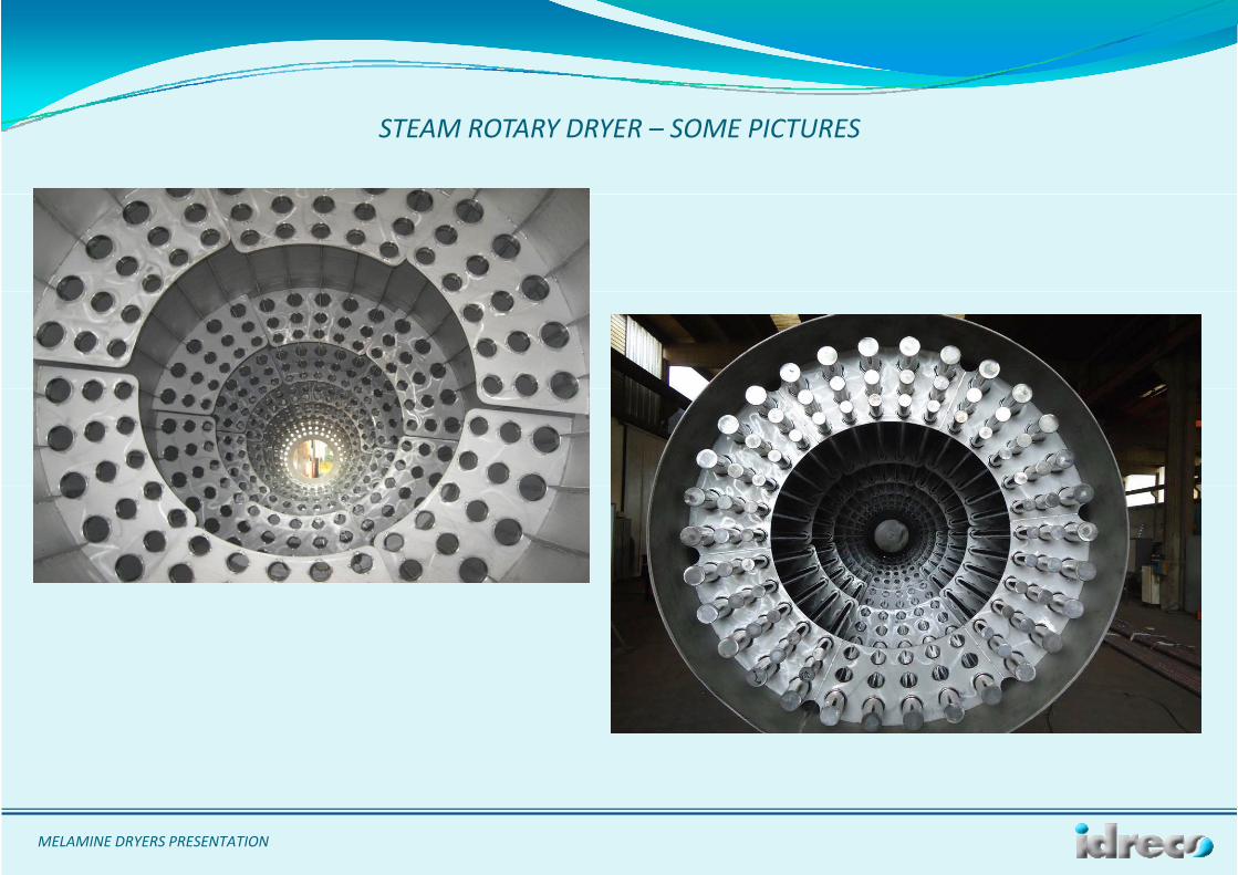
STEAM ROTARY DRYER – SOME PICTURES
MELAMINE DRYERS PRESENTATION
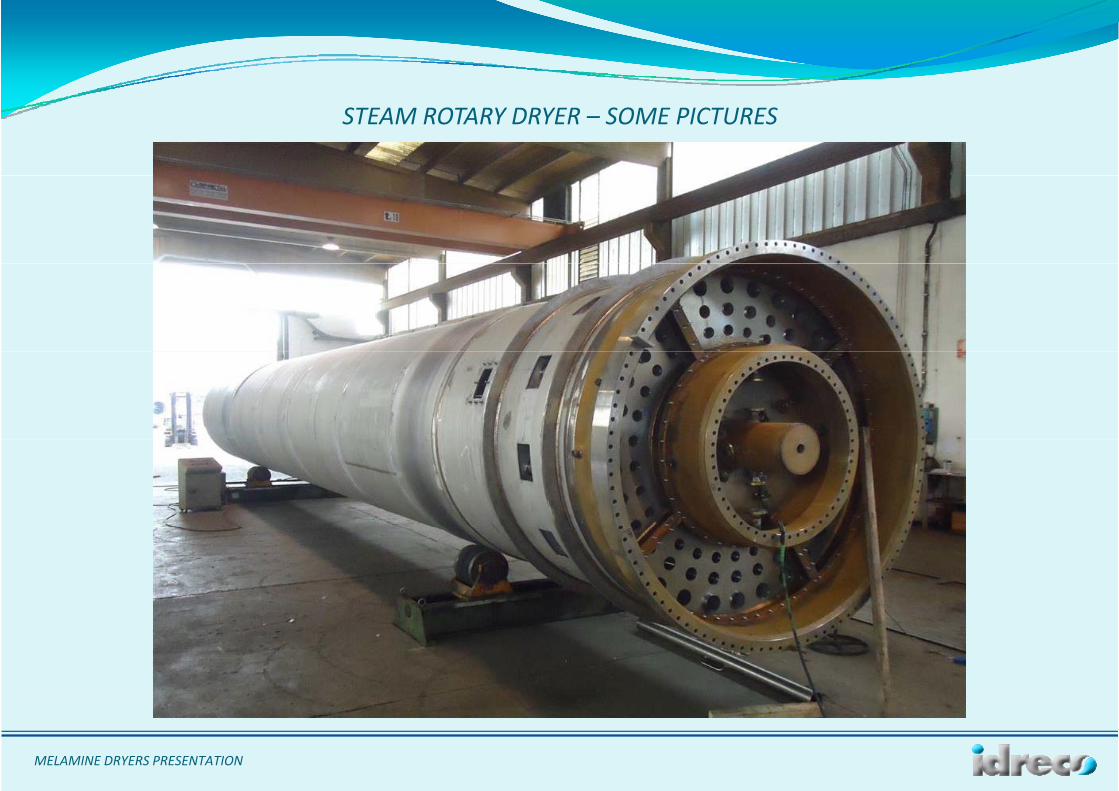
STEAM ROTARY DRYER – SOME PICTURES
MELAMINE DRYERS PRESENTATION
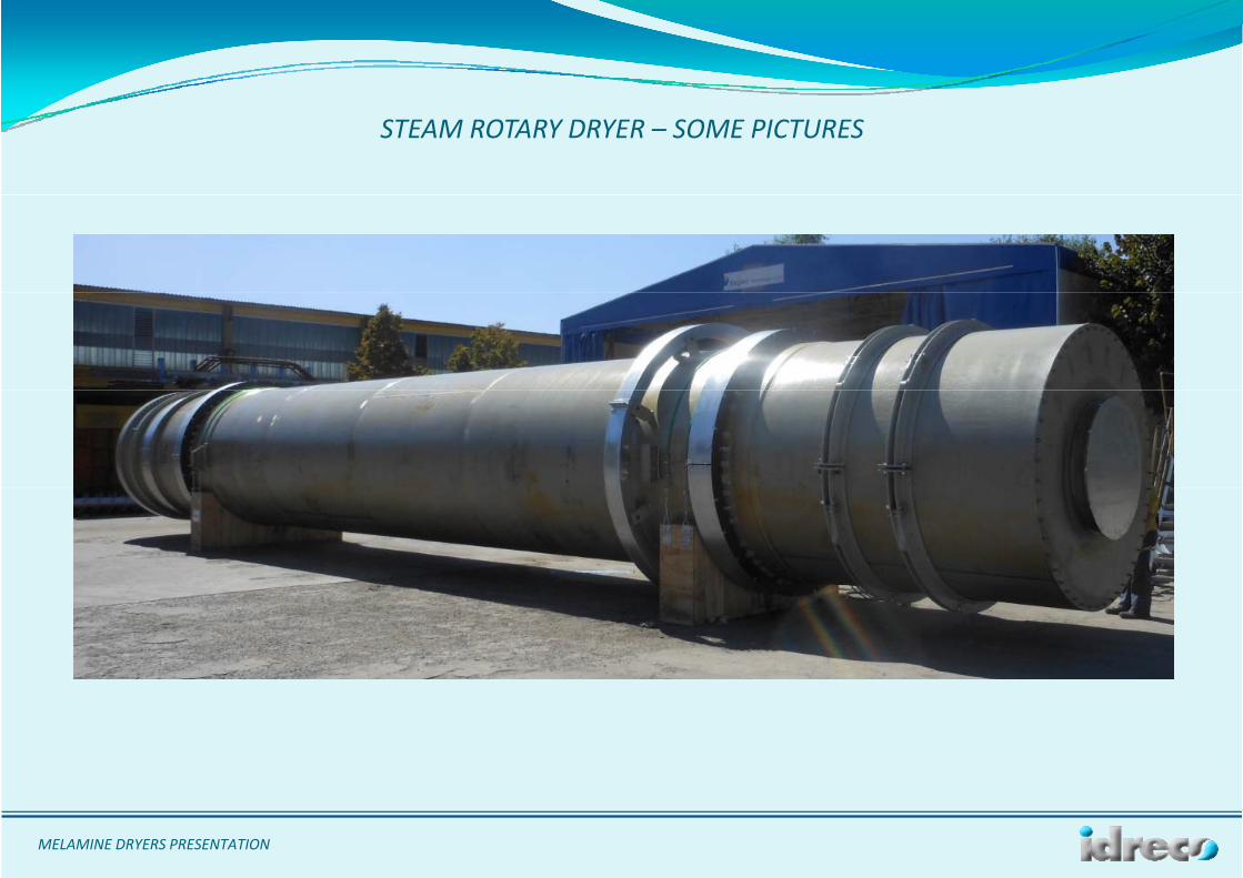
STEAM ROTARY DRYER – SOME PICTURES
MELAMINE DRYERS PRESENTATION
STEAM ROTARY DRYER – SOME PICTURES
MELAMINE DRYERS PRESENTATION


