12
MORRIS GROUP INTERNATIONAL R R SMITH SMITH MFG. CO. CUSTOMER DRIVEN SINCE 1926 MEMBER OF MORRIS GROUP INTERNATIONAL www.morrisgroup.co PROTECT YOUR INVESTMENTS Automatic Backwater Valve

MORRIS GROUPINTERNATIONAL
R
R
SMITH
SMITH MFG. CO.CUSTOMER DRIVEN
SINCE 1926
MEMBER OF MORRIS GROUP INTERNATIONAL
www.morrisgroup.co
P R O T E C T Y O U R I N V E S T M E N T S
A u t o m a t i c B a c k w a t e r Va l v e
R
Automatic Backwater Valve
FLOOD-GATE FEATURES
• Fully mechanical operation—no electricity required!
• Full port prevents obstruction of flow and trapped debris.
• In-Line Construction for easy installation in existing buildings.
• Positive Seal 99.9% effective in preventing leakage beyond the valve with 45 foot head of water pressure.
• Cast Iron Body and Stainless Steel Knife Gate for Long life and dependability.
FLOOD-GATE APPLICATIONS
Homes: Protect your investment from costly insurance claims.
Commercial: Basements, elevator pits, computer and electrical rooms to prevent costly downtime.
Industrial: Protect valuable machinery and equipment.
Institutional: Hospitals and schools to maintain maximum health environment.
Restaurants: Helps protect against bacterial contamination.
Properly installed, the FLOOD-GATE will provide years of trouble-free automatic service.
INDEx PAGE
Flood-Gate Featuresand Applications 2
How Flood-Gate Works 3
Flood-Gate Operation & Approvals 4
Valve Sizes, Rough-inDimensions & Options 5
Valve Installation 6
Special Installations 7
Flood-Gate Valve OptionalMonitoring System 8
Testing Instructions 9
Specifications 10
Illustration 11
P R O T E C T Y O U R I N V E S T M E N T S
2 www.jrsmith.com Jay R. Smith Mfg. Co. 800.467.6484

R
Automatic Backwater Valve
HOW THE FLOOD-GATE WORKS AUTOMATICALLY:
The Flood-Gate works to stop a sewerage backflow into a building. Backflows occur when there is a stoppage in the municipal/street sewer or septic system, causing the drainage water to rise above the top of the building’s drains.
As the sewer backflow occurs, the air trapped in the expansion chamber is compressed by sewage backup. The pressure in the expansion chamber causes the knife gate to rise until the 4” or 6” drainage opening is completely sealed. This action occurs with a 9” head of drainage water for a 4” valve and a 14” for a 6” valve. When complete closure is obtained in the valve, all backflow is prevented from entering the building or structure.
Once the backflow subsides andthe drainage water level returns tonormal, the counterweight atop theexpansion chamber forces the trapped air out of the chamber and into the drainage line, allowing the knife gate to lower to a full open position. Now the Flood-Gate is ready to guard against future backflow situations.
1
2
3
P R O T E C T Y O U R I N V E S T M E N T S
www.jrsmith.com Jay R. Smith Mfg. Co. 800.467.6484 3
R
Automatic Backwater Valve
FLOOD-GATE OPERATION AND APPROVALS
OPERATION:
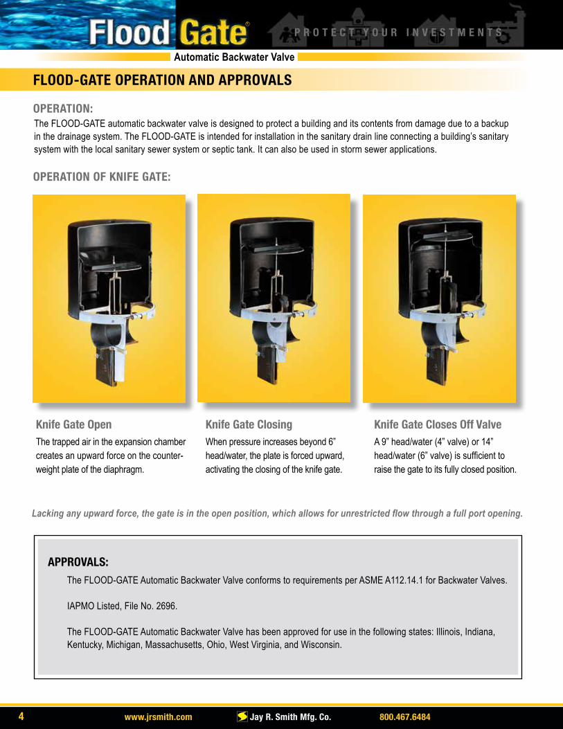
OPERATION OF KNIFE GATE:
The FLOOD-GATE automatic backwater valve is designed to protect a building and its contents from damage due to a backup in the drainage system. The FLOOD-GATE is intended for installation in the sanitary drain line connecting a building’s sanitary system with the local sanitary sewer system or septic tank. It can also be used in storm sewer applications.
Lacking any upward force, the gate is in the open position, which allows for unrestricted flow through a full port opening.
APPROVALS: The FLOOD-GATE Automatic Backwater Valve conforms to requirements per ASME A112.14.1 for Backwater Valves.
IAPMO Listed, File No. 2696.
The FLOOD-GATE Automatic Backwater Valve has been approved for use in the following states: Illinois, Indiana, Kentucky, Michigan, Massachusetts, Ohio, West Virginia, and Wisconsin.
Knife Gate OpenThe trapped air in the expansion chamber creates an upward force on the counter-weight plate of the diaphragm.
Knife Gate ClosingWhen pressure increases beyond 6”head/water, the plate is forced upward,activating the closing of the knife gate.
Knife Gate Closes Off ValveA 9” head/water (4” valve) or 14”head/water (6” valve) is sufficient toraise the gate to its fully closed position.
P R O T E C T Y O U R I N V E S T M E N T S
4 www.jrsmith.com Jay R. Smith Mfg. Co. 800.467.6484

R
Automatic Backwater Valve
FLOOD-GATE VALVE, DIMENSIONS AND OPTIONS
See page 14 for dimensions
FLOOD-GATE VALVE 7140Y04 4 in. (100 mm), 60 lbs. 7140Y06 6 in. (150 mm), 90 lbs.
U.S. Patent No. 5,538,032Other U.S. and foreign patents pending
FLOOD-GATE PIT
- FGP (Poly Pit, secured, Gasketed Poly Lid, Hardware), 25 lbs. - FGS (Poly Pit, secured, Gasketed Steel Lid, Hardware), 69 lbs. - FGSL Steel Lid Only, 42 lbs. NOTE: All Flood-Gate Pits (are furnished withtwo pipe gasket seals) - designate 4” or 6” valve.Pit can only be located in non-traffic areas.
FLOOD-GATE ALARM - FGA • Alarm Control Box • 35 ft. of Cable • Sensor • One (1) 9 volt battery* and/or 120 volt A/C power plug *9 volt battery not included
P R O T E C T Y O U R I N V E S T M E N T S
www.jrsmith.com Jay R. Smith Mfg. Co. 800.467.6484 5

R
Automatic Backwater Valve
FLOOD-GATE VALVE INSTALLATION: 4 INCH (7140Y04) & 6 INCH (7140Y06)
PIPING OPTION ONE:Install the FLOOD-GATE n the horizontal drain line between the building and the sewer main. Although this provides complete protection from flooding, all of the plumbing fixtures in the building will be out of service once the FLOOD-GATE is activated. The optional alarm system is highly recommended with this type of installation
PIPING OPTION TWO:Install the FLOOD-GATE where only the fixtures installed below grade (as in a basement) are connected on the upstream side of the valve. Fixtures installed above grade are connected on the downstream (sewer) side of the valve, allowing continued use of the above grade fixtures, while protecting below grade areas from flooding.
PIT INSTALLATION:When the FLOOD-GATE is partially recessed or fully recessed, it must be installed in a ventilated and permanently dry (water-free) access pit in the horizontal drain line between the building and the sewer main (a sealed or flooded pit will restrict the free movement of the valve).
CRITICAL INSTALLATION DATA:The distance from the top of the horizontal drain line, where the FLOOD-GATE is installed, to the top of basement floor drain must be AT MINIMUM 9 inches for MODEL # 7140Y04 and 14 inches for MODEL # 7140Y06. An additional two (2) inches more than this minimum is suggested, so that the top of the valve cover will be situated 2” below the pit cover.
FACTORY TESTED:The FLOOD-GATE VALVE must be properly installed with the proper direction of flow (as indicated by the arrows on the valve) to ensure proper functioning. Each FLOOD-GATE valve has been thoroughly inspected and tested at the factory. If the valve is damaged during shipment, or if any service to the valve is necessary, return the complete valve to the factory for repair or replacement. DO NOT attempt to disassemble or repair the FLOOD-GATE in the field.
MAINTENANCE:On a quarterly basis, manually open and close the valve three or four times to exercise the bellows in the valve housing. To do this: 1. Insert the maintenance T-handle through the hole located in the center of the top of the valve cover; attach it to the threaded stem located on the top of the counterweight top. 2. Pull the handle up slowly until it stops. 3. Release the handle and allow it to return to the original position. 4. Repeat steps 2 and 3 until you have completed the action three or four times. 5. Remove the maintenance handle.
The FLOOD-GATE automatic backwater valve is designed to protect a building from flood damage due to a backup in thesanitary sewer system and can also be used in storm sewer applications. Properly installed, the FLOOD-GATE will provide years of trouble-free automatic service. Depending on individual circumstances, one of the two following installation guidelines must be followed:
View looking at a Flood-Gate installation.
View of Flood-Gate in plastic pit with gravel ballest.
View of a Flood-Gate installed in a 4 - foot deep concrete pit .
P R O T E C T Y O U R I N V E S T M E N T S
6 www.jrsmith.com Jay R. Smith Mfg. Co. 800.467.6484

R
Automatic Backwater Valve
FLOOD-GATE SYSTEM SPECIAL INSTALLATIONS
Detail - in-line backwater valve and sewage pump
Detail - in-line backwater valve and sewage pump
P R O T E C T Y O U R I N V E S T M E N T S
www.jrsmith.com Jay R. Smith Mfg. Co. 800.467.6484 7

R
Automatic Backwater Valve
INSTALLATION INSTRUCTIONS:The monitoring system consists of two parts: the sensor and the monitor. TO INSTALL:
1. Mount the sensor to the top of the valve cover with the two 1 1/4” and two 5/8” self-tapping screws provided. Once this is accomplished and the sensor has been mounted properly to the valve cover, the rod should penetrate the hole in the top of the valve cover and the sensor should be approximately 1 1/2” offset of the hole.
2. Attach the sensor wire to the alarm using the screw terminals without an active external power source. (Do not apply power) Route the cable from the sensor to the alarm. Using a Phillips head screwdriver, attach the sensor power cord to the screw terminals located on the base of the alarm, disregarding wire color. Screw the alarm onto the wall using the mounting flange located at the base of the alarm.
3. Insert one (1) 9-volt battery and/or attach the provided 120 V A/C power cord. The alarm/monitoring system is now operational. Proper operation can be verified using the test procedure included with the Flood-Gate alarm option. When the valve closes, the audible and visual alarm should activate.
FEATURES: • Automatic alarm reset • UL listed components • CSA Certified
• Alarm horn sounds at 87 decibels at 10 feet. • Low battery chirp • Red “alarm” light and green” power on” light, alarm “test” switch, and horn “silence” switch.
• Auxiliary dry contacts for any UL listed mechanism.
FLOOD-GATE VALVE OPTIONAL MONITORING SYSTEM
P R O T E C T Y O U R I N V E S T M E N T S
INDICATOR MEANINGS: Green light on Power On with 120 V A/C plug being used Red light on Flood in progress, operation of water fixtures in building should cease. Audio alarm is sounded. Press the silence button to silence alarm. Red light remains on. No lights 9-volt battery being used, 120 V A/C power plug being used/loss of power supply. Press test button to check monitoring system. Low battery chirp Indicates battery should be replaced.
8 www.jrsmith.com Jay R. Smith Mfg. Co. 800.467.6484

R
Automatic Backwater Valve
FLOOD-GATE TESTING INSTRUCTIONS AND ILLUSTRATION
1. Place a “Test Ball” through the main cleanout into the horizontal drain line and inflate it.
2. With an ordinary garden hose, run water into the building drain through the cleanout opening (this will simulate a backup of the main sewer).
3. Watch the round opening in the top of the FLOOD-GATE VALVE cover. You should see the end of the valve stem rise as the valve closes. Full closure should occur before the water in the cleanout opening reaches floor level. This means the valve is closing properly.
4. Deflate the “Test Ball.” This will allow the drain to open and you should be able to see the valve stem drop; returning to its normal open position.
IMPORTANT: THIS PROCEDURE MUST BE FOLLOWED AFTER THE INITIAL INSTALLATION.
MINIMUM BURY DEPTH
MODEL # 7140Y04 X= 9 inchesMODEL # 7140Y06 X=14 inches
NOTE: X = The dimension from the top of the horizontal drain line to the top of basement floor drain.
NOTE: It is important to test the FLOOD-GATE after long periods of inactivity to assure readiness. Follow these instructions to test for proper operation.
P R O T E C T Y O U R I N V E S T M E N T S
www.jrsmith.com Jay R. Smith Mfg. Co. 800.467.6484 9

R
Automatic Backwater Valve
FLOOD-GATE SPECIFICATIONS
Backwater Valve for gravity sanitary drainage system connected to municipal sanitary sewers or septic tanks.
The assembly comprises numerous parts. The following is a brief description of the main components.
1. Gate - Manufactured from type 304stainless steel with full port opening and integral closing stopper.
2. Body - Two cast iron halves, designed tobolt together to enclose gate. Cast iron shallbe Class 25 to ASTM A48. Both sections areequipped with barrels suitable for mechanical coupling to upstream and downstream sections of pipe. Out (or downstream) fittingequipped with full port opening. Each half incorporates a continuous groove around thecircumference of the opening to accept an O-ring. These O-rings act to seal against the gate.
3. Spacer - A stainless steel gasket is placed between the two body halves to permit the (thinner) gate to slide within the two halvesof the body.
4. Expansion chamber - Flexible PVC diaphragm.
5. Counterweight Plate, Plate Weight Holder, and Rod - Counterweight Plate is affixed to the top of the expansion chamber using a threaded rod equipped with nuts. The nuts compress the top surface of the expansion chamber between the counter-weight plate on top and the plate weight holder on the bottom. The rod is connected to the top of the gate. Expansion chamberCounterweight Plate is made of cast iron.
6. Clamping Ring - Clamps the bottom skirt of the expansion chamber to the circumference of the body, forming a watertightseal. This seal prevents wastewater that enters the expansion chamber through the downstream port under surcharge conditions from leaking out of the expansion chamber.
7. Cover - Polyethylene cylinder which is positioned over the expansion chamber to protect it and constrain its expansionunder surcharge conditions.
8. Maintenance Handle - Tee shaped handle used to attach to stem in center of the counterweight plate to exercise valveduring quarterly maintenance. The maintenance handle MUST be removed at the completion of required maintenance or the unit will not function properly.
APPLICATION:
MATERIAL SPECIFICATIONS:
P R O T E C T Y O U R I N V E S T M E N T S
10 www.jrsmith.com Jay R. Smith Mfg. Co. 800.467.6484

R
Automatic Backwater Valve
FLOOD-GATE ILLUSTRATION
Cover
CounterweightPlate and Rod
Flexible PVCExpansionChamber
StainlessSteel Gate
ClampingRing
Spacer
Body
Drawing for illustration purposes only.
P R O T E C T Y O U R I N V E S T M E N T S
www.jrsmith.com Jay R. Smith Mfg. Co. 800.467.6484 11

SPM0216-1305
MORRIS GROUP INTERNATIONAL
ACORN ENGINEERING COMPANY Engineered Plumbing Products P.O. Box 3527 • City of Industry, CA 91744-0527 U.S.A.800-488-8999 • 626-336-4561 www.acorneng.com
ACORN-GENCON PLASTICS, LLCInjection Molded Products13818 Oaks Avenue • Chino, CA 91710 U.S.A.Tel: 909-591-8461www.acorn-gencon.com
ACORNVAC, INC. Vacuum Plumbing Systems13818 Oaks Avenue, Chino, CA 91710 U.S.A.Tel: 800-591-9920 • Tel: 909-902-1141www.acornvac.com
CHRONOMITE LABORATORIES, INC.Tankless Electric Water HeatersP.O. Box 3527 • City of Industry, CA 91744-0527 U.S.A.Tel: 800-447-4962www.chronomite.com
ELMCO GROUPManufacturer RepresentativesP.O. Box 3787, City of Industry, CA 91744 U.S.A.Tel: 626-333-9942 www.morrisgroup.co
MORRIS INdUSTRIES MExICO, S. dE R.L. dE C.V.Central and Latin America Manufacturing and SalesMaquiladoras #1387-1 Col.Cd. Industrial Tijuana, B.C., C.P. 22444Tel: 011-52-664-623-4580 www.morrisgroup.co
MORRIS PROPERTY MANAGEMENT COMPANYConstruction, Interior Design, Landscaping and Maintenance15058 Proctor Avenue • City of Industry, CA 91746 U.S.A.Tel: 626-855-4888 www.morrispropertiesmgt.com
MURdOCk MANUFACTURINGDrinking Fountains and HydrantsP.O. Box 3527 • City of Industry, CA 91744-0527 U.S.A.Tel: 800-45-DRINK • 626-333-2543 www.murdockmfg.com
POTTER ROEMER Fire Protection EquipmentP.O. Box 3527 • City of Industry, CA 91744-0527 U.S.A.Tel: 800-366-3473www.pot terroemer.com
WHITEHALL MANUFACTURINGHospital and Rehabilitation ProductsP.O. Box 3527 • City of Industry, CA 91744-0527 U.S.A.Tel: 800-782-7706 • 626-968-6681www.whitehallmfg.com
Innovative Spirit and
Engineering Foundation
“What sets us apart from competitors is
our engineering and spirit. We have a
can-do’ spirit. If you ask us to do
something, we will do it or figure
out how to do it. That’s the part our
customers like, that’s the part we like.”
- Don Morris, President and CEO
JAY R. SMITH MFG. CO.®
Plumbing and Drainage ProductsP.O. Box 3237 • Montgomery, AL 36109-0237Tel: 800-467-6484 • 334-277-8520 www.jrsmith.com


