Dew point indicator visually confirms air drying (Except IDG1) (Optional on IDG3, IDG5, IDG3H, IDG5H) • Compact • Lightweight • Space-saving Environmentally friendly (non-freon) Compatible with low dew points Discharged air noise reduced with built-in silencer Type with fitting to purge air is also available. When purge air discharge is undesirable in the area around the membrane air dryer, it can be discharged to atmosphere via tubing (option). ( ) Dew point indicator Fitting to exhaust purge air for dew point checker Purge air discharge fitting for dehumidification IDG1 Flexible piping is possible Low flow rate type tube configuration Outlet air flow: 10 l/min (ANR) Unit type Integrated prefilter and regulator Mist separator + Micro mist separator + IDG Micro mist separator with prefilter + IDG Mist separator + Micro mist separator + IDG Micro mist separator with prefilter + IDG + Regulator + Regulator Type M Type V Except IDG1, IDG3, IDG3H, IDG5, IDG5H, IDG30, IDG30H, IDG30L, IDG50, IDG50H, IDG50L Power supply not required No power supply is necessary. Wiring labor is not required and there is no need to consider electrical standards, etc. Series IDG Membrane Air Dryer No vibration or heat discharge There are no mechanical moving parts as in the case of refrigeration equipment. 89 Outlet air atmospheric pressure dew point: – 40°C (IDG30L, IDG50L, IDG60L, IDG75L, IDG100L) Outlet air atmospheric pressure dew point: – 60°C (IDG60S, IDG75S, IDG100S) Dehumidification principle Orifice Hollow fiber Dry air Purge air Air (oxygen, nitrogen, etc.) Moisture Humid compressed air Application example The membrane air dryer uses hollow fibers composed of a macro molecular membrane through which moisture passes easily, but is difficult for air (oxygen and nitrogen) to pass through. When humid, compressed air is supplied to the inside of the hollow fibers, only moisture permeates the membrane and moves to the outside due to the pressure difference between the moisture inside and outside of the fibers. The compressed air becomes dry air and continues out of the dryer. Part of the dry air from the outlet side is passed through a very small orifice to reduce the pressure and purge the outside of the hollow fibers. The moisture which permeated to the outside of the hollow fibers is discharged to the atmosphere by this purge air. In this way, the partial pressure outside of the hollow fibers remains low and dehumidification is continuously performed. • Machine tools (air bearings, lasers, etc.) • Precision measuring equipment (3-D measuring machines) • Semiconductor manufacturing equipment • Semiconductor inspection equipment • Dental equipment • Chemical analysis equipment • Ozonizers, Hydrogen gas generating equipment • Packaging machines, Paper making machines, Food processing machines • Printed circuit board IC mounting machines • Fine particle drying, Transfer equipment • Electrostatic and high grade coating • Drying and cleaning of precision parts • Condensation prevention in control panels • General pneumatic equipment and pneumatic tools AT IDFA IDFB ID IDG AMG AFF AM AMD AMH AME AMF SF SFD LLB ADGD HAA HAW IDF IDU Courtesy of Steven Engineering, Inc.-230 Ryan Way, South San Francisco, CA 94080-6370-Main Office: (650) 588-9200-Outside Local Area: (800) 258-9200-www.stevenengineering.com
Transcript
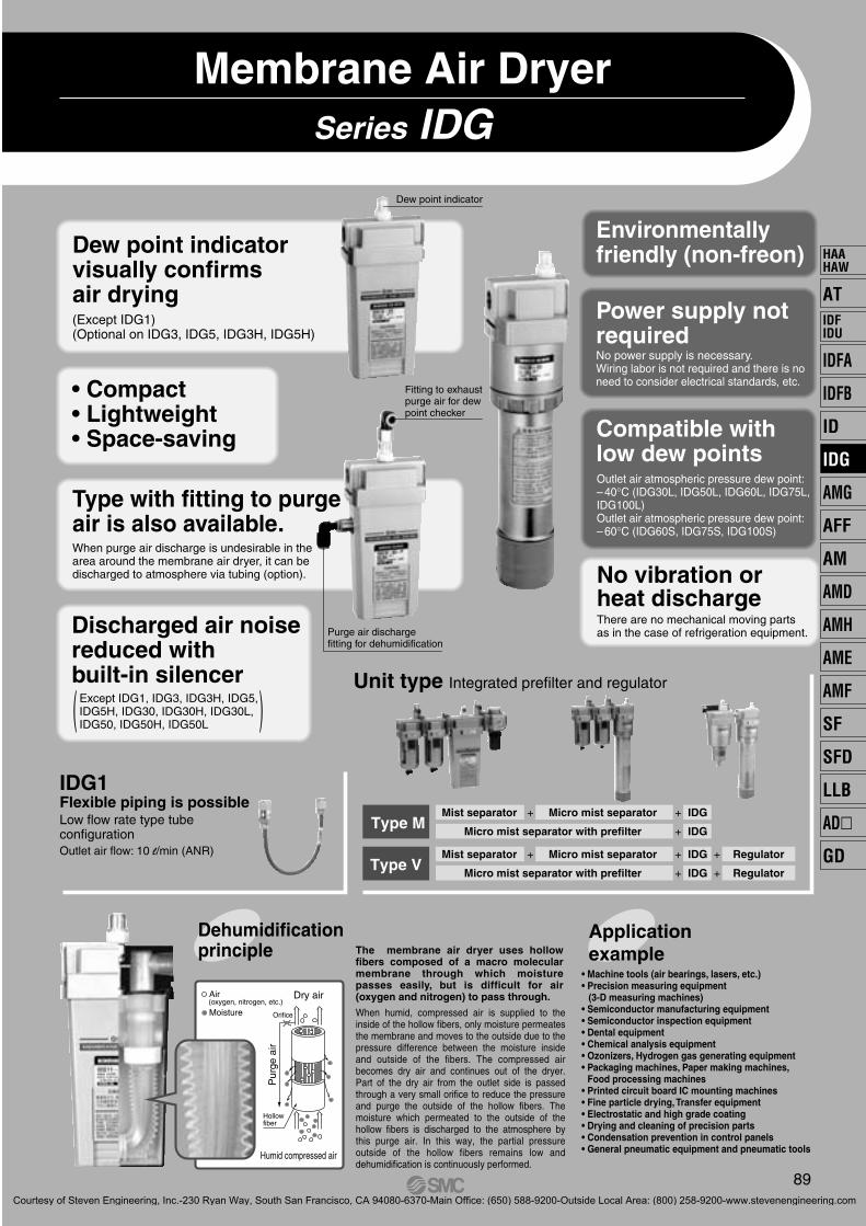
Dew point indicator visually confirms air drying(Except IDG1)(Optional on IDG3, IDG5, IDG3H, IDG5H)
• Compact• Lightweight• Space-saving
Environmentallyfriendly (non-freon)
Compatible with low dew points
Discharged air noisereduced with built-in silencer
Type with fitting to purge air is also available.When purge air discharge is undesirable in the area around the membrane air dryer, it can be discharged to atmosphere via tubing (option).
( )
Dew point indicator
Fitting to exhaustpurge air for dew point checker
Purge air dischargefitting for dehumidification
IDG1Flexible piping is possibleLow flow rate type tube configurationOutlet air flow: 10 l/min (ANR)
ApplicationexampleThe membrane air dryer uses hollow
fibers composed of a macro molecular membrane through which moisture passes easily, but is difficult for air (oxygen and nitrogen) to pass through.
When humid, compressed air is supplied to the inside of the hollow fibers, only moisture permeates the membrane and moves to the outside due to the pressure difference between the moisture inside and outside of the fibers. The compressed air becomes dry air and continues out of the dryer. Part of the dry air from the outlet side is passed through a very small orifice to reduce the pressure and purge the outside of the hollow fibers. The moisture which permeated to the outside of the hollow fibers is discharged to the atmosphere by this purge air. In this way, the partial pressure outside of the hollow fibers remains low and dehumidification is continuously performed.
• Semiconductor manufacturing equipment• Semiconductor inspection equipment• Dental equipment• Chemical analysis equipment• Ozonizers, Hydrogen gas generating equipment• Packaging machines, Paper making machines,
Food processing machines• Printed circuit board IC mounting machines• Fine particle drying, Transfer equipment• Electrostatic and high grade coating• Drying and cleaning of precision parts• Condensation prevention in control panels• General pneumatic equipment and pneumatic tools
AT
IDFA
IDFB
ID
IDG
AMG
AFF
AM
AMD
AMH
AME
AMF
SF
SFD
LLB
AD�
GD
HAAHAW
IDFIDU
P0089-P0140-E.qxd 08.11.6 1:45 PM Page 89
Courtesy of Steven Engineering, Inc.-230 Ryan Way, South San Francisco, CA 94080-6370-Main Office: (650) 588-9200-Outside Local Area: (800) 258-9200-www.stevenengineering.com
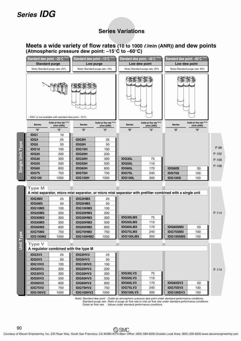
∗ IDG1 is not available with standard dew point –15°C.
Outlet air flow rate Note)
(l/min (ANR))Outlet air flow rate Note)
(l/min (ANR)) SeriesOutlet air flow rate Note)
(l/min (ANR))
Meets a wide variety of flow rates (10 to 1000 l /min (ANR)) and dew points(Atmospheric pressure dew point: –15°C to –60°C)
Standard dew point: –20°C Note)
Low purge
Note) Standard purge rate: 10%
Standard dew point: –15°C Note)
Low dew point
Note) Standard purge rate: 25%
Standard dew point: –40°C Note)
Low dew point
Note) Standard purge rate: 35%
Standard dew point: –60°C Note)
Un
it T
ype
Sin
gle
Un
it T
ype
Type M A mist separator, micro mist separator, or micro mist separator with prefilter combined with a single unit
Type V A regulator combined with the type M
Note) Standard dew point : Outlet air atmospheric pressure dew point under standard performance conditionsStandard purge rate : Ratio of purge air flow rate to inlet air flow rate under standard performance conditionsOutlet air flow rate : Values under standard performance conditions
P0089-P0140-E.qxd 08.11.6 1:45 PM Page 90
Courtesy of Steven Engineering, Inc.-230 Ryan Way, South San Francisco, CA 94080-6370-Main Office: (650) 588-9200-Outside Local Area: (800) 258-9200-www.stevenengineering.com
91
AT
IDFA
IDFB
ID
IDG
AMG
AFF
AM
AMD
AMH
AME
AMF
SF
SFD
LLB
AD�
GD
HAAHAW
IDFIDU
P0089-P0140-E.qxd 08.11.6 1:45 PM Page 91
Courtesy of Steven Engineering, Inc.-230 Ryan Way, South San Francisco, CA 94080-6370-Main Office: (650) 588-9200-Outside Local Area: (800) 258-9200-www.stevenengineering.com
Atmospheric pressure dew point (°C)
Pre
ssur
e de
w p
oint
(°C
)
0
10
20
30
40
50
60
–60 –50
–60
–50
–40 –30
–40
–30
–20
–10
–20 –10 0 10 20 30
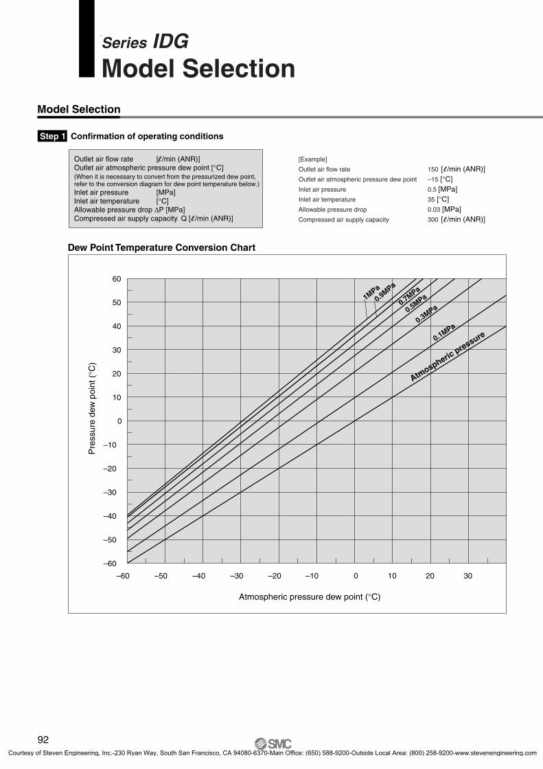
Dew Point Temperature Conversion Chart
Outlet air flow rate [l /min (ANR)]Outlet air atmospheric pressure dew point [°C](When it is necessary to convert from the pressurized dew point, refer to the conversion diagram for dew point temperature below.)Inlet air pressure [MPa]Inlet air temperature [°C]Allowable pressure drop ΔP [MPa]Compressed air supply capacity Q [l /min (ANR)]
0.3MPa0.5MPa0.7MPa
1MPa
0.9MPa
0.1MPa
Atmospheric
pressure
[Example]
Outlet air flow rate 150 [l /min (ANR)]Outlet air atmospheric pressure dew point –15 [°C]Inlet air pressure 0.5 [MPa]Inlet air temperature 35 [°C]Allowable pressure drop 0.03 [MPa]Compressed air supply capacity 300 [l /min (ANR)]
92
Series IDGModel Selection
Model Selection
Step 1 Confirmation of operating conditions
P0089-P0140-E.qxd 08.11.6 1:45 PM Page 92
Courtesy of Steven Engineering, Inc.-230 Ryan Way, South San Francisco, CA 94080-6370-Main Office: (650) 588-9200-Outside Local Area: (800) 258-9200-www.stevenengineering.com
93
Model selected
or
Step 6 Confirmation of pressure drop ΔP1 [MPa]
Step 6
Step 1
Step 2
Single unit (Refer to pages 94 and 95.) Unit (Refer to pages 119 and 120.)
Single unit (Refer to pages 98, 102, 106, and 108.)
Unit (Refer to page 114.)
Inlet air flow rate Q1 [l/min (ANR)] =Outlet air flow rate [l/min (ANR)] + Purge air flow rate [l/min (ANR)]
Step 7 The way of discharging drain (in the case of unit), accessories and optional specifications
NO
Review operating conditionsor increase size. YES
Step 4 Confirmation of purged air flow rate
Step 1NO
Review operating conditions.
YES
Confirmation of compressed air supply capacity
Q ≥ Q1
ΔP ≥ ΔP1
Step 3 Model selection based on corrected outlet flow rate
Step 5 Step 2 Correction of the outlet air flow rate influenced by the inlet air temperature.
(When the inlet air temperature is 25°C, refer to Step 4)
When the inlet air temperature is not the same temperature (25°C) on the performance charts, calculate the correction factor for the outletair flow rate from the chart below to compensate the outlet air flow rate.
Read out from the graph on the purged air flow rate (page 96).
<In the case of single unit type>IDG30-03B<In the case of unit type>IDG30M3-03D
In the case of IDG30 and IDG30M3 (with the element in the initial state), ΔP ≥ ΔP1, therefore proceed to Step 7 .
300 ≥ 206, therefore proceed to Step 6
Example
Inlet air temperature35°C
Outlet air flow 150 l/min (ANR)
From table below (Inlet Air Temperature – Correction Factor for Outlet Air Flow rate)Correction factor for outlet air flow rate is0.40 for Type A products group0.86 for Type B products group
Therefore,corrected outlet air flow rate can be determined.
Example Inlet air pressure 0.5 MPaModel selection IDG30 In the case of IDG30 56 l/min (ANR)
IDG50H In the case of IDG50H 45 l/min (ANR)IDG60 In the case of IDG60 94 l/min (ANR)
Example: Assuming that IDG30 is chosen by Step 4
Outlet air flow rate 150 l/min (ANR)Purge air flow rate 56 l/min (ANR)Compressed air supply capacity Q 300 l/min (ANR)
Example In the case of IDG30
Accessories: With bracketOption specifications: None
In the case of IDG30M3The way of discharging drain:
N.O. auto-drainOption specifications: None
The inlet air flow rate Q1 = 150 + 56 = 206 l/min (ANR)
Inlet airtemperature
(°C)
10
15
20
25
30
35
40
45
50
3.00
2.17
1.52
1.00
0.65
0.40
0.25
0.19
0.14
1.35
1.22
1.10
1.00
0.92
0.86
0.80
0.75
0.70
Type A products group Type B products group
With the conditions of the corrected outlet air flow and the inlet air pressure mentioned to the left, the outlet air atmospheric pressure dew point is found to be –15°C or below.When selecting a model
[Type A products group] IDG60[Type B products group] IDG30, IDG50H
Example: Model to be selected in case of IDG30 • Single unit IDG30 Inlet air pressure 0.5 MPa on the flow characteristics (page 94), In let a i r f low 206 l /min (ANR) ΔP1 = 0.006 MPa
Allowable pressure drop ΔP • Unit IDG30M30.03 MPa ΔP1 = 0.01 MPa (Element initial state)
ΔP1 = 0.055 MPa (Element saturated state)
Example
Corrected outlet air flow 375 l/min (ANR)[Type A products group]
Corrected outlet air flow 175 l/min (ANR)[Type B products group]
Inlet air pressure 0.5 MPaOutlet air dew point –15°C
Standard dew point –20°CIn the case of –15°C (symbol H) type(but, except IDG30/50/30H/50H)
Standard dew point –40°C (symbol L)In the case of –60°C (symbol S) typeand IDG30/50/30H/50H
Note) Correction factors between the products A group and the products B group are different from each other, because the module characteristics are different.
Select a model based on the corrected outlet air flow rate calculated by Step 2 on the flow characteristics charts on pages 99, 100, 103, 104, 107, and 109.
Calculation of inlet air flow rate Q1, and confirmationof compressed air supply capacity.
Inlet Air Temperature — Correction Factor for Outlet Air Flow Rate
Refer to “Selection”in Specific Product Precautions 1 on page 138.
Membrane Air Dryer Series IDG
AT
IDFA
IDFB
ID
IDG
AMG
AFF
AM
AMD
AMH
AME
AMF
SF
SFD
LLB
AD�
GD
HAAHAW
IDFIDU
P0089-P0140-E.qxd 08.11.6 1:45 PM Page 93
Courtesy of Steven Engineering, Inc.-230 Ryan Way, South San Francisco, CA 94080-6370-Main Office: (650) 588-9200-Outside Local Area: (800) 258-9200-www.stevenengineering.com
Courtesy of Steven Engineering, Inc.-230 Ryan Way, South San Francisco, CA 94080-6370-Main Office: (650) 588-9200-Outside Local Area: (800) 258-9200-www.stevenengineering.com
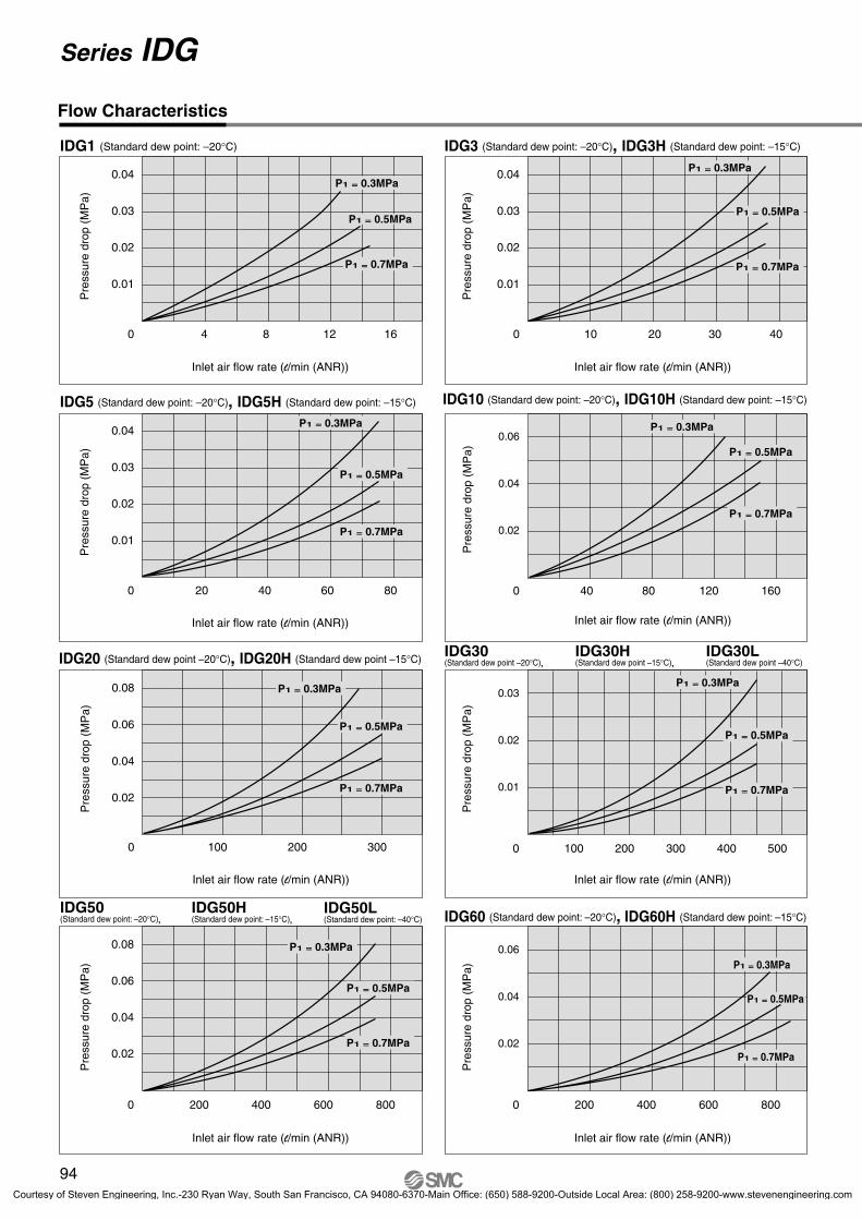
Conditions: Inlet air temperature 25°C, P1: Inlet air pressure
Courtesy of Steven Engineering, Inc.-230 Ryan Way, South San Francisco, CA 94080-6370-Main Office: (650) 588-9200-Outside Local Area: (800) 258-9200-www.stevenengineering.com
Conditions: Inlet air temperature 25°C
120
140
160
180
40
0
20
0.5
80
60
100
1.0
IDG50
IDG30
IDG50H
IDG50L
IDG30L
IDG30H
240
200
160
120
80
40
280
1.0
120
140
0 0.5
40
0
20
0.5
80
60
100
1.0
IDG100
IDG75
IDG60
IDG100H
IDG60H
IDG75H
40
50
60
1.00
10
20
30
0.5
IDG10
IDG20H
IDG20
IDG1IDG3H
IDG5IDG10H
IDG3,IDG5H
IDG60L
IDG75L
IDG100L
IDG75S
IDG100S
IDG60S
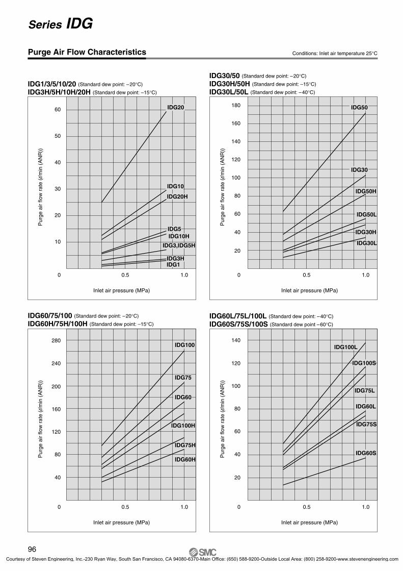
96
Series IDG
Purge Air Flow Characteristics
Pur
ge a
ir flo
w r
ate
(l/m
in (
AN
R))
IDG1/3/5/10/20 (Standard dew point: –20°C)
IDG3H/5H/10H/20H (Standard dew point: –15°C)
Inlet air pressure (MPa)
Pur
ge a
ir flo
w r
ate
(l/m
in (
AN
R))
Pur
ge a
ir flo
w r
ate
(l/m
in (
AN
R))
IDG60/75/100 (Standard dew point: –20°C)
IDG60H/75H/100H (Standard dew point: –15°C)
Inlet air pressure (MPa) Inlet air pressure (MPa)
IDG30/50 (Standard dew point: –20°C)
IDG30H/50H (Standard dew point: –15°C)
IDG30L/50L (Standard dew point: –40°C)
IDG60L/75L/100L (Standard dew point: –40°C)
IDG60S/75S/100S (Standard dew point –60°C)
Pur
ge a
ir flo
w r
ate
(l/m
in (
AN
R))
Inlet air pressure (MPa)
P0089-P0140-E.qxd 08.11.6 1:45 PM Page 96
Courtesy of Steven Engineering, Inc.-230 Ryan Way, South San Francisco, CA 94080-6370-Main Office: (650) 588-9200-Outside Local Area: (800) 258-9200-www.stevenengineering.com
97
AT
IDFA
IDFB
ID
IDG
AMG
AFF
AM
AMD
AMH
AME
AMF
SF
SFD
LLB
AD�
GD
HAAHAW
IDFIDU
P0089-P0140-E.qxd 08.11.6 1:45 PM Page 97
Courtesy of Steven Engineering, Inc.-230 Ryan Way, South San Francisco, CA 94080-6370-Main Office: (650) 588-9200-Outside Local Area: (800) 258-9200-www.stevenengineering.com
1
5
Size
102030506075
100
Flow rate by sizeOption
Port size
Accessory
NilSymbol
B
IDG 10
Single Unit/Standard Dew Point –20°C Specifications
01 1/802 1/403 3/8
SymbolType
BoreSize
1 5 10 20 30
04 1/2
3 50 60 75 100
NilPR
Symbol ContentsSize
1 5 10 20 30
S
3 50
Standard equipment
60 75 100
Note) In the case of two or more options, indicate them alphabetically.
Standard Specifications/Single Unit Type (Standard dew point: – 20°C)
ModelStandard dew point: –20°C
Fluid Compressed air
Inlet air temperature (°C) (1) –5 to 55Ambient temperature (°C) (1)
Inlet air temperature (°C)Inlet air saturation temperature (°C)Ambient temperature (°C)
BM65 IDG60, 75, 100∗ With cap bolts (2 pcs.) and spring washers (2 pcs.)
03
Outlet air flow ratePurge air flow rate
Note 1) No freezing.Note 2) ANR indicates the flow rate converted to the value at 20°C under the atmospheric pressure and the state of relative humidity 65%. Note 3) Includes 1 l /min (ANR) of purge air flow (at 0.7 MPa inlet air pressure) for the dew point indicator (except IDG1, 3, 5).
98
Symbol
Membrane Air Dryer
Series IDGHow to Order
Thread type
NilN F
RcNPT
G
None (Standard)With fitting for purge air dischargeFlow direction (Right → Left)With dew point indicator
DescriptionNone (Standard)
With bracket (Except IDG1)Note) When symbol B is indicated, a bracket
assembly with a part number shown in the table left below is included as an accessory.
Rang
e of o
pera
ting
cond
ition
s
Standardperfor-mance
Sta
ndar
d pe
rfor
man
ce c
ondi
tions
P0089-P0140-E.qxd 08.11.6 1:45 PM Page 98
Courtesy of Steven Engineering, Inc.-230 Ryan Way, South San Francisco, CA 94080-6370-Main Office: (650) 588-9200-Outside Local Area: (800) 258-9200-www.stevenengineering.com
–40
–30
–20
–10
0
4 8 12 160–40
–30
–20
–10
0
10 20 30 400
P1 = 0.3 MPa
P1 = 0.5 MPa
P1 = 0.7 MPa
–40
–30
–20
–10
0
0 40 80 120 160
P1 = 0.3 MPa
P1 = 0.5 MPa
P1 = 0.7 MPa
–50
–40
–30
–20
–10
0
0 200 400 600 800
–50
–40
–30
–20
–10
0
0 100 200 300 400 500
P1 = 0.3 MPa
P1 = 0.5 MPa
P1 = 0.7 MPa
P1 = 0.3 MPa
P1 = 0.5 MPa
P1 = 0.7 MPa
P1 = 0.3 MPa
P1 = 0.5 MPa
P1 = 0.7 MPa
–40
–30
–20
–10
0
20 40 60 800
P1 = 0.3 MPa
P1 = 0.5 MPa
P1 = 0.7 MPa
0–40
–30
–20
–10
0
100 200 300
P1 = 0.3 MPa
P1 = 0.5 MPa
P1 = 0.7 MPa
–500 200 400 600 800
–10
–40
–30
–20
0 P1 = 0.3 MPa
P1 = 0.5 MPa
P1 = 0.7 MPa
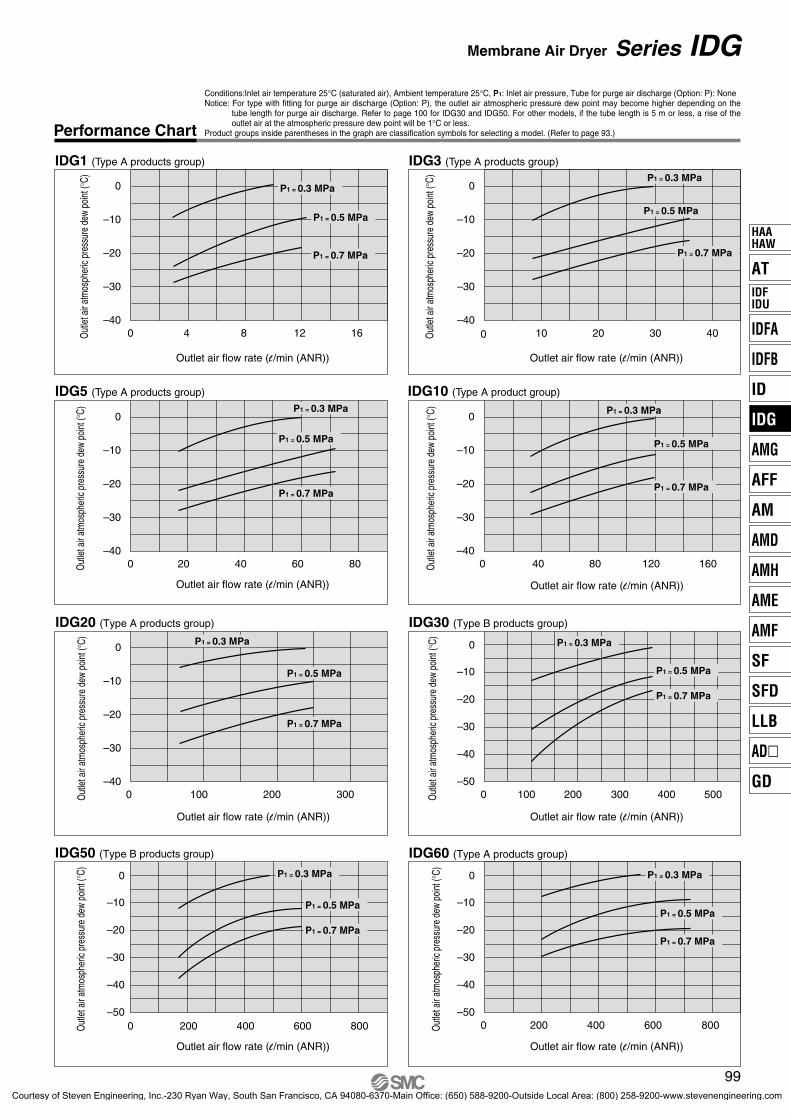
Conditions:Inlet air temperature 25°C (saturated air), Ambient temperature 25°C, P1: Inlet air pressure, Tube for purge air discharge (Option: P): NoneNotice: For type with fitting for purge air discharge (Option: P), the outlet air atmospheric pressure dew point may become higher depending on the
tube length for purge air discharge. Refer to page 100 for IDG30 and IDG50. For other models, if the tube length is 5 m or less, a rise of the outlet air at the atmospheric pressure dew point will be 1°C or less.
Product groups inside parentheses in the graph are classification symbols for selecting a model. (Refer to page 93.)
99
Membrane Air Dryer Series IDG
Performance Chart
IDG1 (Type A products group)
Outlet air flow rate (l /min (ANR))
Out
let a
ir at
mos
pher
ic pr
essu
re d
ew p
oint
(°C)
IDG10 (Type A product group)
IDG3 (Type A products group)
Outlet air flow rate (l /min (ANR))
Out
let a
ir at
mos
pher
ic pr
essu
re d
ew p
oint
(°C)
Outlet air flow rate (l /min (ANR))
Out
let a
ir at
mos
pher
ic pr
essu
re d
ew p
oint
(°C)
IDG60 (Type A products group)
Outlet air flow rate (l /min (ANR))
Out
let a
ir at
mos
pher
ic pr
essu
re d
ew p
oint
(°C)
IDG30 (Type B products group)
Outlet air flow rate (l /min (ANR))
Out
let a
ir at
mos
pher
ic pr
essu
re d
ew p
oint
(°C)
IDG5 (Type A products group)
Outlet air flow rate (l /min (ANR))
Out
let a
ir at
mos
pher
ic pr
essu
re d
ew p
oint
(°C)
IDG20 (Type A products group)
Outlet air flow rate (l /min (ANR))
Out
let a
ir at
mos
pher
ic pr
essu
re d
ew p
oint
(°C)
IDG50 (Type B products group)
Outlet air flow rate (l /min (ANR))
Out
let a
ir at
mos
pher
ic pr
essu
re d
ew p
oint
(°C)
AT
IDFA
IDFB
ID
IDG
AMG
AFF
AM
AMD
AMH
AME
AMF
SF
SFD
LLB
AD�
GD
HAAHAW
IDFIDU
P0089-P0140-E.qxd 08.11.6 1:45 PM Page 99
Courtesy of Steven Engineering, Inc.-230 Ryan Way, South San Francisco, CA 94080-6370-Main Office: (650) 588-9200-Outside Local Area: (800) 258-9200-www.stevenengineering.com
0 400 800 1200 1600–50
–40
–30
–20
–10
0 P1 = 0.3 MPa
P1 = 0.5 MPa
P1 = 0.7 MPa
–50
–40
–30
–20
–10
0
0 200 400 600 800 1000
P1 = 0.3 MPa
P1 = 0.5 MPa
P1 = 0.7 MPa
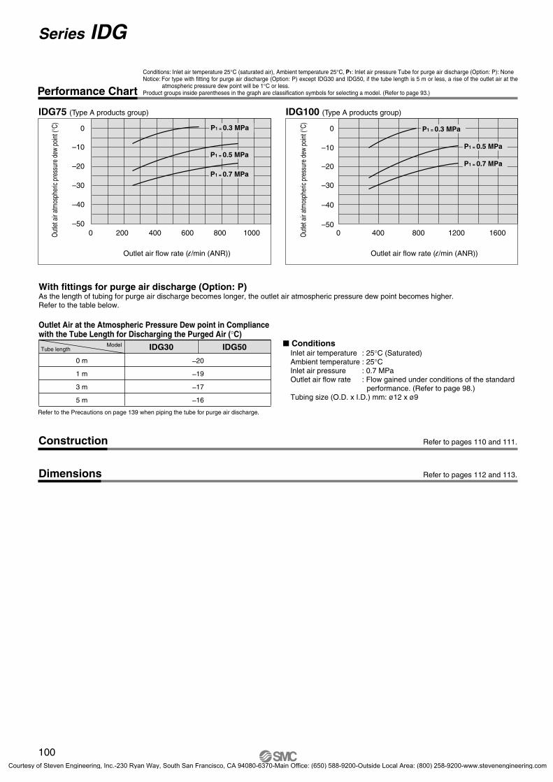
Conditions: Inlet air temperature 25°C (saturated air), Ambient temperature 25°C, P1: Inlet air pressure Tube for purge air discharge (Option: P): NoneNotice: For type with fitting for purge air discharge (Option: P) except IDG30 and IDG50, if the tube length is 5 m or less, a rise of the outlet air at the
atmospheric pressure dew point will be 1°C or less.Product groups inside parentheses in the graph are classification symbols for selecting a model. (Refer to page 93.)
100
Series IDG
Performance Chart
IDG100 (Type A products group)
Outlet air flow rate (l /min (ANR))
Out
let a
ir at
mos
pher
ic pr
essu
re d
ew p
oint
(°C)
IDG75 (Type A products group)
Outlet air flow rate (l /min (ANR))
Out
let a
ir at
mos
pher
ic pr
essu
re d
ew p
oint
(°C)
With fittings for purge air discharge (Option: P)As the length of tubing for purge air discharge becomes longer, the outlet air atmospheric pressure dew point becomes higher.Refer to the table below.
Tube lengthModel � Conditions
Inlet air temperature : 25°C (Saturated)Ambient temperature : 25°CInlet air pressure : 0.7 MPa Outlet air flow rate : Flow gained under conditions of the standard
performance. (Refer to page 98.) Tubing size (O.D. x I.D.) mm: ø12 x ø9
IDG30 IDG50
–20
–19
–17
–16
0 m
1 m
3 m
5 m
Outlet Air at the Atmospheric Pressure Dew point in Compliancewith the Tube Length for Discharging the Purged Air (°C)
Refer to the Precautions on page 139 when piping the tube for purge air discharge.
Refer to pages 110 and 111.Construction
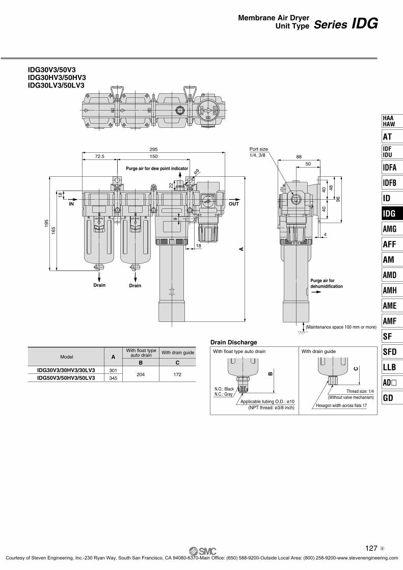
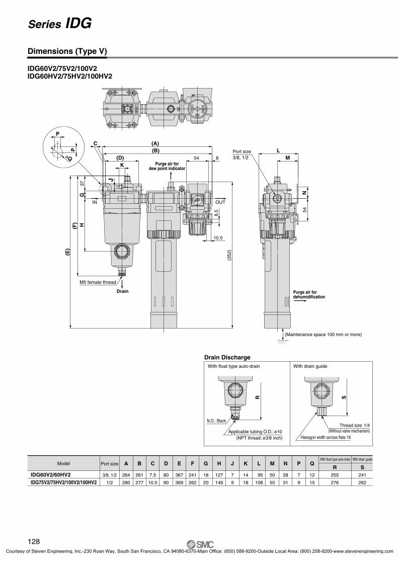
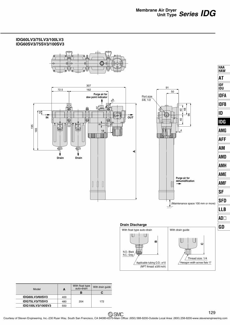
Refer to pages 112 and 113.Dimensions
P0089-P0140-E.qxd 08.11.6 1:45 PM Page 100
Courtesy of Steven Engineering, Inc.-230 Ryan Way, South San Francisco, CA 94080-6370-Main Office: (650) 588-9200-Outside Local Area: (800) 258-9200-www.stevenengineering.com
101
AT
IDFA
IDFB
ID
IDG
AMG
AFF
AM
AMD
AMH
AME
AMF
SF
SFD
LLB
AD�
GD
HAAHAW
IDFIDU
P0089-P0140-E.qxd 08.11.6 1:45 PM Page 101
Courtesy of Steven Engineering, Inc.-230 Ryan Way, South San Francisco, CA 94080-6370-Main Office: (650) 588-9200-Outside Local Area: (800) 258-9200-www.stevenengineering.com
Single Unit/Standard Dew Point –15°C Specifications
Bracket Assembly (Accessory) Part No.
Part no. Applicable model
BM59
BM61
BM63
BM64
IDG3H, 5H
IDG10H
IDG20H
IDG30H, 50H
BM65 IDG60H, 75H, 100H
Standard Specifications/Single Unit Type (Standard dew point: – 15°C)
1 l /min (ANR) {In the case of Inlet air pressure 0.7 MPa}
830 1110
50 100 200 300 500 600 750 1000
6 11 22 35 60 65 80 110
0.25(0.31)
0.43(0.51)
0.66(0.76)
0.74(0.87)
0.77(0.90)
1.50(1.65)
1.50(1.65)
1.55(1.70)
1/4, 3/81/8, 1/4 1/23/8, 1/2
Note 1) No freezing.Note 2) ANR indicates the flow rate converted to the value at 20°C under the atmospheric pressure and the state of relative humidity 65%. Note 3) Includes 1 l/min (ANR) of purge air flow (at 0.7 MPa inlet air pressure) for the dew point indicator (except IDG3H, 5H).
∗ With cap bolts (2 pcs.) and spring washers (2 pcs.)
IDG3H
IDG10H
IDG30HJIS Symbol
IDG3H
28
25
3
IDG 10 H
01 1/802 1/403 3/8
5 10 20 30
04 1/2
3 50 60 75 100
Nil None (Standard)With fitting for purge air dischargeFlow direction (Right → Left)With dew point indicator
PR
5 10 20 30
S
3 50
Standard equipment
60 75 100
Note) In the case of two or more options, indicate them alphabetically.
03
5102030506075
100
Flow rate by size
350/625/3
100/11200/22300/35500/60600/65750/80
1000/110
Sizel/min(ANR)
Outlet air flow ratePurge air flow rate
Option
Symbol Contents Size
Accessory
NilSymbol
B
Fluid
Inlet air temperature (°C) (1)
Ambient temperature (°C) (1)
Inlet air temperature (°C)Inlet air saturation temperature (°C)Ambient temperature (°C)
Outlet air atmosphericpressure dew point (°C)
Inlet air flow rate(l/min (ANR)) (2)
Outlet air flow rate(l/min (ANR))
Purge air flow rate(l/min (ANR)) (3)
Inlet air pressure(MPa)
Dew point indicator purge air flow rate
Port size (Nominal size B)
Mass (kg)(With bracket)
Inlet air pressure(MPa)
Type
102
Symbol
Series IDG
How to Order
Standard dew point temperatureSymbol
H
Standard dew point (°C)
–15
DescriptionNone (Standard)
With bracketNote) When symbol B is indicated, a bracket
assembly with a part number shown in the table left below is included as an accessory.
Port size
Symbol BoreSize
Rang
e of o
pera
ting
cond
ition
s
Standardperfor-mance
Sta
ndar
d pe
rfor
man
ce c
ondi
tions
Thread type
NilNF
RcNPT
G
P0089-P0140-E.qxd 08.11.6 1:45 PM Page 102
Courtesy of Steven Engineering, Inc.-230 Ryan Way, South San Francisco, CA 94080-6370-Main Office: (650) 588-9200-Outside Local Area: (800) 258-9200-www.stevenengineering.com
–50
–40
–30
–20
–10
0
0 200 400 600 1000800
P1 = 0.3 MPa
P1 = 0.5 MPa
P1 = 0.7 MPa
1000 200 300
–20
–10
0
–30
P1 = 0.3 MPa
P1 = 0.5 MPa
P1 = 0.7 MPa
–506000 200 400 800
–10
–40
–30
–20
0 P1 = 0.3 MPa
P1 = 0.5 MPa
P1 = 0.7 MPa
–40
–30
–20
–10
0
20 40 60 800
P1 = 0.3 MPa
P1 = 0.5 MPa
P1 = 0.7 MPa
–500 200 400 600 800
–10
–40
–30
–20
0 P1 = 0.3 MPa
P1 = 0.5 MPa
P1 = 0.7 MPa
–40
–30
–20
–10
0
0 40 80 120 160
P1 = 0.3 MPa
P1 = 0.5 MPa
P1 = 0.7 MPa
–50
–40
–30
–20
–10
0
0 100 200 300 400 500
P1 = 0.3 MPa
P1 = 0.5 MPa
P1 = 0.7 MPa
–40
–30
–20
–10
0
0 40302010
P1 = 0.3 MPa
P1 = 0.5 MPa
P1 = 0.7 MPa
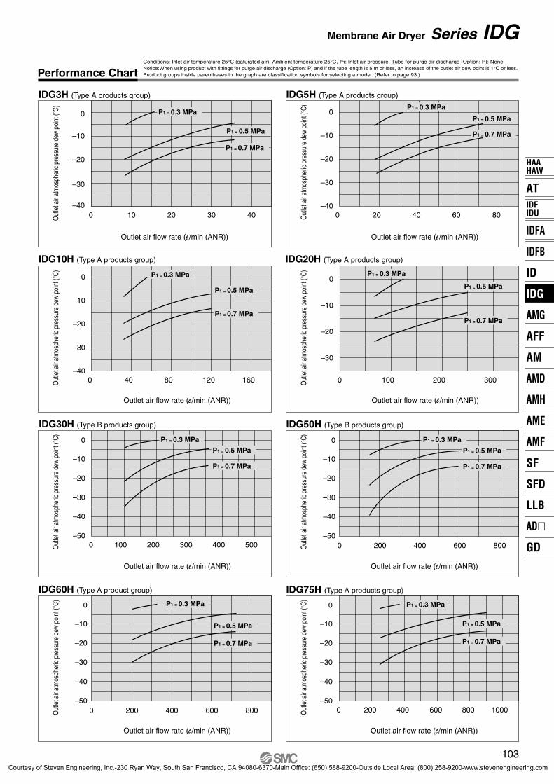
Conditions: Inlet air temperature 25°C (saturated air), Ambient temperature 25°C, P1: Inlet air pressure, Tube for purge air discharge (Option: P): NoneNotice:When using product with fittings for purge air discharge (Option: P) and if the tube length is 5 m or less, an increase of the outlet air dew point is 1°C or less.Product groups inside parentheses in the graph are classification symbols for selecting a model. (Refer to page 93.)
103
Membrane Air Dryer Series IDG
Performance Chart
IDG75H (Type A products group)
Outlet air flow rate (l /min (ANR))
Out
let a
ir at
mos
pher
ic pr
essu
re d
ew p
oint
(°C)
IDG60H (Type A product group)
Outlet air flow rate (l /min (ANR))
Out
let a
ir at
mos
pher
ic pr
essu
re d
ew p
oint
(°C)
IDG20H (Type A products group)
Outlet air flow rate (l /min (ANR))
Out
let a
ir at
mos
pher
ic pr
essu
re d
ew p
oint
(°C)
IDG10H (Type A products group)
Outlet air flow rate (l /min (ANR))
Out
let a
ir at
mos
pher
ic pr
essu
re d
ew p
oint
(°C)
IDG50H (Type B products group)
Outlet air flow rate (l /min (ANR))
Out
let a
ir at
mos
pher
ic pr
essu
re d
ew p
oint
(°C)
IDG30H (Type B products group)
Outlet air flow rate (l /min (ANR))
Out
let a
ir at
mos
pher
ic pr
essu
re d
ew p
oint
(°C)
IDG5H (Type A products group)
Outlet air flow rate (l /min (ANR))
Out
let a
ir at
mos
pher
ic pr
essu
re d
ew p
oint
(°C)
IDG3H (Type A products group)
Outlet air flow rate (l /min (ANR))
Out
let a
ir at
mos
pher
ic pr
essu
re d
ew p
oint
(°C)
AT
IDFA
IDFB
ID
IDG
AMG
AFF
AM
AMD
AMH
AME
AMF
SF
SFD
LLB
AD�
GD
HAAHAW
IDFIDU
P0089-P0140-E.qxd 08.11.6 1:45 PM Page 103
Courtesy of Steven Engineering, Inc.-230 Ryan Way, South San Francisco, CA 94080-6370-Main Office: (650) 588-9200-Outside Local Area: (800) 258-9200-www.stevenengineering.com
IDG100H (Type A products group)
–50
–40
–30
–20
–10
0
0 400 800 1200 1600
P1 = 0.3 MPa
P1 = 0.5 MPa
P1 = 0.7 MPa
Conditions: Inlet air temperature 25°C (saturated air), Ambient temperature 25°C, P1: Inlet air pressure, Tube for purge air discharge (Option: P): NoneNotice:When using product with fittings for purge air discharge (Option: P) and if the tube length is 5 m or less, an increase of the outlet air dew point is 1°C or less.Product groups inside parentheses in the graph are classification symbols for selecting a model. (Refer to page 93.)
104
Performance Chart
Series IDG
Refer to pages 110 and 111.Construction
Refer to pages 112 and 113.Dimensions
Outlet air flow rate (l /min (ANR))
Out
let a
ir at
mos
pher
ic pr
essu
re d
ew p
oint
(°C)
P0089-P0140-E.qxd 08.11.6 1:45 PM Page 104
Courtesy of Steven Engineering, Inc.-230 Ryan Way, South San Francisco, CA 94080-6370-Main Office: (650) 588-9200-Outside Local Area: (800) 258-9200-www.stevenengineering.com
105
AT
IDFA
IDFB
ID
IDG
AMG
AFF
AM
AMD
AMH
AME
AMF
SF
SFD
LLB
AD�
GD
HAAHAW
IDFIDU
P0089-P0140-E.qxd 08.11.6 1:45 PM Page 105
Courtesy of Steven Engineering, Inc.-230 Ryan Way, South San Francisco, CA 94080-6370-Main Office: (650) 588-9200-Outside Local Area: (800) 258-9200-www.stevenengineering.com
Single Unit/Standard Dew Point –40°C Specifications
Standard Specifications/Single Unit Type (Standard dew point: –40°C)
Standard dew point: –40°C
Compressed air
–5 to 50
0.3 to 1.0
–5 to 50
–40 (2)
IDG30L IDG50L IDG60L IDG75L IDG100L
100 150 227 320 400
0.7
252525
1 l /min (ANR) {In the case of Inlet air pressure 0.7 MPa}
75 110 170 240 300
25 40 57 80 100
0.74(0.87)
0.77(0.90)
1.50(1.65)
1.65(1.80)
1.80(1.95)
3/8, 1/21/4, 3/8
IDG30L
IDG60L
JIS Symbol
Bracket Assembly (Accessory) Part No.
Part no. Applicable model
BM64
BM65
IDG30L, 50L
IDG60L, 75L, 100L∗ With cap bolts (2 pcs.) and spring washers (2 pcs.)
Option
Port size
IDG 50 L
02 1/403 3/8
Symbol BoreSize
30
04 1/2
50 60 75 100
NilPR
03
30506075
100
75/25110/40170/57240/80300/100
Symbol Contents
Flow rate by size
Sizel/min(ANR)
Outlet air flow ratePurge air flow rate
Type
Accessory
NilSymbol
B
Model
Fluid
Inlet air temperature (°C) (1)
Ambient temperature (°C) (1)
Inlet air temperature (°C)Inlet air saturation temperature (°C)Ambient temperature (°C)
Outlet air atmosphericpressure dew point (°C)
Inlet air flow rate(l/min (ANR)) (3)
Outlet air flow rate(l/min (ANR))
Purge air flow rate(l/min (ANR)) (4)
Inlet air pressure(MPa)
Dew point indicator purge air flow rate
Port size (Nominal size B)
Mass (kg)(With bracket)
Inlet air pressure(MPa)
Note 1) No freezing.Note 2) Refer to the Piping Precautions (Piping material for low dew point air) on page 139. Note 3) ANR indicates the flow rate converted to the value at 20°C under the atmospheric pressure and the state of relative humidity 65%. Note 4) Includes 1 l /min (ANR) of purge air flow (at 0.7 MPa inlet air pressure) for the dew point indicator.
106
Symbol
Series IDG
How to Order
Standard dew point temperatureSymbol
L
Standard dew point (°C)
–40
Thread type
NilNF
RcNPT
G
None (Standard)With fitting for purge air discharge
Flow direction (Right → Left)
Note) In the case of two or more options, indicate them alphabetically.
DescriptionNone (Standard)
With bracketNote) When symbol B is indicated, a bracket
assembly with a part number shown in the table left below is included as an accessory.
Rang
e of o
pera
ting
cond
ition
s
Standardperfor-mance
Sta
ndar
d pe
rfor
man
ce c
ondi
tions
P0089-P0140-E.qxd 08.11.6 1:45 PM Page 106
Courtesy of Steven Engineering, Inc.-230 Ryan Way, South San Francisco, CA 94080-6370-Main Office: (650) 588-9200-Outside Local Area: (800) 258-9200-www.stevenengineering.com
0 20 40 60 80 100
–60
–50
–40
–30
–20
–10
0
–70
P1 = 0.3 MPa
P1 = 0.5 MPa
P1 = 0.7 MPa
–700
–60
–50
–40
–30
–20
–10
0
16040 80 120
P1 = 0.3 MPa
P1 = 0.5 MPa
P1 = 0.7 MPa
0 40 80 120 160 200
–60
–50
–40
–30
–20
–10
0
–70 –700
–60
–50
–40
–30
–20
–10
0
100 200 300
0 100 200 300 400
–60
–50
–40
–30
–20
–10
0
–70
P1 = 0.3 MPa
P1 = 0.5 MPa
P1 = 0.7 MPa
P1 = 0.3 MPa
P1 = 0.5 MPa
P1 = 0.7 MPa
P1 = 0.3 MPa
P1 = 0.5 MPa
P1 = 0.7 MPa
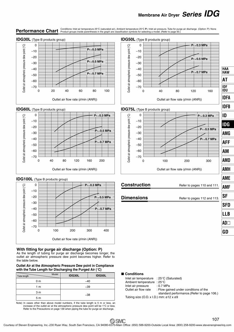
Note) In cases other than above model numbers, if the tube length is 5 m or less, an increase of the outlet air at the atmospheric pressure dew point will be 1°C or less. Refer to the Precautions on page 139 when piping the tube for purge air discharge.
Conditions: Inlet air temperature 25°C (saturated air), Ambient temperature 25°C P1: Inlet air pressure, Tube for purge air discharge (Option: P): None Product groups inside parentheses in the graph are classification symbols for selecting a model. (Refer to page 93.)
107
Membrane Air Dryer Series IDG
Performance Chart
IDG30L (Type B products group)
Outlet air flow rate (l/min (ANR))
Out
let a
ir at
mos
pher
ic pr
essu
re d
ew p
oint
(°C)
IDG50L (Type B products group)
Outlet air flow rate (l/min (ANR))
Out
let a
ir at
mos
pher
ic pr
essu
re d
ew p
oint
(°C)
IDG60L (Type B products group)
Outlet air flow rate (l/min (ANR))
Out
let a
ir at
mos
pher
ic pr
essu
re d
ew p
oint
(°C)
IDG75L (Type B products group)
Outlet air flow rate (l/min (ANR))
Out
let a
ir at
mos
pher
ic pr
essu
re d
ew p
oint
(°C)
IDG100L (Type B products group)
Outlet air flow rate (l/min (ANR))
Out
let a
ir at
mos
pher
ic pr
essu
re d
ew p
oint
(°C) Refer to pages 110 and 111.Construction
Refer to pages 112 and 113.Dimensions
Outlet Air at the Atmospheric Pressure Dew point in Compliancewith the Tube Length for Discharging the Purged Air (°C)
Tube lengthModel IDG30L IDG50L
–40
–39
–38
0 m
1 m
3 m
5 m
With fitting for purge air discharge (Option: P)As the length of tubing for purge air discharge becomes longer, the outlet air atmospheric pressure dew point becomes higher. Refer to the table below.
� ConditionsInlet air temperature : 25°C (Saturated)Ambient temperature : 25°CInlet air pressure : 0.7 MPaOutlet air flow rate : Flow gained under conditions of the
standard performance.(Refer to page 106.)Tubing size (O.D. x I.D.) mm: ø12 x ø9
AT
IDFA
IDFB
ID
IDG
AMG
AFF
AM
AMD
AMH
AME
AMF
SF
SFD
LLB
AD�
GD
HAAHAW
IDFIDU
P0089-P0140-E.qxd 08.11.6 1:45 PM Page 107
Courtesy of Steven Engineering, Inc.-230 Ryan Way, South San Francisco, CA 94080-6370-Main Office: (650) 588-9200-Outside Local Area: (800) 258-9200-www.stevenengineering.com
Bracket Assembly (Accessory) Part No.
Part no. Applicable model
BM65 IDG60S, 75S, 100S
Standard Specifications/Single Unit Type(Standard dew point: – 60°C)
Standard dew point: –60°C
Compressed air
–5 to 50
0.3 to 1.0
–5 to 50
–60 (2)
IDG60S IDG75S IDG100S
77 154 235
0.7
252525
1 l /min (ANR) {In the case of Inlet air pressure 0.7 MPa}
50 100 150
27 54 85
1.50(1.65)
1.65(1.80)
1.80(1.95)
3/8, 1/2
∗ With cap bolts (2 pcs.) and spring washers (2 pcs.)
IDG60S
Port size
IDG 60 S
03 3/804 1/2
60 75 100
6075
100
03 B
JIS Symbol
50/27
100/54150/85
Single Unit/Standard Dew Point –60°C Specifications
Flow rate by size
Sizel/min(ANR)
Outlet air flow ratePurge air flow rate
Type
Option
NilPR
Symbol Contents
Accessory
NilSymbol
B
Symbol BoreSize
Model
Fluid
Inlet air temperature (°C) (1)
Ambient temperature (°C) (1)
Inlet air temperature (°C)Inlet air saturation temperature (°C)Ambient temperature (°C)
Outlet air atmosphericpressure dew point (°C)
Inlet air flow rate(l/min (ANR)) (3)
Outlet air flow rate(l/min (ANR))
Purge air flow rate(l/min (ANR)) (4)
Inlet air pressure(MPa)
Dew point indicator purge air flow rate
Port size (Nominal size B)
Mass (kg)(With bracket)
Inlet air pressure(MPa)
Note 1) No freezing.Note 2) Refer to the Piping Precautions (Piping material for low dew point air) on page 139. Note 3) ANR indicates the flow rate converted to the value at 20°C under the atmospheric pressure and the state of relative humidity 65%. Note 4) Includes 1 l /min (ANR) of purge air flow (at 0.7 MPa inlet air pressure) for the dew point indicator.
108
Symbol
Series IDG
How to Order
Standard dew point temperatureSymbol
S
Standard dew point (°C)
–60
Thread type
NilNF
RcNPT
G
None (Standard)With fitting for purge air discharge
Flow direction (Right → Left)
Note) In the case of two or more options, indicate them alphabetically.
DescriptionNone (Standard)
With bracketNote) When symbol B is indicated, a bracket
assembly with a part number shown in the table left below is included as an accessory.
Rang
e of o
pera
ting
cond
ition
s
Standardperfor-mance
Sta
ndar
d pe
rfor
man
ce c
ondi
tions
P0089-P0140-E.qxd 08.11.6 1:45 PM Page 108
Courtesy of Steven Engineering, Inc.-230 Ryan Way, South San Francisco, CA 94080-6370-Main Office: (650) 588-9200-Outside Local Area: (800) 258-9200-www.stevenengineering.com
0
–60
–50
–40
–30
–20
–10
–70
20–80
0
40 60 80
P1 = 0.3 MPa
P1 = 0.5 MPa
P1 = 0.7 MPa
0
–60
–50
–40
–30
–20
–10
0
–70
–8040 80 120 160
P1 = 0.3 MPa
P1 = 0.5 MPa
P1 = 0.7 MPa
0 40
–60
–50
–40
–30
–20
–10
0
–70
–8080 120 160 200
P1 = 0.3 MPa
P1 = 0.5 MPa
P1 = 0.7 MPa
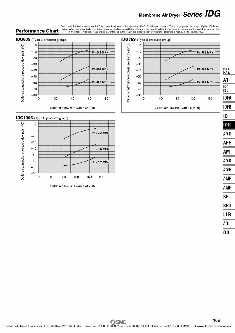
Conditions: Inlet air temperature 25°C (saturated air), Ambient temperature 25°C, P1: Inlet air pressure, Tube for purge air discharge (Option: P): NoneNotice: When using products with fitting for purge air discharge (Option: P) and if the tube length is 5 m or less, an increase of the outlet air dew point is
1°C or less. Product groups inside parentheses in the graph are classification symbols for selecting a model. (Refer to page 93.)
109
Membrane Air Dryer Series IDG
Performance Chart
IDG60S (Type B products group)
Outlet air flow rate (l/min (ANR))
Out
let a
ir at
mos
pher
ic p
ress
ure
dew
poi
nt (°
C)
IDG75S (Type B products group)
Outlet air flow rate (l/min (ANR))
Out
let a
ir at
mos
pher
ic p
ress
ure
dew
poi
nt (°
C)
IDG100S (Type B products group)
Outlet air flow rate (l/min (ANR))
Out
let a
ir at
mos
pher
ic p
ress
ure
dew
poi
nt (°
C)
AT
IDFA
IDFB
ID
IDG
AMG
AFF
AM
AMD
AMH
AME
AMF
SF
SFD
LLB
AD�
GD
HAAHAW
IDFIDU
P0089-P0140-E.qxd 08.11.6 1:45 PM Page 109
Courtesy of Steven Engineering, Inc.-230 Ryan Way, South San Francisco, CA 94080-6370-Main Office: (650) 588-9200-Outside Local Area: (800) 258-9200-www.stevenengineering.com
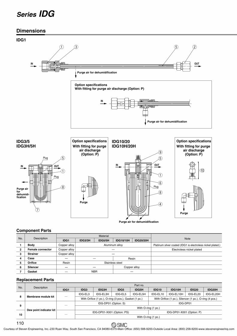
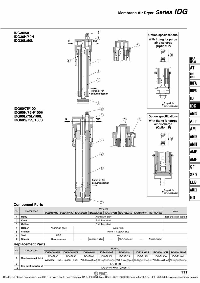
Replacement Parts
Component Parts
No.
1
2
3
4
5
6
7
Description
Body
Female connector
Strainer
Case
Orifice
Silencer
Gasket
Copper alloy
Copper alloy
Copper alloy
—
Resin
—
—
Aluminum alloy
—
—
Stainless steel
IDG1 IDG5/5H IDG10/10H IDG20/20H
Resin
Material
Platinum silver coated (IDG1 is electroless nickel plated.)
With Orifice (1 pc.), O-ring (3 pcs.), Gasket (1 pc.) With Orifice (1 pc.), Silencer (1 pc.), O-ring (4 pcs.)
With O-ring (1 pc.)
With O-ring (1 pc.)
IDG3
IDG-EL3
Part no.
IDG-EL3H IDG-EL5H IDG-EL10H IDG-EL20H
110
Option specificationsWith fitting for purge air discharge (Option: P)
Purge air for dehumidification
Purge air for dehumidification
Option specificationsWith fitting for purge
air discharge (Option: P)
Option specificationsWith fitting for purge
air discharge(Option: P)
IDG3/5IDG3H/5H
IDG10/20IDG10H/20H
Purge air for dehumidification
Purge
Purge
Purge airfordehumidi-fication
Plug
Plug
Plug
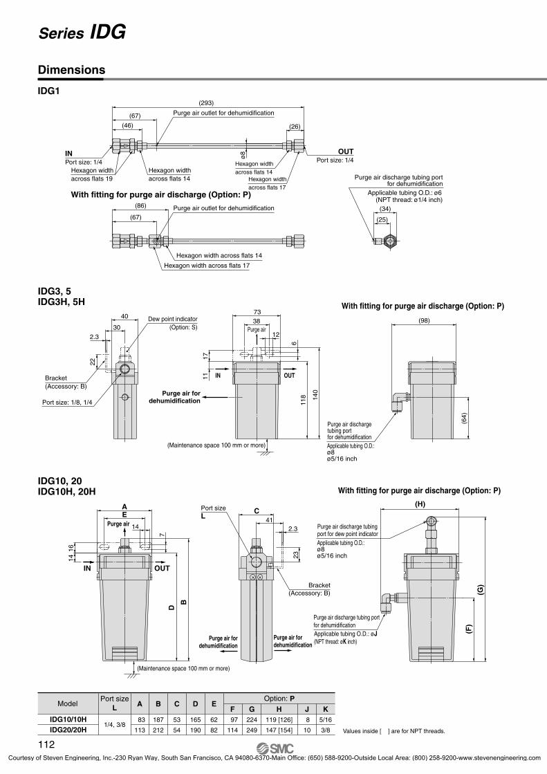
Series IDG
Dimensions
IDG1
P0089-P0140-E.qxd 08.11.6 1:45 PM Page 110
Courtesy of Steven Engineering, Inc.-230 Ryan Way, South San Francisco, CA 94080-6370-Main Office: (650) 588-9200-Outside Local Area: (800) 258-9200-www.stevenengineering.com
Courtesy of Steven Engineering, Inc.-230 Ryan Way, South San Francisco, CA 94080-6370-Main Office: (650) 588-9200-Outside Local Area: (800) 258-9200-www.stevenengineering.com
IDG3, 5IDG3H, 5H
IDG10, 20IDG10H, 20H
IN
1416
D
B
OUT
7
EA
(86)
(67)
(67)
(46) (26)
ø8
(34)
(25)
(293)
30
40
22
2.3
11
14
73
17
IN
38
2.3
2311
8 140
C41
6
12
OUT
(H)
(98)
(G)
(F)
(64)
IDG10/10HIDG20/20H Values inside [ ] are for NPT threads.
Model
1/4, 3/8
Option: PPort sizeL A B C D E
83 187 53 165 62
113 212 54 190 82
F G JH K 97 224 8119 [126] 5/16
114 249 10147 [154] 3/8
112
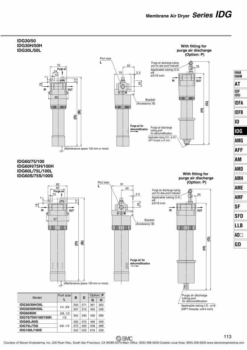
Series IDG
Dimensions
IDG1
Purge air outlet for dehumidification
Hexagon widthacross flats 19
INPort size: 1/4
OUTPort size: 1/4
Hexagon width across flats 14
Hexagon width across flats 14
Hexagon width across flats 17
With fitting for purge air discharge (Option: P)
Purge air outlet for dehumidification
Hexagon width across flats 14
Hexagon width across flats 17
Purge air discharge tubing portfor dehumidification
Applicable tubing O.D.: ø6(NPT thread: ø1/4 inch)
(Maintenance space 100 mm or more)
Purge air
Port size: 1/8, 1/4
Bracket(Accessory: B)
Purge air fordehumidification
Dew point indicator(Option: S)
With fitting for purge air discharge (Option: P)
Applicable tubing O.D.:ø8ø5/16 inch
Purge air discharge tubing portfor dehumidification
Purge air fordehumidification
(Maintenance space 100 mm or more)
Purge air
Port sizeL
With fitting for purge air discharge (Option: P)
Applicable tubing O.D.:ø8ø5/16 inch
Purge air discharge tubingport for dew point indicator
Courtesy of Steven Engineering, Inc.-230 Ryan Way, South San Francisco, CA 94080-6370-Main Office: (650) 588-9200-Outside Local Area: (800) 258-9200-www.stevenengineering.com
Courtesy of Steven Engineering, Inc.-230 Ryan Way, South San Francisco, CA 94080-6370-Main Office: (650) 588-9200-Outside Local Area: (800) 258-9200-www.stevenengineering.com
IDG30L/IDG50LIDG60 to IDG100IDG60H to IDG100HIDG60L to IDG100LIDG60S to IDG100SIDG3 to IDG50IDG3H to IDG50HIDG30L/IDG50LIDG60 to IDG100IDG60H to IDG100HIDG60L to IDG100LIDG60S to IDG100S Note) Not applicable with the cases of standard dew point –20°C (Nil), –15°C (symbol H).
∗ For the model selection of an auto-drain, refer to “Selection” 4 of Precautions on page 138.
∗ In the case of two or more options, indicate them alphabetically.Note 1) Type V is not applicable because it is equipped with a relief type regulator. (Symbol
P is used when it is undesirable for the air to be discharged into the main body of IDG. Therefore, it is not possible to use it in combination with a separator with man-ual valve, which discharges air around it, or Type V with a relief type regulator.)
Note 2) They are not applicable in case the thread type is N or F. (Because barrel nipples are used for equipment connections.)
• Drain discharge: Combi-nation with standard type (Nil) is not available.
• Combination with V type is not available. (1)
Auto drains listed on page 115 are attached.
Combination with Option P is not available.
Nil Standard
P
R
Symbol Contents Note5 10 20 30 50
S
60 75 100
Port size
01 1/802 1/403 3/8
5 10 20 30 50 60 75
Note)
100
04 1/2
3
Equipment connection: Models are applicable for either a modular connection or a nipple connection.
Note 1) For some of optional specification models, some parts may be connected with nipples (Refer to pages 121 and 122).Note 2) For some models, some parts may be connected with modules (Refer to page 128).
Note 1) Element service indicator is also available. Refer to “Made to Order Specifications” on page 131.
Note 2) Specifications with micro mist separator is also available. Refer to “Made to Order Specifications” on page 134.
Type
Nil
114
Symbol
Symbol
Symbol
Membrane Air DryerUnit Type
Series IDGHow to Order
Standarddew point
(°C)
Outlet air flow rate—Purge air flow rate
(l/min(ANR))Flow rate by size
Reg
ulat
or
Mem
bran
eai
r dr
yer
Mic
ro m
ist
sepa
rato
rw
ith p
re-f
ilter
Mic
ro m
ist
sepa
rato
r
Mis
tse
para
tor (2
)
(1)
Con
tent
s
Model
Description
With
sep
arat
orW
ith s
epar
ator
reg
ulat
or
With fitting forpurge air discharge
Flow direction (Right → Left)
With dew point indicator
Size
Standard equipment
(2) (2)(2)(2)
Manualvalve
N.C.auto-drain
N.O.auto-drain
Drain guide
( )Bore 1/4without valve
Symbol BoreSize
NilN F
RcNPT
G
P0089-P0140-E.qxd 08.11.6 1:45 PM Page 114
Courtesy of Steven Engineering, Inc.-230 Ryan Way, South San Francisco, CA 94080-6370-Main Office: (650) 588-9200-Outside Local Area: (800) 258-9200-www.stevenengineering.com
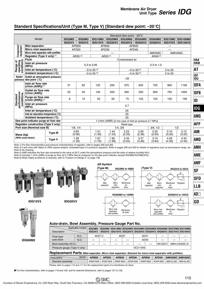
1 l /min (ANR) {In the case of Inlet air pressure 0.7 MPa}
900 1190725
50 100 200 300 500 600 750 1000
12 25 50 75 125 125 150 190
1.28(1.35)
1.67(1.76)
1.90(1.99)
3.34(3.45)
3.37(3.48)
3.74(3.84)
4.29(4.39)
4.34(4.44)
0.83(0.90)
1.21(1.30)
1.44(1.53)
2.23(2.33)
2.26(2.36)
2.55(2.65)
3.10(3.20)
3.15(3.25)
1/8, 1/4 1/4, 3/8 3/8, 1/2 1/2
Note 1) For flow characteristics and pressure characteristics of regulator, refer to pages 349 and 350. Note 2) It will come with Option E (With square-shaped, embedded type of a pressure regulator). Refer to pages 346 and 355 for details of regulators such as set pressure range, etc. Note 3) No freezing.Note 4) ANR indicates the flow rate converted to the value at 20°C under the atmospheric pressure and the state of relative humidity 65%.Note 5) Includes 1 l/min (ANR) of purge air flow (at 0.7 MPa inlet air pressure) for the dew point indicator (except IDG3M2/3V2/5M2/5V2).Note 6) When highly purified air is required, refer to “Caution on Design 2” on page 138.
IDG10V3
IDG60M2
IDG30V3
IDG3M3IDG3V3
31
25
6
Relief type
AFD40
AFD40P-060AS
AFM40
AFM40P-060AS
AMH450C
AMH-EL450
AMH350C
AMH-EL350
AFD30
AFD30P-060AS
AFM30
AFM30P-060AS
AFD20
AFD20P-060AS
AFM20
AFM20P-060AS
IDG3M3IDG3V3
AD27-C
—
—
—
—
(2) (2) (2)
Standard Specifications/Unit (Type M, Type V) [Standard dew point: –20°C]
115
Series IDGMembrane Air DryerUnit Type
Fluid
Micro mist separator Mist separator
Micro mist separator with prefilter
Inlet air temperature (°C)Ambient temperature (°C)
Inlet air temperature (°C)Inlet air saturation temperature (°C)Ambient temperature (°C)
Outlet air atmospheric pressuredew point (°C)Inlet air flow rate(l/min (ANR)) (4)
Outlet air flow rate(l/min (ANR))
Purge air flow rate(l/min (ANR)) (5)
Inlet air pressure(MPa)
Dew point indicator purge air flow rate
Port size (Nominal size B)
Type M
Type V
Inlet air pressure(MPa)
Ran
ge
of
op
erat
ing
con
dit
ion
sCo
mpo
nent
equi
pmen
t
Sta
nd
ard
p
erfo
rman
ce
con
dit
ion
s
Regulator (Type V only) (1)
Regulator construction (Type V only)
Mass (kg)(With auto-drain)
Standardperformance
Model
JIS Symbol(Type M) IDG3M3 to 50M3 IDG3V3 to 50V3
Mistseparator
Membraneair
dryer
Micromist
separator
IDG60M2 to 100M2
Micro mistseparator
with prefilter
Membraneair dryer
(Type V)
Mistseparator
Micromist
separator
RegulatorMembraneair
dryer
IDG60V2 to 100V2
Micro mist separator
with prefilter
RegulatorMembraneair
dryer
Auto-drain, Bowl Assembly, Pressure Gauge Part No.
Float typeauto-drain
Pressure gauge (Type V only)
Bowl assembly (N.O.)
Replacement Parts (Mist separator, Micro mist separator, Element for micro mist separator with prefilter)
Element assembly
Applicable models
Description
ModelDescription
For flow characteristics, refer to pages 119 and 120, and for external dimensions, refer to pages 121 to 129.
Please refer to pages 110 and 111 for the replacement parts of a membrane air dryer.
AT
IDFA
IDFB
ID
IDG
AMG
AFF
AM
AMD
AMH
AME
AMF
SF
SFD
LLB
AD�
GD
HAAHAW
IDFIDU
P0089-P0140-E.qxd 08.11.6 1:45 PM Page 115
Courtesy of Steven Engineering, Inc.-230 Ryan Way, South San Francisco, CA 94080-6370-Main Office: (650) 588-9200-Outside Local Area: (800) 258-9200-www.stevenengineering.com
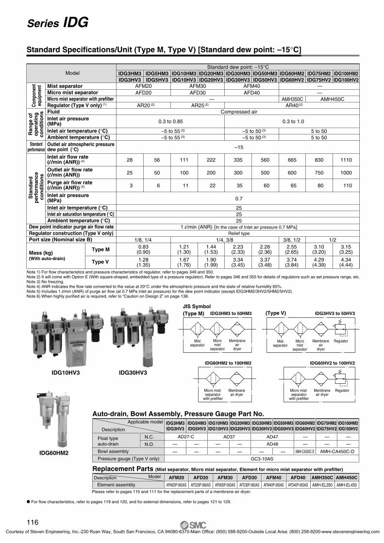
1 l /min (ANR) {In the case of Inlet air pressure 0.7 MPa}
830 1110665
50 100 200 300 500 600 750 1000
6 11 22 35 60 65 80 110
1.28(1.35)
1.67(1.76)
1.90(1.99)
3.34(3.45)
3.37(3.48)
3.74(3.84)
4.29(4.39)
4.34(4.44)
0.83(0.90)
1.21(1.30)
1.44(1.53)
2.23(2.33)
2.26(2.36)
2.55(2.65)
3.10(3.20)
3.15(3.25)
1/8, 1/4 1/4, 3/8 3/8, 1/2 1/2
IDG3HM3IDG3HV3
28
25
3
Relief type
IDG60HM2
(2) (2) (2)
Standard Specifications/Unit (Type M, Type V) [Standard dew point: –15°C]
Note 1) For flow characteristics and pressure characteristics of regulator, refer to pages 349 and 350. Note 2) It will come with Option E (With square-shaped, embedded type of a pressure regulator). Refer to pages 346 and 355 for details of regulators such as set pressure range, etc. Note 3) No freezing.Note 4) ANR indicates the flow rate converted to the value at 20°C under the atmospheric pressure and the state of relative humidity 65%.Note 5) Includes 1 l/min (ANR) of purge air flow (at 0.7 MPa inlet air pressure) for the dew point indicator (except IDG3HM2/3HV2/5HM2/5HV2).Note 6) When highly purified air is required, refer to “Caution on Design 2” on page 138.
116
Series IDG
Fluid
Micro mist separator Mist separator
Micro mist separator with prefilter
Inlet air temperature (°C)Ambient temperature (°C)
Inlet air temperature (°C)Inlet air saturation temperature (°C)Ambient temperature (°C)
Outlet air atmospheric pressuredew point (°C)Inlet air flow rate(l/min (ANR)) (4)
Outlet air flow rate(l/min (ANR))
Purge air flow rate(l/min (ANR)) (5)
Inlet air pressure(MPa)
Dew point indicator purge air flow rate
Port size (Nominal size B)
Type M
Type V
Inlet air pressure(MPa)
Ran
ge
of
op
erat
ing
con
dit
ion
sCo
mpo
nent
equi
pmen
t
Sta
nd
ard
p
erfo
rman
ce
con
dit
ion
s
Regulator (Type V only) (1)
Regulator construction (Type V only)
Mass (kg)(With auto-drain)
Standardperformance
Model
JIS Symbol(Type M) IDG3HM3 to 50HM3 IDG3HV3 to 50HV3
IDG60HM2 to 100HM2
(Type V)
IDG60HV2 to 100HV2
Mistseparator
Membraneair
dryer
Micromist
separator
Micro mist separator
with prefilter
Membraneair dryer
Mistseparator
Micromist
separator
RegulatorMembraneair
dryer
Micro mist separator
with prefilter
RegulatorMembraneair dryer
Auto-drain, Bowl Assembly, Pressure Gauge Part No.
Float typeauto-drain
Pressure gauge (Type V only)
Bowl assembly
Replacement Parts (Mist separator, Micro mist separator, Element for micro mist separator with prefilter)
Applicable model
Description
Element assembly
ModelDescription
For flow characteristics, refer to pages 119 and 120, and for external dimensions, refer to pages 121 to 129.
Please refer to pages 110 and 111 for the replacement parts of a membrane air dryer.
P0089-P0140-E.qxd 08.11.6 1:45 PM Page 116
Courtesy of Steven Engineering, Inc.-230 Ryan Way, South San Francisco, CA 94080-6370-Main Office: (650) 588-9200-Outside Local Area: (800) 258-9200-www.stevenengineering.com
1 l /min (ANR) {In the case of Inlet air pressure 0.7 MPa}
75 110 170 240 300
25 40 57 80 100
3.34(3.45)
3.37(3.48)
4.10(4.20)
4.25(4.35)
4.40(4.50)
2.23(2.33)
2.26(2.36)
2.99(3.09)
3.14(3.24)
3.29(3.39)
1/4, 3/8 3/8, 1/2
Note 1) For flow characteristics and pressure characteristics of regulator, refer to pages 349 and 350. Note 2) It will come with Option E (With square-shaped, embedded type of a pressure regulator). Refer to pages 346 and 355 for details of regulators such as set pressure range, etc. Note 3) No freezingNote 4) Refer to the Piping Precautions (Piping material for low dew point air) on page 139. Note 5) ANR indicates the flow rate converted to the value at 20°C under the atmospheric pressure and the state of relative humidity 65%. Note 6) Includes 1 l/min (ANR) of purge air flow (at 0.7 MPa inlet air pressure) for the dew point indicator.Note 7) When highly purified air is required, refer to “Caution on Design 2” on page 138.
Relief type
IDG30LV3
IDG60LV3 IDG60LM3
GC3-10AS
IDG30LM3IDG30LV3
IDG100LM3IDG100LV3
IDG75LM3IDG75LV3
IDG60LM3IDG60LV3
IDG50LM3IDG50LV3
AFD40
AFD40P-060AS
AFM40
AFM40P-060AS
AD47
AD48
N.C.
N.O.
(2)
(3)
(3)
Standard Specifications/Unit (Type M, Type V) [Standard dew point: –40°C]
Standard dew point: –40°C
117
Series IDGMembrane Air DryerUnit Type
Fluid
Micro mist separator Mist separator
Inlet air temperature (°C)Ambient temperature (°C)
Inlet air temperature (°C)Inlet air saturation temperature (°C)Ambient temperature (°C)
Outlet air atmospheric pressuredew point (°C)Inlet air flow rate(l/min (ANR)) (5)
Outlet air flow rate(l/min (ANR))
Purge air flow rate(l/min (ANR)) (6)
Inlet air pressure(MPa)
Dew point indicator purge air flow rate
Port size (Nominal size B)
Type M
Type V
Inlet air pressure(MPa)
Ran
ge
of
op
erat
ing
con
dit
ion
s
Componentequipment
Sta
nd
ard
p
erfo
rman
ce
con
dit
ion
s
Regulator (Type V only) (1)
Regulator construction (Type V only)
Mass (kg)(With auto-drain)
Standardperformance
Model
JIS Symbol(Type M)
Mistseparator
Micromist
separator
Membraneair
dryer
(Type V)
Mistseparator
Micromist
separator
RegulatorMembraneair dryer
Auto-drain, Pressure Gauge Part No.
Pressure gauge
Replacement Parts (Mist separator, Element for micro mist separator)
Element assembly
Applicable modelDescription
ModelDescription
Float typeauto-drain
Refer to pages 110 and 111 for the replacement parts of a membrane air dryer.
For flow characteristics, refer to pages 119 and 120 for external dimensions, refer to pages 123, 125, 127, and 129.
AT
IDFA
IDFB
ID
IDG
AMG
AFF
AM
AMD
AMH
AME
AMF
SF
SFD
LLB
AD�
GD
HAAHAW
IDFIDU
P0089-P0140-E.qxd 08.11.6 1:45 PM Page 117
Courtesy of Steven Engineering, Inc.-230 Ryan Way, South San Francisco, CA 94080-6370-Main Office: (650) 588-9200-Outside Local Area: (800) 258-9200-www.stevenengineering.com
GC3-10AS
IDG60SM3IDG60SV3
AD47
AD48
N.C.
N.O.
IDG100SM3IDG100SV3
IDG75SM3IDG75SV3
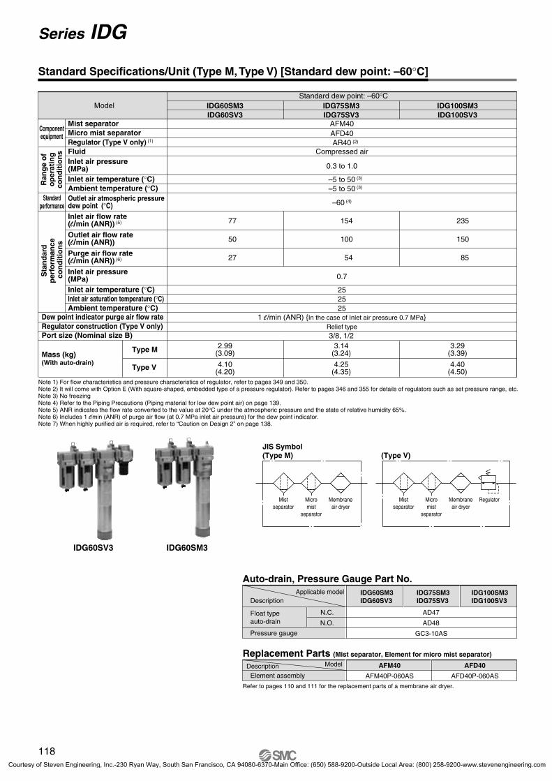
Standard dew point: –60°C
Compressed air
0.3 to 1.0
–5 to 50
–60 (4)
–5 to 50
IDG60SM3
AFM40AFD40AR40
IDG75SM3 IDG100SM3IDG60SV3 IDG75SV3 IDG100SV3
77 154 235
0.7
252525
1 l /min (ANR) {In the case of Inlet air pressure 0.7 MPa}
50 100 150
27 54 85
4.10(4.20)
4.25(4.35)
4.40(4.50)
2.99(3.09)
3.14(3.24)
3.29(3.39)
3/8, 1/2Relief type
AFD40
AFD40P-060AS
AFM40
AFM40P-060AS
IDG60SV3 IDG60SM3
(2)
Standard Specifications/Unit (Type M, Type V) [Standard dew point: –60°C]
Note 1) For flow characteristics and pressure characteristics of regulator, refer to pages 349 and 350. Note 2) It will come with Option E (With square-shaped, embedded type of a pressure regulator). Refer to pages 346 and 355 for details of regulators such as set pressure range, etc. Note 3) No freezingNote 4) Refer to the Piping Precautions (Piping material for low dew point air) on page 139. Note 5) ANR indicates the flow rate converted to the value at 20°C under the atmospheric pressure and the state of relative humidity 65%. Note 6) Includes 1 l/min (ANR) of purge air flow (at 0.7 MPa inlet air pressure) for the dew point indicator.Note 7) When highly purified air is required, refer to “Caution on Design 2” on page 138.
(3)
(3)
118
Series IDG
Fluid
Micro mist separator Mist separator
Inlet air temperature (°C)Ambient temperature (°C)
Inlet air temperature (°C)Inlet air saturation temperature (°C)Ambient temperature (°C)
Outlet air atmospheric pressuredew point (°C)Inlet air flow rate(l/min (ANR)) (5)
Outlet air flow rate(l/min (ANR))
Purge air flow rate(l/min (ANR)) (6)
Inlet air pressure(MPa)
Dew point indicator purge air flow rate
Port size (Nominal size B)
Type M
Type V
Inlet air pressure(MPa)
Ran
ge
of
op
erat
ing
con
dit
ion
s
Componentequipment
Sta
nd
ard
p
erfo
rman
ce
con
dit
ion
s
Regulator (Type V only) (1)
Regulator construction (Type V only)
Mass (kg)(With auto-drain)
Standardperformance
Model
JIS Symbol(Type M)
Mistseparator
Micromist
separator
Membraneair dryer
(Type V)
Mistseparator
Micromist
separator
RegulatorMembraneair dryer
Auto-drain, Pressure Gauge Part No.
Float typeauto-drain
Pressure gauge
Element assembly
Refer to pages 110 and 111 for the replacement parts of a membrane air dryer.
Applicable modelDescription
ModelDescription
Replacement Parts (Mist separator, Element for micro mist separator)
P0089-P0140-E.qxd 08.11.6 1:45 PM Page 118
Courtesy of Steven Engineering, Inc.-230 Ryan Way, South San Francisco, CA 94080-6370-Main Office: (650) 588-9200-Outside Local Area: (800) 258-9200-www.stevenengineering.com
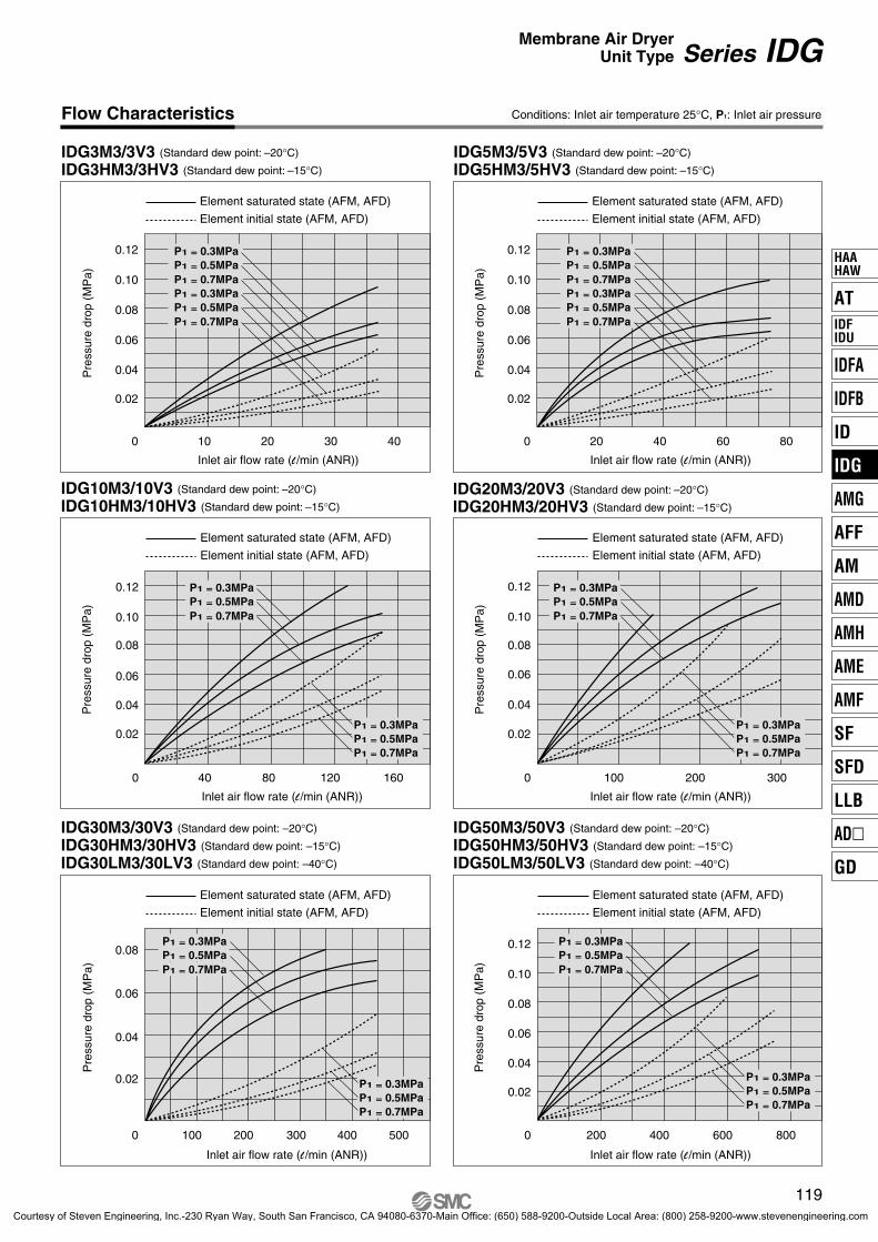
Conditions: Inlet air temperature 25°C, P1: Inlet air pressureFlow Characteristics
AT
IDFA
IDFB
ID
IDG
AMG
AFF
AM
AMD
AMH
AME
AMF
SF
SFD
LLB
AD�
GD
HAAHAW
IDFIDU
P0089-P0140-E.qxd 08.11.6 1:45 PM Page 119
Courtesy of Steven Engineering, Inc.-230 Ryan Way, South San Francisco, CA 94080-6370-Main Office: (650) 588-9200-Outside Local Area: (800) 258-9200-www.stevenengineering.com
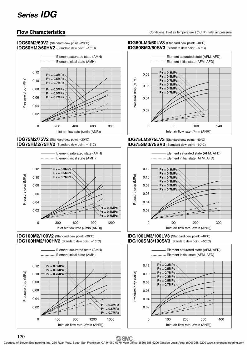
Inlet air flow rate (l /min (ANR)) Inlet air flow rate (l /min (ANR))
Pre
ssur
e dr
op (
MP
a)Inlet air flow rate (l /min (ANR))
Conditions: Inlet air temperature 25°C, P1: Inlet air pressureFlow Characteristics
P0089-P0140-E.qxd 08.11.6 1:45 PM Page 120
Courtesy of Steven Engineering, Inc.-230 Ryan Way, South San Francisco, CA 94080-6370-Main Office: (650) 588-9200-Outside Local Area: (800) 258-9200-www.stevenengineering.com
53
67
92924
24
30
3.2
115
M5 x 0.8
O S
SMC
SMC
SMC
116
97
10
118
43
12
5.5
ø5.541.5
159
140
OUTIN
O SO S
30
53
54
3.2
924
2924
67
SMC
SMC
SMC
10
12
ø5.5
134
115
118
5.5
(177
)
(64)
4341.5
M5 x 0.8M5 x 0.8
OUTIN
O SO S
121
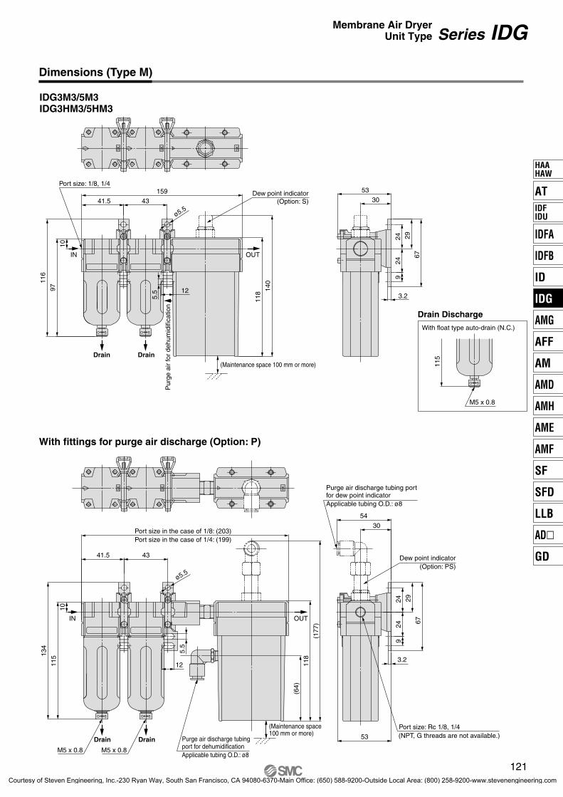
Series IDGMembrane Air DryerUnit Type
IDG3M3/5M3IDG3HM3/5HM3
Dimensions (Type M)
With fittings for purge air discharge (Option: P)
With float type auto-drain (N.C.)
Drain Discharge
Port size in the case of 1/8: (203)Port size in the case of 1/4: (199)
DrainDrain
Port size: 1/8, 1/4
(Maintenance space 100 mm or more)
Dew point indicator(Option: S)
Drain Drain Purge air discharge tubing port for dehumidification
Port size: Rc 1/8, 1/4(NPT, G threads are not available.)
Applicable tubing O.D.: ø8
Purge air discharge tubing portfor dew point indicatorApplicable tubing O.D.: ø8
Dew point indicator(Option: PS)
Pur
ge a
ir fo
r de
hum
idifi
catio
n
(Maintenance space100 mm or more)
AT
IDFA
IDFB
ID
IDG
AMG
AFF
AM
AMD
AMH
AME
AMF
SF
SFD
LLB
AD�
GD
HAAHAW
IDFIDU
P0089-P0140-E.qxd 08.11.6 1:45 PM Page 121
Courtesy of Steven Engineering, Inc.-230 Ryan Way, South San Francisco, CA 94080-6370-Main Office: (650) 588-9200-Outside Local Area: (800) 258-9200-www.stevenengineering.com
A B CD E
FG H
197
227
187
212
192
217
DE
170 136239
269
241
271
8
10
224
249
IDG10M3/10HM3IDG20M3/20HM3
82
41
3535
4
41
70
156
129
22
57
14
55
B
ø7
7
14
C
A
OUTIN
SMC
SMC
70
41
82
4135
(24)
35
4
SMC
SMC
(H)
(59)
197
14
9714
7
170
5755
ø7
(F)
OUTIN
SOS O
E
122
Series IDG
IDG10M3/20M3IDG10HM3/20HM3
Dimensions (Type M)
DrainDrain
(Maintenance space 100 mm or more)
(Maintenance space 100 mm or more)
Purge air fordew point indicator
Port size 1/4, 3/8
Purge airfor dehumidification
Purge airfor dehumidification
Purge air discharge tubing portfor dehumidificationApplicable tubing O.D. : øG
With fitting for purge air discharge (Option: P)
Port size : Rc 1/4, 3/8(NPT, G threads are not available.)
Purge air discharge tubing portfor dew point indicatorApplicable tubing O.D.: ø8
Drain Discharge
With drain guide
Rc 1/4(Without valve mechanism)
Drain Discharge
Model
Option: PWith float typeauto-drain
With drainguide
Portsize: 1/4
Portsize: 3/8
P0089-P0140-E.qxd 08.11.6 1:45 PM Page 122
Courtesy of Steven Engineering, Inc.-230 Ryan Way, South San Francisco, CA 94080-6370-Main Office: (650) 588-9200-Outside Local Area: (800) 258-9200-www.stevenengineering.com
With fitting for purge air discharge (Option: P)
D
C
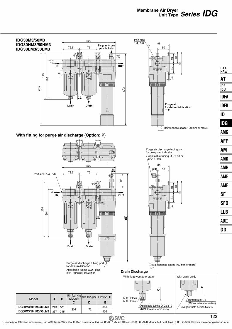
Model A BC D E
293
337
301
345204 172
361
405
IDG30M3/30HM3/30LM3IDG50M3/50HM3/50LM3
Option: PWith float typeauto-drain With drain guide
195
22
165
(B)
18
ø9
18
9
7572.5
220
(A)
OUTIN
4
96
48
4040
50
88
OUT
(24)88
50
4
48
96
4040
(Maintenance space 100 mm or more)
OUT
SMC
SMC
SMC
18
18
9
ø9
220
7572.5
234
204
18
(59)
(E)
DrainDrain
OUTIN
O SO S
ø70
123
Series IDGMembrane Air DryerUnit Type
IDG30M3/50M3IDG30HM3/50HM3IDG30LM3/50LM3
Drain Drain
Purge air for dewpoint indicator
Port size1/4, 3/8
(Maintenance space 100 mm or more)
Purge airfor dehumidification
Applicable tubing O.D.: ø8 orø5/16 inch
Purge air discharge tubing portfor dew point indicator
Courtesy of Steven Engineering, Inc.-230 Ryan Way, South San Francisco, CA 94080-6370-Main Office: (650) 588-9200-Outside Local Area: (800) 258-9200-www.stevenengineering.com
Purge air discharge tubing portfor dehumidification
With drain guide
With float type auto-drain
Drain Discharge
Hexagon width across flats 19
Thread size: 1/4(Without valve mechanism)
With float typeauto-drain
With drainguide
P0089-P0140-E.qxd 08.11.6 1:45 PM Page 124
Courtesy of Steven Engineering, Inc.-230 Ryan Way, South San Francisco, CA 94080-6370-Main Office: (650) 588-9200-Outside Local Area: (800) 258-9200-www.stevenengineering.com
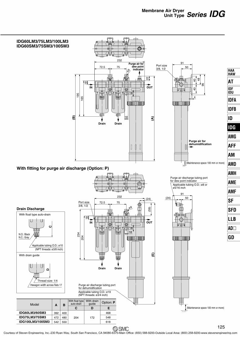
IDG60LM3/75LM3/100LM3IDG60SM3/75SM3/100SM3
With fitting for purge air discharge (Option: P)
DC
Model A BC D E
392
472
542
400
480
550
204 172
468
548
618
IDG60LM3/60SM3IDG75LM3/75SM3IDG100LM3/100SM3
195
165
(B)
18
18
9
22
ø9
232
7572.5
(A)
OUTIN
SMC
SMC
SMC
50
91
4
96
48
4040
OUT
SMC
SMC
SMC
(24)
18
9
ø9
234
204
18
232
7572.5
(59)
(E)
OUTIN
O S O S
(24)91
50
OUT
125
Series IDGMembrane Air DryerUnit Type
(Maintenance space 100 mm or more)
DrainDrain
DrainDrain
Purge air fordew pointindicator
Port size3/8, 1/2
Purge air fordehumidification
(Maintenance space 100 mm or more)
Applicable tubing O.D.: ø8 orø5/16 inch
Purge air discharge tubing portfor dew point indicator
Courtesy of Steven Engineering, Inc.-230 Ryan Way, South San Francisco, CA 94080-6370-Main Office: (650) 588-9200-Outside Local Area: (800) 258-9200-www.stevenengineering.com
Courtesy of Steven Engineering, Inc.-230 Ryan Way, South San Francisco, CA 94080-6370-Main Office: (650) 588-9200-Outside Local Area: (800) 258-9200-www.stevenengineering.com
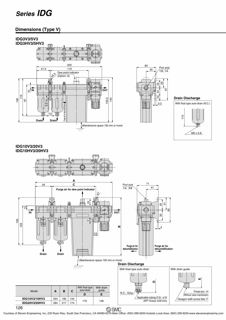
IDG30V3/50V3IDG30HV3/50HV3IDG30LV3/50LV3
IDG30V3/30HV3/30LV3IDG50V3/50HV3/50LV3
Model A
301
345
B C
204 172
C
B
4
96
48
4040
50
88
SMC
2O
UT1
I NSMC
SMC
22
195
18
ø9
A18
9
295
72.5 150
165
OUTIN
127
Series IDGMembrane Air DryerUnit Type
Purge air for dew point indicator
Purge air fordehumidificationDrain Drain
(Maintenance space 100 mm or more)
Port size1/4, 3/8
With float typeauto drain With drain guide With float type auto drain With drain guide
Courtesy of Steven Engineering, Inc.-230 Ryan Way, South San Francisco, CA 94080-6370-Main Office: (650) 588-9200-Outside Local Area: (800) 258-9200-www.stevenengineering.com
Hexagon width across flats 19(Without valve mechanism)
N.O.: Black
With float type auto-drain With drain guide
Dimensions (Type V)
P0089-P0140-E.qxd 08.11.6 1:45 PM Page 128
Courtesy of Steven Engineering, Inc.-230 Ryan Way, South San Francisco, CA 94080-6370-Main Office: (650) 588-9200-Outside Local Area: (800) 258-9200-www.stevenengineering.com
Courtesy of Steven Engineering, Inc.-230 Ryan Way, South San Francisco, CA 94080-6370-Main Office: (650) 588-9200-Outside Local Area: (800) 258-9200-www.stevenengineering.com
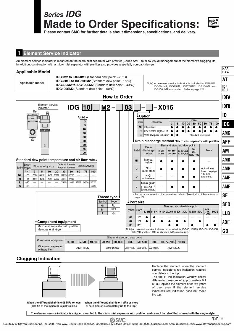
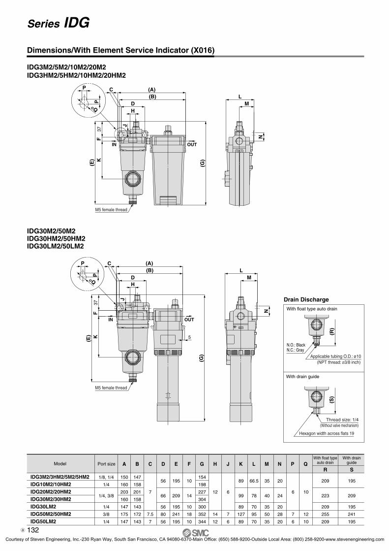
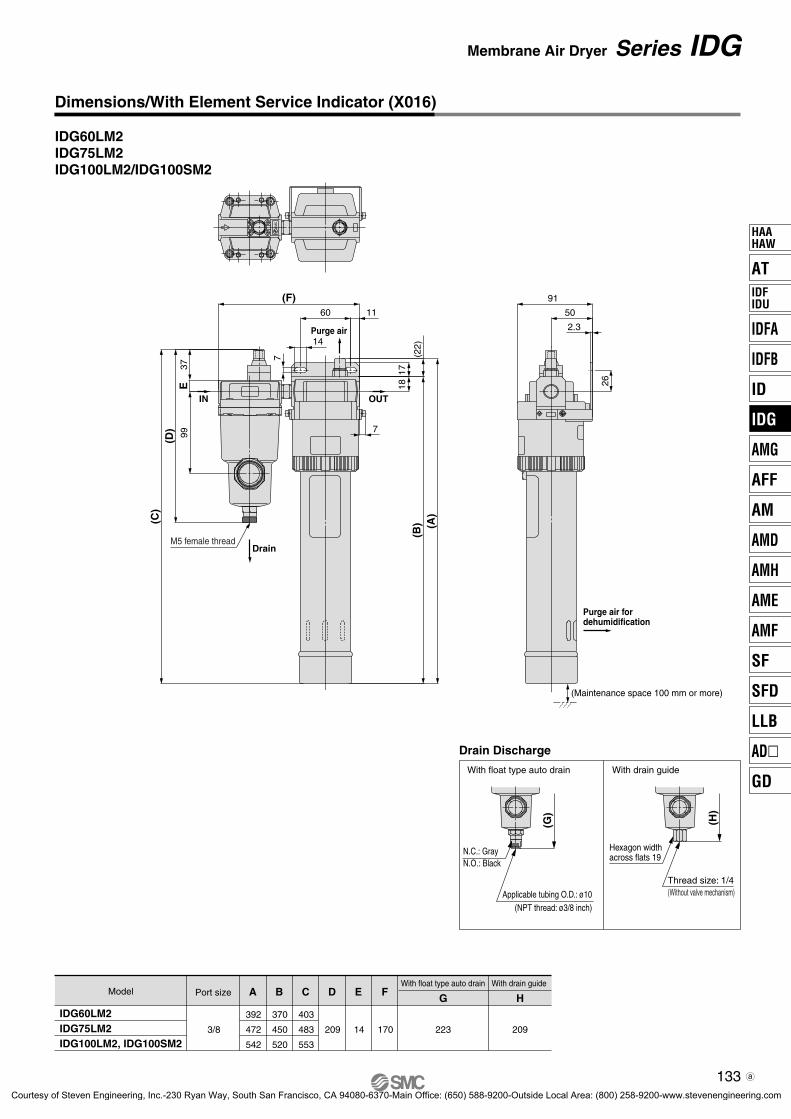
With micro mist separator (with element service indicator) with prefilter[Visual management of the element’s clogging and service life]
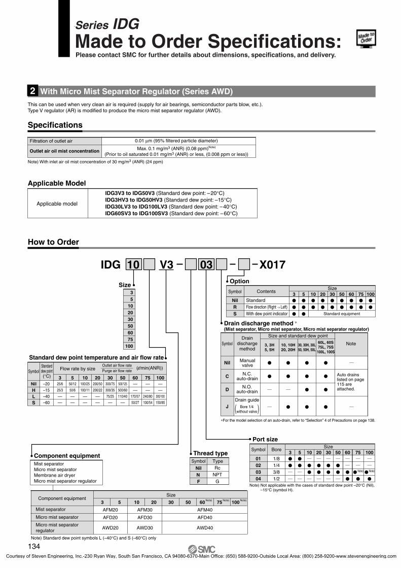
With micro mist separator regulator[Use when very clean air is required]
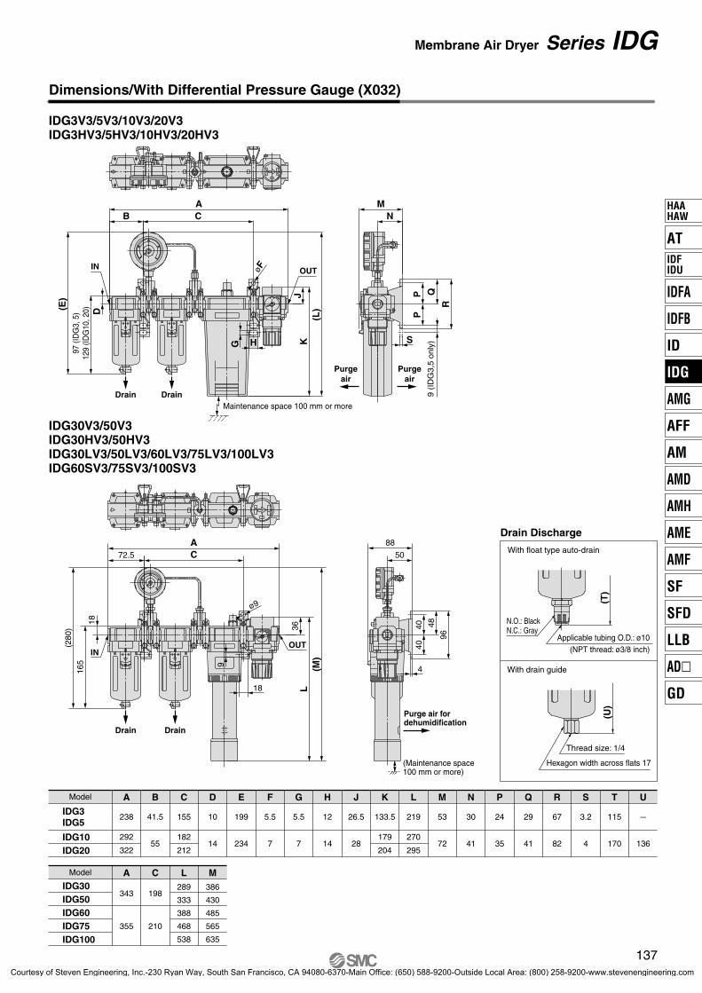
With differential pressure gauge[Control with differential pressure of the element’s clogging and service life]
DescriptionSymbol Page
X016
X017
X032
P.131
P.134
P.136
130
Series IDGMade to Order Specifications:Please contact SMC for further details about dimensions, specifications, and delivery.
P0089-P0140-E.qxd 08.11.6 1:45 PM Page 130
Courtesy of Steven Engineering, Inc.-230 Ryan Way, South San Francisco, CA 94080-6370-Main Office: (650) 588-9200-Outside Local Area: (800) 258-9200-www.stevenengineering.com
Size
IDG 10 M2
Component equipmentMicro mist separator with prefilterMembrane air dryer
Drain discharge method ∗Micro mist separator with prefilter
Option
Port size
How to Order
An element service indicator is mounted on the micro mist separator with prefilter (Series AMH) to allow visual management of the element’s clogging life.In addition, combination with a micro mist separator with prefilter also provides a spatially compact design.
Note) An element service indicator is included in IDG60M2, IDG60HM2, IDG75M2, IDG75HM2, IDG100M2 and IDG100HM2 as standard. Refer to page 124.
NilH
S
–20–15
–60
550/12
50/6
—
10100/25
100/11
—
20200/50
200/22
—
30300/75
300/35
—
50500/125
500/60
—
— — —— — —
60
—
75
—
100
150/85
325/6
25/3
—L –40 — — — 75/25 110/40 170/57 240/80 300/100—
∗ For the model selection of an auto-drain, refer to “Selection” 4 of Precautions on page 138.
C
D
J
3, 3H5, 5H
10, 10H20, 20H
30, 30H, 30L50, 50H, 50L
60L75L
100L, 100S
IDG3M2 to IDG50M2 (Standard dew point: –20°C)IDG3HM2 to IDG50HM2 (Standard dew point: –15°C)IDG30LM2 to IDG100LM2 (Standard dew point: –40°C)IDG100SM2 (Standard dew point: –60°C)
Element serviceindicator
Applicable Model
Applicable model
3
105
2030506075
100
03 X016
Thread type
Standard dew point temperature and air flow rate Nil
Symbol NoteDrain
dischargemethod
Size and standard dew point
Auto drains listed on page 115 are attached.
Type
131
Symbol
Symbol
Series IDGMade to Order Specifications:Please contact SMC for further details about dimensions, specifications, and delivery.
Standarddew point(°C)
Outlet air flow rate—Purge air flow rate
(l/min (ANR))Flow rate by size
StandardFlow direction (Right → Left)With dew point indicator
Contents
Manualvalve
N.C.auto-drain
N.O.auto-drain
Drain guide
( )Bore 1/4without valve
NilN F
RcNPT
G
Clogging Indication
When the differential air is 0.05 MPa or less(The tip of the indicator is just visible.)
When the differential air is 0.1 MPa or more(The indicator is completely up to the top.)
Replace the element when the element service indicator
,s red indication reaches
completely to the top.The top of the indication window shows differential pressure of approximately 0.1 MPa. Replace the element after two years of use, even if the element service indicator’s red indication does not reach the top.
The element service indicator is shipped mounted to the micro mist separator with prefilter, and cannot be retrofitted or used with the single style.
Note) An element service indicator is included in IDG60, IDG75, IDG100, IDG65H, IDG75H and IDG100H as standard (M2 specification).
AT
IDFA
IDFB
ID
IDG
AMG
AFF
AM
AMD
AMH
AME
AMF
SF
SFD
LLB
AD�
GD
HAAHAW
IDFIDU
5-2-11-IDG.qxd 09.9.30 5:44 PM Page 2
Courtesy of Steven Engineering, Inc.-230 Ryan Way, South San Francisco, CA 94080-6370-Main Office: (650) 588-9200-Outside Local Area: (800) 258-9200-www.stevenengineering.com
Courtesy of Steven Engineering, Inc.-230 Ryan Way, South San Francisco, CA 94080-6370-Main Office: (650) 588-9200-Outside Local Area: (800) 258-9200-www.stevenengineering.com
Courtesy of Steven Engineering, Inc.-230 Ryan Way, South San Francisco, CA 94080-6370-Main Office: (650) 588-9200-Outside Local Area: (800) 258-9200-www.stevenengineering.com
Note) Standard dew point symbols L (–40°C) and S (–60°C) only
Port size
IDG3V3 to IDG50V3 (Standard dew point: –20°C)IDG3HV3 to IDG50HV3 (Standard dew point: –15°C)IDG30LV3 to IDG100LV3 (Standard dew point: –40°C)IDG60SV3 to IDG100SV3 (Standard dew point: –60°C)
Applicable Model
Applicable model
This can be used when very clean air is required (supply for air bearings, semiconductor parts blow, etc.).Type V regulator (AR) is modified to produce the micro mist separator regulator (AWD).
With Micro Mist Separator Regulator (Series AWD) 2
Option
NilRS
SymbolSize
3 10 20 30 50 60 75 1005
Standard equipment
Specifications
3
105
2030506075
100
01 1/802 1/403 3/8
5 10 20 30 50 60 75 100
04 1/2
3
Nil
C
D
J
3, 3H5, 5H
10, 10H20, 20H
30, 30H, 30L50, 50H, 50L
60L, 60S75L, 75S
100L, 100S
NilH
S
–20–15
–60
550/12
50/6
—
10100/25
100/11
—
20200/50
200/22
—
30300/75
300/35
—
50500/125
500/60
—
—— —— — —
60
50/27
75
100/54
100
150/85
325/6
25/3
—L –40 — — — 75/25 110/40 170/57 240/80 300/100—
How to Order
Standard dew point temperature and air flow rate
Thread typeType
Symbol NoteDrain
dischargemethod
Size and standard dew point
∗For the model selection of an auto-drain, refer to “Selection” 4 of Precautions on page 138.
Auto drains listed on page 115 are attached.
Note) Not applicable with the cases of standard dew point –20°C (Nil), –15°C (symbol H).
Note) Note)
134
Symbol
Symbol
Series IDGMade to Order Specifications:Please contact SMC for further details about dimensions, specifications, and delivery.
Max. 0.1 mg/m3 (ANR) (0.08 ppm)Note)
(Prior to oil saturated 0.01 mg/m3 (ANR) or less, (0.008 ppm or less))
0.01 μm (95% filtered particle diameter)
Outlet air oil mist concentration
Filtration of outlet air
Note) With inlet air oil mist concentration of 30 mg/m3 (ANR) (24 ppm)
Standarddew point(°C)
Outlet air flow rate—Purge air flow rate
(l/min(ANR))Flow rate by size
Component equipment
Mist separator
Micro mist separator regulator
Micro mist separator
NilN F
RcNPT
G
StandardFlow direction (Right → Left)With dew point indicator
Contents
Manualvalve
N.C.auto-drain
N.O.auto-drain
Drain guide
( )Bore 1/4without valve
Symbol BoreSize
P0089-P0140-E.qxd 08.11.6 1:45 PM Page 134
Courtesy of Steven Engineering, Inc.-230 Ryan Way, South San Francisco, CA 94080-6370-Main Office: (650) 588-9200-Outside Local Area: (800) 258-9200-www.stevenengineering.com
Courtesy of Steven Engineering, Inc.-230 Ryan Way, South San Francisco, CA 94080-6370-Main Office: (650) 588-9200-Outside Local Area: (800) 258-9200-www.stevenengineering.com
IDG3V3 to IDG50V3 (Standard dew point: –20°C)IDG3HV3 to IDG50HV3 (Standard dew point: –15°C)IDG30LV3 to IDG100LV3 (Standard dew point: –40°C)IDG60SV3 to IDG100SV3 (Standard dew point: –60°C)
Applicable Model
Applicable model
The service life of the element service indicator can be controlled with differential pressure.
Note) For IDG60/75/100, standard dew point symbols L (–40°C) and S (–60°C) only.
3
105
2030506075
100
Auto drains listed on page 115 are attached.
C
Nil
D
J
3, 3H5, 5H
10, 10H20, 20H
30, 30H, 30L50, 50H, 50L
60L, 60S75L, 75S100L, 100S
01 1/802 1/403 3/8
5 10 20 30 50 60 75 100
04 1/2
3
How to Order
NilH
S
–20–15
–60
550/12
50/6
—
10100/25
100/11
—
20200/50
200/22
—
30300/75
300/35
—
50500/125
500/60
—
—— —— — —
60
50/27
75
100/54
100
150/85
325/6
25/3
—L –40 — — — 75/25 110/40 170/57 240/80 300/100—
Standard dew point temperature and air flow rate
Option
NilRS
SymbolSize
3 10 20 30 50 60 75 1005
Standard equipment
Symbol NoteDrain
dischargemethod
Size and standard dew point
∗ For the model selection of an auto-drain, refer to “Selection” 4 of Precautions on page 138.
Port size
Note) Not applicable with the cases of standard dew point –20°C (Nil), –15°C (symbol H).
Thread typeType
Mist separatorMicro mist separator Differential pressure gauge (GD40-2-01)Membrane air dryerRegulator
Note) Note)
136
Symbol
Symbol
Series IDGMade to Order Specifications:Please contact SMC for further details about dimensions, specifications, and delivery.
Standarddew point(°C)
Outlet air flow rate—Purge air flow rate
(l/min(ANR))Flow rate by size
StandardFlow direction (Right → Left)With dew point indicator
Contents
Manualvalve
N.C.auto-drain
N.O.auto-drain
Drain guide
( )Bore 1/4without valve
Symbol BoreSize
NilN F
RcNPT
G
Component equipment
Mist separator
Regulator
Micro mist separator
P0089-P0140-E.qxd 08.11.6 1:45 PM Page 136
Courtesy of Steven Engineering, Inc.-230 Ryan Way, South San Francisco, CA 94080-6370-Main Office: (650) 588-9200-Outside Local Area: (800) 258-9200-www.stevenengineering.com
Courtesy of Steven Engineering, Inc.-230 Ryan Way, South San Francisco, CA 94080-6370-Main Office: (650) 588-9200-Outside Local Area: (800) 258-9200-www.stevenengineering.com
138
Series IDGSpecific Product Precautions 1Be sure to read before handling. Refer to front matters 42 and 43 for Safety Instructions and pages 6 to 8 for Air Preparation Equipment Precautions.
Caution on Design
Warning
Caution
Selection
Mounting
Caution
1. Devise a layout which considers the position of purge air discharge ports.Purge air is humid air. Devise a layout in which purge air will not cause trouble such as corrosion or malfunction of peripheral equipment.
2. When very clean air is required(Supply to air bearings, blowing of semiconductor parts, etc.)Install a micro mist separator or super mist separator on the outlet side (end terminal) of the membrane air dryer (unit).Grease is applied inside a regulator used in the unit (V type). When air with high purity is required, please either mount the above separator on the outlet side or use a made-to-order product (refer to page 134), which is provided with a micro mist separator (Series AWD) instead of a regulator.
3. Time to reach the rated dew pointA certain amount of time is required to achieve the rated dew point after the air begins flowing into the membrane air dryer. Using the times below as a guide, begin operating outlet side equipment after the rated dew point is achieved.
Standard dew point –20°C, –15°C: about 10 min.Standard dew point –40°C : about 30 min. ∗Standard dew point –60°C : about 120 min. ∗
∗ This time can be shortened as described below. 1) Provide a valve on the outlet side of the membrane air
dryer. 2) Supply air with the valve closed. Only purge air flows into
the membrane air dryer.3) After 15 minutes or more, open the valve and let air flow
to the outlet side equipment.
4. Dehumidification performance when inlet air temperature changesDrying performance shows the case at an inlet air temperature of 25°C. In other cases, please refer to “Model Selection” (page 92) for proper selection.
1. Depending on the model and operating conditions, the oxygen ratio of the outlet air may drop below the prescribed standard.Do not use standard dew point –40°C (symbol L) type, standard dew point –60°C (symbol S) type and IDG30, 50, 30H, 50H for dehumidifying breathing air. Do not use only outlet air (dried air) in a closed room.
1. Consider the purge air flow rate.Find the purge air flow rate from the charts and calculate the “required outlet air flow rate + purge air flow rate”. The air supply capacity must be at least equal to the calculated flow or the required outlet air flow rate cannot be obtained.
2. Selection for a compressed air line in which a mist separator or micro mist separator is already installedVerify the operating air flow rate and air pressure, and select a membrane air dryer in accordance with the “Model Selection” section (page 92). If a membrane air dryer is selected using the port size of the equipment that is already installed as a reference, it could result in the selection of a model that is too small and has an insufficient dehumidification capacity.
3. With fittings for purge air discharge (Option: P)The dehumidification capacity decreases in proportion to the length of the tube for discharging purge air. Use a tube of the specified size and keep its length within 5 m. For the outlet air atmospheric pressure dew point in relation to the length of the tube for discharging purge air, refer to the table “Outlet Dew Point at Atmospheric Pressure to Tube for Exhaust of Purge Air” on page 107.
4. Auto-drain selection for the unit styleWhen the compressor in use is for 2.2 kW {300 l/min (ANR)} or less, please use an N.C. auto drain (symbol: C). If an N.O. auto drain (symbol: D) is used when the compressor is for 2.2 kW or less, pressure inside the mist separator may not increase and remain in the state of blowing off. Auto drain with differential pressure type can be used in 2.2 kW or less.
Caution1. Do not obstruct the purge air discharge ports.
If purge air back pressure becomes too high or purge air stops flowing, dehumidification performance will decrease or may become impossible.
2. Be sure to install a mist separator and micro mist separator or a micro mist separator with prefilter on the inlet side of the membrane air dryer.If the inlet air contains oil or water drops, etc., performance will be reduced. (A mist separator and micro mist separator or a micro mist separator with prefilter are already installed on the unit types.)
3. Large quantities of dust (solid foreign matter) or water droplets are contained in the supply air.• When there are large quantities of dust (solid foreign matter),
install an air filter or main line filter to the inlet side of the mist separator in addition to 2 above.
• When large quantities of water droplets are contained, install a water separator to the inlet side of the mist separator in addition to 2 above.
4. Install a regulator on the outlet side of the membrane air dryer.If it is installed on the inlet side, dehumidification performance will be reduced.
5. Take sufficient care in handling.There is a danger of damage if dropped.
P0089-P0140-E.qxd 08.11.6 1:45 PM Page 138
Courtesy of Steven Engineering, Inc.-230 Ryan Way, South San Francisco, CA 94080-6370-Main Office: (650) 588-9200-Outside Local Area: (800) 258-9200-www.stevenengineering.com
139
Piping
Warning Caution
Air Supply
Caution
Operating Environment
Caution
1. Confirm locking of case and body.When using in a unit, be sure to set the air pressure to zero before using a mist separator or micro mist separator with modular connections. Also, confirm that the body and case are locked together with a click before starting the flow of compressed air.
2. Confirm tightening of the holder. (for IDG30 to IDG100, IDG30H to IDG100H, IDG30L to
IDG100L and IDG60S to IDG100S) Before starting the flow of compressed air, turn the membrane air dryer's holder in its tightening direction, confirming that it is completely tightened and that the case will not come off.
3. Minimum bending radius (for IDG1)When installing piping for the membrane air dryer, maintain a minimum bending radius of 35 mm or more. Furthermore, do not bend the sections that are within 50 mm of the ends of the membrane module.
4. With fittings for purge air discharge (Option: P)
The piping of purge air for dehumidification and for the dew point checker can be combined, but do not combine it with compressed air lines or drain piping or merge the purge air with exhaust air from other equipment. As this can cause damage.
50
50
Min. bendingradius: 35
sectionscannot be bent.
1. Do not use at temperatures (fluid or ambient temperatures) higher than the prescribed operating conditions.Resin is used in the membrane module, and it can be damaged by operation at high temperatures. Especially when installed immediately after a reciprocating type air compressor, confirm that the fluid temperature does not exceed the range of operating conditions during use.
2. Keep the inlet air temperature lower than the ambient temperature.If the membrane air dryer
,s body is cooled by the surrounding
air, water drops may accumulate inside and reduce its dehumidification capacity.
1. Compressed air supply capacityAn air source that has a supply capacity that is larger than the “necessary outlet air flow rate (dry air flow rate) + purge air flow rate” is required. Verify the purge air flow rate in the Purge Air Flow Characteristics. (page 96)
1. Use of toolsHold the upper portion of the body (aluminum die-casted section) with a spanner or adjustable angle wrench. Do not turn it while holding the case section.
2. Drain piping for separatorsWhen installing drain piping for mist separators or micro mist separators, use a tube of the prescribed size and keep the length within 5 meters or less. Also, be sure that the tube does not rise up or become folded over.
3. Piping materials for low dew point airIf air of a low dew point (–40°C or less) is required, do not use a nylon tube piping and resin fittings (except fluoropolymer) for the outlet side of the membrane air dryer. Due to the nature of the nylon tube, it could be affected by the ambient air, and it might not be possible to achieve the prescribed low dew point at the end of the tube. Therefore, for low dew point air, use a stainless steel or fluoropolymer piping.
4. With fittings for purge air discharge (Option: P) (for IDG60 to IDG100, IDG60H to IDG100H, IDG60L to
IDG100L and IDG60S to IDG100S)To install piping for dehumidification purge air discharge, attach tubing of the prescribed size to the hose nipple section and then secure it with tubing bands.
Series IDGSpecific Product Precautions 2Be sure to read before handling. Refer to front matters 42 and 43 for Safety Instructions and pages 6 to 8 for Air Preparation Equipment Precautions.
AT
IDFA
IDFB
ID
IDG
AMG
AFF
AM
AMD
AMH
AME
AMF
SF
SFD
LLB
AD�
GD
HAAHAW
IDFIDU
P0089-P0140-E.qxd 08.11.6 1:45 PM Page 139
Courtesy of Steven Engineering, Inc.-230 Ryan Way, South San Francisco, CA 94080-6370-Main Office: (650) 588-9200-Outside Local Area: (800) 258-9200-www.stevenengineering.com
140
Maintenance
Warning
Caution
Caution
1. Confirming the dehumidification function with the dew point indicatorObserve the color of the dew point indicator to confirm whether the membrane air dryer is functioning normally.[When dew point indicator color is blue: Functioning normally] [When dew point indicator color is pink: Dew point tempera-ture is high. (Outlet air is humid.) Note: Atmospheric pressure dew point approximately –10°C minimum.]If humid air flowing in turns the color pink, and then if dry air enters, the color turns back to blue. It takes about 1 hour from the start of air flow for the dew point indicator color to change.
2. Dew point indicator replacement periodThe absorbent is used in the dew point indicator. It absorbs the gasified oil in the compressed air and/or the gaseous elements other than the air, and then may turn brown.When it turned brown, replace the dew point indicator. Besides, in the event of replacing them periodically, carry out after two-year operation as a guideline. (For the part number of the dew point indicator, refer to pages 110 and 111.)
3. Element replacement periodRefer to the following guide when replacing the elements in the mist separator and in the micro mist separator, or micro mist separator with prefilter that are installed on the inlet side of the membrane air dryer. 1) When two years have passed since installation. 2) When the unit’s pressure drop reaches 0.2 MPa, even be-
fore the two year period is reached. 3) When the red portion of the dew point indicator reaches
the upper limit. (With micro-mist separator with prefilter) [IDG60M to IDG100M, IDG60HM to IDG100HM, IDG60V to IDG100V, IDG60HV to IDG100HV] Note 1)
Note 1) For other models as well, they are available with the dew point indicator under made-to-order. Refer to page 131.
4. Membrane module replacement periodReplace the membrane module when the color of the dew point indicator turns white or pink. As a guideline, unit should be replaced after approximately 10 years of use (10 hours/day operation). Replace it when the color of the dew point indicator turns white or pink, even if it is within the period.
1. Do not remove the orifice (plug) when in a pressurized state. Never remove the orifice (plug) while under pressure, as it can fly out causing a hazard.
5. Tightening torque for installing the membrane module and the case(for IDG5/10/20/5H/10H/20H)Use caution not to tighten excessively.It may result in a breakdown of membrane module, case and mounting screws or insufficient sealing.(Verify the tightening torque range in the instruction manual.)
6. Installing a pressure gauge A pressure gauge should be installed on the inlet and outlet sides of the membrane air dryer (unit) for the maintenance and inspection purposes.
Series IDGSpecific Product Precautions 3Be sure to read before handling. Refer to front matters 42 and 43 for Safety Instructions and pages 6 to 8 for Air Preparation Equipment Precautions.
P0089-P0140-E.qxd 08.11.6 1:45 PM Page 140
Courtesy of Steven Engineering, Inc.-230 Ryan Way, South San Francisco, CA 94080-6370-Main Office: (650) 588-9200-Outside Local Area: (800) 258-9200-www.stevenengineering.com