Membrane and Electrode Materials for Alkaline Membrane Fuel Cells J. R. Varcoe, M. Beillard, D. M. Halepoto, J. P. Kizewski, S. D. Poynton, and R. C. T. Slade Division of Chemical Sciences, University of Surrey, Guildford, GU2 7XH, UK This paper and the associated presentation will describe the latest developments regarding alkaline anion–exchange membrane (AAEM) fuel cells at Surrey. The program of work conducted has been targeted at the materials development of both membranes and electrodes containing alkaline ionomers and as such has focused on H 2 /O 2 fuel cell testing. Radiation–grafted AAEMs can be made with fully hydrated thicknesses between 18 – 80 µm with conductivities in water of up to 0.06 S cm –2 at 60°C. A peak power density of 230 mW cm geo –2 and a maximum current density at full discharge of 1.3 A cm geo –2 have been obtained in a H 2 /O 2 fuel cell at 50°C with a 18 µm AAEM and Toray carbon paper based electrodes (Pt/C(20%mass), 0.5 mg Pt cm geo –2 loading) that were treated with Surrey’s first generation alkaline ionomer. A future priority is the development of the next generation alkaline ionomer. Introduction The vast majority of research into solid–state polymer electrolytes for low temperature fuel cells has focused on proton–exchange membranes (PEM), commonly Nafion ® by DuPont (USA), in proton–exchange membrane fuel cells (PEMFC). Recently, there has been increasing interest in the application of anion–exchange membranes (AEM), in alkaline–form, in low temperature fuel cells (1). Figure 1 compares the operation of fuel cells with these two types of ionic polymer electrolyte membranes. These alkaline anion– exchange membranes (AAEM) conduct negatively charged anions, including hydroxide (OH – ), rather than cations such as protons (H + ). Alkaline fuel cells (AFC), which traditionally utilize caustic aqueous potassium hydroxide (KOH) as a cheap electrolyte, are promising on a cost basis mainly because cheap and relatively abundant non– platinum–group–metals (non–PGM) are viable catalysts (the in situ durability of these catalysts is still be investigated). Catalyst electrokinetics (for fuel oxidation and oxygen reduction) is also improved in alkaline, as opposed to acidic, conditions (2). However, there are concerns that the presence of carbon dioxide (in the air supply or as a product of the oxidation of carbon–containing fuels) will lead to performance losses due to the formation in the aqueous alkaline electrolyte of less ionically conductive, and less basic, bicarbonate (HCO 3 – ) and carbonate (CO 3 2– ) anions (3). The replacement of the KOH(aq) electrolyte with an AAEM in AFCs (with elimination of metal cations) retains the electrocatalytic advantages but introduces CO 2 tolerance with the additional advantage of being an all solid state fuel cell (4). For example, it has been reported that Acta SpA (Italy) have developed non–PGM catalysts for alkaline membrane fuel cells (with reports of plans to make these fuel cell disposable when used with ethanol fuel) (5–7). Anion–exchange membranes are solid polymer
Transcript
Membrane and Electrode Materials for Alkaline Membrane Fuel Cells
J. R. Varcoe, M. Beillard, D. M. Halepoto, J. P. Kizewski, S. D. Poynton, and R. C. T. Slade
Division of Chemical Sciences, University of Surrey, Guildford, GU2 7XH, UK
This paper and the associated presentation will describe the latest developments regarding alkaline anion–exchange membrane (AAEM) fuel cells at Surrey. The program of work conducted has been targeted at the materials development of both membranes and electrodes containing alkaline ionomers and as such has focused on H2/O2 fuel cell testing. Radiation–grafted AAEMs can be made with fully hydrated thicknesses between 18 – 80 µm with conductivities in water of up to 0.06 S cm–2 at 60°C. A peak power density of 230 mW cmgeo
–2 and a maximum current density at full discharge of 1.3 A cmgeo
–2 have been obtained in a H2/O2 fuel cell at 50°C with a 18 µm AAEM and Toray carbon paper based electrodes (Pt/C(20%mass), 0.5 mgPt cmgeo
–2 loading) that were treated with Surrey’s first generation alkaline ionomer. A future priority is the development of the next generation alkaline ionomer.
Introduction
The vast majority of research into solid–state polymer electrolytes for low temperature fuel cells has focused on proton–exchange membranes (PEM), commonly Nafion® by DuPont (USA), in proton–exchange membrane fuel cells (PEMFC). Recently, there has been increasing interest in the application of anion–exchange membranes (AEM), in alkaline–form, in low temperature fuel cells (1). Figure 1 compares the operation of fuel cells with these two types of ionic polymer electrolyte membranes. These alkaline anion–exchange membranes (AAEM) conduct negatively charged anions, including hydroxide (OH–), rather than cations such as protons (H+). Alkaline fuel cells (AFC), which traditionally utilize caustic aqueous potassium hydroxide (KOH) as a cheap electrolyte, are promising on a cost basis mainly because cheap and relatively abundant non–platinum–group–metals (non–PGM) are viable catalysts (the in situ durability of these catalysts is still be investigated). Catalyst electrokinetics (for fuel oxidation and oxygen reduction) is also improved in alkaline, as opposed to acidic, conditions (2). However, there are concerns that the presence of carbon dioxide (in the air supply or as a product of the oxidation of carbon–containing fuels) will lead to performance losses due to the formation in the aqueous alkaline electrolyte of less ionically conductive, and less basic, bicarbonate (HCO3
–) and carbonate (CO32–) anions (3).
The replacement of the KOH(aq) electrolyte with an AAEM in AFCs (with
elimination of metal cations) retains the electrocatalytic advantages but introduces CO2 tolerance with the additional advantage of being an all solid state fuel cell (4). For example, it has been reported that Acta SpA (Italy) have developed non–PGM catalysts for alkaline membrane fuel cells (with reports of plans to make these fuel cell disposable when used with ethanol fuel) (5–7). Anion–exchange membranes are solid polymer
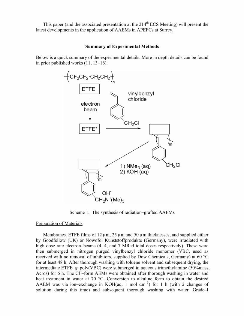
electrolyte membranes that contain positive ionic groups (typically quaternary ammonium groups: —N+Me3) and mobile negatively charged anions. Commercial AEMs are available from Solvay (Belgium – Morgane® ADP), Fumatech (Germany – FAA) and Tokuyama (Japan – typical fuel cell applicable examples being Neosepta® AHA and a new AAEM called A006) (8–10). Radiation–grafted AAEMs have been developed at Surrey (see Scheme 1) (11). This simple synthetic methodology allows for the fabrication of AAEMs, of different thicknesses and ion–exchange capacities, from preformed commercially available polymer films such as poly(ethylene–co–tetrafluoroethylene), ETFE, and therefore avoids the need for a film formation step. The aim was not to develop a commercial product, but to produce membranes that allowed for experiments to be conducted that would lead to fundamental insights into how AAEM properties and their performances in fuel cells are related.
Figure 1. A comparison of PEM and AAEM containing fuel cells
To allow for the AAEMs to be incorporated into alkaline membrane electrode assemblies (MEA) for alkaline polymer electrolyte fuel cells (APEFC) that contain no metal cations, it is essential to employ an alkaline ionomer analogue to the acidic Nafion® dispersions that are traditionally employed in PEMFCs (12). The incorporation of a first generation alkaline ionomer (Scheme 2) into a H2/O2 fuel cell operated at 50 °C containing Solvay’s ADP membrane led to an increased power density of 50 mW cmgeo
–2 compared to < 2 mW cmgeo
–2 for an alkaline–MEA containing no ionomer (all electrodes were identical and supplied by E–Tek (BASF) and contained Type–A carbon cloth gas diffusion layer and Pt in the catalyst layer and using a PTFE binder of proprietary loading). This clearly shows the need for an alkaline ionomer. As will be discussed in detail later, this first generation alkaline ionomer is not an optimal material for future commercial development (scaled–up production); however, it was developed with the intended purpose of allowing different AAEMs and electrodes to be tested in H2 fuel cells with acceptable performances and it achieved this initial aim well. For information, alkaline ionomer concepts from Fumatech and Tokuyama for use in fuel cells have recently been reported (9–10).
This paper (and the associated presentation at the 214th ECS Meeting) will present the latest developments in the application of AAEMs in APEFCs at Surrey.
Summary of Experimental Methods Below is a quick summary of the experimental details. More in depth details can be found in prior published works (11, 13–16).
Scheme 1. The synthesis of radiation–grafted AAEMs Preparation of Materials
Membranes. ETFE films of 12 µm, 25 µm and 50 µm thicknesses, and supplied either
by Goodfellow (UK) or Nowofol Kunststoffprodukte (Germany), were irradiated with high dose rate electron–beams (4, 4, and 7 MRad total doses respectively). These were then submerged in nitrogen purged vinylbenzyl chloride monomer (VBC, used as received with no removal of inhibitors, supplied by Dow Chemicals, Germany) at 60 °C for at least 48 h. After thorough washing with toluene solvent and subsequent drying, the intermediate ETFE–g–poly(VBC) were submerged in aqueous trimethylamine (50%mass, Acros) for 6 h. The Cl––form AEMs were obtained after thorough washing in water and heat treatment in water at 70 °C. Conversion to alkaline form to obtain the desired AAEM was via ion–exchange in KOH(aq, 1 mol dm–3) for 1 h (with 2 changes of solution during this time) and subsequent thorough washing with water. Grade–I
deionised water was used for all synthetic steps. Scheme 1 presents a graphical representation of the synthetic pathway and Table I presents the typical properties of the AAEMs produced (designated S20, S50 and S80 respectively).
TABLE I. Typical values for select properties of radiation–grafted AAEMs. AAEM Dry Thicknesses / µm Fully HydratedThicknesses / µm Ion–Exchange Capacity /
Electrodes. For the benchmark H2/O2 50 °C tests, prefabricated electrodes from E-
Tek (a division of BASF) were used for both the anode and the cathodes. These contained Pt/VulcanXC–72(20%mass) catalyst at 0.5 mgPt cmgeo
–2 loadings and were bound to one side of either Toray carbon paper or Type–A carbon cloth gas diffusion backing layers using PTFE binder (proprietary loadings). Before incorporation into MEAs for fuel cells, these prefabricated electrodes were sprayed with poly(vinylbenzyl chloride), dissolved in ethyl acetate, to get a typical loading of 0.5 mgpolymer cmgeo
–2 (13); these treated electrodes, after evaporation of the solvent in air, were then submerged in N,N,N',N'–tetramethylhexane–1,6–diamine (TMHDA, undiluted: caution – toxic), washed with water and then ion–exchanged in KOH(aq, 1 mol dm–3) as with the synthesis of the AAEMs. A schematic of the resulting alkaline ionomer (designated SION1) is shown below in Scheme 2.
Scheme 2. Surrey’s first generation alkaline ionomer (SION1)
Cathodes with alternative catalysts have also been tested and compared (all anodes consisted of the treated prefabricated carbon cloth electrodes described above) (16). These cathodes are synthesized by mixing the catalyst powders with poly(VBC) in ethyl acetate to form an ink and painting onto one side of a Toray carbon paper (TGPH–090) substrate; the cathodes are then treated with TMHDA and KOH(aq) as above. A typical loading of poly(VBC) of 0.7 mgpolymer cmgeo
–2 was used. The nature of the catalyst powders and their loadings are described in the main text where appropriate. Fuel Cell Testing
The AAEMs and SION1 treated electrodes were assembled in a 25 cm2 fuel cell fixture with a torque of 5.5 N m; prior hot–pressing to form a MEA was not conducted as the electrodes, once treated with SION1, do not laminate consistently. The H2/O2 fuel cell tests were conducted at 50 °C using an Arbin Fuel Cell Test Station (16); note this temperate was chosen for Surrey’s benchmark tests as SION1 starts to degrade at 60 °C and not because of the instability of the AAEMs, which are chemically stable in KOH(aq, 1 mol dm–3) up to 80 °C. The H2 and O2 gases were supplied to the anode and cathode respectively with dew points of 50 – 51 °C at flow rates of 2 dm3 min–1 (12 mmol(H2O) min–1 is being supplied to the cathode, which is enough water to support a current of 1.68 A cmgeo
–2 assuming no water is crossing over from the anode). The supply pipes between the dew point humidifiers and the fuel cell fixture were kept above the dew points to prevent premature condensation and loss of humidity control. Beginning of life cell voltage (Vcell / V) and geometric power density (P / mW cmgeo
–2) versus geometric current density (i / mA cmgeo
–2) plots were recorded from high current density to open circuit after a 2 – 3 h conditioning step where the fuel cell was discharged at high currents (by controlling the discharge at Vcell = 50 mV). The cell internal area resistances (r / Ω cmgeo
2) at each current density were obtained by measuring the high frequency impedance at a phase angle φ = 0° between the a.c. sinusoidal current and voltage signals using electrochemical impedance spectroscopy (EIS). The Solartron 1260/1287 combined electrochemical tests system was set to floating and was connected in parallel to the d.c. current loop running through the Arbin test system. This simple method is suitable at current densities below 1 A cmgeo
–2 but tends to overestimate the internal resistances at higher current densities; however, it is useful as the entire bandwidth of the impedance analyzer (1 MHz upper frequency limit in this case) can be used (13,16,17).
Results and Discussion AAEM Properties
Gravimetric water uptakes, WU = 100% × (mh – md) / md where mh = mass of the
fully hydrated AAEM and md = mass of the fully dehydrated AAEM, are typically in the range 35 – 55% for the radiation–grafted AAEMs. Table I presents the typical thicknesses and strong base ion–exchange capacities (IEC). Note: the e–beamed ETFE is grafted without pre–weighing as we have found this leads to slightly better reproducibility between batches of AAEM; IEC, as opposed to degree of grafting, is used as a fundamental characterization property of the membranes. There is generally a “sweet–spot” between IEC = 0.9 – 1.4 mmol(OH–) g–1(dry AAEM) where lower IECs lead to poor conductivities and higher IECs compromise physical integrity. An earlier
batch of S50 (data not shown), where the 25 µm base ETFE was e–beamed to 7 MRad (70 kGy) total dose, had a highly variable IEC (over the area of the AAEM batch) with an average of over 2 mmol g–1; this batch of S50 also exhibited pockets of water below the membrane surface along with some pitting. This problem was solved by lowering the total radiation dose to 4 MRad. It is not unexpected that the synthesis condition / AAEM property relationships will be a function of the membrane thickness. S20 synthesized by beaming 12 µm ETFE with a total dose of 4 MRad had an IEC of 2.25 mmol g–1 but this did not lead to formation of water pockets.
Figure 2. The ionic conductivities of select fully hydrated (submerged in liquid water) S80 (squares), S50 (circles) and Tokuyama Neosepta® AHA “ordinary” AAEM (triangles) as determined using 2–probe (through membrane) EIS.
The ionic conductivities of the fully hydrated AAEMs increase with temperature as expected. S80 consistently exhibits a higher conductivity compared to S50, which is unexpected as the similar chemistries should lead to similar conductivities. For third party verification, the in situ conductivity of a sample of S80 has been determined by Johnson Matthey; values around 0.06 S cm–1 at 60 °C were recorded. The conductivities of a commercially available AAEM sample, in this case Tokuyama’s Neosepta® AHA (230 µm thick and with fiber reinforcement), is also included for comparison. Measurements to determine the dependency of the conductivities on different synthesized S20 and S50 batches are ongoing (including S20 batches synthesized from a different supplier of ETFE). The ionic conductivities are lower when the AAEM is equilibrated in a relative humidity (RH) = 100% atmosphere rather than being submerged in water; for example, S80 has at conductivity at RH=100% and 30 °C of 0.022 S cm–1. Conductivities drop to unacceptable levels when the AAEMs are equilibrated at even lower RHs (14); this is due to the lower dissociation constant for –NMe3OH groups (requiring a higher
number of water molecules for complete dissociation) compared to –SO3H groups in PEMs, and a very low number of water molecules directly associated with the ionic groups (18,19); even at higher humidities, a lot of the water present in AAEMs is located in aggregates that are not directly associated with the ionic groups. DFT calculations, on model quaternary ammonium compounds, indicate that the stability of quaternary ammonium hydroxide groups is also lower when then membranes are not in the fully hydrated state (20). H2/O2 Fuel Cell Tests with Commercial E-Tek Prefabricated Pt/C Electrodes
The performances in fuel cells at 50 °C of S20, S50 and S80 with carbon paper electrodes are compared in Figure 3. A peak power density of 230 mW cmgeo
–2 was obtained with S20 at a current density of 600 mA cmgeo
–2 (Vcell = 382 mV). A current density of 290 mA cmgeo
–2 at a Vcell = 0.6 V (important operating efficiency lower limit) and 1.32 A cmgeo
–2 was obtained at full cell discharge. The move to using carbon paper gas diffusion layers for both the anodes and cathodes led to an increase in peak power densities compared to when carbon cloth based electrodes were used (Figure 4). Note: a proportion of the observed currents result from the carbon support material (16).
Figure 3. The performances of S80 (squares), S50 (triangles) and S20 (circles) obtained in H2/O2 fuel cells at 50 °C (2 dm3 min–1 fully hydrated gas flows and no back pressurization) with AAEMs of various fully hydrated thicknesses and Toray carbon paper based prefabricated E-Tek Pt/C(20%mass) 0.5 mgPt cmgeo
–2 loaded electrodes. All electrodes were treated with SION1 alkaline ionomer. Cell voltage data is represented by the filled symbols and power density data is represented by the hollow symbols.
The fuel cell reactions and standard potentials for H2/O2 fuel cells containing a AAEM (Equations 1 – 2) and a PEM (Equation 3 – 4) are compared below (assuming 4 e– oxygen reduction) [note: the sign of the reaction potentials, Eo, for anode reactions below are reversed as they are written as oxidation reactions]:
Anode: 2H2 + 4OH– → 4H2O + 4e– Eo = + 0.83 V vs. SHE (298.15 K) [1] Cathode: O2 + 2H2O + 4e– → 4OH– Eo = + 0.40 V vs. SHE (298.15 K) [2] Anode : 2H2 → 4H+ + 4e– Eo = 0.00 V vs. SHE (298.15 K) [3] Cathode: O2 + 4e– + 4H+ → 2H2O Eo = + 1.23 V vs. SHE (298.15 K) [4]
Figure 4. The peak power densities obtained in H2/O2 fuel cells at 50 °C with AAEMs of various fully hydrated thicknesses and either carbon cloth (squares) and carbon paper (diamonds) based prefabricated E-Tek Pt/C(20%mass) 0.5 mgPt cmgeo
–2 loaded electrodes. All electrodes were treated with SION1. The fuel cell test conditions were the same as described in the caption of Figure 3. The 153 µm thick membrane is Solvay’s Morgane® ADP membrane. The lines are guides to the eye only.
The performances increase on decreasing AAEM thicknesses; the current hypothesis is that crossover of water from the anode (where water is electro–generated) to the cathode (where water molecules are required to produce the OH– conductive ions on reaction with O2 gas molecules) is enhanced with the thinner AAEMs. A poor supply of reactant water to the cathode will manifest itself as an increased mass transport derived overpotential; mass transport losses in PEMs are normally associated with poor oxygen diffusion in the cathode, especially when flooding is occurring (water is electro–generated at the cathode for PEMs). The ir–corrected cell voltage data is presented in Figure 5 and this indicates that mass transport related voltages losses onset at higher current densities with S20. This is fully consistent with prior observations, which used
carbon cloth based anodes with both carbon cloth and carbon paper based cathodes (11,16). It is clear that the increased performance does not stem from changes in AAEM resistance. The cell resistance data indicates that the in situ area resistance of the S20 membrane is higher than the S50 AAEM; this is not expected when considering the IEC and low thickness of this membrane. The area resistance of the S50 AAEM is lower than expected compared to S80 when considering the conductivity data in Figure 2. Recall that the MEAs are not laminated: Variability in contact resistances will be significant.
Figure 6. The ir–corrected–Vcell and area resistance (r) versus log10(i) plots of S80 (squares), S50 (triangles) and S20 (circles) obtained in H2/O2 fuel cells at 50 °C. The test conditions were the same as described in the caption of Figure 3. Area resistance data is represented by the hollow symbols. Initial H2/O2 Fuel Cell Tests with Non–PGM cathodes
As mentioned in the introduction, non–PGMs can be used in AAEM–containing fuel cells. Most tests so far have reported to date have used Ag and Au catalysts at the cathodes (10, 13, 21–24). The electrokinetcis of the oxygen reduction reaction on a Ag nanocatalyst has been shown to be enhanced at the Ag|AAEM(s) interface compared to the Ag|NaOH(aq) interface with voltammetry experiments indicating different mechanisms were operating (25). MnO2 is well known to be active towards oxygen reduction in alkali (26) and has also been evaluated in a AAEM–based fuel cell (27). There is even a report on the use of a carbon–supported La1–xSrxMnO3 perovskite cathode catalyst (28).
Figure 7. The performances of Pt/C (squares), Au/C (triangles) and Ag/C (circles) cathodes obtained in H2/O2 fuel cells at 50 °C with S80 and carbon cloth based prefabricated E-Tek Pt/C(20%mass) 0.5 mgPt cmgeo
–2 loaded anodes. All cathode catalysts were E-Tek Metal/VulcanXC–72(20%mass) with loadings of 0.5 mgmetal cmgeo
–2. The fuel cell test conditions were the same as described in the caption of Figure 3. All electrodes were treated with SION1 alkaline ionomer.
Pt/C, Au/C and Ag/C cathode catalysts (all 20%mass using Vulcan XC–72 carbon supports and with 0.5 mgmetal cmgeo
–2 loadings) have been compared in equivalent H2/O2 fuel cells at 50 °C (same test conditions) and with Pt/C–based carbon cloth anodes (Figure 7 and Table II). The particle sizes of the metal particles are 3.11 ± 0.83 (n = 120), 4 – 100 nm (multidisperse and in vein form), and 30 – 60 nm (multidisperse) respectively (TEM). As expected, the Pt/XC–72 catalyst outperformed the non–Pt catalysts with peak power densities decreasing in the order Pt > Au > Ag. The internal ohmic resistances, electrokinetics and mass–transport losses all contributed to the above power density series (Figure 8). The above seemingly contradicts a previous study where peak power densities decreased in the order Pt ≈ Ag > Au (13); however, the Ag/C and Au/C cathodes used in this previous study contained metal/XC–72(60%mass) with loadings of 4 mgAg/Au cmgeo
–2 loadings compared to the Pt/C(20%mass)–containing cathode with a 0.5 mgPt cm–2 loading (the Pt Au and Ag particle sizes in this previous study were in the ranges 2 – 5 nm, 13 – 280 nm, and 200 – 2400 nm respectively). The need for future specific optimization of the catalyst powders for use in AAEM–based fuel cells is clear.
Table II also shows selected data from the H2/O2 fuel cell tests with cathode
containing Pt/C catalysts from two different suppliers and with two slightly different carbon supports (Vulcan XC72 and Vulcan XC–72R). HISPEC3000 (Johnson Matthey,
UK – containing Pt/VulcanXC–72R(20%mass)) with the Pt nanoparticles of particle sizes in the range 2 – 3 nm is a standard benchmark catalyst, which we have found to perform highly consistently in our fuel cell systems; previous studies using Solvay’s ADP AAEM with this catalyst show it to perform very well (16). It is immediately obvious that these Pt catalysts perform differently. More experiments are required to fully understand the source of these differences; the development of an alkaline ionomer, which allows for more consistent lamination of the MEA, is essential for acceptable comparisons. Note: the pseudo–Tafel slopes, b, should not be considered anything more than indicative; the first 4 low current density points only were used for the linear regression and no mass–transport corrections were applied. The in situ area resistances (EIS) for Pt/XC–72R (JM), Pt/XC–72R (E–Tek) and Pt/XC–72 (E–Tek) were recorded to be in the ranges 1.1 – 1.4, 1.4 – 1.5, 1.2 – 1.5 Ω cmgeo
2 respectively over the current densities tested: Changes in the onset of mass transport derived voltage losses were principally responsible for the differences in performances of these Pt–based catalysts (data not shown).
Figure 8. The ir–corrected–Vcell and area resistance (r) versus log10(i) plots of cathodes containing Pt/C (squares), Au/C (triangles) and Ag/C (circles) catalysts and obtained in H2/O2 fuel cells at 50 °C. The test conditions were the same as described in the caption of Figure 7.
TABLE II. Select fuel cell performance data of different cathode catalysts in H2/O2 fuel cells at 50 °C with S80 AAEM and identical Pt/C carbon cloth anodes. Catalyst suppliers: ET = E–Tek (BASF) and JM = Johnson Matthey.
S80 and S50 have been evaluated in direct methanol, ethanol and ethylene glycol fuel cells at 50 °C with no metal hydroxide added to the fuel supply (11, 15, 29). The preheated aqueous feeds (2 mol dm–3 alcohol) were supplied at 10 cm3 min–1 to the SION1 treated unsupported PtRu (4 mgmetal cmgeo
–2) containing E-Tek prefabricated carbon cloth anodes. These were used in conjunction with Pt black (4 mgPt cmgeo
–2) E-Tek prefabricated SION1 treated carbon cloth cathodes. The relevant cell reactions with methanol are shown in Equations 5 and 6 below. The complete oxidation of a methanol, ethanol or ethylene glycol molecule to CO2 yields 6, 12, and 10 electrons respectively. Anode: CH3OH + 6OH– → CO2 + 5H2O + 6e– Eo = + 0.81 V vs. SHE(298.15 K) [5] Cathode: 3/2O2 + 3H2O + 6e– → 6OH– Eo = + 0.40 V vs. SHE(298.15 K) [6] Peak power densities of 2.2 and 2,8 mW cmgeo
–2 were obtained with methanol for S80 and S50 respectively, even though the VOCV decreased from 0.57 to 0.48 V with increasing methanol crossover. The highest power density that could be obtained was 8.5 mW cmgeo
–2 when testing an early prototype S50 AAEM at 80 °C and with additional reactant pressurization (29); note SION1 ionomer was unstable over long periods of time at this temperature. Peak power densities of 2.1 and 2.0 mW cmgeo
–2 were obtained with ethanol and ethylene glycol respectively when using S80 (15). This class of AAEM exhibit low ex situ alcohol permeabilities, though this is likely to be due to the radiation–grafting nature of the membranes rather than being due specifically to the anion–exchange chemistry (15, 30); however, alcohol crossover should not be problematic with a properly engineered fuel cell where the alcohol concentration in the catalyst layer of the anode is designed to drop to nearly zero on electrooxidation. For comparison, Bunazawa and Yamazaki obtained power densities of nearly 8 mW cmgeo
–2 at 80 °C with non–alkaline methanol (aq, 1 mol dm–3) and no reported back pressurization using Tokuyama’s A006 AAEM and A3 alkaline ionomer combination (10).
Many other groups are investigating alcohol oxidation catalysts and fuel tolerant oxygen reduction catalysts for direct alcohol alkaline membrane fuel cells (eg. 5–7,21–24). Pd based anode catalysts appear promising for alcohol oxidation (31). Ethylene glycol is especially active towards electrooxidation in alkaline environments (21,22,32); ethylene glycol contains a C–C bond but, unlike with ethanol, the C/O ratio = 1 with each carbon atom bound to an oxygen atom. Most of these prior studies involved the addition of metal hydroxide to the alcohol fuel supply. Petrucco et al. (Johnson Matthey Technology Centre) have evaluated S80 in direct methanol fuel cells with additional KOH in the methanol supply (33). A peak power density of 50 mW cmgeo
–2 was obtained at 60 °C with the addition of KOH(aq, 1 mol dm–3), which was substantially higher than with alkali–free aqueous methanol fuel. The main contributor to this improved performance is an improved anode potential (300 mV reduction in anode overpotential). More investigations are required to probe the origins of this improvement. It could be due to: (a) reduced pH at the anode (compared to the cathode) resulting from carbonate formation in the active layers on reaction of the CO2 product of methanol oxidation with the OH– anions generated at the cathode, yielding a negative pH gradient from the cathode to the anode (34); and/or (b) inadequate supply of OH– anions to the methanol oxidation sites (see Equation 5: 6 × OH– anions are required converge on a single catalytic site to oxidize 1 × CH3OH molecule – this is quite a challenge!) (22).
The Need for a New Alkaline Ionomer
Figure 9. The EDX spectrum of an E–Tek carbon cloth Pt/C(20%mass) electrode with a loading of 0.5 mgPt cmgeo
–2 that was coated (on the catalyst layer) with 0.5 mg cmgeo–2
poly(vinylbenzyl chloride) and immersed in N,N,N',N'–tetramethyhexane–1,6–diamine for 24 h, followed by ion–exchange to the OH– form.
The tests above show that SION1 allows for effective testing of different AAEMs and catalysts in alkaline membrane containing fuel cells, which was the primary objective when it was being developed. However, as alluded to earlier, this alkaline ionomer concept is non–ideal is several respects: (a) It required the poly(vinylbenzyl chloride) to be deposited using an organic solvent onto highly flammable catalytic powders, which would present an unacceptable hazard on scale-up; (b) The application of SION1 inhibited satisfactory MEA lamination; (c) The poly(VBC) treated electrodes have to be submerged in toxic N,N,N',N'–tetramethyhexane–1,6–diamine, which would create a large volume of chemical waste; (d) The ionomer contains β–hydrogen atoms therefore allowing the Hofmann elimination degradation mechanism to operate and limiting the thermal stability to below 60 °C; (e) Analysis of the SION1 treated electrodes indicate that not all of the benzyl chloride groups of the poly(VBC) polymer react with the diamine (see Figure 9); and (f) The poly(VBC) soaks through to the gas diffusion layer of the carbon cloth electrodes (see Figure 10) resulting in non–ideal gas/water diffusion characteristics (this is less of a problem with the carbon paper electrodes).
To address the issues raised above, Surrey is developing the next–generation of
alkaline ionomer specifically for use in alkaline membrane fuel cells up to temperatures of 80 °C (SION2). This ionomer: (a) is deposited onto electrode from aqueous solutions reducing the fire hazard; (b) the ionomer is deposited in an anionic form and so does not require a quaternisation step and therefore immersion of the elecrtode in toxic substances; and (c) contains no β–hydrogen atoms for improved thermochemical stability. Details on this alkaline ionomer will be published in due course after IP protection is completed.
Figure 10. Scanning Electron Micrographs of the gas diffusion layer of an E–Tek Type–A carbon cloth electrode with before (left) and after (right) poly(vinylbenzyl chloride) and N,N,N',N'–tetramethyhexane–1,6–diamine (SION1) treatment.
Concluding Remarks
The materials developments discussed in this paper demonstrate that there are no fundamental barriers to the application of alkaline anion–exchange membranes (AAEM) in low temperature fuel cells, contrary to prevailing wisdom as recently as 5 year ago. Benzyltrimethylammonium containing AAEMs have thermochemical stabilities up to 80 °C and conductivities above 0.06 S cm-1 at 60 °C are achievable (when fully hydrated). Recent progress at Surrey is highlighted by the following chronological advancements in peak power densities in metal–cation–free alkaline polymer electrolyte fuel cells containing Pt/C(20%mass) electrodes, with loadings of 0.5 mgPt cmgeo
–2, at 50 °C with fully humidified H2/O2 gas supplies:
–2 with MEAs containing 80 µm thick radiation–grafted AAEMs and alkaline ionomer treated carbon cloth electrodes or with MEAs containing 153 µm thick radiation–grafted AAEMs with carbon cloth anodes combined with carbon paper cathodes (both treated with alkaline ionomer). 2007: 120 – 130 mW cmgeo
–2 with MEAs containing 80 µm thick radiation–grafted AAEMs and carbon cloth anodes combined with carbon paper cathodes (both treated with alkaline ionomer). 2008: 150 and 230 mW cmgeo
–2 with MEAs containing 48 and 18 µm thick radiation–grafted AAEMs respectively and alkaline ionomer treated carbon paper electrodes.
Typical peak power performances in alkaline membrane direct alcohol fuel cells at 50 – 80 °C (methanol, ethanol and ethylene glycol) are in the range 2 – 10 mW cmgeo
–2 with the absence of metal hydroxide additive in the aqueous fuel feed increasing to > 50 mW cmgeo
–2 with the addition of metal hydroxide to the fuel. Future progress is anticipated in the short–term with the development of the next generation alkaline ionomers and AAEM–based MEAs. A wider range of fuels can also be used and literature reports suggest that, as well as H2 and C–OH functional–group–containing organic fuels,
carbon–free inorganic fuels such as sodium borohydride, ammonium borane and hydrazine are being actively investigated.
Acknowledgments
This work was supported by the U.K.’s Engineering and Physical Sciences Research Council (EPSRC Grants GR/S60709/01 and EP/F027524/1), Technology Strategy Board (Grant TP/6/LOW/6/S/K4019K) and the University of Surrey’s Doctoral/Collaborative Training Grant Accounts and Research Support Fund. We thank Enrico Petrucco, Dave Thompsett and Nadia Walsby of Johnson Matthey Technology Centre (UK) for samples of HISPEC Pt/C catalysts, for in situ testing of AAEM conductivities, and for methanol fuel cell tests with S80. EBIS Iotron Ltd. (Harwell, U.K.) is also thanked for allowing access to their electron-beam facilities.
References
1. J. R. Varcoe and R. C. T. Slade, Fuel Cells, 5, 187 (2005). 2. R. Adzic, M. Armor and A. Tripkovic, Electrochim. Acta, 29, 1353 (1984). 3. G. F. McLean, T. Niet, S. Prince–Richard and N. Djilali, Int. J. Hydrogen Energy,
27, 507 (2002). 4. J. R. Varcoe, L. A. Adams, S. D. Poynton, C. Tamain and R. C. T Slade, Chem.
Sus. Chem., 1–2, 79 (2008). 5. J. S. Spendlow and A. Wieckowsk, Phys. Chem. Chem. Phys., 9, 2654 (2007). 6. “Acta sells first disposable fuel cells” in Fuel Cell Bull., 2008(3), 9 (2008). 7. “CMR, Acta developing Pt-free alkaline membrane fuel cells” in Fuel Cell Bull.,
2008(5), 8 (2008). 8. E. H. Yu and K. Scott, J. Power Sources, 137, 248 (2004). 9. C. Delacourt, P. L. Ridgway, J. B. Kerr and J. Newman, J. Electrochem. Soc., 155,
B42 (2008). 10. H. Bunazawa and Y. Yamazaki, J. Power Sources, 182, 48 (2008). 11. J. R. Varcoe, R. C. T. Slade, E. Lam How Yee, S. D. Poynton, D. J. Driscoll and
D. C. Apperley, Chem. Mater., 19, 2686 (2007). 12. J. R. Varcoe, R. C. T. Slade and E. Lam How Yee, Chem. Commun. (Cambridge),
1428 (2006). 13. J. R. Varcoe, R. C. T. Slade, G. L. Wright and Y. Chen, J. Phys. Chem. B., 110,
21041 (2006). 14. J. R. Varcoe, Phys. Chem. Chem. Phys., 9, 1479 (2007). 15. J. R. Varcoe, R. C. T. Slade, E. Lam How Yee, S. D. Poynton and D. J. Driscoll, J.
Power Sources, 173, 194 (2007). 16. C. Tamain, S. D. Poynton, R. C. T. Slade, B. Carroll and J. R. Varcoe, J. Phys.
Chem C, 111, 18423 (2007). 17. J. Harper, M. Rust, B. Sayers and Andrew Savage in “High frequency, high
current impedance spectroscopy: Experimental protocols enabling measurement up to 1MHz at high current densities”, Solartron Analytical Technical Bulletin TB/ANALYTICAL/001, Solartron Analytical, Farnborough, UK (2004).
18. D. Stoica, F. Alloin, S. Marais, D. Langevin, C. Chappey and P. Judeinstein, J. Phys. Chem. C, in–press.
19. . M. R. Hibbs, M. A. Hickner, T. M. Alam, S. K. McIntyre, C. H. Fujimoto and C. J. Cornelius, Chem. Mater., 20, 2566 (2008).
20. S. Chempath, B. R. Einsla, L. R. Pratt, C. S. Macomber J. M. Boncella, J. A. Rau and B. S. Pivovar, J. Phys. Chem C., 112, 3179 (2008).
21. K. Matsuoka, Y. Iriyama, T. Abe, M. Matsuoka and Z. Ogumi, J. Power Sources, 150, 27 (2005).
22. L. Demarconnay, S. Brimaud, C. Coutanceau and J.–M. Léger, J. Electroanal. Chem., 601, 169 (2007).
23. K. Asazawa, K. Yamada, H. Tanaka, A. Oka, M. Taniguchi and T. Kobayashi, Angew. Chem. Int. Ed., 46, 8024 (2007).
24. H. Meng, P. K. Shen, Electrochem. Commun., 8, 588 (2006). 25. A. E. Sleightholme, J. R. Varcoe and A. R. Kucernak, Electrochem. Commun., 10,
151 (2008). 26. F. H. B. Lima, M. L. Calegaro and E. A. Ticianelli, J. Electroanal. Chem., 590,
152 (2006). 27. C.–C. Yang, S.–J. Chiu and C.–T. Lin, J. Power Sources, 177, 50 (2008). 28. K. Miyazaki, N. Sugimura, K. Matsuoka, Y. Iriyama, T. Abe, M. Matsuoka and Z.
Ogumi, J. Power Sources, 178, 683 (2008). 29. J. R. Varcoe and R. C. T. Slade, Electrochem. Commun., 8, 839 (2006). 30. K. Scott, W. M. Taama and P. Argyropoulos, J. Power Sources, 171, 119 (2000). 31. F. P. Hu, Z. Wang, Y. Li, C. Li, X. Zhang and P. K. Shen, J. Power Sources, 177,
61 (2008). 32. K. Matsuoka, M. Inaba, Y. Iriyama, T. Abe, Z. Ogumi and M. Matsuoka, Fuel
Cells, 2, 35 (2002). 33. E. Petrucco, D. Thompsett and N. Walsby, Electrochem. Soc. Trans., in–press:
poster presented at the 213th ECS Meeting, May 18th–23rd 2008, Phoenix, USA. 34. Y. Wang, L Li, L. Hu, L. Zhuang, J. Lu and B. Xu, Electrochem. Commun, 5, 662


![Development and testing of novel catalyst-coated membrane with … for alkaline water... · overpotential [3-6] or by using alkaline polymer electrolyte membrane separators [1, 7-9].](https://static.documents.pub/doc/80x56/60e00dfbc57c1c3e80321786/development-and-testing-of-novel-catalyst-coated-membrane-with-for-alkaline-water.jpg)


