JE9000 Warranty This kit is guaranteed to be free from defects in material and workmanship at the date of purchase. It does not cover any damage caused by use or modification. The warranty does not extend beyond the product itself and is limited only to the original cost of the kit. By the act of building this user- assembled kit, the user accepts all resulting in liability for damage caused by the final product. If the buyer is not prepared to accept this liability, it can be returned new and unused to the place of purchase for a refund. Neither your dealer nor Thunder Tiger Distributors, can accept kits for return if construction has begun. Notice: Adult Super Vision Required This is not a toy. Assembly and flying of this product requires adult supervision. Read through this book completely and become familiar with the assembly and flight of this airplane. Inspect all parts for completeness and damage. Browse www. thundertiger. com for customer service if you encounter any problems. 16 1 Assembly Manual MEMO THUNDER TIGER CORP. www.thundertiger.com No. 4349 Specification: 2 Wing Area: 382 sq.in. (24.66 dm ) Wing Span: 45 (1143mm) Length: 45.5 (1160mm) Weight: 2.3lb.(1000~1100g)
Transcript
JE9000
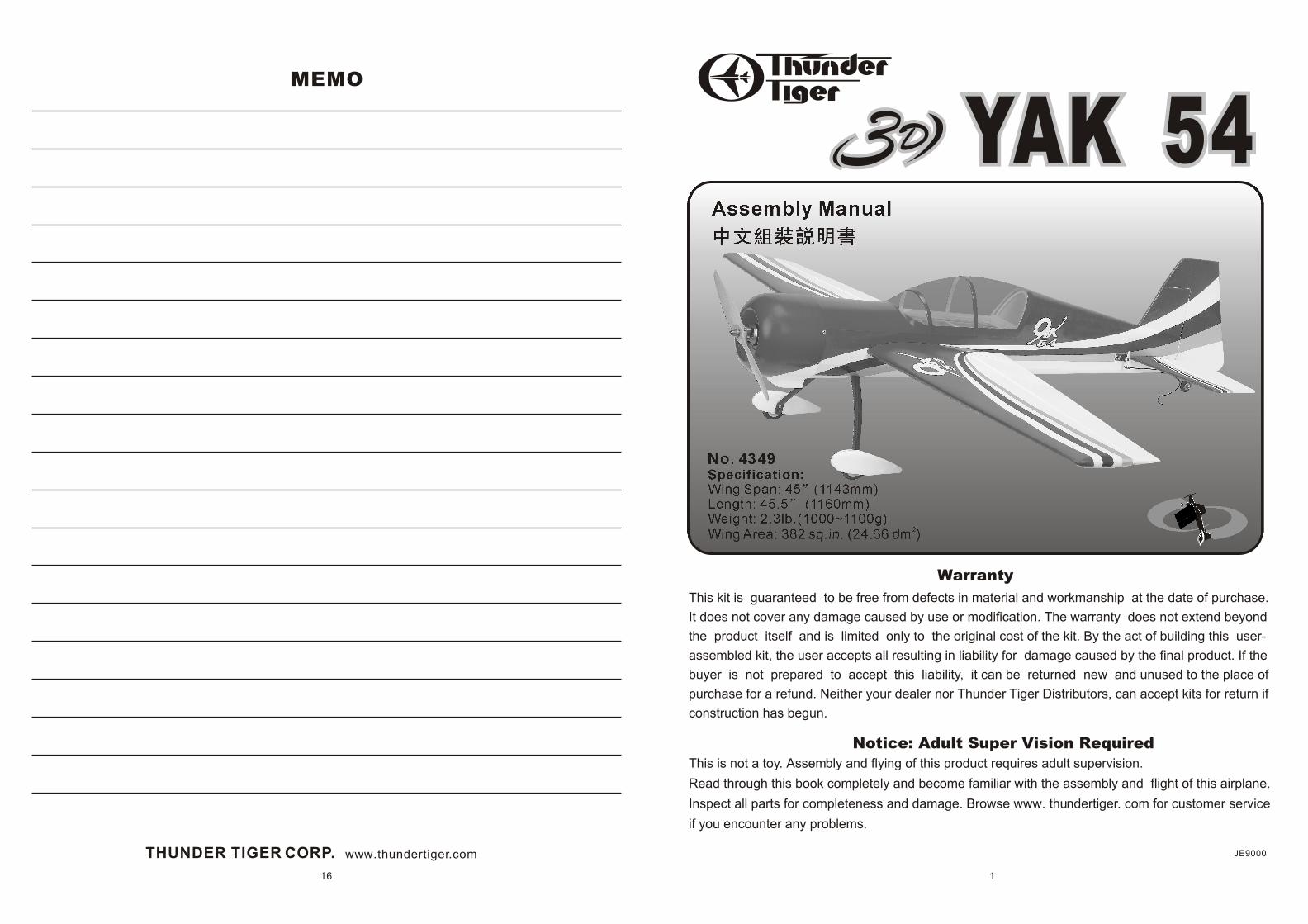
Warranty
This kit is guaranteed to be free from defects in material and workmanship at the date of purchase.
It does not cover any damage caused by use or modification. The warranty does not extend beyond
the product itself and is limited only to the original cost of the kit. By the act of building this user-
assembled kit, the user accepts all resulting in liability for damage caused by the final product. If the
buyer is not prepared to accept this liability, it can be returned new and unused to the place of
purchase for a refund. Neither your dealer nor Thunder Tiger Distributors, can accept kits for return if
construction has begun.
Notice: Adult Super Vision Required
This is not a toy. Assembly and flying of this product requires adult supervision.
Read through this book completely and become familiar with the assembly and flight of this airplane.
Inspect all parts for completeness and damage. Browse www. thundertiger. com for customer service
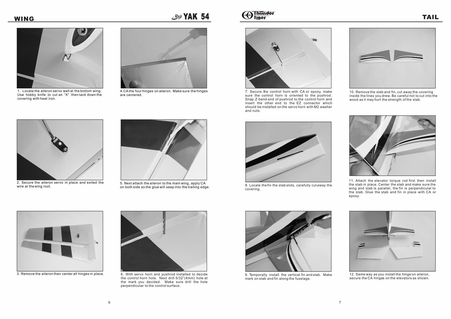
1. Locate the aileron servo well at the bottom wing. Use hobby knife to cut an “X” then tack down thecovering with heat iron.
2. Secure the aileron servo in place and exited the wire at the wing root.
3. Remove the aileron then center all hinges in place.
4.CA the four hinges on aileron. Make sure the hingesare centered.
5. Next attach the aileron to the main wing, apply CAon both side so the glue will seep into the trailing edge.
6. With servo horn and pushrod installed to decide the control horn hole. Next drill 5/32”(4mm) hole at the mark you decided. Make sure drill the hole perpendicular to the control surface.
7. Secure the control horn with CA or epoxy, make sure the control horn is oriented to the pushrod. Snap Z-bend end of pushrod to the control horn and insert the other end to the EZ connector which should be installed on the servo horn with M2 washer and nuts.
9. Temporally install the vertical fin and stab. Make mark on stab and fin along the fuselage.
10. Remove the stab and fin, cut away the coveringinside the lines you drew. Be careful not to cut into thewood as it may hurt the strength of the stab.
11. Attach the elevator torque rod first then install the stab in place. Center the stab and make sure the wing and stab is parallel, the fin is perpendicular to the stab. Glue the stab and fin in place with CA or epoxy.
12. Same way as you install the hinge on aileron,secure the CA hinges on the elevators as shown.
8. Locate the fin the stab slots, carefully cut away thecovering.
TAIL
8
MOTOR
9
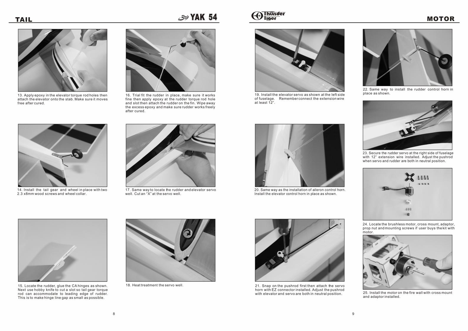
14. Install the tail gear and wheel in place with two2.3 x8mm wood screws and wheel collar.
15. Locate the rudder, glue the CA hinges as shown. Next use hobby knife to cut a slot so tail gear torque rod can accommodate to leading edge of rudder. This is to make hinge line gap as small as possible.
16. Trial fit the rudder in place, make sure it works fine then apply epoxy at the rudder torque rod hole and slot then attach the rudder on the fin. Wipe away the excess epoxy and make sure rudder works freely after cured.
17. Same way to locate the rudder and elevator servowell. Cut an “X” at the servo well.
18. Heat treatment the servo well.
19. Install the elevator servo as shown at the left sideof fuselage. Remember connect the extension wireat least 12”.
20. Same way as the installation of aileron control horn.Install the elevator control horn in place as shown.
21. Snap on the pushrod first then attach the servo horn with EZ connector installed. Adjust the pushrod with elevator and servo are both in neutral position.
22. Same way to install the rudder control horn inplace as shown.
23. Secure the rudder servo at the right side of fuselagewith 12” extension wire installed. Adjust the pushrodwhen servo and rudder are both in neutral position.
24. Locate the brushless motor, cross mount, adaptor,prop nut and mounting screws if user buys the kit withmotor.
13. Apply epoxy in the elevator torque rod holes thenattach the elevator onto the stab. Make sure it movesfree after cured.
25. Install the motor on the fire wall with cross mountand adaptor installed.
RADIO
10
COWL
11
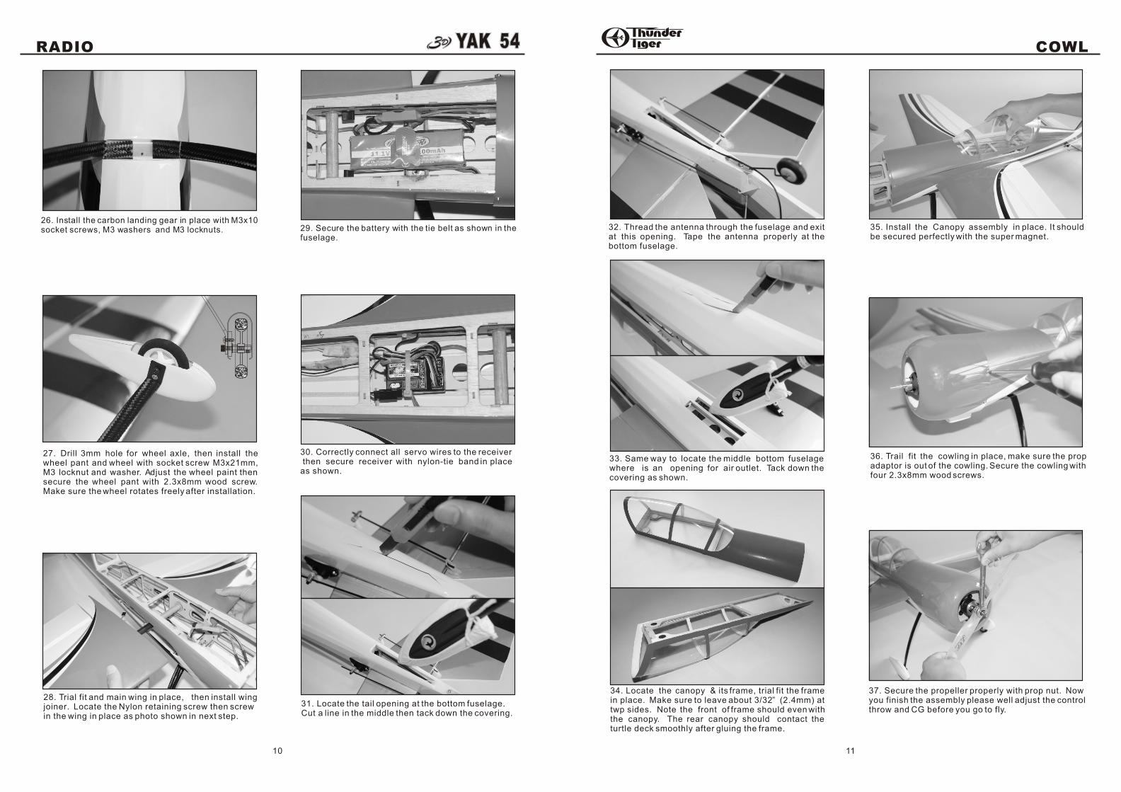
26. Install the carbon landing gear in place with M3x10socket screws, M3 washers and M3 locknuts.
27. Drill 3mm hole for wheel axle, then install the wheel pant and wheel with socket screw M3x21mm, M3 locknut and washer. Adjust the wheel paint then secure the wheel pant with 2.3x8mm wood screw. Make sure the wheel rotates freely after installation.
28. Trial fit and main wing in place, then install wingjoiner. Locate the Nylon retaining screw then screwin the wing in place as photo shown in next step.
30. Correctly connect all servo wires to the receiver then secure receiver with nylon-tie band in placeas shown.
31. Locate the tail opening at the bottom fuselage. Cut a line in the middle then tack down the covering.
32. Thread the antenna through the fuselage and exitat this opening. Tape the antenna properly at thebottom fuselage.
33. Same way to locate the middle bottom fuselagewhere is an opening for air outlet. Tack down thecovering as shown.
34. Locate the canopy & its frame, trial fit the frame in place. Make sure to leave about 3/32” (2.4mm) at twp sides. Note the front of frame should even with the canopy. The rear canopy should contact theturtle deck smoothly after gluing the frame.
36. Trail fit the cowling in place, make sure the propadaptor is out of the cowling. Secure the cowling withfour 2.3x8mm wood screws.
37. Secure the propeller properly with prop nut. Nowyou finish the assembly please well adjust the controlthrow and CG before you go to fly.
29. Secure the battery with the tie belt as shown in thefuselage.
35. Install the Canopy assembly in place. It shouldbe secured perfectly with the super magnet.
CONTROL THROWS BALANCE
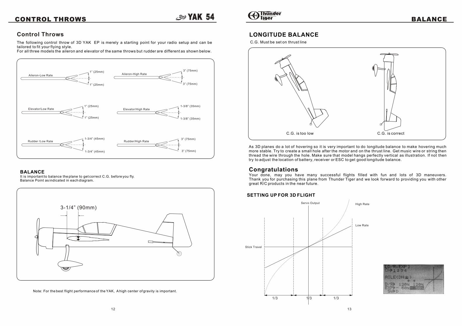
LONGITUDE BALANCEC.G. Must be set on thrust line
C.G. is too low C.G. is correct
As 3D planes do a lot of hovering so it is very important to do longitude balance to make hovering much more stable. Try to create a small hole after the motor and on the thrust line. Get music wire or string then thread the wire through the hole. Make sure that model hangs perfectly vertical as illustration. If not then try to adjust the location of battery, receiver or ESC to get good longitude balance.
CongratulationsYour done, may you have many successful flights filled with fun and lots of 3D maneuvers.Thank you for purchasing this plane from Thunder Tiger and we look forward to providing you with other great R/C products in the near future.
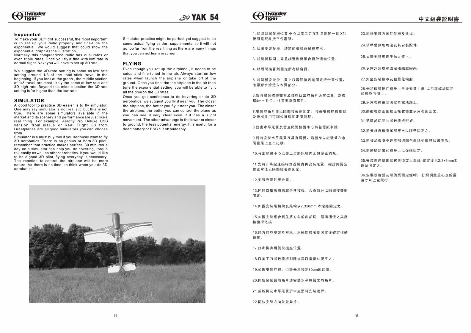
SETTING UP FOR 3D FLIGHT
1/3 1/3 1/3
Stick Travel
Servo Output High Rate
Low Rate
13
The following control throw of 3D YAK EP is merely a starting point for your radio setup and can be tailored to fit your flying style.For all three models the aileron and elevator of the same throws but rudder are different as shown below.
Elevator/Low Rate1” (25mm)
Aileron-High Rate3” (75mm)
Aileron-Low Rate1” (25mm)
1” (25mm)
Elevator/High Rate
Control Throws
BALANCEIt is important to balance the plane to get correct C.G. before you fly.Balance Point as indicated in each diagram.
Note: For the best flight performance of the YAK, A high center of gravity is important.
3” (75mm)
1” (25mm)
1-3/8” (35mm)
1-3/8” (35mm)
3-1/4” (90mm)
12
Rudder /Low Rate Rudder/High Rate
1-3/4” (45mm)
1-3/4” (45mm) 3” (75mm)
3” (75mm)
15
1. X
2.
3.
4.
5.
6.
4mm
7.
8.
9.
10.
11.
12.
13.
14. 2.3x8mm
15.
16.
17.
18.
19. 30cm
20.
21.
22.
23.
24.
25.
26.
27.
28. ,
29.
30.
31.
32.
33.
34.
35. , 2.3x8mm
36.
ExponetialTo make your 3D flight successful, the most important is to set up your radio properly and fine-tune the exponential. We would suggest that could show the exponential graph as the illustration.Normally this computerized radio has dual rates or even triple rates. Once you fly it fine with low rate in normal flight. Next you will have to set up 3D rate.
We suggest the 3D-rate setting is same as low rate setting around 1/3 of the total stick travel in the beginning. If you look at the graph , the middle section of 1/3 travel are most likely the same at low rate and 3D high rate .Beyond this middle section the 3D rate setting is far higher than the low rate.
SIMULATORA good tool to practice 3D easier is to fly simulator. One may say simulator is not realistic but this is not true. There are some simulators available in the market and its scenery and performance are just like a real thing .For example, Aerofly Pro Deluxe USB vers ion f rom ikarus o r Rea l F l igh t G3 f rom Greatplanes are all good simulators you can choose from .Simulator is a must buy tool if you seriously want to fly 3D aerobatics. There is no genius or born 3D pilot, remember that practice makes perfect. 30 minutes a day on a simulator can help you do hovering, torque roll easily as well as other aerobatics. If you would like to be a good 3D pilot, flying everyday is necessary. The reaction to control the airplane will be more nature. As there is no time to think when you do 3D aerobatics.
Simulator practice might be perfect yet suggest to do
some actual flying as the supplemental so it will not
go too far from the real thing as there are many things
that you can not learn in screen.
FLYINGEven though you set up the airplane , it needs to be
setup and fine-tuned in the air. Always start on low
rates when launch the airplane or take off of the
ground. Once you fine trim the airplane in the air then
tune the exponential setting, you will be able to fly it
all the time on the 3D rates.
Once you got confidence to do hovering or do 3D
aerobatics, we suggest you fly it near you. The closer
the airplane, the better you fly it near you. The closer
the airplane, the better you can control the plane as
you can see it very clear even if it has a slight
movement. The other advantage is the lower or closer
to ground, the less potential energy. It is useful for a