Page 1 of 3 MEMO TO FILE DATE: April 5, 2016 SUBJECT: Southern Ute Indian Reservation; BP America Production Company, National Historic Preservation Act FROM: Victoria Parker-Christensen, EPA Region 8 Air Program TO: Source Files: 205c AirTribal SU BP America Salvador I/II Central Delivery Point SMNSR-SU-000009-2015.003 FRED # 108006 Section 106 of the National Historic Preservation Act (NHPA) requires federal agencies to take into account the effects of their undertakings on historic properties and afford the Advisory Council on Historic Preservation (ACHP) a reasonable opportunity to comment with regard to such undertakings. Under the ACHP’s implementing regulations at 36 C.F.R. Part 800, Section 106 consultation is generally with state and tribal historic preservation officials in the first instance, with opportunities for the ACHP to become directly involved in certain cases. An “undertaking” is “a project, activity, or program funded in whole or in part under the direct or indirect jurisdiction of a Federal agency, including those carried out by or on behalf of a Federal agency; those carried out with Federal financial assistance; and those requiring a Federal permit, license or approval.” 36 C.F.R. § 800.16(y). If an undertaking is a type of activity that does not have the potential to cause effects on historic properties, assuming such historic properties were present, the federal agency has no further obligations under 36 C.F.R. § 800.3(a)(1). Under the NHPA Section 106 implementing regulations, federal agencies consult with relevant historic preservation partners to determine the area of potential effect (APE) of the undertaking, to identify historic properties that may exist in that area, and to assess and address any adverse effects that may be caused on such properties by the undertaking. Specifically, 36 C.F.R. § 800.4(b)(1) of the regulations states that federal agency officials shall make a “reasonable and good faith effort” to identify historic properties. This memorandum describes EPA’s efforts to identify historic properties and assess potential effects in connection with issuing a Clean Air Act (CAA) synthetic minor New Source Review (NSR) permit located within the exterior boundaries of the Southern Ute Indian Reservation in La Plata County, Colorado. Region 8, Air Program Determination The EPA reviewed the proposed action for potential impacts on historic properties in the area of potential effects (APE). The proposed permit action authorizes construction of a new emission source, and establishes legally and practically enforceable emission limitations for the new emissions source and an existing emissions source. While there is construction of a new emission source, the new source will
Transcript
Page 1 of 3
MEMO TO FILE
DATE: April 5, 2016
SUBJECT: Southern Ute Indian Reservation; BP America Production Company, National Historic
Preservation Act
FROM: Victoria Parker-Christensen, EPA Region 8 Air Program
TO: Source Files:
205c AirTribal SU BP America Salvador I/II Central Delivery Point
SMNSR-SU-000009-2015.003
FRED # 108006
Section 106 of the National Historic Preservation Act (NHPA) requires federal agencies to take into
account the effects of their undertakings on historic properties and afford the Advisory Council on
Historic Preservation (ACHP) a reasonable opportunity to comment with regard to such undertakings.
Under the ACHP’s implementing regulations at 36 C.F.R. Part 800, Section 106 consultation is
generally with state and tribal historic preservation officials in the first instance, with opportunities for
the ACHP to become directly involved in certain cases. An “undertaking” is “a project, activity, or
program funded in whole or in part under the direct or indirect jurisdiction of a Federal agency,
including those carried out by or on behalf of a Federal agency; those carried out with Federal financial
assistance; and those requiring a Federal permit, license or approval.” 36 C.F.R. § 800.16(y).
If an undertaking is a type of activity that does not have the potential to cause effects on historic
properties, assuming such historic properties were present, the federal agency has no further obligations
under 36 C.F.R. § 800.3(a)(1). Under the NHPA Section 106 implementing regulations, federal agencies
consult with relevant historic preservation partners to determine the area of potential effect (APE) of the
undertaking, to identify historic properties that may exist in that area, and to assess and address any
adverse effects that may be caused on such properties by the undertaking. Specifically, 36 C.F.R. §
800.4(b)(1) of the regulations states that federal agency officials shall make a “reasonable and good faith
effort” to identify historic properties.
This memorandum describes EPA’s efforts to identify historic properties and assess potential effects in
connection with issuing a Clean Air Act (CAA) synthetic minor New Source Review (NSR) permit
located within the exterior boundaries of the Southern Ute Indian Reservation in La Plata County,
Colorado.
Region 8, Air Program Determination
The EPA reviewed the proposed action for potential impacts on historic properties in the area of
potential effects (APE). The proposed permit action authorizes construction of a new emission source,
and establishes legally and practically enforceable emission limitations for the new emissions source and
an existing emissions source. While there is construction of a new emission source, the new source will
Page 2 of 3
be located within the existing footprint of the facility in a previously disturbed area and does not require
additional infrastructure (road, power line, pipeline). Because the EPA has determined that the federal
action will have no effect, the agency is making the finding of “No historic properties affected” for the
APE.
Area of Potential Effects
The APE for the existing facility is the location within the area currently occupied by the facility.
Example Calculations:NOX Emissions (lb/hr) = 1138 hp * 0.00 g/hp-hr * lb/453.6 g = 6.42NOX Emissions (TPY) =
[5] Based on AP-42, Fifth Edition, Volume 1, Chapter 3, Section 3.2, Table 3.2-2 Uncontrolled Emission Factors For 4-Stroke Lean-Burn Engines, 7/00. PM emission factor is the sum of PMfilterable and PMcondensable.
[1] Based on Caterpillar Gas Engine Rating Pro Version 5.05.00 (Ref. Data Set DM8620-
05-001) for Caterpillar G3516, 1200 rpm, 8:1 CR, 130 oF aftercooler water inlet, TA aspiration, ADEM3 & AFR, maximum rating. Site rating based on deducting 3% for every 1000 feet above 6000 feet. Using fuel consumption (HHV) value. VOC emission factor is the sum of the NMNEHC and CH2O emission factors.
6.42 lb/hr * 8760 hr/yr * 1 Ton/2000 lb = 28.12
[3] Heat input based on fuel consumption and site-rated HP. Fuel usage rates based on fuel consumption x site-rated hp / 800 Btu/scf conservative heating value.
[2] Conservatively based on full time operating hours and full capacity.
[4] NOx emission factor is from 12/9/15 NSPS JJJJ Test and is higher than the manufacturer's specification (test 2.55 g/hp-hr, spec 2.0 g/hp-hr). Engine was tested above 100% load so mass emission rate (lb/hr) is being used for PTE calculation to be conservative.
BP America Production CompanyFacility: Salvador I/II Central Delivery PointDescription: Potential-to-Emit Greenhouse Gas Emissions Summary
CO2 CH4 N2O CO2e
Unit 1 1334 hp Waukesha L7042GL Compressor Engine w/OxiCat 4,886.6770 0.0922 0.0092 4,891.7278
Unit 2 1138 hp Caterpillar G3516 Compressor Engine 4,353.1731 0.0820 0.0082 4,357.6690
Unit 3 1334 hp Waukesha L7042GL Compressor Engine 4,886.6770 0.0922 0.0092 4,891.7278
Unit 4 1467 hp Waukesha L7042GSI Compressor Engine w/NSCR and AFRC 5,858.3172 0.1105 0.0110 5,864.3722
-- 500 gal TEG Tanks (3) 0.0000 0.0000 0.0000 0.0000
[1] Based on Caterpillar Gas Engine Rating Pro Version 5.05.00 (Ref. Data Set DM8620-05-001) for Caterpillar G3516, 1200 rpm, 8:1 CR, 130 oF aftercooler water inlet, TA aspiration, ADEM3 & AFR, maximum rating. Site rating based on deducting 3% for every 1000 feet above 6000 feet. Using fuel consumption (HHV) value. [2] Conservatively based on full time operating hours and full capacity.[3] Heat input based on fuel consumption and site-rated HP.
Fuel-specific default CO2, CH4, or N2O emission factors from Table C-1 for CO2
(Natural gas - Weighted U.S. Average) and Table C-2 for CH 4 and N2O (Natural Gas) of 40 CFR Part 98, Subpart C (kg/MMBtu)
Data generated by Gas Engine Rating Pro Version 5.05.00Ref. Data Set DM8620-05-001, Printed 30Oct2015 Page 1 of 4
G3516 GAS ENGINE TECHNICAL DATA
ENGINE SPEED (rpm): 1200 RATING STRATEGY: STANDARDCOMPRESSION RATIO: 8 APPLICATION: GAS COMPRESSIONAFTERCOOLER TYPE: SCAC RATING LEVEL: CONTINUOUSAFTERCOOLER WATER INLET (°F): 130 FUEL: NAT GASJACKET WATER OUTLET (°F): 210 FUEL SYSTEM: HPG IMPCOASPIRATION: TA WITH AIR FUEL RATIO CONTROLCOOLING SYSTEM: JW+OC, AC FUEL PRESSURE RANGE(psig): 35.0-40.0CONTROL SYSTEM: ADEM3 FUEL METHANE NUMBER: 80EXHAUST MANIFOLD: ASWC FUEL LHV (Btu/scf): 905COMBUSTION: LOW EMISSION ALTITUDE CAPABILITY AT 77°F INLET AIR TEMP. (ft): 6125NOx EMISSION LEVEL (g/bhp-hr NOx): 2.0
HEAT REJECTION TO EXHAUST (LHV TO 77°F) (20)(21) Btu/min 39536 29811 20210
HEAT REJECTION TO EXHAUST (LHV TO 350°F) (20) Btu/min 25159 19038 13031
HEAT REJECTION TO AFTERCOOLER (AC) (22)(25) Btu/min 7509 4110 1403
PUMP POWER (23) Btu/min 977 977 977
CONDITIONS AND DEFINITIONSEngine rating obtained and presented in accordance with ISO 3046/1. (Standard reference conditions of 77°F, 29.60 in Hg barometric pressure.) No overload permitted at ratingshown. Consult the altitude deration factor chart for applications that exceed the rated altitude or temperature.
Emission levels are at engine exhaust flange prior to any after treatment. Values are based on engine operating at steady state conditions, adjusted to the specified NOx level at 100%load. Tolerances specified are dependent upon fuel quality. Fuel methane number cannot vary more than ± 3.
For notes information consult page three.
Data generated by Gas Engine Rating Pro Version 5.05.00Ref. Data Set DM8620-05-001, Printed 30Oct2015 Page 1 of 4
Data generated by Gas Engine Rating Pro Version 5.05.00Ref. Data Set DM8620-05-001, Printed 30Oct2015 Page 2 of 4
G3516 GAS ENGINE TECHNICAL DATA
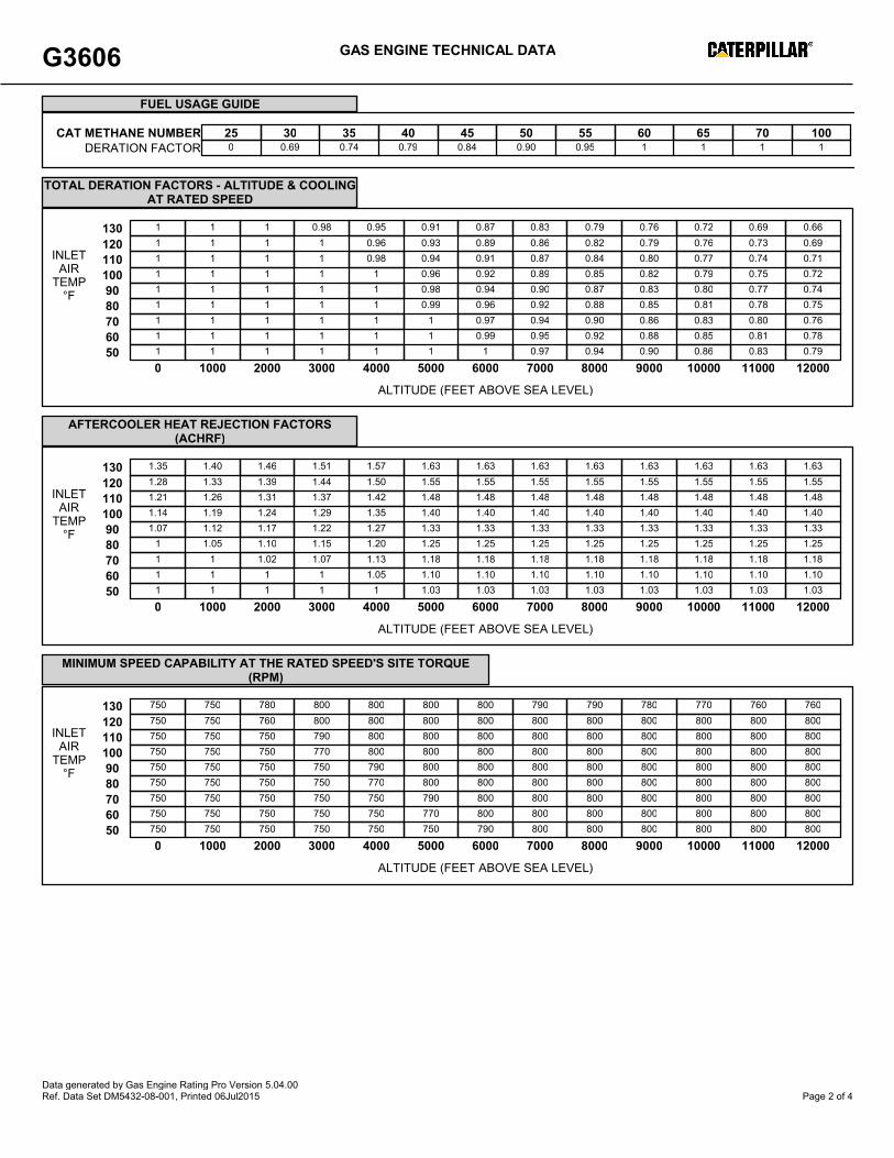
FUEL USAGE GUIDE:This table shows the derate factor and full load set point timing required for a given fuel. Note that deration and set point timing adjustment may be required as the methane numberdecreases. Methane number is a scale to measure detonation characteristics of various fuels. The methane number of a fuel is determined by using the Caterpillar methane numbercalculation.
ALTITUDE DERATION FACTORS:This table shows the deration required for various air inlet temperatures and altitudes. Use this information along with the fuel usage guide chart to help determine actual engine power foryour site.
ACTUAL ENGINE RATING:To determine the actual rating of the engine at site conditions, one must consider separately, limitations due to fuel characteristics and air system limitations. The Fuel Usage Guidederation establishes fuel limitations. The Altitude/Temperature deration factors and RPC (reference the Caterpillar Methane Program) establish air system limitations. RPC comes intoplay when the Altitude/Temperature deration is less than 1.0 (100%). Under this condition, add the two factors together. When the site conditions do not require an Altitude/Temperature derate (factor is 1.0), it is assumed the turbocharger has sufficient capability to overcome the low fuel relative power, and RPC is ignored. To determine the actual poweravailable, take the lowest rating between 1) and 2).1) Fuel Usage Guide Deration2) 1-((1-Altitude/Temperature Deration) + (1-RPC))
AFTERCOOLER HEAT REJECTION FACTORS(ACHRF):To maintain a constant air inlet manifold temperature, as the inlet air temperature goes up, so must the heat rejection. As altitude increases, the turbocharger must work harder toovercome the lower atmospheric pressure. This increases the amount of heat that must be removed from the inlet air by the aftercooler. Use the aftercooler heat rejection factor (ACHRF)to adjust for inlet air temp and altitude conditions. See note 25 for application of this factor in calculating the heat exchanger sizing criteria. Failure to properly account for these factorscould result in detonation and cause the engine to shutdown or fail.
MINIMUM SPEED CAPABILITY AT THE RATED SPEED'S SITE TORQUE (RPM):This table shows the minimum allowable engine turndown speed where the engine will maintain the Rated Speed’s Torque for the given ambient conditions.
NOTES:1. Engine rating is with two engine driven water pumps. Tolerance is ± 3% of full load.2. ISO 3046/1 engine efficiency tolerance is (+)0, (-)5% of full load % efficiency value. Nominal engine efficiency tolerance is ± 3.0% of full load % efficiency value.3. ISO 3046/1 fuel consumption tolerance is (+)5, (-)0% of full load data. Nominal fuel consumption tolerance is ± 3.0% of full load data.4. Air flow value is on a 'wet' basis. Flow is a nominal value with a tolerance of ± 5 %.5. Inlet and Exhaust Restrictions must not exceed A&I limits based on full load flow rates from the standard technical data sheet.6. Inlet manifold pressure is a nominal value with a tolerance of ± 5 %.7. Inlet manifold temperature is a nominal value with a tolerance of ± 9°F.8. Timing indicated is for use with the minimum fuel methane number specified. Consult the appropriate fuel usage guide for timing at other methane numbers.9. Exhaust temperature is a nominal value with a tolerance of (+)63°F, (-)54°F.10. Exhaust flow value is on a 'wet' basis. Flow is a nominal value with a tolerance of ± 6 %.11. Emissions data is at engine exhaust flange prior to any after treatment.12. NOx values are "Not to Exceed".13. CO, CO2, THC, NMHC, NMNEHC, and HCHO values are "Not to Exceed" levels. THC, NMHC, and NMNEHC do not include aldehydes. An oxidation catalyst may be required tomeet Federal, State or local CO or HC requirements.14. VOCs - Volatile organic compounds as defined in US EPA 40 CFR 60, subpart JJJJ15. Exhaust Oxygen tolerance is ± 0.5; Lambda tolerance is ± 0.05. Lambda and Exhaust Oxygen level are the result of adjusting the engine to operate at the specified NOx level.16. LHV rate tolerance is ± 3.0%.17. Heat rejection to jacket water value displayed includes heat to jacket water alone. Value is based on treated water. Tolerance is ± 10% of full load data.18. Heat rejection to atmosphere based on treated water. Tolerance is ± 50% of full load data.19. Lube oil heat rate based on treated water. Tolerance is ± 20% of full load data.20. Exhaust heat rate based on treated water. Tolerance is ± 10% of full load data.21. Heat rejection to exhaust (LHV to 77°F) value shown includes unburned fuel and is not intended to be used for sizing or recovery calculations.22. Heat rejection to aftercooler based on treated water. Tolerance is ±5% of full load data.23. Pump power includes engine driven jacket water and aftercooler water pumps. Engine brake power includes effects of pump power.24. Total Jacket Water Circuit heat rejection is calculated as: (JW x 1.1) + (OC x 1.2). Heat exchanger sizing criterion is maximum circuit heat rejection at site conditions, with appliedtolerances. A cooling system safety factor may be multiplied by the total circuit heat rejection to provide additional margin.25. Total Aftercooler Circuit heat rejection is calculated as: AC x ACHRF x 1.05. Heat exchanger sizing criterion is maximum circuit heat rejection at site conditions, with appliedtolerances. A cooling system safety factor may be multiplied by the total circuit heat rejection to provide additional margin.
Data generated by Gas Engine Rating Pro Version 5.05.00Ref. Data Set DM8620-05-001, Printed 30Oct2015 Page 3 of 4
G3516 GAS ENGINE TECHNICAL DATA
ENGINE POWER (bhp): 1150 COOLING SYSTEM: JW+OC, ACENGINE SPEED (rpm): 1200 AFTERCOOLER WATER INLET (°F): 130EXHAUST MANIFOLD: ASWC JACKET WATER OUTLET (°F): 210
Free Field Mechanical and Exhaust NoiseSOUND PRESSURE LEVEL (dB)
SOUND PARAMETER DEFINITION:Data Variability Statement:Sound data presented by Caterpillar has been measured in accordance with ISO 6798 in a Grade 3 test environment. Measurements madeinaccordance with ISO 6798 will result in some amount of uncertainty. The uncertainties depend not only on the accuracies with which soundpressurelevels and measurement surface areas are determined, but also on the 'near-field error' which increases for smaller measurement distancesand lowerfrequencies. The uncertainty for a Grade 3 test environment, that has a source that produces sounds that are uniformly distributed infrequency over thefrequency range of interest, is equal to 4 dB (A-weighted). This uncertainty is expressed as the largest value of the standarddeviation.
Data generated by Gas Engine Rating Pro Version 5.05.00Ref. Data Set DM8620-05-001, Printed 30Oct2015 Page 4 of 4
Xylenek 1.84 E-04 Ba Reference 7. Factors represent uncontrolled levels. For NOx, CO, and PM10,
“uncontrolled” means no combustion or add-on controls; however, the factor may includeturbocharged units. For all other pollutants, “uncontrolled” means no oxidation control;the data set may include units with control techniques used for NOx control, such as PCCand SCR for lean burn engines, and PSC for rich burn engines. Factors are based on largepopulation of engines. Factors are for engines at all loads, except as indicated. SCC =Source Classification Code. TOC = Total Organic Compounds. PM-10 = ParticulateMatter 10 microns ( m) aerodynamic diameter. A “<“ sign in front of a factor meansthat the corresponding emission factor is based on one-half of the method detection limit.
b Emission factors were calculated in units of (lb/MMBtu) based on procedures in EPAMethod 19. To convert from (lb/MMBtu) to (lb/106 scf), multiply by the heat content ofthe fuel. If the heat content is not available, use 1020 Btu/scf. To convert from(lb/MMBtu) to (lb/hp-hr) use the following equation:
c Emission tests with unreported load conditions were not included in the data set.d Based on 99.5% conversion of the fuel carbon to CO2. CO2 [lb/MMBtu] =
(3.67)(%CON)(C)(D)(1/h), where %CON = percent conversion of fuel carbon to CO2,C = carbon content of fuel by weight (0.75), D = density of fuel, 4.1 E+04 lb/106 scf, and
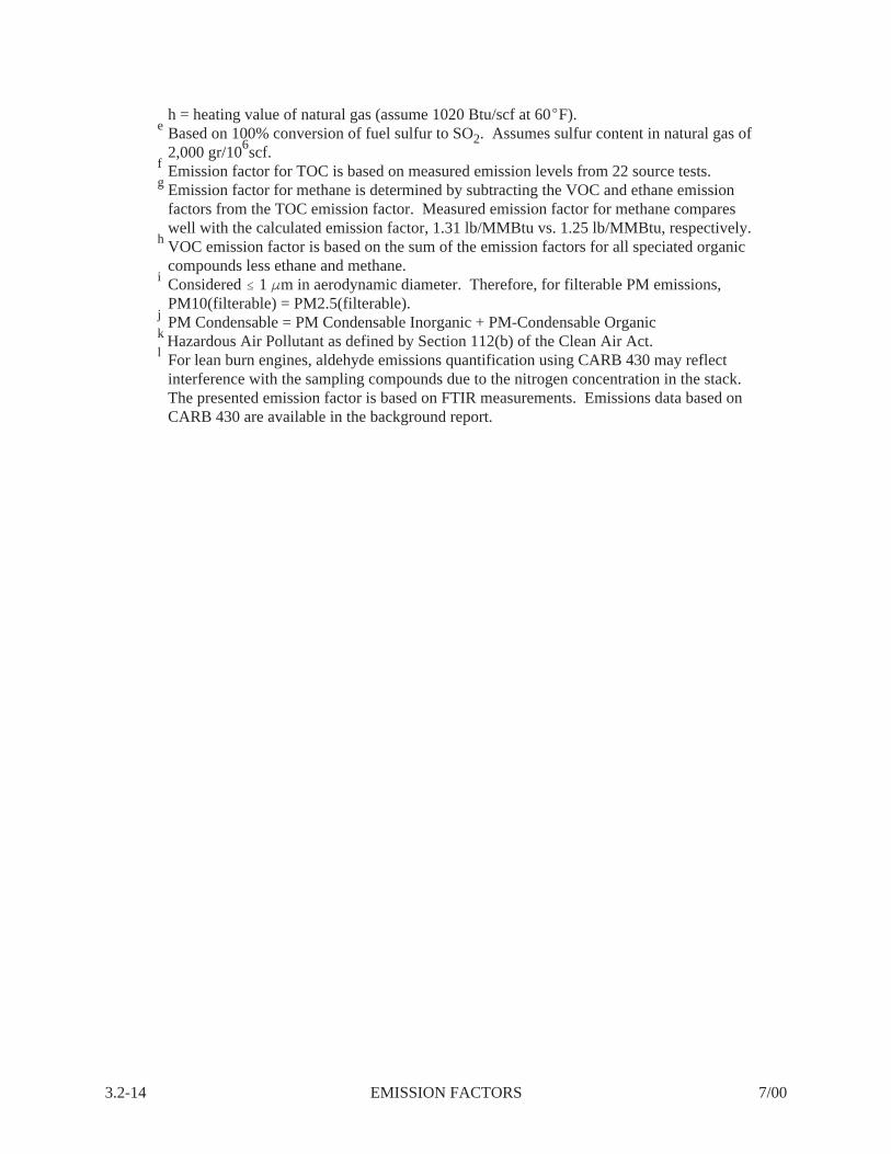
3.2-14 EMISSION FACTORS 7/00
h = heating value of natural gas (assume 1020 Btu/scf at 60 F).e Based on 100% conversion of fuel sulfur to SO2. Assumes sulfur content in natural gas of
2,000 gr/106scf.f Emission factor for TOC is based on measured emission levels from 22 source tests.g Emission factor for methane is determined by subtracting the VOC and ethane emission
factors from the TOC emission factor. Measured emission factor for methane compareswell with the calculated emission factor, 1.31 lb/MMBtu vs. 1.25 lb/MMBtu, respectively.
h VOC emission factor is based on the sum of the emission factors for all speciated organiccompounds less ethane and methane.
i Considered 1 m in aerodynamic diameter. Therefore, for filterable PM emissions,PM10(filterable) = PM2.5(filterable).
j PM Condensable = PM Condensable Inorganic + PM-Condensable Organick Hazardous Air Pollutant as defined by Section 112(b) of the Clean Air Act.l For lean burn engines, aldehyde emissions quantification using CARB 430 may reflect
interference with the sampling compounds due to the nitrogen concentration in the stack. The presented emission factor is based on FTIR measurements. Emissions data based onCARB 430 are available in the background report.
40 CFR Part 98‚ Table C-1 to subpart C - Default Co2 Emission Factors and High Heat Values for Various Types of Fuel
Table C-1 to Subpart C of Part 98 Default Co2 Emission Factors and High Heat Values for Various Types of Fuel
Default CO2 Emission Factors and High Heat Values for Various Types of Fuel
Note: Those employing this table are assumed to fall under the IPCC definitions of the “Energy Industry” or “Manufacturing Industries and Construction”. In all fuels except for coal the values for these two categories are identical. For coal combustion, those who fall within the IPCC “Energy Industry” category may employ a value of 1g of CH4/mmBtu.
[78 FR 71952, Nov. 29, 2013]
| Home | CFR | 40 CFR | Clean Air Act / Air Programs (CAA) | Top |
Subject: Salvador I/II CDP – Notification of Unpermitted Engine Replacement
Dear Federal Minor NSR Coordinator:
BP America Production Company (BP) is submitting this notification of an unpermitted engine replacement at the
Salvador I/II Central Delivery Point (CDP). The site is an existing synthetic minor source with enforceable emission
limitations and requirements established for two engines under permit number SMNSR-SU-000009-2012.002. BP is
planning to replace an unpermitted 666 site-rated horsepower four-stroke lean burn compressor engine (identified as
Emission Unit ID Unit 2 or C200) with a 1,073 site-rated horsepower four-stroke lean burn compressor engine in August
2015. Neither the existing engine nor the replacement engine requires any air emission control devices. Since the
change in emissions results in an increase in nitrogen oxides emissions greater than the thresholds listed in Table 1 of
EPA’s Federal Minor New Source Review Program in Indian Country (40 CFR 49.153 – 49.161) for attainment areas, BP is
submitting this notification to update the registration information for the site. The potential-to-emit calculations for
the replacement engine, updated site emissions summaries including the changes in emissions at the site, and
supporting documentation are attached.
2
Within one year of commencing operation of the replacement engine, BP will submit an application for an operating
permit in accordance with the Southern Ute Indian Tribe/State of Colorado Environmental Commission’s Reservation Air
Code since the potential-to-emit carbon monoxide emissions at the Salvador I/II CDP will be greater than 100 tons per
year.
If you have any questions regarding this notification or require additional information, please contact me at (281) 366-
3946 or Julie Best at (970) 375-7540.
Sincerely,
Rebecca Robert
Air Engineer
BP US Lower 48 Onshore
Office: (281) 366-3946
Cell: (713) 540-9959
***NEW MAILING ADDRESS***
737 North Eldridge Parkway
Houston, Texas 77079
BP America Production Company
Federal Minor New Source Review Program in
Indian Country Synthetic Minor Permit Application
to Construct a 1,874 HP Four-Stroke Lean Burn Compressor Engine with Oxidation Catalyst and
to Establish Legally and Practically Enforceable Limitations and Requirements on Two Engines
Salvador I/II Central Delivery Point
La Plata County, CO
August 2015, revised October 2015
Salvador I/II Central Delivery Point i BP America Production Company August 2015, rev Oct 2015 TRIBAL MNSR SYNTHETIC MINOR PERMIT APPLICATION
TABLE OF CONTENTS
1 INTRODUCTION............................................................................................................ 1-1 1.1 Purpose ............................................................................................................... 1-1 1.2 Application Forms for Synthetic Minor Limit .................................................... 1-1
2 FACILITY INFORMATION ......................................................................................... 2-1 2.1 Process and Product Description ........................................................................ 2-1 2.2 Process Flow Diagram ........................................................................................ 2-1 2.3 Operating Schedule ............................................................................................. 2-1
3 AFFECTED EMISSION UNITS .................................................................................... 3-1 3.1 Affected Emission Units and Emission Calculations ......................................... 3-1 3.2 Identification and Description of Existing Air Pollution Control Equipment and
Requested Synthetic Minor Limits ..................................................................... 3-1 3.3 Proposed Testing, Monitoring, Recordkeeping and Reporting Requirements ... 3-2 3.4 Type and Quantity of Fuel and Raw Materials Used ......................................... 3-2
4 AIR QUALITY REVIEW……………………………..……………………………….4-1
LIST OF SUPPLEMENTAL DOCUMENTS
1 Form NEW ................................................................................................................ 1-2 2 Form SYNMIN ................................................................................................................ 1-3 3 Simplified Process Flow Diagram ...................................................................................... 2-2 4 Proposed Operational, Testing, Monitoring, Recordkeeping & Reporting Requirements . 3-3 5 Potential-to-Emit Emission Calculations and Supporting Documentation ......................... 3-4 6 Actual Emission Calculations and Supporting Documentation .......................................... 3-5
Salvador I/II Central Delivery Point 1-1 BP America Production Company August 2015, rev Oct 2015 TRIBAL MNSR SYNTHETIC MINOR PERMIT APPLICATION
1 INTRODUCTION
1.1 Purpose On July 1, 2011, the United States Environmental Protection Agency (USEPA) published 40 CFR 49.151-161, the Federal Minor New Source Review (mNSR) Program in Indian Country, which became effective on August 30, 2011. BP America Production Company’s (BP) Salvador I/II Central Delivery Point is an existing synthetic minor source with nitrogen oxides (NOx), carbon monoxide (CO), and formaldehyde (CH2O) emission limits established for two compressor engines under permit number SMNSR-SU-000009-2012-002. BP is submitting this permit application to construct a 1,874, or lower, site-rated horsepower (hp) four-stroke lean burn compressor engine with oxidation catalyst at the site and to establish legally and practically enforceable CO and CH2O limitations and requirements for this engine as well as for a 1,138, or lower, site rated hp four-stroke lean burn compressor engine that will replace an unpermitted engine at the site. BP notified USEPA of this planned unpermitted engine replacement on July 6, 2015. Upon issuance of the requested synthetic mNSR permit, the Salvador I/II Central Delivery Point will continue to be a synthetic minor source for Hazardous Air Pollutants (HAPs) and Prevention of Significant Deterioration (PSD) thresholds. BP will submit an application for an operating permit in accordance with the Southern Ute Indian Tribe/State of Colorado Environmental Commission’s Reservation Air Code within one year of commencing operation of the replacement 1,138, or lower, hp four-stroke lean burn compressor engine. 1.2 Application Forms for Synthetic Minor Limit The following application forms are included as attachments:
Application for New Construction (Form NEW); and Application for Synthetic Minor Limit (Form SYNMIN).
Additional information requested in the forms is included in this application, as referenced.
SECTION
Salvador I/II Central Delivery Point 1-2 BP America Production Company August 2015, rev Oct 2015 TRIBAL MNSR SYNTHETIC MINOR PERMIT APPLICATION
1 – Form NEW
OMB Control No. Pending
UNITED STATES ENVIRONMENTAL PROTECTION AGENCY FEDERAL MINOR NEW SOURCE REVIEW PROGRAM IN INDIAN
COUNTRY 40 CFR 49.151
Application for New Construction (Form NEW)
Reviewing
Please check all that apply to show how you are using this form: Proposed Construction of a New Source Proposed Construction of New Equipment at an Existing Source
Proposed Modification of an Existing Source Other – Please Explain – Establish legally and practically enforceable limitations and requirements on new and existing equipment at an existing source
Use of this information request form is voluntary and not yet approved by the Office of Management and Budget. The following is a check list of the type of information that Region 8 will use to process information on your proposed project. While submittal of this form is not required, it does offer details on the information we will use to complete your requested approval and providing the information requested may help expedite the process. Use of application forms for this program is currently under Office of Management and Budget review and these information request forms will be replaced/updated after that review is completed. Please submit information to following two entities: Federal Minor NSR Permit Coordinator U.S. EPA, Region 8 1595 Wynkoop Street, 8P-AR Denver, CO 80202-1129 [email protected] For more information, visit: http://www2.epa.gov/region8/tribal-minor-new-source-review-permitting
The Tribal Environmental Contact for the specific reservation: If you need assistance in identifying the appropriate Tribal Environmental Contact and address, please contact: [email protected]
A. GENERAL SOURCE INFORMATION 1. (a) Company Name (Who owns this facility?) BP America Production Company (b) Operator Name (Is the company that operates
this facility different than the company that owns this facility? What is the name of the company?) BP America Production Company
2. Facility Name Salvador I/II Central Delivery Point
3. Type of Operation Natural gas compressor station
4. Portable Source? Yes No 5. Temporary Source? Yes No
6. NAICS Code 211111
7. SIC Code 1311
8. Physical Address (Or, home base for portable sources) From Ignacio, CO, proceed south out of town on Highway 172 past the intersection to Highway 318, a distance of 1.7 miles, to the entrance of the Salvador I/II Central Delivery Point, which is on the left. Colorado, 81303.9. Reservation*
Southern Ute Indian 10. County*
La Plata 11a. Latitude (decimal format)* 37.079052
11b. Longitude (decimal format)* -107.61829
12a. Quarter Quarter Section* NE ¼, NW ¼
12b. Section* 28
12c. Township* 33N
12d. Range* 7W
*Provide all proposed locations of operation for portable sources
Page 2 of 15
B. PREVIOUS PERMIT ACTIONS (Provide information in this format for each permit that has been issued to this source. Provide as an attachment if additional space is necessary) Facility Name on the Permit BP America Production Company, Salvador I/II Central Delivery Point
Permit Number (xx-xxx-xxxxx-xxxx.xx) SMNSR-SU-000009-2012.002
Date of the Permit Action December 4, 2014
Facility Name on the Permit BP America Production Company, Salvador I/II Central Delivery Point
Permit Number (xx-xxx-xxxxx-xxxx.xx) SMNSR-SU-000009-2012.001
Date of the Permit Action September 18, 2014
Facility Name on the Permit
Permit Number (xx-xxx-xxxxx-xxxx.xx)
Date of the Permit Action
Facility Name on the Permit
Permit Number (xx-xxx-xxxxx-xxxx.xx)
Date of the Permit Action
Facility Name on the Permit
Permit Number (xx-xxx-xxxxx-xxxx.xx)
Date of the Permit Action
Page 3 of 15
C. CONTACT INFORMATION Company Contact (Who is the primary contact for the company that owns this facility?) BP America Production Company Devin Newby
Title Area Manager, Midstream
Mailing Address 380 Airport Road, Durango, CO 81303
Operator Contact (Is the company that operates this facility different than the company that owns this facility? Who is the primary contact for the company that operates this facility?)
Title
Mailing Address
Email Address
Telephone Number Facsimile Number
Permitting Contact (Who is the person primarily responsible for Clean Air Act permitting for the company? We are seeking one main contact for the company. Please do not list consultants.) Rebecca Robert
Title Air Engineer
Mailing Address 737 North Eldridge Parkway, Houston, TX 77079
Compliance Contact (Is the person responsible for Clean Air Act compliance for this company different than the person responsible for Clean Air Act permitting? Who is the person primarily responsible for Clean Air Act compliance for the company? We are seeking one main contact for the company. Please do not list consultants.) Devin Newby
Title Area Manager, Midstream
Mailing Address 380 Airport Road, Durango, CO 81303
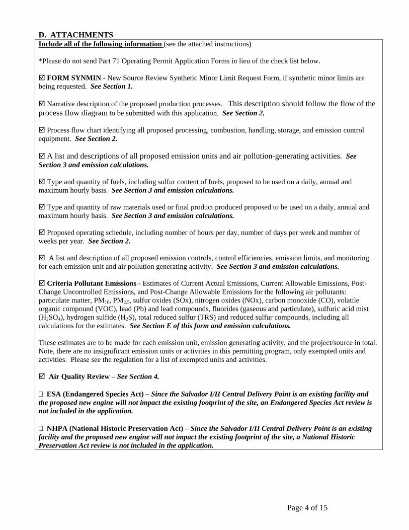
D. ATTACHMENTS Include all of the following information (see the attached instructions) *Please do not send Part 71 Operating Permit Application Forms in lieu of the check list below. FORM SYNMIN - New Source Review Synthetic Minor Limit Request Form, if synthetic minor limits are being requested. See Section 1. Narrative description of the proposed production processes. This description should follow the flow of the process flow diagram to be submitted with this application. See Section 2. Process flow chart identifying all proposed processing, combustion, handling, storage, and emission control equipment. See Section 2. A list and descriptions of all proposed emission units and air pollution-generating activities. See Section 3 and emission calculations. Type and quantity of fuels, including sulfur content of fuels, proposed to be used on a daily, annual and maximum hourly basis. See Section 3 and emission calculations. Type and quantity of raw materials used or final product produced proposed to be used on a daily, annual and maximum hourly basis. See Section 3 and emission calculations. Proposed operating schedule, including number of hours per day, number of days per week and number of weeks per year. See Section 2. A list and description of all proposed emission controls, control efficiencies, emission limits, and monitoring for each emission unit and air pollution generating activity. See Section 3 and emission calculations. Criteria Pollutant Emissions - Estimates of Current Actual Emissions, Current Allowable Emissions, Post-Change Uncontrolled Emissions, and Post-Change Allowable Emissions for the following air pollutants: particulate matter, PM10, PM2.5, sulfur oxides (SOx), nitrogen oxides (NOx), carbon monoxide (CO), volatile organic compound (VOC), lead (Pb) and lead compounds, fluorides (gaseous and particulate), sulfuric acid mist (H2SO4), hydrogen sulfide (H2S), total reduced sulfur (TRS) and reduced sulfur compounds, including all calculations for the estimates. See Section E of this form and emission calculations. These estimates are to be made for each emission unit, emission generating activity, and the project/source in total. Note, there are no insignificant emission units or activities in this permitting program, only exempted units and activities. Please see the regulation for a list of exempted units and activities. Air Quality Review – See Section 4.
ESA (Endangered Species Act) – Since the Salvador I/II Central Delivery Point is an existing facility and the proposed new engine will not impact the existing footprint of the site, an Endangered Species Act review is not included in the application.
NHPA (National Historic Preservation Act) – Since the Salvador I/II Central Delivery Point is an existing facility and the proposed new engine will not impact the existing footprint of the site, a National Historic Preservation Act review is not included in the application.
Page 5 of 15
E. TABLE OF ESTIMATED EMISSIONS The following tables provide the total emissions in tons/year for all pollutants from the calculations required in Section D of this form, as appropriate for the use specified at the top of the form. E(i) – Proposed New Source*
Pollutant Potential Emissions (tpy)
Proposed Allowable Emissions
(tpy)
PM - Particulate Matter PM10 - Particulate Matter less than 10 microns in size PM2.5 - Particulate Matter less than 2.5 microns in size SO2 - Sulfur Oxides NOx - Nitrogen Oxides CO - Carbon Monoxide VOC - Volatile Organic Compound Pb - Lead and lead compounds Fluorides - Gaseous and particulates H2SO4 - Sulfuric Acid Mist H2S - Hydrogen Sulfide TRS - Total Reduced Sulfur RSC - Reduced Sulfur Compounds
PM
PM10 PM 2.5 SO2
NOx CO
VOC Pb
Fluorides H2SO4
H2S TRS RSC
*This application is for proposed construction of new equipment at an existing synthetic minor source and for establishing legally and practically enforceable limitations and requirements on new and existing equipment at an existing synthetic minor source. Emissions calculations must include fugitive emissions if the source is one the following listed sources, pursuant to CAA Section 302(j): Fugitive emissions are not required to be included since the source is not one of the following listed sources. (a) Coal cleaning plants (with thermal dryers); (b) Kraft pulp mills; (c) Portland cement plants; (d) Primary zinc smelters; (e) Iron and steel mills; (f) Primary aluminum ore reduction plants; (g) Primary copper smelters; (h) Municipal incinerators capable of charging more than
250 tons of refuse per day; (i) Hydrofluoric, sulfuric, or nitric acid plants; (j) Petroleum refineries; (k) Lime plants; (l) Phosphate rock processing plants; (m) Coke oven batteries; (n) Sulfur recovery plants; (o) Carbon black plants (furnace process); (p) Primary lead smelters; (q) Fuel conversion plants;
(r) Sintering plants; (s) Secondary metal production plants; (t) Chemical process plants (u) Fossil-fuel boilers (or combination thereof) totaling
more than 250 million British thermal units per hour heat input;
(v) Petroleum storage and transfer units with a total storage capacity exceeding 300,000 barrels;
(w) Taconite ore processing plants; (x) Glass fiber processing plants; (y) Charcoal production plants; (z) Fossil fuel-fired steam electric plants of more that
250 million British thermal units per hour heat input, and
(aa) Any other stationary source category which, as of August 7, 1980, is being regulated under section 111 or 112 of the Act.
Page 6 of 15
E(ii) – Proposed New Construction at an Existing Source or Modification of an Existing Source* Pollutant Current
NOx 78.36 89.76 103.68 111.31 CO 95.97 103.37 150.20 84.46
VOC 47.33 49.09 65.31 65.31 Pb
Fluorides H2SO4
H2S TRS RSC
* This application is for proposed construction of new equipment at an existing synthetic minor source and for establishing legally and practically enforceable limitations and requirements on new and existing equipment at an existing synthetic minor source. The values in the above table represent total site emissions. BP is requesting federally enforceable limits for existing equipment (Emission Unit 2, which are 0.64 lb/hr CO; 0.32 lb/hr CH2O) and for new equipment (Emission Unit 5, which are: 1.03 lb/hr CO; 0.46 lb/hr CH2O). The facility-wide potential to emit (post-change allowable emissions) is not federally enforceable. **The current actual emissions are based on the actual emissions of the units in operation at the Salvador CDP during the preceding 2014 calendar year. The current allowable emissions represent the site totals with the Unit 2 engine replacement. Post-change potential emissions include the potential uncontrolled emissions from the proposed project in the site total. PM - Particulate Matter PM10 - Particulate Matter less than 10 microns in size PM2.5 - Particulate Matter less than 2.5 microns in size SO2 - Sulfur Oxides NOx - Nitrogen Oxides CO - Carbon Monoxide VOC - Volatile Organic Compound Pb - Lead and lead compounds Fluorides - Gaseous and particulates H2SO4 - Sulfuric Acid Mist H2S - Hydrogen Sulfide TRS - Total Reduced Sulfur RSC - Reduced Sulfur Compounds
The public reporting and recordkeeping burden for this collection of information is estimated to average 20 hours per response, unless a modeling analysis is required. If a modeling analysis is required, the public reporting and recordkeeping burden for this collection of information is estimated to average 60 hours per response .Send comments on the Agency’s need for this information, the accuracy of the provided burden estimates, and any suggested methods for minimizing respondent burden, including through the use of automated collection techniques to the Director, Collection Strategies Division, U.S. Environmental Protection Agency (2822T), 1200 Pennsylvania Ave., NW, Washington, D.C. 20460. Include the OMB control number in any correspondence. Do not send the completed form to this address.
Salvador I/II Central Delivery Point 1-3 BP America Production Company August 2015, rev Oct 2015 TRIBAL MNSR SYNTHETIC MINOR PERMIT APPLICATION
2 – Form SYNMIN
OMB Control No. Pending
UNITED STATES ENVIRONMENTAL PROTECTION AGENCY FEDERAL MINOR NEW SOURCE REVIEW PROGRAM IN INDIAN COUNTRY
40 CFR 49.151
Application For Synthetic Minor Limit (Form SYNMIN)
Use of this information request form is voluntary and not yet approved by the Office of Management and Budget. The following is a check list of the type of information that Region 8 will use to process information on your proposed project. While submittal of this form is not required, it does offer details on the information we will use to complete your requested approval and providing the information requested may help expedite the process. Use of application forms for this program is currently under Office of Management and Budget review and these information request forms will be replaced/updated after that review is completed.
Please submit information to following two entities:
Federal Minor NSR Permit Coordinator U.S. EPA, Region 8 1595 Wynkoop Street, 8P-AR Denver, CO 80202-1129 [email protected] For more information, visit: http://www2.epa.gov/region8/tribal-minor-new-source-review-permitting
The Tribal Environmental Contact for the specific reservation: If you need assistance in identifying the appropriate Tribal Environmental Contact and address, please contact: [email protected]
A. GENERAL INFORMATION Company Name (Who owns this facility?) BP America Production Company
Facility Name Salvador I/II Central Delivery Point
Company Contact (Who is the primary contact for the company that owns this facility?) Devin Newby
Title Area Manager, Midstream
Mailing Address 380 Airport Road, Durango, CO 81303 Email Address [email protected] Telephone Number (970) 394-4815
Facsimile Number
B. ATTACHMENTS
For each criteria air pollutant, hazardous air pollutant and for all emission units and air pollutant-generating activities to be covered by a limitation, include the following: Item 1 - The proposed limitation and a description of its effect on current actual, allowable and the potential to emit. See Section 3 and emission calculations. Item 2 - The proposed testing, monitoring, recordkeeping, and reporting requirements to be used to demonstrate and assure compliance with the proposed limitation. See Section 3. Item 3 - A description of estimated efficiency of air pollution control equipment under present or anticipated operating conditions, including documentation of the manufacturer specifications and guarantees. See Section 3 and emission calculations. Item 4 - Estimates of the Post-Change Allowable Emissions that would result from compliance with the proposed limitation, including all calculations for the estimates. See Section 3 and emission calculations. Item 5 – Estimates of the potential emissions of Greenhouse Gas (GHG) pollutants. See Section 3 and emission calculations.
Salvador I/II Central Delivery Point 2-1 BP America Production Company August 2015, rev Oct 2015 TRIBAL MNSR SYNTHETIC MINOR PERMIT APPLICATION
2 FACILITY INFORMATION
2.1 Process and Product Description The Salvador I/II Central Delivery Point is a natural gas compression facility located in southwestern Colorado. The Salvador I portion of the facility is located on fee land and the Salvador II portion is located on trust land within the exterior boundary of the Southern Ute Indian Reservation. The Salvador I/II Central Delivery Point provides natural gas field compression. Upstream of the facility are Fruitland Gas (coal bed methane) wells which are connected to a gathering pipeline system and the inlet of the facility. The Salvador Gas Unit A #1 wellsite is located within the fence line of the facility, and the wellsite natural gas commingles with the field gas coming into the facility and passes through one inlet separator. The commingled natural gas composition is primarily methane. In addition, the gas contains some carbon dioxide and is saturated with water vapor. No condensate or natural gas liquids are produced. Free liquid water, water vapor, and entrained lubricating oil are removed from the gas, and the gas is compressed and sent on to third party or BP-owned gathering systems. 2.2 Process Flow Diagram A simplified process flow diagram of the Salvador I/II Central Delivery Point is included in the application and includes the proposed new engine and proposed control equipment. 2.3 Operating Schedule The proposed operating schedule for each of the affected emission units is twenty-four (24) hours per day, seven (7) days per week, and fifty-two (52) weeks per year. Emission calculations are based on 8,760 hours of operation per year.
SECTION
Salvador I/II Central Delivery Point BP America Production Company August 2015, rev Oct 2015 TRIBAL MNSR SYNTHETIC MINOR PERMIT APPLICATION
2-2
3 – Simplified Process Flow Diagram
Salvador I/II Central Delivery PointSimplified Process Flow Diagram
Salvador Gas Unit A #1 Well
Produced gas from field
Produced gas from field
Separator
Water to tanks
1,334 hp 4SLB Compressor Engine
w/Oxicat (Unit 1)
1,874 hp 4SLB Compressor Engine
w/Oxicat(Proposed Unit 5)
1,138 hp 4SLB Compressor Engine w/proposed Oxicat
(Unit 2)
1,334 hp 4SLB Compressor Engine
(Unit 3)
1,467 4SRB Compressor Engine w/NSCR & AFRC
(Unit 4)
45 MMscfd TEG Dehydration Unit
Gas to and from third party
Gas from third party
Rich glycol
Electric heating unit
Lean glycol
Fuel for site
Gas leaving siteTo BP or third
party sites
Gas Gas
Note: The site also includes emissions from tank heaters, separator heaters, and various storage tanks.
Salvador I/II Central Delivery Point 3-1 BP America Production Company August 2015, rev Oct 2015 TRIBAL MNSR SYNTHETIC MINOR PERMIT APPLICATION
3 AFFECTED EMISSION UNITS
3.1 Affected Emission Units and Emission Calculations BP is submitting this minor New Source Review (mNSR) permit application to construct the proposed Emission Unit 5 at the Salvador I/II Central Delivery Point, which is an existing synthetic minor source permitted under Permit #SMNSR-SU-000009-2012.002, and to establish federally enforceable CO and CH2O emission limits for Emission Unit 2 and Emission Unit 5. Emission Unit 2 is a 1,138, or lower, hp four-stroke lean burn (4SLB) compressor engine with proposed oxidation catalyst controls. Emission Unit 5 is a proposed 1,874, or lower, hp 4SLB compressor engine with oxidation catalyst controls. Potential-to-emit calculations, including greenhouse gases and controlled and uncontrolled emissions from Emission Unit IDs Unit 2 and Unit 5, and current actual emissions for the preceding calendar year are included in the application. Since the facility does not belong to one of the source categories listed in 40 CFR 52.21(b)(1)(iii), fugitive emissions are not included in the potential-to-emit calculations. Estimates of actual emissions are calculated for Emission Unit IDs Unit 1, Unit 2, Unit 3, and Unit 4 for the previous 2014 calendar year. Actual emissions for Unit 2 are based on the 666 hp 4SLB compressor engine that was in operation in 2014. BP is planning to replace this unit with the 1,138, or lower, hp 4SLB compressor engine in October 2015. 3.2 Identification and Description of Existing Air Pollution Control Equipment and Requested Synthetic Minor Limits For Emission Unit 2, BP is proposing to install an oxidation catalyst capable of reducing uncontrolled emissions of carbon monoxide (CO) emissions by at least 90% and formaldehyde (CH2O) emissions by at least 55% at a maximum operating rate (90% to 110% of engine capacity at site elevation). The requested permit limits are 0.64 lb/hr CO and 0.32 lb/hr CH2O for the proposed controls. The proposed Emission Unit 5 will be equipped with an oxidation catalyst capable of reducing uncontrolled emissions of CO emissions by at least 90% and CH2O emissions by at least 60% at a maximum operating rate (90% to 110% of engine capacity at site elevation). The requested permit limits are 1.03 lb/hr CO and 0.46 lb/hr CH2O. Since engineering design is not presently in detailed progress, the catalyst manufacturers and models have not been selected yet. However, the requested federally enforceable CO and CH2O limits will be met regardless of the catalyst manufacturer or model. The control efficiencies are not federally enforceable.
SECTION
Salvador I/II Central Delivery Point BP America Production Company August 2015, rev Oct 2015 TRIBAL MNSR SYNTHETIC MINOR PERMIT APPLICATION
3-2
3.3 Proposed Testing, Monitoring, Recordkeeping and Reporting Requirements In accordance with 40 CFR 49.158(a)(1)(ii)(B), BP is including proposed testing, monitoring, recordkeeping, and reporting requirements to be used to demonstrate and assure compliance with the proposed emission limitations for Emission Unit 2 and Emission Unit 5. These requirements recognize the oxidation catalyst equipment that will be installed on both engines for limiting the potential-to-emit CO and CH2O emissions. The proposed requirements are included as a Supplemental Document beginning on page 3-3 of the application. 3.4 Type and Quantity of Fuel and Raw Materials Used The affected emission units at the Salvador I/II Central Delivery Point will be fired with natural gas only. The heat content of this natural gas at the site ranges from approximately 800 – 1000 Btu/ft3. The maximum sulfur content of the gas is 1×10⁻⁷ percent. The daily, annual, and maximum hourly fuel use for each source is provided in the emission calculations.
Salvador I/II Central Delivery Point BP America Production Company August 2015, rev Oct 2015 TRIBAL MNSR SYNTHETIC MINOR PERMIT APPLICATION
The below proposed operational, testing, monitoring, recordkeeping, and reporting requirements are requested to recognize emissions control equipment on engine units Unit 2 and Unit 5 for limiting the potential-to-emit (PTE) of carbon monoxide (CO) and formaldehyde (CH2O) [40 CFR 49.155(a)(1)(iii)]. These requirements are identical to the requirements for the 1,334 hp 4SLB compressor engine in permit number SMNSR-SU-000009-2012.002 for the Salvador I/II Central Delivery Point, with the exception of the additional text in underlined italics font. Proposed Revision of Operational Requirements
(i) The Permittee may rebuild or replace an existing permitted engine with an engine of the same or lower horsepower rating, and configured to operate in the same manner as the engine being rebuilt or replaced. Any emission limits, requirements, control technologies, testing or other provisions that apply to the permitting engines that are replaced shall also apply to the rebuilt or replacement engines.
Proposed Testing Requirements
(a) Performance tests shall be conducted on the engines for measuring CO and CH2O emissions to demonstrate compliance with each emission limitation in this permit. The performance tests shall be conducted in accordance with appropriate reference methods specified in 40 CFR Part 60, Appendix A and 40 CFR Part 63, Appendix A, or an EPA-approved American Society for Testing and Materials (ASTM) method. The Permittee may submit to the EPA a written request for approval of an alternate test method, but shall only use that alternate test method after obtaining approval from the EPA. (i) The initial performance test shall be conducted within 90 calendar days of startup of a
new engine. (ii) Subsequent performance tests for CH2O emissions shall be conducted on the engines
within 12 months of the most recent performance test. (iii) Performance tests shall be conducted within 90 calendar days of the initial installation
or replacement of the catalyst on each engine. (iv) Performance tests shall be conducted within 90 calendar days of startup of all rebuilt
and replacement engines.
(b) The Permittee shall not perform engine tuning or make any adjustments to engine settings, catalytic control system settings, processes, or operational parameters the day of or during the engine testing. Any such tuning or adjustments may result in a determination by the EPA that the test is invalid. Artificially increasing an engine load to meet test requirements is not considered engine tuning or adjustments.
(c) The Permittee shall not abort any engine tests that demonstrate non-compliance with any CO or CH2O emission limits in this permit.
(d) Performance tests conducted on the engines for measuring CO and CH2O emissions shall
meet the following requirements:
(i) The pressure drop across each catalyst bed and the inlet temperature to each catalyst bed shall be measured and recorded at least once per test during all performance tests.
2 of 7
(ii) The Permittee shall measure NOx emissions from the engines simultaneously with all performance tests for CO emissions. NOx emissions shall be measured using a portable analyzer and protocol approved in writing by the EPA. [Note to Permittee: Although the permit does not contain NOx emission limits for this engine, NOx measurement requirements have been included as an indicator to ensure compliance with Condition C.4(b) above.]
(iii) All performance tests shall be conducted at maximum operating rate (90% to 110% of the maximum achievable load available at the time of the test). The Permittee may submit to the EPA a written request for approval of an alternate load level for testing, but shall only test at that alternate load level after obtaining written approval from the EPA.
(iv) During each test run, data shall be collected on all parameters necessary to document how emissions were measured and calculated (such as test run length, minimum sample volume, volumetric flow rate, moisture and oxygen corrections, etc.).
(v) Each test shall consist of at least three 1-hour or longer valid test runs. Emission results shall be reported as the arithmetic average of all valid test runs and shall be in terms of the emission limits in this permit.
(vi) Performance test plans shall be submitted to the EPA for approval 60 calendar days prior to the date the test is planned.
(vii) Performance test plans that have already been approved by the EPA for the emission units approved in this permit or for similar emission units approved in another BP permit may be used in lieu of new test plans unless the EPA requires the submittal and approval of new test plans. The Permittee may submit new plans for EPA approval at any time.
(viii) The test plans shall include and address the following elements: (A) Purpose of the test; (B) Engines and catalytic control systems to be tested; (C) Expected engine operating rate(s) during the test; (D) Sampling and analysis procedures (sampling locations, test methods,
laboratory identification); (E) Quality assurance plan (calibration procedures and frequency, sample
recovery and field documentation, chain of custody procedures); and (F) Data processing and reporting (description of data handling and quality control
procedures, report content).
(e) The Permittee shall notify the EPA at least 30 calendar days prior to scheduled performance testing. The Permittee shall notify the EPA at least 1 week prior to scheduled performance testing if the testing cannot be performed.
(f) If the results of a complete and valid performance test of the emissions from any permitted engine demonstrate noncompliance with the emission limits in this permit, the engine shall be shut down as soon as safely possible, and appropriate corrective action shall be taken (e.g., repairs, catalyst cleaning, catalyst replacement). The Permittee shall notify the EPA in writing within 24 hours of each such shut down. The engine must be retested within 7 days of being restarted and the emissions must meet the applicable limits in this permit. If the retest shows that the emissions continue to exceed the limits in this permit, the engine shall again be shut down as soon as safely possible, and the engine may not operate, except for purposes of startup and testing, until the Permittee demonstrates through testing that the emissions do not exceed the emission limits in this permit.
3 of 7
(g) If a permitted engine is not operating, the Permittee does not need to start up the engine solely to conduct a performance test. The Permittee may conduct the performance test when the engine is started up again.
(a) The Permittee shall continuously monitor the engine exhaust temperature at the inlet to the catalyst bed on each engine.
(b) Except during startups, which shall not exceed 30 minutes, if the engine’s exhaust temperature at the inlet to the catalyst bed on any one (1) engine deviates from the acceptable ranges specified in this permit then the following actions shall be taken. The Permittee’s completion of any or all of these actions shall not constitute, nor qualify as, an exemption from any other emission limits in this permit.
(i) Within 24 hours of determining a deviation of the engine exhaust temperature at the
inlet to the catalyst bed, the Permittee shall investigate. The investigation shall include testing the temperature sensing device, inspecting the engine for performance problems and assessing the catalytic control system for possible damage that could affect catalytic system effectiveness (including, but not limited to, catalyst housing damage, and fouled, destroyed or poisoned catalyst).
(ii) If the engine exhaust temperature at the inlet to the catalyst bed can be corrected by following the engine manufacturer recommended procedures or equivalent procedures developed by the Permittee or vendor and the catalytic control system has not been damaged, then the Permittee shall correct the engine exhaust temperature at the inlet to the catalyst bed within 24 hours of inspecting the engine and catalytic control system.
(iii) If the engine exhaust temperature at the inlet to the catalyst bed cannot be corrected
using the engine manufacturer recommended procedures or equivalent procedures developed by the Permittee or vendor, or the catalytic control system has been damaged, then the affected engine shall cease operating immediately and shall not be returned to routine service until the following has been met: (A) The engine exhaust temperature at the inlet to the catalyst bed is measured and
found to be within the acceptable temperature range for that engine; and (B) The catalytic control system has been repaired or replaced, if necessary.
(c) The Permittee shall monitor the pressure drop across the catalyst bed on each engine every 30 days using pressure sensing devices before and after the catalyst bed to obtain a direct reading of the pressure drop (also referred to as the differential pressure). [Note to Permittee: Differential pressure measurements, in general, are used to show the pressure across the filter elements. This information will determine when the elements in the catalyst bed are fouling, blocked or blown out and thus require cleaning or replacement.]
(d) The Permittee shall perform the first measurement of the pressure drop across the catalyst bed on each engine no more than 30 days from the date of the initial performance test. Thereafter, the Permittee shall measure the pressure drop across the catalyst bed, at a minimum every 30 days. Subsequent performance tests, as required in this permit, can be used to meet the periodic pressure drop monitoring requirement provided it occurs within the
4 of 7
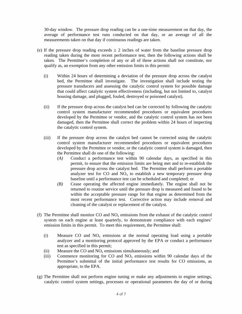
30-day window. The pressure drop reading can be a one-time measurement on that day, the average of performance test runs conducted on that day, or an average of all the measurements taken on that day if continuous readings are taken.
(e) If the pressure drop reading exceeds ± 2 inches of water from the baseline pressure drop
reading taken during the most recent performance test, then the following actions shall be taken. The Permittee’s completion of any or all of these actions shall not constitute, nor qualify as, an exemption from any other emission limits in this permit:
(i) Within 24 hours of determining a deviation of the pressure drop across the catalyst
bed, the Permittee shall investigate. The investigation shall include testing the pressure transducers and assessing the catalytic control system for possible damage that could affect catalytic system effectiveness (including, but not limited to, catalyst housing damage, and plugged, fouled, destroyed or poisoned catalyst).
(ii) If the pressure drop across the catalyst bed can be corrected by following the catalytic control system manufacturer recommended procedures or equivalent procedures developed by the Permittee or vendor, and the catalytic control system has not been damaged, then the Permittee shall correct the problem within 24 hours of inspecting the catalytic control system.
(iii) If the pressure drop across the catalyst bed cannot be corrected using the catalytic
control system manufacturer recommended procedures or equivalent procedures developed by the Permittee or vendor, or the catalytic control system is damaged, then the Permittee shall do one of the following: (A) Conduct a performance test within 90 calendar days, as specified in this
permit, to ensure that the emission limits are being met and to re-establish the pressure drop across the catalyst bed. The Permittee shall perform a portable analyzer test for CO and NOx to establish a new temporary pressure drop baseline until a performance test can be scheduled and completed; or
(B) Cease operating the affected engine immediately. The engine shall not be returned to routine service until the pressure drop is measured and found to be within the acceptable pressure range for that engine as determined from the most recent performance test. Corrective action may include removal and cleaning of the catalyst or replacement of the catalyst.
(f) The Permittee shall monitor CO and NOx emissions from the exhaust of the catalytic control system on each engine at least quarterly, to demonstrate compliance with each engines’ emission limits in this permit. To meet this requirement, the Permittee shall: (i) Measure CO and NOx emissions at the normal operating load using a portable
analyzer and a monitoring protocol approved by the EPA or conduct a performance test as specified in this permit;
(ii) Measure the CO and NOx emissions simultaneously; and (iii) Commence monitoring for CO and NOx emissions within 90 calendar days of the
Permittee’s submittal of the initial performance test results for CO emissions, as appropriate, to the EPA.
(g) The Permittee shall not perform engine tuning or make any adjustments to engine settings,
catalytic control system settings, processes or operational parameters the day of or during
5 of 7
measurements. Any such tuning or adjustments may result in a determination by the EPA that the result is invalid. Artificially increasing an engine load to meet testing requirements is not considered engine tuning or adjustments.
(h) For any one (1) engine: If the results of consecutive quarterly portable analyzer measurements demonstrate compliance with the CO emission limits, the required monitoring frequency may change from quarterly to semi-annually.
(i) For any one (1) engine: If the results of consecutive semi-annual portable analyzer measurements demonstrate non-compliance with the CO emission limits, the required test frequency shall revert back to quarterly.
(j) The Permittee shall submit portable analyzer specifications and monitoring protocols to the
EPA at the following address for approval at least 45 calendar days prior to the date of initial portable analyzer monitoring:
U.S. Environmental Protection Agency, Region 8 Office of Enforcement, Compliance & Environmental Justice Air Toxics and Technical Enforcement Program, 8ENF-AT 1595 Wynkoop Street Denver, Colorado 80202 The protocol may be submitted via electronic mail to [email protected].
(k) Portable analyzer specifications and monitoring protocols that have already been approved by
the EPA for the emission units approved in this permit or for similar emission units approved in another BP permit may be used in lieu of new protocols unless the EPA determines it is necessary to require the submittal and approval of a new protocol. The Permittee may submit a new protocol for EPA approval at any time.
(l) The Permittee is not required to conduct emissions monitoring and parametric monitoring of exhaust temperature and catalyst differential pressure on engines that have not operated during the monitoring period. The Permittee shall certify that the engine(s) did not operate during the monitoring period in the annual report.
(a) Records shall be kept of manufacturer and/or vendor specifications and maintenance requirements developed by the manufacturer, vendor, or Permittee for each engine, catalytic control system, temperature-sensing device, and pressure-measuring device.
(b) Records shall be kept of all calibration and maintenance conducted for each engine, catalytic
control system, temperature-sensing device, and pressure-measuring device.
(c) Records shall be kept that are sufficient to demonstrate that the fuel for each engine is pipeline quality natural gas in all respects, with the exception of CO2 concentrations.
(d) Records shall be kept of all temperature measurements required in this permit, as well as a
description of any corrective actions taken pursuant to this permit.
6 of 7
(e) Records shall be kept of all pressure drop measurements required in this permit, as well as a
description of any corrective actions taken pursuant to this permit. (f) Records shall be kept of all required testing and monitoring in this permit. The records shall
include the following:
(i) The date, place, and time of sampling or measurements; (ii) The date(s) analyses were performed; (iii) The company or entity that performed the analyses; (iv) The analytical techniques or methods used; (v) The results of such analyses or measurements; and (vi) The operating conditions as existing at the time of sampling or measurement.
(g) Records shall be kept of all catalyst replacements or repairs, engine rebuilds, and
replacements. (h) Records shall be kept of each rebuilt or replacement engine break-in period, pursuant to the
requirements of this permit, where an existing engine that has been rebuilt or replaced resumes operation without the catalyst control system, for a period not to exceed 200 hours.
(i) Records shall be kept of each time any engine is shut down due to a deviation in the inlet
temperature to the catalyst bed or pressure drop across a catalyst bed. The Permittee shall include in the record the cause of the problem, the corrective action taken, and the timeframe for bringing the pressure drop and inlet temperature range into compliance.
Requirements for Records Retention
(a) The Permittee shall retain all records required by this permit for a period of at least 5 years from the date the record was created.
(b) Records shall be kept in the vicinity of the facility, such as at the facility, the location that has day-to-day operational control over the facility, or the location that has day-to-day responsibility for compliance of the facility.
(a) The Permittee shall submit a written annual report of the actual annual emissions from all emission units at the facility covered under this permit, including emissions from startups, shutdowns, and malfunctions, each year no later than April 1st. The annual report shall cover the period for the previous calendar year. All reports shall be certified to truth and accuracy by the person primarily responsible for Clean Air Act compliance for the Permittee.
(b) The report shall include CO and CH2O emissions.
(c) The report shall be submitted to:
U.S. Environmental Protection Agency, Region 8
7 of 7
Office of Partnerships and Regulatory Assistance Tribal Air Permitting Program, 8P-AR 1595 Wynkoop Street Denver, Colorado 80202
The report may be submitted via electronic mail to [email protected].
2. All other documents required to be submitted under this permit, with the exception of the
Annual Emission Reports, shall be submitted to: U.S. Environmental Protection Agency, Region 8 Office of Enforcement, Compliance & Environmental Justice Air Toxics and Technical Enforcement Program, 8ENF-AT 1595 Wynkoop Street Denver, Colorado 80202
3. The Permittee shall promptly submit to the EPA a written report of any deviations of permit requirements, a description of the probable cause of such deviations, and any corrective actions or preventative measures taken. A “prompt” deviation report is one that is post marked or submitted via electronic mail to [email protected] as follows:
(a) Within 30 days from the discovery of any deviation of the emission limits or operational limits that is left un-corrected for more than 5 days after discovering the deviation;
(b) By April 1st for the discovery of a deviation of recordkeeping or other permit conditions during the preceding calendar year that do not affect the Permittee’s ability to meet the emission or operational limits.
4. The Permittee shall submit a written report for any required performance tests to the EPA
Regional Office within 60 days after completing the tests. 5. The Permittee shall submit any record or report required by this permit upon EPA request.
Salvador I/II Central Delivery Point BP America Production Company August 2015, rev Oct 2015 TRIBAL MNSR SYNTHETIC MINOR PERMIT APPLICATION
3-4
5 – Potential-to-Emit Emission Calculations and Supporting Documentation
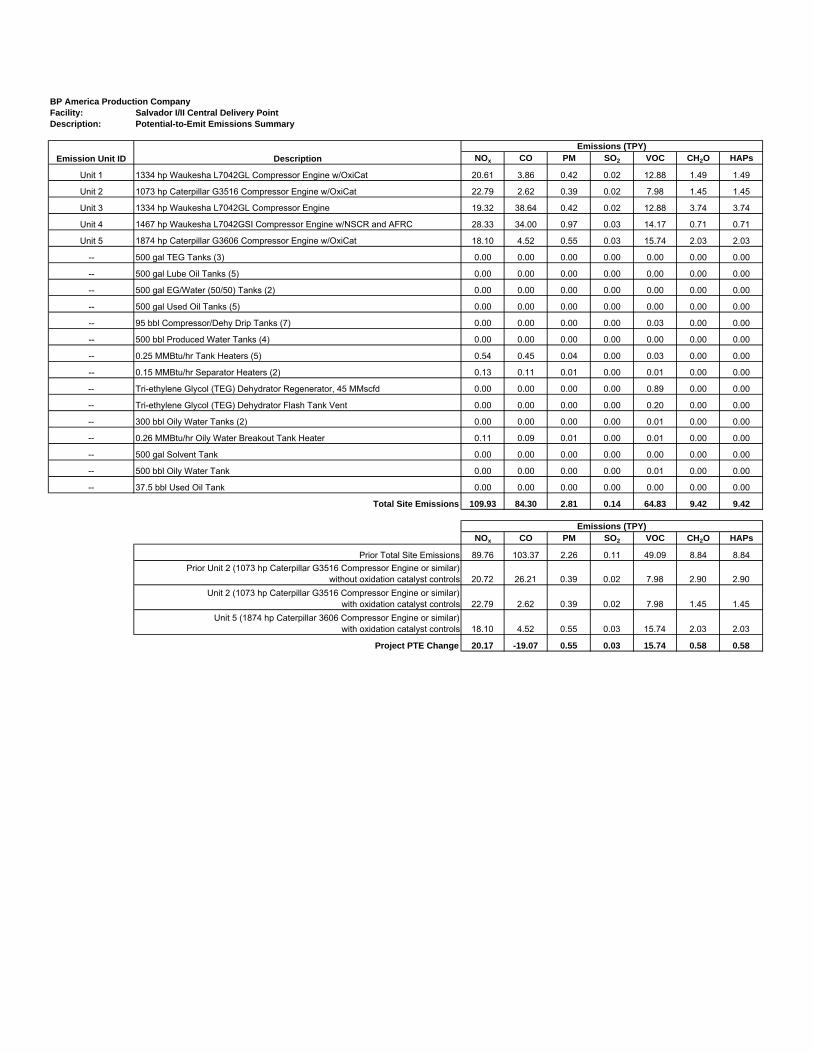
BP America Production CompanyFacility: Salvador I/II Central Delivery PointDescription: Potential-to-Emit Emissions Summary
NOx CO PM SO2 VOC CH2O HAPs
Unit 1 1334 hp Waukesha L7042GL Compressor Engine w/OxiCat 20.61 3.86 0.42 0.02 12.88 1.49 1.49
Unit 2 1138 hp Caterpillar G3516 Compressor Engine w/OxiCat 24.17 2.78 0.42 0.02 8.46 1.38 1.38
Unit 3 1334 hp Waukesha L7042GL Compressor Engine 19.32 38.64 0.42 0.02 12.88 3.74 3.74
Unit 4 1467 hp Waukesha L7042GSI Compressor Engine w/NSCR and AFRC 28.33 34.00 0.97 0.03 14.17 0.71 0.71
Unit 5 1874 hp Caterpillar G3606 Compressor Engine w/OxiCat 18.10 4.52 0.55 0.03 15.74 2.03 2.03
Example Calculations:NOX Emissions (lb/hr) = 1138 hp * 2.00 g/hp-hr * lb/453.6 g = 5.02NOX Emissions (TPY) = 5.02 lb/hr * 8760 hr/yr * 1 Ton/2000 lb = 21.98
[1] Based on LEHW0036-00 for Caterpillar G3516 DM8620-01, 1200 rpm, 130 oF aftercooler water inlet, TA aspiration, maximum rating. Site rating based on deducting 3% for every 1000 feet above 6000 feet. Horsepower from this engine configuration is being used as it results in the highest potential emissions.
[3] Conservatively based on full time operating hours and full capacity.[4] Heat input based on fuel consumption and site-rated HP. Fuel usage rates based on fuel consumption x site-rated hp / 800 Btu/scf conservative heating value.
[6] Based on AP-42, Fifth Edition, Volume 1, Chapter 3, Section 3.2, Table 3.2-2 Uncontrolled Emission Factors For 4-Stroke Lean-Burn Engines, 7/00. PM emission factor is the sum of PMfilterable and PMcondensable.
[5] In BP's experience with the combustion of oxidation catalysts, there is a slight increase in the NO x
emission factor. The manufacturer emission factor for NOx, 2.00 g/hp-hr, has been increased to 2.20 g/hp-hr to account for the oxidation catalyst. If actual emissions are determined to be higher, BP will update the potential-to-emit calculations with an updated factor.
[7] BP's lb/hr limits assume a 90% reduction in CO and a 55% reduction of CH2O at full load. Although the engine may operate at loads other than 100%, the lb/hr limits will be met at any load. The control efficiencies are not federally enforceable. An engine CO limit of 0.64 lb/hr and a CH2O limit of 0.32 lb/hr are enforceable.
[2] Based on Caterpillar Gas Engine Rating Pro Version 5.02.01 (Ref. Data Set DM0107-09-001) for Caterpillar G3516, 1200 rpm, 8:1 CR, 130 oF aftercooler water inlet, TA aspiration, maximum rating. Emission factors and fuel consumption from this engine configuration are being used as they result in the highest potential emissions and heat input. VOC emission factor is the sum of the NMNEHC and CH2O emission factors.
BP America Production CompanyFacility: Salvador I/II Central Delivery Point
Description: 1874 hp Four-Stroke Lean Burn Engine[1]
[6] Based on the 2011 results of formaldehyde testing of Caterpillar 3606 engines located at BP sites in Colorado. Although the manufacturer factor for CH2O is 0.26 g/hp-hr, the uncontrolled factor has been increased to 0.28 g/hp-hr.[7] BP's lb/hr limits assume a 90% reduction in CO and a 60% reduction in CH2O at full load. Although the engine may operate
at loads other than 100%, the lb/hr emission limits will still be met. The control efficiencies are not federally enforceable. An engine CO limit of 1.03 lb/hr and a CH2O limit of 0.46 lb/hr are enforceable.
[1] Based on Caterpillar Gas Engine Rating Pro Version 5.04.00 (Ref. Data Set DM5432-08-001) for Caterpillar G3606, 1000 rpm, 9.2:1 CR, 90 oF aftercooler water inlet, TA aspiration. Site rating based on deducting 3% for every 1000 feet above 6000 feet. The VOC emission factor is the sum of the NMNEHC and CH2O emission factors.[2] Conservatively based on full time operating hours and full capacity.
[4] In BP's experience with the combustion of oxidation catalysts, there is a slight increase in the NOx emission factor. For
controlled emissions, the emission factor for NOx has been increased to 1.0 g/hp-hr to account for the oxidation catalyst.
[3] Heat input based on fuel consumption and site-rated HP. Fuel usage rates based on fuel consumption x site-rated hp / 800 Btu/scf conservative heating value.
[5] Based on AP-42, Fifth Edition, Volume 1, Chapter 3, Section 3.2, Table 3.2-2 Uncontrolled Emission Factors For 4-Stroke Lean-Burn Engines, 7/00. PM emission factor is the sum of PMfilterable and PMcondensable.
BP America Production CompanyFacility: Salvador I/II Central Delivery PointDescription: Potential-to-Emit Greenhouse Gas Emissions Summary
CO2 CH4 N2O CO2e
Unit 1 1334 hp Waukesha L7042GL Compressor Engine w/OxiCat 4,886.6770 0.0922 0.0092 4,891.7278
Unit 2 1138 hp Caterpillar G3516 Compressor Engine w/OxiCat 4,887.8449 0.0921 0.0092 4,892.8931
Unit 3 1334 hp Waukesha L7042GL Compressor Engine 4,886.6770 0.0922 0.0092 4,891.7278
Unit 4 1467 hp Waukesha L7042GSI Compressor Engine w/NSCR and AFRC 5,858.3172 0.1105 0.0110 5,864.3722
Unit 5 1874 hp Caterpillar G3606 Compressor Engine w/OxiCat 6,472.4634 0.1220 0.0122 6,479.1481
-- 500 gal TEG Tanks (3) 0.0000 0.0000 0.0000 0.0000
[1] Based on Caterpillar Gas Engine Rating Pro Version 4.01.00 (Ref. Data Set DM5432-06-001) for Caterpillar G3606, 1000 rpm, 9:1 CR, 90 oF aftercooler water inlet, TA aspiration. Site rating based on deducting 3% for every 1000 feet above 6000 feet. [2] Conservatively based on full time operating hours and full capacity.[3] Heat input based on fuel consumption and site-rated HP.
Fuel-specific default CO2, CH4, or N2O emission factors from Table C-1 for CO2
(Natural gas - Weighted U.S. Average) and Table C-2 for CH 4 and N2O (Natural Gas) of 40 CFR Part 98, Subpart C (kg/MMBtu)
Engine Design- Proven reliability and durability - Ability to burn a wide spectrum of gaseous fuels - Robust diesel strength design prolongs life and lowers
owning and operating costs- Broad operating speed rangeEmissionsMeets U.S. EPA Spark Ignited Stationary NSPS Emissions for 2007/8Lean Burn Engine TechnologyLean-burn engines operate with large amounts of excess air. The excess air absorbs heat during combustion reducing the combustion temperature and pressure, greatly reducing levels of NOx. Lean-burn design also provides longer component life and excellent fuel consumption.Advanced Digital Engine ManagementADEM A3 control system providing integrated ignition, speed governing, protection, and controls, including detonation-sensitive variable ignition timing. ADEM A3 has improved: user interface, display system, shutdown controls, and system diagnostics.Ease of OperationSide covers on block allow for inspection of internal componentsFull Range of AttachmentsLarge variety of factory-installed engine attachments reduces packaging timeTestingEvery engine is full-load tested to ensure proper engine performance.
Gas Engine Rating Pro GERP is a PC-based program designed to provide site performance capabilities for Cat® natural gas engines for the gas compression industry. GERP provides engine data for your site’s altitude, ambient temperature, fuel, engine coolant heat rejection, performance data, installation drawings, spec sheets, and pump curves.Product Support Offered Through Global Cat Dealer NetworkMore than 2,200 dealer outletsCat factory-trained dealer technicians service every aspect of your petroleum engineCat parts and labor warrantyPreventive maintenance agreements available for repair-before-failure optionsS•O•SSM program matches your oil and coolant samples against Caterpillar set standards to determine:- Internal engine component condition- Presence of unwanted fluids- Presence of combustion by-products- Site-specific oil change intervalOver 80 Years of Engine Manufacturing ExperienceOver 60 years of natural gas engine productionOwnership of these manufacturing processes enables Caterpillar to produce high quality, dependable products.- Cast engine blocks, heads, cylinder liners, and flywheel
housings- Machine critical components- Assemble complete engineWeb SiteFor all your petroleum power requirements, visit www.catoilandgas.cat.com.
G3516 LE GAS PETROLEUM ENGINE858-999 bkW (1150-1340 bhp)
LEHW0036-00 Page 2 of 4Supersedes LEHW6046-02
Air Inlet SystemAir cleaner — intermediate-duty with service indicatorControl SystemA3 ECUAir-fuel ratio controlCooling SystemThermostats and housingJacket water pumpAftercooler water pumpAftercooler core for sea-air atmosphereAftercooler thermostats and housingExhaust SystemWatercooled exhaust manifoldsFlywheels & Flywheel HousingsSAE No. 00 flywheelSAE No. 00 flywheel housingSAE standard rotationFuel SystemGas pressure regulatorNatural gas carburetor
Ignition SystemA3 ECUInstrumentationPL1000 Advisor panelLubrication SystemCrankcase breather — top mountedOil coolerOil filter — RHOil bypass filterOil pan — shallowOil sampling valveTurbo oil accumulatorMounting SystemRails, engine mounting — 254 mm (10 in)Protection SystemElectronic shutoff systemGas shutoff valveGeneralPaint — Cat yellowVibration damper and guard — dual 484 mm (23 in)
STANDARD EQUIPMENT
Air Inlet SystemRemote air inlet adaptersPrecleanerCharging SystemBattery chargersCharging alternatorsCooling SystemAftercooler coreThermostatic valveTemperature switchConnectionsExpansion and overflow tankWater level switch gaugeExhaust SystemFlexible fittingsElbowsFlangeFlange and exhaust expandersRain capMufflersFuel SystemLow pressure gas conversionsPropane gas valve and jet kitsFuel filterInstrumentationPL1000 communications modules
Lubrication SystemOil bypass filter removal and oil pan accessoriesSump pumpAir prelube pumpManual prelube pumpLubricating oilMounting SystemRailsVibration isolatorsPower Take-OffsFront accessory drivesAuxiliary drive shafts and pulleysFront stub shaftPulleysProtection SystemExplosion relief valves, status control box interconnect
Gas Pressure kPag (psig) 241.5-275.8 241.5-275.8 (35-40) (35-40)
*at 100% load and speed, all values are listed as not to exceed**Volatile organic compounds as defined in U.S. EPA 40 CFR 60, subpart JJJJ***ISO 3046/1
drinkwja
Highlight
drinkwja
Highlight
drinkwja
Highlight
drinkwja
Highlight
G3516 LE GAS PETROLEUM ENGINE858-999 bkW (1150-1340 bhp)
GAS PETROLEUM ENGINE
Note: General configuration not to be used for installation. See general dimension drawings for detail (drawing #289-2971).
Dimensions are in mm (inches).
DIMENSIONSLength mm (in.) 3339.3 (131.47)Width mm (in.) 1820.6 (71.68)Height mm (in.) 1863.7 (73.37)Shipping Weight kg (lb) 8015 (17,670)
3339.3 (131.47) 1820.6 (71.68)
1863.7(73.37)
01 01 01
03 03
03 03
Engine performance is obtained in accordance with SAE J1995, ISO3046/1, BS5514/1, and DIN6271/1 standards.
Transient response data is acquired from an engine/generator combination at normal operating temperature and in accordance with ISO3046/1 standard ambient conditions. Also in accordance with SAE J1995, BS5514/1, and DIN6271/1 standard reference conditions.
Conditions: Power for gas engines is based on fuel having an LHV of 33.74 kJ/L (905 Btu/cu ft) at 101 kPa (29.91 in. Hg) and 15° C (59° F). Fuel rate is based on a cubic meter at 100 kPa (29.61 in. Hg) and 15.6° C (60.1° F). Air flow is based on a cubic foot at 100 kPa (29.61 in. Hg) and 25° C (77° F). Exhaust flow is based on a cubic foot at 100 kPa (29.61 in. Hg) and stack temperature.
RATING DEFINITIONS AND CONDITIONS
Materials and specifications are subject to change without notice. The International System of Units (SI) is used in this publication.CAT, CATERPILLAR, their respective logos, ADEM, “Caterpillar Yellow” and the “Power Edge” trade dress, as well as
COOLING SYSTEM SIZING CRITERIA TOTAL JACKET WATER CIRCUIT (JW+OC) (13) Btu/min 45761
TOTAL AFTERCOOLER CIRCUIT (AC) (13)(14) Btu/min 9779
A cooling system safety factor of 0% has been added to the cooling system sizing criteria.
CONDITIONS AND DEFINITIONSEngine rating obtained and presented in accordance with ISO 3046/1, adjusted for fuel, site altitude and site inlet air temperature. 100% rating at maximum inlet air temperature is the maximum enginecapability for the specified fuel at site altitude and maximum site inlet air temperature. Maximum rating is the maximum capability at the specified aftercooler inlet temperature for the specified fuel atsite altitude and reduced inlet air temperature. Lowest load point is the lowest continuous duty operating load allowed. No overload permitted at rating shown.
For notes information consult page three.
tanorl
Highlight
tanorl
Highlight
tanorl
Highlight
tanorl
Highlight
tanorl
Highlight
tanorl
Highlight
tanorl
Highlight
tanorl
Highlight
tanorl
Highlight
tanorl
Highlight
tanorl
Highlight
tanorl
Highlight
tanorl
Highlight
tanorl
Highlight
tanorl
Highlight
tanorl
Highlight
G3516 GAS ENGINE SITE SPECIFIC TECHNICAL DATANON-CURRENTGAS COMPRESSION APPLICATION
Note: At site conditions of 6360 ft and 100°F inlet air temp., constant torque can be maintained down to 1100 rpm.The minimum speed for loading at these conditions is 900 rpm.
PREPARED BY:Data generated by Gas Engine Rating Pro Version 5.02.01Ref. Data Set DM0107-09-001, 4EK, Printed 18Jun2015 Page 2 of 4
G3516 GAS ENGINE SITE SPECIFIC TECHNICAL DATANON-CURRENTGAS COMPRESSION APPLICATION
NOTES1. Engine rating is with two engine driven water pumps. Tolerance is ± 3% of full load.
2. Fuel consumption tolerance is ± 3.0% of full load data.
3. Air flow value is on a 'wet' basis. Flow is a nominal value with a tolerance of ± 5 %.
4. Inlet and Exhaust Restrictions must not exceed A&I limits based on full load flow rates from the standard technical data sheet.
5. Inlet manifold pressure is a nominal value with a tolerance of ± 5 %.
6. Exhaust temperature is a nominal value with a tolerance of (+)63°F, (-)54°F.
7. Exhaust flow value is on a "wet" basis. Flow is a nominal value with a tolerance of ± 6 %.
8. Emissions data is at engine exhaust flange prior to any after treatment.
9. Emission values are based on engine operating at steady state conditions, adjusted to the specified NOx level at 100% load. Fuel methane number cannot vary more than ± 3.NOx values are set points and will vary with operating conditions. All other emission values listed are higher than nominal levels to allow for instrumentation, measurement, andengine-to-engine variations. They indicate "Not to Exceed" values. THC, NMHC, and NMNEHC do not include aldehydes. Part load data may require engine adjustment.
10. VOCs - Volatile organic compounds as defined in US EPA 40 CFR 60, subpart JJJJ
11. Exhaust Oxygen level is the result of adjusting the engine to operate at the specified NOx level. Tolerance is ± 0.5.
12. Heat rejection values are nominal. Tolerances, based on treated water, are ± 10% for jacket water circuit, ± 50% for radiation, ± 20% for lube oil circuit, and ± 5% for aftercoolercircuit.
13. Aftercooler heat rejection includes an aftercooler heat rejection factor for the site elevation and inlet air temperature specified. Aftercooler heat rejection values at part load arefor reference only. Do not use part load data for heat exchanger sizing.
14. Cooling system sizing criteria are maximum circuit heat rejection for the site, with applied tolerances.
PREPARED BY:Data generated by Gas Engine Rating Pro Version 5.02.01Ref. Data Set DM0107-09-001, 4EK, Printed 18Jun2015 Page 3 of 4
CONDITIONS AND DEFINITIONSCONDITIONS AND DEFINITIONSCONDITIONS AND DEFINITIONSCONDITIONS AND DEFINITIONSCaterpillar Methane Number represents the knock resistance of a gaseous fuel. It should be used with the Caterpillar Fuel Usage Guide for the engine and rating to determine the rating for the fuelspecified. A Fuel Usage Guide for each rating is included on page 2 of its standard technical data sheet.
RPC always applies to naturally aspirated (NA) engines, and turbocharged (TA or LE) engines only when they are derated for altitude and ambient site conditions.
Project specific technical data sheets generated by the Caterpillar Gas Engine Rating Pro program take the Caterpillar Methane Number and RPC into account when generating a site rating.
Fuel properties for Btu/scf calculations are at 60F and 14.696 psia.
Caterpillar shall have no liability in law or equity, for damages, consequently or otherwise, arising from use of program and related material or any part thereof.
FUEL LIQUIDSFUEL LIQUIDSFUEL LIQUIDSFUEL LIQUIDSField gases, well head gases, and associated gases typically contain liquid water and heavy hydrocarbons entrained in the gas. To prevent detonation and severe damage to the engine, hydrocarbonliquids must not be allowed to enter the engine fuel system. To remove liquids, a liquid separator and coalescing filter are recommended, with an automatic drain and collection tank to preventcontamination of the ground in accordance with local codes and standards.
To avoid water condensation in the engine or fuel lines, limit the relative humidity of water in the fuel to 80% at the minimum fuel operating temperature.
PREPARED BY:Data generated by Gas Engine Rating Pro Version 5.02.01Ref. Data Set DM0107-09-001, 4EK, Printed 18Jun2015 Page 4 of 4
Data generated by Gas Engine Rating Pro Version 5.04.00Ref. Data Set DM5432-08-001, Printed 06Jul2015 Page 1 of 4
G3606 GAS ENGINE TECHNICAL DATA
ENGINE SPEED (rpm): 1000 RATING STRATEGY: STANDARDCOMPRESSION RATIO: 9.2:1 APPLICATION: GAS COMPRESSIONAFTERCOOLER TYPE: SCAC RATING LEVEL: CONTINUOUSAFTERCOOLER WATER INLET (°F): 90 FUEL: NAT GASJACKET WATER OUTLET (°F): 190 FUEL SYSTEM: GAVASPIRATION: TA WITH AIR FUEL RATIO CONTROLCOOLING SYSTEM: JW, OC+AC FUEL PRESSURE RANGE(psig): 42.8-47.0CONTROL SYSTEM: CIS/ADEM3 FUEL METHANE NUMBER: 80EXHAUST MANIFOLD: DRY FUEL LHV (Btu/scf): 905COMBUSTION: LOW EMISSION ALTITUDE CAPABILITY AT 77°F INLET AIR TEMP. (ft): 5000NOx EMISSION LEVEL (g/bhp-hr NOx): 0.7
HEAT REJECTION TO EXHAUST (LHV TO 77°F) (19)(20) Btu/min 76566 61016 44080
HEAT REJECTION TO EXHAUST (LHV TO 350°F) (19) Btu/min 47184 39065 29995
HEAT REJECTION TO AFTERCOOLER (AC) (21)(24) Btu/min 17337 9677 3157
PUMP POWER (22) Btu/min 2957 2957 2957
CONDITIONS AND DEFINITIONSEngine rating obtained and presented in accordance with ISO 3046/1. (Standard reference conditions of 77°F, 29.60 in Hg barometric pressure.) No overload permitted at ratingshown. Consult the altitude deration factor chart for applications that exceed the rated altitude or temperature.
Emission levels are at engine exhaust flange prior to any after treatment. Values are based on engine operating at steady state conditions, adjusted to the specified NOx level at 100%load. Tolerances specified are dependent upon fuel quality. Fuel methane number cannot vary more than ± 3.
For notes information consult page three.
Data generated by Gas Engine Rating Pro Version 5.04.00Ref. Data Set DM5432-08-001, Printed 06Jul2015 Page 1 of 4
Data generated by Gas Engine Rating Pro Version 5.04.00Ref. Data Set DM5432-08-001, Printed 06Jul2015 Page 2 of 4
G3606 GAS ENGINE TECHNICAL DATA
FUEL USAGE GUIDE:This table shows the derate factor required for a given fuel. Note that deration occurs as the methane number decreases. Methane number is a scale to measure detonationcharacteristics of various fuels. The methane number of a fuel is determined by using the Caterpillar methane number calculation program.
ALTITUDE DERATION FACTORS:This table shows the deration required for various air inlet temperatures and altitudes. Use this information along with the fuel usage guide chart to help determine actual engine power foryour site.
ACTUAL ENGINE RATING:To determine the actual rating of the engine at site conditions, one must consider separately, limitations due to fuel characteristics and air system limitations. The Fuel Usage Guidederation establishes fuel limitations. The Altitude/Temperature deration factors and RPC (reference the Caterpillar Methane Program) establish air system limitations. RPC comes intoplay when the Altitude/Temperature deration is less than 1.0 (100%). Under this condition, add the two factors together. When the site conditions do not require an Altitude/Temperaturederate (factor is 1.0), it is assumed the turbocharger has sufficient capability to overcome the low fuel relative power, and RPC is ignored. To determine the actual power available, takethe lowest rating between 1) and 2).
AFTERCOOLER HEAT REJECTION FACTORS(ACHRF):To maintain a constant air inlet manifold temperature, as the inlet air temperature goes up, so must the heat rejection. As altitude increases, the turbocharger must work harder toovercome the lower atmospheric pressure. This increases the amount of heat that must be removed from the inlet air by the aftercooler. Use the aftercooler heat rejection factor (ACHRF)to adjust for inlet air temp and altitude conditions. See note 24 for application of this factor in calculating the heat exchanger sizing criteria. Failure to properly account for these factorscould result in detonation and cause the engine to shutdown or fail.
MINIMUM SPEED CAPABILITY AT THE RATED SPEED'S SITE TORQUE (RPM):This table shows the minimum allowable engine turndown speed where the engine will maintain the Rated Speed’s Torque for the given ambient conditions.
NOTES:1. Engine rating is with two engine driven water pumps. Tolerance is ± 3% of full load.2. ISO 3046/1 engine efficiency tolerance is (+)0, (-)5% of full load % efficiency value. Nominal engine efficiency tolerance is ± 2.5% of full load % efficiency value.3. ISO 3046/1 fuel consumption tolerance is (+)5, (-)0% of full load data. Nominal fuel consumption tolerance is ± 2.5% of full load data.4. Air flow value is on a 'wet' basis. Flow is a nominal value with a tolerance of ± 5 %.5. Inlet and Exhaust Restrictions must not exceed A&I limits based on full load flow rates from the standard technical data sheet.6. Inlet manifold pressure is a nominal value with a tolerance of ± 5 %.7. Inlet manifold temperature is a nominal value with a tolerance of ± 9°F.8. Exhaust temperature is a nominal value with a tolerance of (+)63°F, (-)54°F.9. Exhaust flow value is on a 'wet' basis. Flow is a nominal value with a tolerance of ± 6 %.10. Emissions data is at engine exhaust flange prior to any after treatment.11. NOx values are "Not to Exceed".12. CO, CO2, THC, NMHC, NMNEHC, and HCHO values are "Not to Exceed" levels. THC, NMHC, and NMNEHC do not include aldehydes. An oxidation catalyst may be required tomeet Federal, State or local CO or HC requirements.13. VOCs - Volatile organic compounds as defined in US EPA 40 CFR 60, subpart JJJJ14. Exhaust Oxygen tolerance is ± 0.5; Lambda tolerance is ± 0.05. Lambda and Exhaust Oxygen level are the result of adjusting the engine to operate at the specified NOx level.15. LHV rate tolerance is ± 2.5%.16. Heat rejection to jacket water value displayed includes heat to jacket water alone. Value is based on treated water. Tolerance is ± 10% of full load data.17. Heat rejection to atmosphere based on treated water. Tolerance is ± 50% of full load data.18. Lube oil heat rate based on treated water. Tolerance is ± 20% of full load data.19. Exhaust heat rate based on treated water. Tolerance is ± 10% of full load data.20. Heat rejection to exhaust (LHV to 77°F) value shown includes unburned fuel and is not intended to be used for sizing or recovery calculations.21. Heat rejection to aftercooler based on treated water. Tolerance is ±5% of full load data.22. Pump power includes engine driven jacket water and aftercooler water pumps. Engine brake power includes effects of pump power.23. Total Jacket Water Circuit heat rejection is calculated as: JW x 1.1. Heat exchanger sizing criterion is maximum circuit heat rejection at site conditions, with applied tolerances. Acooling system safety factor may be multiplied by the total circuit heat rejection to provide additional margin.24. Total Aftercooler Circuit heat rejection is calculated as: (OC x 1.2) + (AC x ACHRF x 1.05). Heat exchanger sizing criterion is maximum circuit heat rejection at site conditions, withapplied tolerances. A cooling system safety factor may be multiplied by the total circuit heat rejection to provide additional margin.
Data generated by Gas Engine Rating Pro Version 5.04.00Ref. Data Set DM5432-08-001, Printed 06Jul2015 Page 3 of 4
G3606 GAS ENGINE TECHNICAL DATA
ENGINE POWER (bhp): 1895 COOLING SYSTEM: JW, OC+ACENGINE SPEED (rpm): 1000 AFTERCOOLER WATER INLET (°F): 90EXHAUST MANIFOLD: DRY JACKET WATER OUTLET (°F): 190
Free Field Mechanical and Exhaust NoiseSOUND POWER LEVEL (dB)
SOUND PARAMETER DEFINITION:Sound Power Level Data - DM8702-02
Sound power is defined as the total sound energy emanating from a source irrespective of direction or distance. Sound power level data is presentedunder two index headings:Sound power level -- MechanicalSound power level -- Exhaust
Mechanical: Sound power level data is calculated in accordance with ISO 6798. The data is recorded with the exhaust sound source isolated.
Exhaust: Sound power level data is calculated in accordance with ISO 6798 Annex A. Exhaust data is post-catalyst on gas engine ratings labeled as"Integrated Catalyst".
Measurements made in accordance with ISO 6798 for engine and exhaust sound level only. No cooling system noise is included unless specificallyindicated. Sound level data is indicative of noise levels recorded on one engine sample in a survey grade 3 environment.
How an engine is packaged, installed and the site acoustical environment will affect the site specific sound levels. For site specific sound levelguarantees, sound data collection needs to be done on-site or under similar conditions.
Data generated by Gas Engine Rating Pro Version 5.04.00Ref. Data Set DM5432-08-001, Printed 06Jul2015 Page 4 of 4
Xylenek 1.84 E-04 Ba Reference 7. Factors represent uncontrolled levels. For NOx, CO, and PM10,
“uncontrolled” means no combustion or add-on controls; however, the factor may includeturbocharged units. For all other pollutants, “uncontrolled” means no oxidation control;the data set may include units with control techniques used for NOx control, such as PCCand SCR for lean burn engines, and PSC for rich burn engines. Factors are based on largepopulation of engines. Factors are for engines at all loads, except as indicated. SCC =Source Classification Code. TOC = Total Organic Compounds. PM-10 = ParticulateMatter 10 microns ( m) aerodynamic diameter. A “<“ sign in front of a factor meansthat the corresponding emission factor is based on one-half of the method detection limit.
b Emission factors were calculated in units of (lb/MMBtu) based on procedures in EPAMethod 19. To convert from (lb/MMBtu) to (lb/106 scf), multiply by the heat content ofthe fuel. If the heat content is not available, use 1020 Btu/scf. To convert from(lb/MMBtu) to (lb/hp-hr) use the following equation:
c Emission tests with unreported load conditions were not included in the data set.d Based on 99.5% conversion of the fuel carbon to CO2. CO2 [lb/MMBtu] =
(3.67)(%CON)(C)(D)(1/h), where %CON = percent conversion of fuel carbon to CO2,C = carbon content of fuel by weight (0.75), D = density of fuel, 4.1 E+04 lb/106 scf, and
3.2-14 EMISSION FACTORS 7/00
h = heating value of natural gas (assume 1020 Btu/scf at 60 F).e Based on 100% conversion of fuel sulfur to SO2. Assumes sulfur content in natural gas of
2,000 gr/106scf.f Emission factor for TOC is based on measured emission levels from 22 source tests.g Emission factor for methane is determined by subtracting the VOC and ethane emission
factors from the TOC emission factor. Measured emission factor for methane compareswell with the calculated emission factor, 1.31 lb/MMBtu vs. 1.25 lb/MMBtu, respectively.
h VOC emission factor is based on the sum of the emission factors for all speciated organiccompounds less ethane and methane.
i Considered 1 m in aerodynamic diameter. Therefore, for filterable PM emissions,PM10(filterable) = PM2.5(filterable).
j PM Condensable = PM Condensable Inorganic + PM-Condensable Organick Hazardous Air Pollutant as defined by Section 112(b) of the Clean Air Act.l For lean burn engines, aldehyde emissions quantification using CARB 430 may reflect
interference with the sampling compounds due to the nitrogen concentration in the stack. The presented emission factor is based on FTIR measurements. Emissions data based onCARB 430 are available in the background report.
40 CFR Part 98‚ Table C-1 to subpart C - Default Co2 Emission Factors and High Heat Values for Various Types of Fuel
Table C-1 to Subpart C of Part 98 Default Co2 Emission Factors and High Heat Values for Various Types of Fuel
Default CO2 Emission Factors and High Heat Values for Various Types of Fuel
Note: Those employing this table are assumed to fall under the IPCC definitions of the “Energy Industry” or “Manufacturing Industries and Construction”. In all fuels except for coal the values for these two categories are identical. For coal combustion, those who fall within the IPCC “Energy Industry” category may employ a value of 1g of CH4/mmBtu.
[78 FR 71952, Nov. 29, 2013]
| Home | CFR | 40 CFR | Clean Air Act / Air Programs (CAA) | Top |
-- 0.26 MMBtu/hr Oily Water Breakout Tank Heater 0.11 0.09 0.01 0.00 0.01 0.00 0.00
-- 500 gal Solvent Tank 0.00 0.00 0.00 0.00 0.00 0.00 0.00
-- 500 bbl Oily Water Tank 0.00 0.00 0.00 0.00 0.01 0.00 0.00
-- 37.5 bbl Used Oil Tank 0.00 0.00 0.00 0.00 0.00 0.00 0.00Total 78.3583 95.9702 2.0704 0.0953 47.3340 7.7593 7.7593
[2] Total PM emissions represent the sum of the filterable PM and condensable PM. Assuming Total PM is total PM10 and total PM2.5.[3] VOC emissions from emission units includes HAPs (i.e., formaldehyde).
DescriptionEmission Unit ID
Emissions (TPY)
[4] The 666 hp compressor engine represented as Unit 2 above will be replaced with the 1,073 hp four-stroke lean burn compressor engine without oxidation catalyst in August or September 2015. A notification of the engine replacement was submitted in July 2015.
[1] Actual emissions are calculated for the engines only. Actual emissions for all other equipment is the calculated potential-to-emit.
BP America Production CompanyFacility: Salvador I/II Central Delivery PointDescription: 1334 hp Waukesha L7042GL Compressor Engine w/OxiCatEmission Unit ID: Unit 1
[8] Based on AP-42, Fifth Edition, Volume 1, Chapter 3, Section 3.2, Table 3.2-2 Uncontrolled Emission Factors For 4-Stroke Lean-Burn Engines, 7/00. PM emission factor is the sum of PMfilterable and PMcondensable.
Site Rating = [1478 hp x (1 - (0.02/1000 ft x (6370 ft - 1500 ft)))][3] Based on full operating capacity and actual hours of operation.[4] Heat input based on fuel consumption and site-rated HP. Fuel usage rates based on fuel consumption x site-rated hp / 800 Btu/scf conservative heating value. [5] BP's lb/hr limits assume a 90% reduction in CO at full load and a 60% reduction in CH2O at full load. Although the engines may operate at loads other than 100%, the lb/hr limits will be met at any load.[6] NOX, VOC, and CH2O based on Waukesha Gas Engine Exhaust Emission Levels, dated 3/11, pages 3 & 8, VHP Emission Levels GL. For CO, the 3/11 Waukesha Gas Engine Exhaust Emissions Level data identifies a 2.65 g/hp-hr factor for CO, while the Waukesha Bulletin 7005 0710 technical data identifies a 2.70 g/hp-hr factor. In order to remain conservative, calculations use the 3.0 g/hp-hr CO factor from Waukesha Bulletin 7005 0102 for low fuel consumption settings from the previous October 2006 Part 71 application.
[7] In BP's experience with the combustion of oxidation catalysts, there is a slight increase in the NOx emission factor. The manufacturer emission factor for NOx, 1.5 g/hp-hr, has been increased to 1.6 g/hp-hr to account for the oxidation catalyst.
[1] Based on historical Waukesha Bulletin 7005 0102 for L7042GL VHP Series engine, 130 oF I.C., Water Temperature, 10.5:1
CR, 1200 rpm, continuous rating. The current Waukesha Bulletin 7005 0710 for L7042GL VHP engine, 130 oF I.C. Water Temperature, 10.5:1 CR, 1200 rpm, continuous rating, indicates the model has a maximum rating of 1480 hp. However, according to a WPI representative on 10/25/11, the updated rating represents a rounded hp number from the previously published 1478 hp and no known internal changes have been made to this engine model. Using 1478 hp and associated 7155 Btu/hp-hr to maintain current limits.[2] Based on Waukesha Power Adjustments , dated 3/11, page 3, for a Turbocharged and Intercooled VHP GL engine. For continuous power, deduct 2% for each 1000 feet above 1500 feet.
BP America Production CompanyFacility: Salvador I/II Central Delivery PointDescription: 666 hp Waukesha F3521GL Compressor EngineEmission Unit ID: Unit 2
Source Information:Maximum Rating[1] 738 hp
Site Altitude 6371 feetSite Rating[2] 666 hpOperating Capacity[3] 100 %Hours of Operation[3] 8715 hr/yrFuel Consumption[1] 7253 Btu/hp-hrHeat Input[4] 4.83 MMBtu/hr
[5] NOX, VOC, and CH2O based on Waukesha Gas Engine Exhaust Emission Levels, dated 3/11, pages 3 & 8, VHP Emission Levels GL. For CO, the 3/11 Waukesha Gas Engine Exhaust Emissions Level data identifies a 2.65 g/hp-hr factor for CO, while the Waukesha Bulletin 7005 0710 technical data identifies a 2.70 g/hp-hr factor. In order to remain conservative, calculations use the 3.0 g/hp-hr CO factor from Waukesha Bulletin 7005 0102 for low fuel consumption settings from the previous October 2006 application. [6] Based on AP-42, Fifth Edition, Volume 1, Chapter 3, Section 3.2, Table 3.2-2 Uncontrolled Emission Factors For 4-Stroke Lean-Burn Engines, 7/00. PM emission factor is the sum of PMfilterable and PMcondensable.
[4] Heat input based on fuel consumption and site-rated HP. Fuel usage rates based on fuel consumption x site-rated hp / 800 Btu/scf conservative heating value.
666 hp * 3.00 g/hp-hr * lb/453.6 g = 4.40
[1] Based on Waukesha Bulletin 7002 0710 for F3521GL VHP engine, 130 oF I.C. Water Temperature, 10.5:1 CR, 1200 rpm, continuous rating.
[2] Based on Waukesha Power Adjustments , dated 3/11, page 3, for a Turbocharged and Intercooled VHP GL engine. For continuous power, deduct 2% for each 1000 feet above 1500 feet.Site Rating = [738 hp x (1 - (0.02/1000 ft x (6370 ft - 1500 ft)))][3] Based on full operating capacity and actual hours of operation.
Example Calculations:
BP America Production CompanyFacility: Salvador I/II Central Delivery PointDescription: 1334 hp Waukesha L7042GL Compressor EngineEmission Unit ID: Unit 3
[4] Heat input based on fuel consumption and site-rated HP. Fuel usage rates based on fuel consumption x site-rated hp / 800 Btu/scf conservative heating value.
[5] NOX, VOC, and CH2O based on Waukesha Gas Engine Exhaust Emission Levels, dated 3/11, pages 3 & 8, VHP Emission Levels GL. For CO, the 3/11 Waukesha Gas Engine Exhaust Emissions Level data identifies a 2.65 g/hp-hr factor for CO, while the Waukesha Bulletin 7005 0710 technical data identifies a 2.70 g/hp-hr factor. In order to remain conservative, calculations use the 3.0 g/hp-hr CO factor from Waukesha Bulletin 7005 0102 for low fuel consumption settings from the previous October 2006 Part 71 application.
[1] Based on historical Waukesha Bulletin 7005 0102 for L7042GL VHP Series engine, 130 oF I.C., Water Temperature, 10.5:1 CR, 1200 rpm, continuous rating. The current Waukesha Bulletin 7005
0710 for L7042GL VHP engine, 130 oF I.C. Water Temperature, 10.5:1 CR, 1200 rpm, continuous rating, indicates the model has a maximum rating of 1480 hp. However, according to a WPI representative on 10/25/11, the updated rating represents a rounded hp number from the previously published 1478 hp and no known internal changes have been made to this engine model. Using 1478 hp and associated 7155 Btu/hp-hr to maintain current limits.
[2] Based on Waukesha Power Adjustments , dated 3/11, page 3, for a Turbocharged and Intercooled VHP GL engine. For continuous power, deduct 2% for each 1000 feet above 1500 feet.Site Rating = [1478 hp x (1 - (0.02/1000 ft x (6370 ft - 1500 ft)))][3] Based on full operating capacity and actual hours of operation.
8.82 lb/hr * 8694 hr/yr * 1 Ton/2000 lb = 38.351334 hp * 3.00 g/hp-hr * lb/453.6 g = 8.82
[6] Based on AP-42, Fifth Edition, Volume 1, Chapter 3, Section 3.2, Table 3.2-2 Uncontrolled Emission Factors For 4-Stroke Lean-Burn Engines, 7/00. PM emission factor is the sum of PMfilterable and PMcondensable.
BP America Production CompanyFacility: Salvador I/II Central Delivery PointDescription: 1467 hp Waukesha L7042GSI Compressor Engine w/ NSCR and AFREmission Unit ID: Unit 4
[7] Based on AP-42, Fifth Edition, Volume 1, Chapter 3, Section 3.2, Table 3.2-3 Uncontrolled Emission Factors For 4-Stroke Rich-Burn Engines, 7/00. PM emission factor is the sum of PMfilterable and PMcondensable.
1467 hp * 2.40 g/hp-hr * lb/453.6 g = 7.767.76 lb/hr * 8740 hr/yr * 1 Ton/2000 lb = 33.92
[3] Based on full operating capacity and actual hours of operation.
[1] Based on historical Waukesha Bulletin 7011 0102 for L7042G/GSI VHP Series engine, 130 oF I.C., Water Temperature, 8:1 CR, 1200 rpm, continuous rating. The current Waukesha Bulletin 7011 1010 for L7042GSI VHP engine, 130 oF I.C. Water Temperature, 8:1 CR, 1200 rpm, continuous rating, indicates the model has a maximum rating of 1480 hp. However, according to a WPI representative on 10/25/11, the updated rating represents a rounded hp number from the previously published 1478 hp and no known internal changes have been made to this engine model. Using 1478 hp and associated 7800 Btu/hp-hr to maintain current limits.[2] Based on Waukesha Power Adjustments , dated 3/11, page 2, for a Turbocharged and Intercooled VHP L7042GSI engine. For continuous power, deduct 2% for each 1000 feet above 6000 feet.
[4] Heat input based on fuel consumption and site-rated HP. Fuel usage rates based on fuel consumption x site-rated hp / 800 Btu/scf conservative heating value.
[6] CH2O based on Waukesha Gas Engine Exhaust Emission Levels, dated 3/11, page 8, VHP Emission Levels GSI, Rich Burn. Conservatively using 1 g/hp-hr for VOC emission factor.
Salvador I/II Central Delivery Point 4-1 BP America Production Company August 2015, rev Oct 2015 TRIBAL MNSR SYNTHETIC MINOR PERMIT APPLICATION
4 AIR QUALITY REVIEW
As requested in Form NEW of the application, an Air Quality Review for the proposed project is provided below. Based on this review, BP concludes that the proposed project will not cause or contribute to a National Ambient Air Quality Standard (NAAQS) or Prevention of Significant Deterioration (PSD) increment violation, and therefore, an air quality impacts analysis is not required. The Salvador I/II CDP, and thus the proposed project, are located within the boundaries of the Southern Ute Indian Reservation (Reservation) in La Plata County, Colorado. The area is currently considered in attainment for the NAAQS pollutants. BP reviewed 2012 – 2014 data from EPA’s Air Quality Statistics Reports for La Plata County.i These reports confirmed that the air quality in La Plata County has not exceeded the NAAQS standards for criteria pollutants (CO, Nitrogen Dioxide (NO2), Ozone (O3), and Particulate Matter (PM2.5 and PM10)) in the last three years. A summary of this data is provided in the table below:
NAAAQS Pollutant & Standard Criteria
2012
2013
2014
NAAQS Standard
NAAQS Exceeded?
CO – 2nd Max, 1-hr (ppm) 0.8 1.7 1.3 35 No CO – 2nd Max, 8-hr (ppm) 0.6 1 1 9 No NO2 – 98th Percentile, 1-hr (ppb) 29 35 24 100 No O3 – 4th Max, 8-hr (ppm) 0.069 0.072 0.067 0.075 No PM2.5 – 98th Percentile, 24-hr (µg/m3) 10 29 6 35 No PM2.5 – Weighted Mean, 24-hr (µg/m3) 4.3 4.5 3.4
12 (primary); 15
(secondary); No PM10 – 2nd Max, 24-hr (µg/m3) 59 38 34 150 No
The project falls within the scope of the broader oil and gas development on the Reservation, which is detailed in the Programmatic Environmental Assessment for 80 Acre Infill Oil and Gas Development on the Southern Ute Indian Reservation, Volume 1. Sections 3.2.2 and 3.2.4 of this assessment provides a description of the topography and meteorology for the Reservation. The Salvador CDP is located at an elevation of 6,371 feet. The area immediately surrounding the site is relatively flat with gently sloping terrain. The annual average precipitation for 2010 – 2014 was 12.58 inches, with the highest annual precipitation
Salvador I/II Central Delivery Point BP America Production Company August 2015, rev Oct 2015 TRIBAL MNSR SYNTHETIC MINOR PERMIT APPLICATION
4-2
of 15.18 inches occurring in 2013. The average highest temperature during this timeframe was 94 degrees Fahrenheit, while the average lowest temperature was -10.6 degrees Fahrenheit. The highest temperatures were measured during the months of June, July, and August, while the lowest temperatures were measured in January and December.ii Since engineering design is not fully underway for the proposed project, the catalyst manufacturers and models have not been selected yet. The compressor skids were designed by third parties. The Unit 2 and Unit 5 stack heights are estimated to be approximately twenty feet and twenty-three feet above the ground, respectively. Unit 5 is proposed to be installed near the southeast corner of the site near Unit 2 and near the fence line of the property. The site is an existing synthetic minor PSD source. The proposed project does not constitute a major modification, nor does the project constitute a major new source, as defined under PSD, since the potential to emit of each regulated new source review pollutant that is not a greenhouse gas is less than 250 tons per year and the change in emissions are below the significant emissions rate for PSD pollutants in 40 CFR 52.21(b)(23)(i). The changes in potential site emissions attributable to the proposed project are provided in Section 3 of the application. i 2012–2014 data accessed from EPA’s AirData Air Quality Statistics Report website, http://www.epa.gov/airdata/ad_rep_con.html, for La Plata County. Sulfur dioxide is not monitored in La Plata County. ii 2010–2014 data accessed from the National Centers for Environmental Information, National Oceanic and Atmospheric Administration, Climate Data Online website, http://www.ncdc.noaa.gov/cdo-web/, for the Ignacio 8E station (Latitude: 37.086° N, Longitude: 107.533° W).
BP America Production Company
Federal Minor New Source Review Program in
Indian Country Synthetic Minor Permit Application
to Construct a 1,874 HP Four-Stroke Lean Burn Compressor Engine with Oxidation Catalyst and
to Establish Legally and Practically Enforceable Limitations and Requirements on Two Engines
Salvador I/II Central Delivery Point
La Plata County, CO
August 2015
Salvador I/II Central Delivery Point i BP America Production Company August 2015 TRIBAL MNSR SYNTHETIC MINOR PERMIT APPLICATION
TABLE OF CONTENTS
1 INTRODUCTION............................................................................................................ 1-1 1.1 Purpose ............................................................................................................... 1-1 1.2 Application Forms for Synthetic Minor Limit .................................................... 1-1
2 FACILITY INFORMATION ......................................................................................... 2-1 2.1 Process and Product Description ........................................................................ 2-1 2.2 Process Flow Diagram ........................................................................................ 2-1 2.3 Operating Schedule ............................................................................................. 2-1
3 AFFECTED EMISSION UNITS .................................................................................... 3-1 3.1 Affected Emission Units and Emission Calculations ......................................... 3-1 3.2 Identification and Description of Existing Air Pollution Control Equipment and
Requested Synthetic Minor Limits ..................................................................... 3-1 3.3 Proposed Testing, Monitoring, Recordkeeping and Reporting Requirements ... 3-2 3.4 Type and Quantity of Fuel and Raw Materials Used ......................................... 3-2
4 AIR QUALITY REVIEW……………………………..……………………………….4-1
LIST OF SUPPLEMENTAL DOCUMENTS
1 – Form NEW……………………………………………………………………………...1-2 2 – Form SYNMIN ................................................................................................................ 1-3 3 – Simplified Process Flow Diagram ................................................................................... 2-2 4 - Proposed Testing, Monitoring, Recordkeeping and Reporting Requirements ................. 3-3 5 – Potential-to-Emit Emission Calculations and Supporting Documentation ...................... 3-4 6 - Actual Emission Calculations and Supporting Documentation ....................................... 3-5
Salvador I/II Central Delivery Point 1-1 BP America Production Company August 2015 TRIBAL MNSR SYNTHETIC MINOR PERMIT APPLICATION
1 INTRODUCTION
1.1 Purpose On July 1, 2011, the United States Environmental Protection Agency (USEPA) published 40 CFR 49.151-161, the Federal Minor New Source Review (mNSR) Program in Indian Country, which became effective on August 30, 2011. BP America Production Company’s (BP) Salvador I/II Central Delivery Point is an existing synthetic minor source with nitrogen oxides (NOx), carbon monoxide (CO), and formaldehyde (CH2O) emission limits established for two compressor engines under permit number SMNSR-SU-000009-2012-002. BP is submitting this permit application to construct a 1,874 site-rated horsepower (hp) four-stroke lean burn compressor engine with oxidation catalyst at the site and to establish legally and practically enforceable CO and CH2O limitations and requirements for this engine as well as for the 1,073 hp four-stroke lean burn compressor engine that will replace an unpermitted engine at the site. BP notified USEPA of this planned unpermitted engine replacement on July 6, 2015. Upon issuance of the requested synthetic mNSR permit, the Salvador I/II Central Delivery Point will continue to be a synthetic minor source for Hazardous Air Pollutants (HAPs) and Prevention of Significant Deterioration (PSD) thresholds. BP will submit an application for an operating permit in accordance with the Southern Ute Indian Tribe/State of Colorado Environmental Commission’s Reservation Air Code within one year of commencing operation of the replacement 1,073 hp four-stroke lean burn compressor engine. 1.2 Application Forms for Synthetic Minor Limit The following application forms are included as attachments:
Application for New Construction (Form NEW); and Application for Synthetic Minor Limit (Form SYNMIN).
Additional information requested in the forms is included in this application, as referenced.
SECTION
Salvador I/II Central Delivery Point 1-2 BP America Production Company August 2015 TRIBAL MNSR SYNTHETIC MINOR PERMIT APPLICATION
1 – Form NEW
OMB Control No. Pending
UNITED STATES ENVIRONMENTAL PROTECTION AGENCY FEDERAL MINOR NEW SOURCE REVIEW PROGRAM IN INDIAN
COUNTRY 40 CFR 49.151
Application for New Construction (Form NEW)
Reviewing
Please check all that apply to show how you are using this form: Proposed Construction of a New Source Proposed Construction of New Equipment at an Existing Source
Proposed Modification of an Existing Source Other – Please Explain – Establish legally and practically enforceable limitations and requirements on new and existing equipment at an existing source
Use of this information request form is voluntary and not yet approved by the Office of Management and Budget. The following is a check list of the type of information that Region 8 will use to process information on your proposed project. While submittal of this form is not required, it does offer details on the information we will use to complete your requested approval and providing the information requested may help expedite the process. Use of application forms for this program is currently under Office of Management and Budget review and these information request forms will be replaced/updated after that review is completed. Please submit information to following two entities: Federal Minor NSR Permit Coordinator U.S. EPA, Region 8 1595 Wynkoop Street, 8P-AR Denver, CO 80202-1129 [email protected] For more information, visit: http://www2.epa.gov/region8/tribal-minor-new-source-review-permitting
The Tribal Environmental Contact for the specific reservation: If you need assistance in identifying the appropriate Tribal Environmental Contact and address, please contact: [email protected]
A. GENERAL SOURCE INFORMATION 1. (a) Company Name (Who owns this facility?) BP America Production Company (b) Operator Name (Is the company that operates
this facility different than the company that owns this facility? What is the name of the company?) BP America Production Company
2. Facility Name Salvador I/II Central Delivery Point
3. Type of Operation Natural gas compressor station
4. Portable Source? Yes No 5. Temporary Source? Yes No
6. NAICS Code 211111
7. SIC Code 1311
8. Physical Address (Or, home base for portable sources) From Ignacio, CO, proceed south out of town on Highway 172 past the intersection to Highway 318, a distance of 1.7 miles, to the entrance of the Salvador I/II Central Delivery Point, which is on the left. Colorado, 81303.9. Reservation*
Southern Ute Indian 10. County*
La Plata 11a. Latitude (decimal format)* 37.079052
11b. Longitude (decimal format)* -107.61829
12a. Quarter Quarter Section* NE ¼, NW ¼
12b. Section* 28
12c. Township* 33N
12d. Range* 7W
*Provide all proposed locations of operation for portable sources
Page 2 of 15
B. PREVIOUS PERMIT ACTIONS (Provide information in this format for each permit that has been issued to this source. Provide as an attachment if additional space is necessary) Facility Name on the Permit BP America Production Company, Salvador I/II Central Delivery Point
Permit Number (xx-xxx-xxxxx-xxxx.xx) SMNSR-SU-000009-2012.002
Date of the Permit Action December 4, 2014
Facility Name on the Permit BP America Production Company, Salvador I/II Central Delivery Point
Permit Number (xx-xxx-xxxxx-xxxx.xx) SMNSR-SU-000009-2012.001
Date of the Permit Action September 18, 2014
Facility Name on the Permit
Permit Number (xx-xxx-xxxxx-xxxx.xx)
Date of the Permit Action
Facility Name on the Permit
Permit Number (xx-xxx-xxxxx-xxxx.xx)
Date of the Permit Action
Facility Name on the Permit
Permit Number (xx-xxx-xxxxx-xxxx.xx)
Date of the Permit Action
Page 3 of 15
C. CONTACT INFORMATION Company Contact (Who is the primary contact for the company that owns this facility?) BP America Production Company Devin Newby
Title Area Manager, Midstream
Mailing Address 380 Airport Road, Durango, CO 81303
Operator Contact (Is the company that operates this facility different than the company that owns this facility? Who is the primary contact for the company that operates this facility?)
Title
Mailing Address
Email Address
Telephone Number Facsimile Number
Permitting Contact (Who is the person primarily responsible for Clean Air Act permitting for the company? We are seeking one main contact for the company. Please do not list consultants.) Rebecca Robert
Title Air Engineer
Mailing Address 737 North Eldridge Parkway, Houston, TX 77079
Compliance Contact (Is the person responsible for Clean Air Act compliance for this company different than the person responsible for Clean Air Act permitting? Who is the person primarily responsible for Clean Air Act compliance for the company? We are seeking one main contact for the company. Please do not list consultants.) Devin Newby
Title Area Manager, Midstream
Mailing Address 380 Airport Road, Durango, CO 81303
D. ATTACHMENTS Include all of the following information (see the attached instructions) *Please do not send Part 71 Operating Permit Application Forms in lieu of the check list below. FORM SYNMIN - New Source Review Synthetic Minor Limit Request Form, if synthetic minor limits are being requested. See Section 1. Narrative description of the proposed production processes. This description should follow the flow of the process flow diagram to be submitted with this application. See Section 2. Process flow chart identifying all proposed processing, combustion, handling, storage, and emission control equipment. See Section 2. A list and descriptions of all proposed emission units and air pollution-generating activities. See Section 3 and emission calculations. Type and quantity of fuels, including sulfur content of fuels, proposed to be used on a daily, annual and maximum hourly basis. See Section 3 and emission calculations. Type and quantity of raw materials used or final product produced proposed to be used on a daily, annual and maximum hourly basis. See Section 3 and emission calculations. Proposed operating schedule, including number of hours per day, number of days per week and number of weeks per year. See Section 2. A list and description of all proposed emission controls, control efficiencies, emission limits, and monitoring for each emission unit and air pollution generating activity. See Section 3 and emission calculations. Criteria Pollutant Emissions - Estimates of Current Actual Emissions, Current Allowable Emissions, Post-Change Uncontrolled Emissions, and Post-Change Allowable Emissions for the following air pollutants: particulate matter, PM10, PM2.5, sulfur oxides (SOx), nitrogen oxides (NOx), carbon monoxide (CO), volatile organic compound (VOC), lead (Pb) and lead compounds, fluorides (gaseous and particulate), sulfuric acid mist (H2SO4), hydrogen sulfide (H2S), total reduced sulfur (TRS) and reduced sulfur compounds, including all calculations for the estimates. See Section E of this form and emission calculations. These estimates are to be made for each emission unit, emission generating activity, and the project/source in total. Note, there are no insignificant emission units or activities in this permitting program, only exempted units and activities. Please see the regulation for a list of exempted units and activities. Air Quality Review – See Section 4.
ESA (Endangered Species Act) – Since the Salvador I/II Central Delivery Point is an existing facility and the proposed new engine will not impact the existing footprint of the site, an Endangered Species Act review is not included in the application.
NHPA (National Historic Preservation Act) – Since the Salvador I/II Central Delivery Point is an existing facility and the proposed new engine will not impact the existing footprint of the site, a National Historic Preservation Act review is not included in the application.
Page 5 of 15
E. TABLE OF ESTIMATED EMISSIONS The following tables provide the total emissions in tons/year for all pollutants from the calculations required in Section D of this form, as appropriate for the use specified at the top of the form. E(i) – Proposed New Source*
Pollutant Potential Emissions (tpy)
Proposed Allowable Emissions
(tpy)
PM - Particulate Matter PM10 - Particulate Matter less than 10 microns in size PM2.5 - Particulate Matter less than 2.5 microns in size SO2 - Sulfur Oxides NOx - Nitrogen Oxides CO - Carbon Monoxide VOC - Volatile Organic Compound Pb - Lead and lead compounds Fluorides - Gaseous and particulates H2SO4 - Sulfuric Acid Mist H2S - Hydrogen Sulfide TRS - Total Reduced Sulfur RSC - Reduced Sulfur Compounds
PM
PM10 PM 2.5 SO2
NOx CO
VOC Pb
Fluorides H2SO4
H2S TRS RSC
*This application is for proposed construction of new equipment at an existing synthetic minor source and for establishing legally and practically enforceable limitations and requirements on new and existing equipment at an existing synthetic minor source. Emissions calculations must include fugitive emissions if the source is one the following listed sources, pursuant to CAA Section 302(j): Fugitive emissions are not required to be included since the source is not one of the following listed sources. (a) Coal cleaning plants (with thermal dryers); (b) Kraft pulp mills; (c) Portland cement plants; (d) Primary zinc smelters; (e) Iron and steel mills; (f) Primary aluminum ore reduction plants; (g) Primary copper smelters; (h) Municipal incinerators capable of charging more than
250 tons of refuse per day; (i) Hydrofluoric, sulfuric, or nitric acid plants; (j) Petroleum refineries; (k) Lime plants; (l) Phosphate rock processing plants; (m) Coke oven batteries; (n) Sulfur recovery plants; (o) Carbon black plants (furnace process); (p) Primary lead smelters; (q) Fuel conversion plants;
(r) Sintering plants; (s) Secondary metal production plants; (t) Chemical process plants (u) Fossil-fuel boilers (or combination thereof) totaling
more than 250 million British thermal units per hour heat input;
(v) Petroleum storage and transfer units with a total storage capacity exceeding 300,000 barrels;
(w) Taconite ore processing plants; (x) Glass fiber processing plants; (y) Charcoal production plants; (z) Fossil fuel-fired steam electric plants of more that
250 million British thermal units per hour heat input, and
(aa) Any other stationary source category which, as of August 7, 1980, is being regulated under section 111 or 112 of the Act.
Page 6 of 15
E(ii) – Proposed New Construction at an Existing Source or Modification of an Existing Source* Pollutant Current
NOx 78.36 89.76 102.43 109.93 CO 95.97 103.37 148.61 84.30
VOC 47.33 49.09 64.83 64.83 Pb
Fluorides H2SO4
H2S TRS RSC
* This application is for proposed construction of new equipment at an existing synthetic minor source and for establishing legally and practically enforceable limitations and requirements on new and existing equipment at an existing synthetic minor source. The values in the above table represent total site emissions. BP is requesting federally enforceable limits for existing equipment (Emission Unit 2, which are 0.60 lb/hr CO; 0.33 lb/hr CH2O) and for new equipment (Emission Unit 5, which are: 1.03 lb/hr CO; 0.46 lb/hr CH2O). The facility-wide potential to emit (post-change allowable emissions) is not federally enforceable. **The current actual emissions are based on the actual emissions of the units in operation at the Salvador CDP during the preceding 2014 calendar year. The current allowable emissions represent the site totals submitted in the July 2015 Unit 2 engine replacement notification. Post-change potential emissions include the potential uncontrolled emissions from the proposed project in the site total. PM - Particulate Matter PM10 - Particulate Matter less than 10 microns in size PM2.5 - Particulate Matter less than 2.5 microns in size SO2 - Sulfur Oxides NOx - Nitrogen Oxides CO - Carbon Monoxide VOC - Volatile Organic Compound Pb - Lead and lead compounds Fluorides - Gaseous and particulates H2SO4 - Sulfuric Acid Mist H2S - Hydrogen Sulfide TRS - Total Reduced Sulfur RSC - Reduced Sulfur Compounds
The public reporting and recordkeeping burden for this collection of information is estimated to average 20 hours per response, unless a modeling analysis is required. If a modeling analysis is required, the public reporting and recordkeeping burden for this collection of information is estimated to average 60 hours per response .Send comments on the Agency’s need for this information, the accuracy of the provided burden estimates, and any suggested methods for minimizing respondent burden, including through the use of automated collection techniques to the Director, Collection Strategies Division, U.S. Environmental Protection Agency (2822T), 1200 Pennsylvania Ave., NW, Washington, D.C. 20460. Include the OMB control number in any correspondence. Do not send the completed form to this address.
Salvador I/II Central Delivery Point 1-3 BP America Production Company August 2015 TRIBAL MNSR SYNTHETIC MINOR PERMIT APPLICATION
2 – Form SYNMIN
OMB Control No. Pending
UNITED STATES ENVIRONMENTAL PROTECTION AGENCY FEDERAL MINOR NEW SOURCE REVIEW PROGRAM IN INDIAN COUNTRY
40 CFR 49.151
Application For Synthetic Minor Limit (Form SYNMIN)
Use of this information request form is voluntary and not yet approved by the Office of Management and Budget. The following is a check list of the type of information that Region 8 will use to process information on your proposed project. While submittal of this form is not required, it does offer details on the information we will use to complete your requested approval and providing the information requested may help expedite the process. Use of application forms for this program is currently under Office of Management and Budget review and these information request forms will be replaced/updated after that review is completed.
Please submit information to following two entities:
Federal Minor NSR Permit Coordinator U.S. EPA, Region 8 1595 Wynkoop Street, 8P-AR Denver, CO 80202-1129 [email protected] For more information, visit: http://www2.epa.gov/region8/tribal-minor-new-source-review-permitting
The Tribal Environmental Contact for the specific reservation: If you need assistance in identifying the appropriate Tribal Environmental Contact and address, please contact: [email protected]
A. GENERAL INFORMATION Company Name (Who owns this facility?) BP America Production Company
Facility Name Salvador I/II Central Delivery Point
Company Contact (Who is the primary contact for the company that owns this facility?) Devin Newby
Title Area Manager, Midstream
Mailing Address 380 Airport Road, Durango, CO 81303 Email Address [email protected] Telephone Number (970) 394-4815
Facsimile Number
B. ATTACHMENTS
For each criteria air pollutant, hazardous air pollutant and for all emission units and air pollutant-generating activities to be covered by a limitation, include the following: Item 1 - The proposed limitation and a description of its effect on current actual, allowable and the potential to emit. See Section 3 and emission calculations. Item 2 - The proposed testing, monitoring, recordkeeping, and reporting requirements to be used to demonstrate and assure compliance with the proposed limitation. See Section 3. Item 3 - A description of estimated efficiency of air pollution control equipment under present or anticipated operating conditions, including documentation of the manufacturer specifications and guarantees. See Section 3 and emission calculations. Item 4 - Estimates of the Post-Change Allowable Emissions that would result from compliance with the proposed limitation, including all calculations for the estimates. See Section 3 and emission calculations. Item 5 – Estimates of the potential emissions of Greenhouse Gas (GHG) pollutants. See Section 3 and emission calculations.
Salvador I/II Central Delivery Point 2-1 BP America Production Company August 2015 TRIBAL MNSR SYNTHETIC MINOR PERMIT APPLICATION
2 FACILITY INFORMATION
2.1 Process and Product Description The Salvador I/II Central Delivery Point is a natural gas compression facility located in southwestern Colorado. The Salvador I portion of the facility is located on fee land and the Salvador II portion is located on trust land within the exterior boundary of the Southern Ute Indian Reservation. The Salvador I/II Central Delivery Point provides natural gas field compression. Upstream of the facility are Fruitland Gas (coal bed methane) wells which are connected to a gathering pipeline system and the inlet of the facility. The Salvador Gas Unit A #1 wellsite is located within the fence line of the facility, and the wellsite natural gas commingles with the field gas coming into the facility and passes through one inlet separator. The commingled natural gas composition is primarily methane. In addition, the gas contains some carbon dioxide and is saturated with water vapor. No condensate or natural gas liquids are produced. Free liquid water, water vapor, and entrained lubricating oil are removed from the gas, and the gas is compressed and sent on to third party or BP-owned gathering systems. 2.2 Process Flow Diagram A simplified process flow diagram of the Salvador I/II Central Delivery Point is included in the application and includes the proposed new engine and proposed control equipment. 2.3 Operating Schedule The proposed operating schedule for each of the affected emission units is twenty-four (24) hours per day, seven (7) days per week, and fifty-two (52) weeks per year. Emission calculations are based on 8,760 hours of operation per year.
SECTION
Salvador I/II Central Delivery Point BP America Production Company August 2015 TRIBAL MNSR SYNTHETIC MINOR PERMIT APPLICATION
2-2
3 – Simplified Process Flow Diagram
Salvador I/II Central Delivery PointSimplified Process Flow Diagram
Salvador Gas Unit A #1 Well
Produced gas from field
Produced gas from field
Separator
Water to tanks
1,334 hp 4SLB Compressor Engine
w/Oxicat (Unit 1)
1,874 hp 4SLB Compressor Engine
w/Oxicat(Proposed Unit 5)
1,073 hp 4SLB Compressor Engine w/proposed Oxicat
(Unit 2)
1,334 hp 4SLB Compressor Engine
(Unit 3)
1,467 4SRB Compressor Engine w/NSCR & AFRC
(Unit 4)
45 MMscfd TEG Dehydration Unit
Gas to and from third party
Gas from third party
Rich glycol
Electric heating unit
Lean glycol
Fuel for site
Gas leaving siteTo BP or third
party sites
Gas Gas
Note: The site also includes emissions from tank heaters, separator heaters, and various storage tanks.
Salvador I/II Central Delivery Point 3-1 BP America Production Company August 2015 TRIBAL MNSR SYNTHETIC MINOR PERMIT APPLICATION
3 AFFECTED EMISSION UNITS
3.1 Affected Emission Units and Emission Calculations BP is submitting this minor New Source Review (mNSR) permit application to construct the proposed Emission Unit 5 at the Salvador I/II Central Delivery Point, which is an existing synthetic minor source permitted under Permit #SMNSR-SU-000009-2012.002, and to establish federally enforceable CO and CH2O emission limits for Emission Unit 2 and Emission Unit 5. Emission Unit 2 is a 1,073 hp four-stroke lean burn (4SLB) compressor engine with proposed oxidation catalyst controls. Emission Unit 5 is a proposed 1,874 4SLB compressor engine with oxidation catalyst controls. Potential-to-emit calculations, including greenhouse gases and controlled and uncontrolled emissions from Emission Unit IDs Unit 2 and Unit 5, and current actual emissions for the preceding calendar year are included in the application. Since the facility does not belong to one of the source categories listed in 40 CFR 52.21(b)(1)(iii), fugitive emissions are not included in the potential-to-emit calculations. Estimates of actual emissions are calculated for Emission Unit IDs Unit 1, Unit 2, Unit 3, and Unit 4 for the previous 2014 calendar year. Actual emissions for Unit 2 are based on the 666 hp 4SLB compressor engine that was in operation in 2014. BP is planning to replace this unit with the 1,073 hp 4SLB compressor engine in August or September 2015. 3.2 Identification and Description of Existing Air Pollution Control Equipment and Requested Synthetic Minor Limits For Emission Unit 2, BP is proposing to install an oxidation catalyst capable of reducing uncontrolled emissions of carbon monoxide (CO) emissions by at least 90% and formaldehyde (CH2O) emissions by at least 50% at a maximum operating rate (90% to 110% of engine capacity at site elevation). The requested permit limits are 0.60 lb/hr CO and 0.33 lb/hr CH2O for the proposed controls. The proposed Emission Unit 5 will be equipped with an oxidation catalyst capable of reducing uncontrolled emissions of CO emissions by at least 90% and CH2O emissions by at least 60% at a maximum operating rate (90% to 110% of engine capacity at site elevation). The requested permit limits are 1.03 lb/hr CO and 0.46 lb/hr CH2O. Since engineering design is not presently in detailed progress, the catalyst manufacturers and models have not been selected yet. However, the requested federally enforceable CO and CH2O limits will be met regardless of the catalyst manufacturer or model. The control efficiencies are not federally enforceable.
SECTION
Salvador I/II Central Delivery Point BP America Production Company August 2015 TRIBAL MNSR SYNTHETIC MINOR PERMIT APPLICATION
3-2
3.3 Proposed Testing, Monitoring, Recordkeeping and Reporting Requirements In accordance with 40 CFR 49.158(a)(1)(ii)(B), BP is including proposed testing, monitoring, recordkeeping, and reporting requirements to be used to demonstrate and assure compliance with the proposed emission limitations for Emission Unit 2 and Emission Unit 5. These requirements recognize the oxidation catalyst equipment that will be installed on both engines for limiting the potential-to-emit CO and CH2O emissions. The proposed requirements are included as a Supplemental Document beginning on page 3-3 of the application. 3.4 Type and Quantity of Fuel and Raw Materials Used The affected emission units at the Salvador I/II Central Delivery Point will be fired with natural gas only. The heat content of this natural gas at the site ranges from approximately 800 – 1000 Btu/ft3. The maximum sulfur content of the gas is 1×10⁻⁷ percent. The daily, annual, and maximum hourly fuel use for each source is provided in the emission calculations.
Salvador I/II Central Delivery Point BP America Production Company August 2015 TRIBAL MNSR SYNTHETIC MINOR PERMIT APPLICATION
3-3
4 - Proposed Testing, Monitoring, Recordkeeping and Reporting Requirements
1 of 7
Proposed Testing, Monitoring, Recordkeeping and Reporting Requirements
The below proposed testing, monitoring, recordkeeping, and reporting requirements are requested to recognize emissions control equipment on engine units Unit 2 and Unit 5 for limiting the potential-to-emit (PTE) of carbon monoxide (CO) and formaldehyde (CH2O) [40 CFR 49.155(a)(1)(iii)]. These requirements are identical to the requirements for the 1,334 hp 4SLB compressor engine in permit number SMNSR-SU-000009-2012.002 for the Salvador I/II Central Delivery Point, with the exception of the additional text in underlined italics font. Proposed Testing Requirements
(a) Performance tests shall be conducted on the engines for measuring CO and CH2O emissions to demonstrate compliance with each emission limitation in this permit. The performance tests shall be conducted in accordance with appropriate reference methods specified in 40 CFR Part 60, Appendix A and 40 CFR Part 63, Appendix A, or an EPA-approved American Society for Testing and Materials (ASTM) method. The Permittee may submit to the EPA a written request for approval of an alternate test method, but shall only use that alternate test method after obtaining approval from the EPA. (i) The initial performance test shall be conducted within 90 calendar days of startup of a
new engine. (ii) Subsequent performance tests for CH2O emissions shall be conducted on the engines
within 12 months of the most recent performance test. (iii) Performance tests shall be conducted within 90 calendar days of the initial installation
or replacement of the catalyst on each engine. (iv) Performance tests shall be conducted within 90 calendar days of startup of all rebuilt
and replacement engines.
(b) The Permittee shall not perform engine tuning or make any adjustments to engine settings, catalytic control system settings, processes, or operational parameters the day of or during the engine testing. Any such tuning or adjustments may result in a determination by the EPA that the test is invalid. Artificially increasing an engine load to meet test requirements is not considered engine tuning or adjustments.
(c) The Permittee shall not abort any engine tests that demonstrate non-compliance with any CO or CH2O emission limits in this permit.
(d) Performance tests conducted on the engines for measuring CO and CH2O emissions shall
meet the following requirements:
(i) The pressure drop across each catalyst bed and the inlet temperature to each catalyst bed shall be measured and recorded at least once per test during all performance tests.
(ii) The Permittee shall measure NOx emissions from the engines simultaneously with all performance tests for CO emissions. NOx emissions shall be measured using a portable analyzer and protocol approved in writing by the EPA. [Note to Permittee: Although the permit does not contain NOx emission limits for this engine, NOx measurement requirements have been included as an indicator to ensure compliance with Condition C.4(b) above.]
(iii) All performance tests shall be conducted at maximum operating rate (90% to 110% of the maximum achievable load available at the time of the test). The Permittee may
2 of 7
submit to the EPA a written request for approval of an alternate load level for testing, but shall only test at that alternate load level after obtaining written approval from the EPA.
(iv) During each test run, data shall be collected on all parameters necessary to document how emissions were measured and calculated (such as test run length, minimum sample volume, volumetric flow rate, moisture and oxygen corrections, etc.).
(v) Each test shall consist of at least three 1-hour or longer valid test runs. Emission results shall be reported as the arithmetic average of all valid test runs and shall be in terms of the emission limits in this permit.
(vi) Performance test plans shall be submitted to the EPA for approval 60 calendar days prior to the date the test is planned.
(vii) Performance test plans that have already been approved by the EPA for the emission units approved in this permit or for similar emission units approved in another BP permit may be used in lieu of new test plans unless the EPA requires the submittal and approval of new test plans. The Permittee may submit new plans for EPA approval at any time.
(viii) The test plans shall include and address the following elements: (A) Purpose of the test; (B) Engines and catalytic control systems to be tested; (C) Expected engine operating rate(s) during the test; (D) Sampling and analysis procedures (sampling locations, test methods,
laboratory identification); (E) Quality assurance plan (calibration procedures and frequency, sample
recovery and field documentation, chain of custody procedures); and (F) Data processing and reporting (description of data handling and quality control
procedures, report content).
(e) The Permittee shall notify the EPA at least 30 calendar days prior to scheduled performance testing. The Permittee shall notify the EPA at least 1 week prior to scheduled performance testing if the testing cannot be performed.
(f) If the results of a complete and valid performance test of the emissions from any permitted engine demonstrate noncompliance with the emission limits in this permit, the engine shall be shut down as soon as safely possible, and appropriate corrective action shall be taken (e.g., repairs, catalyst cleaning, catalyst replacement). The Permittee shall notify the EPA in writing within 24 hours of each such shut down. The engine must be retested within 7 days of being restarted and the emissions must meet the applicable limits in this permit. If the retest shows that the emissions continue to exceed the limits in this permit, the engine shall again be shut down as soon as safely possible, and the engine may not operate, except for purposes of startup and testing, until the Permittee demonstrates through testing that the emissions do not exceed the emission limits in this permit.
(g) If a permitted engine is not operating, the Permittee does not need to start up the engine solely
to conduct a performance test. The Permittee may conduct the performance test when the engine is started up again.
(a) The Permittee shall continuously monitor the engine exhaust temperature at the inlet to the catalyst bed on each engine.
3 of 7
(b) Except during startups, which shall not exceed 30 minutes, if the engine’s exhaust
temperature at the inlet to the catalyst bed on any one (1) engine deviates from the acceptable ranges specified in this permit then the following actions shall be taken. The Permittee’s completion of any or all of these actions shall not constitute, nor qualify as, an exemption from any other emission limits in this permit.
(i) Within 24 hours of determining a deviation of the engine exhaust temperature at the
inlet to the catalyst bed, the Permittee shall investigate. The investigation shall include testing the temperature sensing device, inspecting the engine for performance problems and assessing the catalytic control system for possible damage that could affect catalytic system effectiveness (including, but not limited to, catalyst housing damage, and fouled, destroyed or poisoned catalyst).
(ii) If the engine exhaust temperature at the inlet to the catalyst bed can be corrected by following the engine manufacturer recommended procedures or equivalent procedures developed by the Permittee or vendor and the catalytic control system has not been damaged, then the Permittee shall correct the engine exhaust temperature at the inlet to the catalyst bed within 24 hours of inspecting the engine and catalytic control system.
(iii) If the engine exhaust temperature at the inlet to the catalyst bed cannot be corrected
using the engine manufacturer recommended procedures or equivalent procedures developed by the Permittee or vendor, or the catalytic control system has been damaged, then the affected engine shall cease operating immediately and shall not be returned to routine service until the following has been met: (A) The engine exhaust temperature at the inlet to the catalyst bed is measured and
found to be within the acceptable temperature range for that engine; and (B) The catalytic control system has been repaired or replaced, if necessary.
(c) The Permittee shall monitor the pressure drop across the catalyst bed on each engine every 30 days using pressure sensing devices before and after the catalyst bed to obtain a direct reading of the pressure drop (also referred to as the differential pressure). [Note to Permittee: Differential pressure measurements, in general, are used to show the pressure across the filter elements. This information will determine when the elements in the catalyst bed are fouling, blocked or blown out and thus require cleaning or replacement.]
(d) The Permittee shall perform the first measurement of the pressure drop across the catalyst bed on each engine no more than 30 days from the date of the initial performance test. Thereafter, the Permittee shall measure the pressure drop across the catalyst bed, at a minimum every 30 days. Subsequent performance tests, as required in this permit, can be used to meet the periodic pressure drop monitoring requirement provided it occurs within the 30-day window. The pressure drop reading can be a one-time measurement on that day, the average of performance test runs conducted on that day, or an average of all the measurements taken on that day if continuous readings are taken.
(e) If the pressure drop reading exceeds ± 2 inches of water from the baseline pressure drop
reading taken during the most recent performance test, then the following actions shall be taken. The Permittee’s completion of any or all of these actions shall not constitute, nor qualify as, an exemption from any other emission limits in this permit:
4 of 7
(i) Within 24 hours of determining a deviation of the pressure drop across the catalyst
bed, the Permittee shall investigate. The investigation shall include testing the pressure transducers and assessing the catalytic control system for possible damage that could affect catalytic system effectiveness (including, but not limited to, catalyst housing damage, and plugged, fouled, destroyed or poisoned catalyst).
(ii) If the pressure drop across the catalyst bed can be corrected by following the catalytic control system manufacturer recommended procedures or equivalent procedures developed by the Permittee or vendor, and the catalytic control system has not been damaged, then the Permittee shall correct the problem within 24 hours of inspecting the catalytic control system.
(iii) If the pressure drop across the catalyst bed cannot be corrected using the catalytic
control system manufacturer recommended procedures or equivalent procedures developed by the Permittee or vendor, or the catalytic control system is damaged, then the Permittee shall do one of the following: (A) Conduct a performance test within 90 calendar days, as specified in this
permit, to ensure that the emission limits are being met and to re-establish the pressure drop across the catalyst bed. The Permittee shall perform a portable analyzer test for CO and NOx to establish a new temporary pressure drop baseline until a performance test can be scheduled and completed; or
(B) Cease operating the affected engine immediately. The engine shall not be returned to routine service until the pressure drop is measured and found to be within the acceptable pressure range for that engine as determined from the most recent performance test. Corrective action may include removal and cleaning of the catalyst or replacement of the catalyst.
(f) The Permittee shall monitor CO and NOx emissions from the exhaust of the catalytic control system on each engine at least quarterly, to demonstrate compliance with each engines’ emission limits in this permit. To meet this requirement, the Permittee shall: (i) Measure CO and NOx emissions at the normal operating load using a portable
analyzer and a monitoring protocol approved by the EPA or conduct a performance test as specified in this permit;
(ii) Measure the CO and NOx emissions simultaneously; and (iii) Commence monitoring for CO and NOx emissions within 90 calendar days of the
Permittee’s submittal of the initial performance test results for CO emissions, as appropriate, to the EPA.
(g) The Permittee shall not perform engine tuning or make any adjustments to engine settings,
catalytic control system settings, processes or operational parameters the day of or during measurements. Any such tuning or adjustments may result in a determination by the EPA that the result is invalid. Artificially increasing an engine load to meet testing requirements is not considered engine tuning or adjustments.
(h) For any one (1) engine: If the results of consecutive quarterly portable analyzer measurements demonstrate compliance with the CO emission limits, the required monitoring frequency may change from quarterly to semi-annually.
5 of 7
(i) For any one (1) engine: If the results of consecutive semi-annual portable analyzer measurements demonstrate non-compliance with the CO emission limits, the required test frequency shall revert back to quarterly.
(j) The Permittee shall submit portable analyzer specifications and monitoring protocols to the
EPA at the following address for approval at least 45 calendar days prior to the date of initial portable analyzer monitoring:
U.S. Environmental Protection Agency, Region 8 Office of Enforcement, Compliance & Environmental Justice Air Toxics and Technical Enforcement Program, 8ENF-AT 1595 Wynkoop Street Denver, Colorado 80202 The protocol may be submitted via electronic mail to [email protected].
(k) Portable analyzer specifications and monitoring protocols that have already been approved by
the EPA for the emission units approved in this permit or for similar emission units approved in another BP permit may be used in lieu of new protocols unless the EPA determines it is necessary to require the submittal and approval of a new protocol. The Permittee may submit a new protocol for EPA approval at any time.
(l) The Permittee is not required to conduct emissions monitoring and parametric monitoring of exhaust temperature and catalyst differential pressure on engines that have not operated during the monitoring period. The Permittee shall certify that the engine(s) did not operate during the monitoring period in the annual report.
(a) Records shall be kept of manufacturer and/or vendor specifications and maintenance requirements developed by the manufacturer, vendor, or Permittee for each engine, catalytic control system, temperature-sensing device, and pressure-measuring device.
(b) Records shall be kept of all calibration and maintenance conducted for each engine, catalytic
control system, temperature-sensing device, and pressure-measuring device.
(c) Records shall be kept that are sufficient to demonstrate that the fuel for each engine is pipeline quality natural gas in all respects, with the exception of CO2 concentrations.
(d) Records shall be kept of all temperature measurements required in this permit, as well as a
description of any corrective actions taken pursuant to this permit. (e) Records shall be kept of all pressure drop measurements required in this permit, as well as a
description of any corrective actions taken pursuant to this permit. (f) Records shall be kept of all required testing and monitoring in this permit. The records shall
include the following:
(i) The date, place, and time of sampling or measurements; (ii) The date(s) analyses were performed;
6 of 7
(iii) The company or entity that performed the analyses; (iv) The analytical techniques or methods used; (v) The results of such analyses or measurements; and (vi) The operating conditions as existing at the time of sampling or measurement.
(g) Records shall be kept of all catalyst replacements or repairs, engine rebuilds, and
replacements. (h) Records shall be kept of each rebuilt or replacement engine break-in period, pursuant to the
requirements of this permit, where an existing engine that has been rebuilt or replaced resumes operation without the catalyst control system, for a period not to exceed 200 hours.
(i) Records shall be kept of each time any engine is shut down due to a deviation in the inlet
temperature to the catalyst bed or pressure drop across a catalyst bed. The Permittee shall include in the record the cause of the problem, the corrective action taken, and the timeframe for bringing the pressure drop and inlet temperature range into compliance.
Requirements for Records Retention
(a) The Permittee shall retain all records required by this permit for a period of at least 5 years from the date the record was created.
(b) Records shall be kept in the vicinity of the facility, such as at the facility, the location that has day-to-day operational control over the facility, or the location that has day-to-day responsibility for compliance of the facility.
(a) The Permittee shall submit a written annual report of the actual annual emissions from all emission units at the facility covered under this permit, including emissions from startups, shutdowns, and malfunctions, each year no later than April 1st. The annual report shall cover the period for the previous calendar year. All reports shall be certified to truth and accuracy by the person primarily responsible for Clean Air Act compliance for the Permittee.
(b) The report shall include CO and CH2O emissions.
(c) The report shall be submitted to:
U.S. Environmental Protection Agency, Region 8 Office of Partnerships and Regulatory Assistance Tribal Air Permitting Program, 8P-AR 1595 Wynkoop Street Denver, Colorado 80202
The report may be submitted via electronic mail to [email protected].
2. All other documents required to be submitted under this permit, with the exception of the
Annual Emission Reports, shall be submitted to:
7 of 7
U.S. Environmental Protection Agency, Region 8 Office of Enforcement, Compliance & Environmental Justice Air Toxics and Technical Enforcement Program, 8ENF-AT 1595 Wynkoop Street Denver, Colorado 80202
3. The Permittee shall promptly submit to the EPA a written report of any deviations of permit requirements, a description of the probable cause of such deviations, and any corrective actions or preventative measures taken. A “prompt” deviation report is one that is post marked or submitted via electronic mail to [email protected] as follows:
(a) Within 30 days from the discovery of any deviation of the emission limits or operational limits that is left un-corrected for more than 5 days after discovering the deviation;
(b) By April 1st for the discovery of a deviation of recordkeeping or other permit conditions during the preceding calendar year that do not affect the Permittee’s ability to meet the emission or operational limits.
4. The Permittee shall submit a written report for any required performance tests to the EPA
Regional Office within 60 days after completing the tests. 5. The Permittee shall submit any record or report required by this permit upon EPA request.
Salvador I/II Central Delivery Point BP America Production Company August 2015 TRIBAL MNSR SYNTHETIC MINOR PERMIT APPLICATION
3-4
5 – Potential-to-Emit Emission Calculations and Supporting Documentation
BP America Production CompanyFacility: Salvador I/II Central Delivery PointDescription: Potential-to-Emit Emissions Summary
NOx CO PM SO2 VOC CH2O HAPs
Unit 1 1334 hp Waukesha L7042GL Compressor Engine w/OxiCat 20.61 3.86 0.42 0.02 12.88 1.49 1.49
Unit 2 1073 hp Caterpillar G3516 Compressor Engine w/OxiCat 22.79 2.62 0.39 0.02 7.98 1.45 1.45
Unit 3 1334 hp Waukesha L7042GL Compressor Engine 19.32 38.64 0.42 0.02 12.88 3.74 3.74
Unit 4 1467 hp Waukesha L7042GSI Compressor Engine w/NSCR and AFRC 28.33 34.00 0.97 0.03 14.17 0.71 0.71
Unit 5 1874 hp Caterpillar G3606 Compressor Engine w/OxiCat 18.10 4.52 0.55 0.03 15.74 2.03 2.03
Example Calculations:NOX Emissions (lb/hr) = 1073 hp * 2.00 g/hp-hr * lb/453.6 g = 4.73NOX Emissions (TPY) = 4.73 lb/hr * 8760 hr/yr * 1 Ton/2000 lb = 20.72
[1] Based on Caterpillar Gas Engine Rating Pro Version 5.02.01 (Ref. Data Set DM0107-09-001) for Caterpillar G3516, 1200 rpm, 8:1 CR, 130 oF aftercooler water inlet, TA aspiration, maximum rating. Site rating based on deducting 3% for every 1000 feet above 6000 feet. Using fuel consumption (HHV) value. VOC emission factor is the sum of the NMNEHC and CH2O emission factors.[2] Conservatively based on full time operating hours and full capacity.[3] Heat input based on fuel consumption and site-rated HP. Fuel usage rates based on fuel consumption x site-rated hp / 800 Btu/scf conservative heating value.
[5] Based on AP-42, Fifth Edition, Volume 1, Chapter 3, Section 3.2, Table 3.2-2 Uncontrolled Emission Factors For 4-Stroke Lean-Burn Engines, 7/00. PM emission factor is the sum of PMfilterable and PMcondensable.
[4] In BP's experience with the combustion of oxidation catalysts, there is a slight increase in the NOx
emission factor. The manufacturer emission factor for NOx, 2.00 g/hp-hr, has been increased to 2.20 g/hp-hr to account for the oxidation catalyst. If actual emissions are determined to be higher, BP will update the potential-to-emit calculations with an updated factor.
[6] BP's lb/hr limits assume a 90% reduction in CO and a 50% reduction of CH2O at full load. Although the engine may operate at loads other than 100%, the lb/hr limits will be met at any load. The control efficiencies are not federally enforceable. An engine CO limit of 0.60 lb/hr and a CH2O limit of 0.33 lb/hr are enforceable.
BP America Production CompanyFacility: Salvador I/II Central Delivery Point
Description: 1874 hp Four-Stroke Lean Burn Engine[1]
[6] Based on the 2011 results of formaldehyde testing of Caterpillar 3606 engines located at BP sites in Colorado. Although the manufacturer factor for CH2O is 0.26 g/hp-hr, the uncontrolled factor has been increased to 0.28 g/hp-hr.[7] BP's lb/hr limits assume a 90% reduction in CO and a 60% reduction in CH2O at full load. Although the engine may operate
at loads other than 100%, the lb/hr emission limits will still be met. The control efficiencies are not federally enforceable. An engine CO limit of 1.03 lb/hr and a CH2O limit of 0.46 lb/hr are enforceable.
[1] Based on Caterpillar Gas Engine Rating Pro Version 5.04.00 (Ref. Data Set DM5432-08-001) for Caterpillar G3606, 1000 rpm, 9.2:1 CR, 90 oF aftercooler water inlet, TA aspiration. Site rating based on deducting 3% for every 1000 feet above 6000 feet. The VOC emission factor is the sum of the NMNEHC and CH2O emission factors.[2] Conservatively based on full time operating hours and full capacity.
[4] In BP's experience with the combustion of oxidation catalysts, there is a slight increase in the NOx emission factor. For
controlled emissions, the emission factor for NOx has been increased to 1.0 g/hp-hr to account for the oxidation catalyst.
[3] Heat input based on fuel consumption and site-rated HP. Fuel usage rates based on fuel consumption x site-rated hp / 800 Btu/scf conservative heating value.
[5] Based on AP-42, Fifth Edition, Volume 1, Chapter 3, Section 3.2, Table 3.2-2 Uncontrolled Emission Factors For 4-Stroke Lean-Burn Engines, 7/00. PM emission factor is the sum of PMfilterable and PMcondensable.
BP America Production CompanyFacility: Salvador I/II Central Delivery PointDescription: Potential-to-Emit Greenhouse Gas Emissions Summary
CO2 CH4 N2O CO2e
Unit 1 1334 hp Waukesha L7042GL Compressor Engine w/OxiCat 4,886.6770 0.0922 0.0092 4,891.7278
Unit 2 1073 hp Caterpillar G3516 Compressor Engine w/OxiCat 4,608.6622 0.0869 0.0087 4,613.4220
Unit 3 1334 hp Waukesha L7042GL Compressor Engine 4,886.6770 0.0922 0.0092 4,891.7278
Unit 4 1467 hp Waukesha L7042GSI Compressor Engine w/NSCR and AFRC 5,858.3172 0.1105 0.0110 5,864.3722
Unit 5 1874 hp Caterpillar G3606 Compressor Engine w/OxiCat 6,472.4634 0.1220 0.0122 6,479.1481
-- 500 gal TEG Tanks (3) 0.0000 0.0000 0.0000 0.0000
[1] Based on Caterpillar Gas Engine Rating Pro Version 4.01.00 (Ref. Data Set DM5432-06-001) for Caterpillar G3606, 1000 rpm, 9:1 CR, 90 oF aftercooler water inlet, TA aspiration. Site rating based on deducting 3% for every 1000 feet above 6000 feet. [2] Conservatively based on full time operating hours and full capacity.[3] Heat input based on fuel consumption and site-rated HP.
Fuel-specific default CO2, CH4, or N2O emission factors from Table C-1 for CO2
(Natural gas - Weighted U.S. Average) and Table C-2 for CH 4 and N2O (Natural Gas) of 40 CFR Part 98, Subpart C (kg/MMBtu)
COOLING SYSTEM SIZING CRITERIA TOTAL JACKET WATER CIRCUIT (JW+OC) (13) Btu/min 45761
TOTAL AFTERCOOLER CIRCUIT (AC) (13)(14) Btu/min 9779
A cooling system safety factor of 0% has been added to the cooling system sizing criteria.
CONDITIONS AND DEFINITIONSEngine rating obtained and presented in accordance with ISO 3046/1, adjusted for fuel, site altitude and site inlet air temperature. 100% rating at maximum inlet air temperature is the maximum enginecapability for the specified fuel at site altitude and maximum site inlet air temperature. Maximum rating is the maximum capability at the specified aftercooler inlet temperature for the specified fuel atsite altitude and reduced inlet air temperature. Lowest load point is the lowest continuous duty operating load allowed. No overload permitted at rating shown.
For notes information consult page three.
tanorl
Highlight
tanorl
Highlight
tanorl
Highlight
tanorl
Highlight
tanorl
Highlight
tanorl
Highlight
tanorl
Highlight
tanorl
Highlight
tanorl
Highlight
tanorl
Highlight
tanorl
Highlight
tanorl
Highlight
tanorl
Highlight
tanorl
Highlight
tanorl
Highlight
tanorl
Highlight
tanorl
Highlight
tanorl
Highlight
tanorl
Highlight
G3516 GAS ENGINE SITE SPECIFIC TECHNICAL DATANON-CURRENTGAS COMPRESSION APPLICATION
Note: At site conditions of 6360 ft and 100°F inlet air temp., constant torque can be maintained down to 1100 rpm.The minimum speed for loading at these conditions is 900 rpm.
PREPARED BY:Data generated by Gas Engine Rating Pro Version 5.02.01Ref. Data Set DM0107-09-001, 4EK, Printed 18Jun2015 Page 2 of 4
G3516 GAS ENGINE SITE SPECIFIC TECHNICAL DATANON-CURRENTGAS COMPRESSION APPLICATION
NOTES1. Engine rating is with two engine driven water pumps. Tolerance is ± 3% of full load.
2. Fuel consumption tolerance is ± 3.0% of full load data.
3. Air flow value is on a 'wet' basis. Flow is a nominal value with a tolerance of ± 5 %.
4. Inlet and Exhaust Restrictions must not exceed A&I limits based on full load flow rates from the standard technical data sheet.
5. Inlet manifold pressure is a nominal value with a tolerance of ± 5 %.
6. Exhaust temperature is a nominal value with a tolerance of (+)63°F, (-)54°F.
7. Exhaust flow value is on a "wet" basis. Flow is a nominal value with a tolerance of ± 6 %.
8. Emissions data is at engine exhaust flange prior to any after treatment.
9. Emission values are based on engine operating at steady state conditions, adjusted to the specified NOx level at 100% load. Fuel methane number cannot vary more than ± 3.NOx values are set points and will vary with operating conditions. All other emission values listed are higher than nominal levels to allow for instrumentation, measurement, andengine-to-engine variations. They indicate "Not to Exceed" values. THC, NMHC, and NMNEHC do not include aldehydes. Part load data may require engine adjustment.
10. VOCs - Volatile organic compounds as defined in US EPA 40 CFR 60, subpart JJJJ
11. Exhaust Oxygen level is the result of adjusting the engine to operate at the specified NOx level. Tolerance is ± 0.5.
12. Heat rejection values are nominal. Tolerances, based on treated water, are ± 10% for jacket water circuit, ± 50% for radiation, ± 20% for lube oil circuit, and ± 5% for aftercoolercircuit.
13. Aftercooler heat rejection includes an aftercooler heat rejection factor for the site elevation and inlet air temperature specified. Aftercooler heat rejection values at part load arefor reference only. Do not use part load data for heat exchanger sizing.
14. Cooling system sizing criteria are maximum circuit heat rejection for the site, with applied tolerances.
PREPARED BY:Data generated by Gas Engine Rating Pro Version 5.02.01Ref. Data Set DM0107-09-001, 4EK, Printed 18Jun2015 Page 3 of 4
CONDITIONS AND DEFINITIONSCONDITIONS AND DEFINITIONSCONDITIONS AND DEFINITIONSCONDITIONS AND DEFINITIONSCaterpillar Methane Number represents the knock resistance of a gaseous fuel. It should be used with the Caterpillar Fuel Usage Guide for the engine and rating to determine the rating for the fuelspecified. A Fuel Usage Guide for each rating is included on page 2 of its standard technical data sheet.
RPC always applies to naturally aspirated (NA) engines, and turbocharged (TA or LE) engines only when they are derated for altitude and ambient site conditions.
Project specific technical data sheets generated by the Caterpillar Gas Engine Rating Pro program take the Caterpillar Methane Number and RPC into account when generating a site rating.
Fuel properties for Btu/scf calculations are at 60F and 14.696 psia.
Caterpillar shall have no liability in law or equity, for damages, consequently or otherwise, arising from use of program and related material or any part thereof.
FUEL LIQUIDSFUEL LIQUIDSFUEL LIQUIDSFUEL LIQUIDSField gases, well head gases, and associated gases typically contain liquid water and heavy hydrocarbons entrained in the gas. To prevent detonation and severe damage to the engine, hydrocarbonliquids must not be allowed to enter the engine fuel system. To remove liquids, a liquid separator and coalescing filter are recommended, with an automatic drain and collection tank to preventcontamination of the ground in accordance with local codes and standards.
To avoid water condensation in the engine or fuel lines, limit the relative humidity of water in the fuel to 80% at the minimum fuel operating temperature.
PREPARED BY:Data generated by Gas Engine Rating Pro Version 5.02.01Ref. Data Set DM0107-09-001, 4EK, Printed 18Jun2015 Page 4 of 4
Data generated by Gas Engine Rating Pro Version 5.04.00Ref. Data Set DM5432-08-001, Printed 06Jul2015 Page 1 of 4
G3606 GAS ENGINE TECHNICAL DATA
ENGINE SPEED (rpm): 1000 RATING STRATEGY: STANDARDCOMPRESSION RATIO: 9.2:1 APPLICATION: GAS COMPRESSIONAFTERCOOLER TYPE: SCAC RATING LEVEL: CONTINUOUSAFTERCOOLER WATER INLET (°F): 90 FUEL: NAT GASJACKET WATER OUTLET (°F): 190 FUEL SYSTEM: GAVASPIRATION: TA WITH AIR FUEL RATIO CONTROLCOOLING SYSTEM: JW, OC+AC FUEL PRESSURE RANGE(psig): 42.8-47.0CONTROL SYSTEM: CIS/ADEM3 FUEL METHANE NUMBER: 80EXHAUST MANIFOLD: DRY FUEL LHV (Btu/scf): 905COMBUSTION: LOW EMISSION ALTITUDE CAPABILITY AT 77°F INLET AIR TEMP. (ft): 5000NOx EMISSION LEVEL (g/bhp-hr NOx): 0.7
HEAT REJECTION TO EXHAUST (LHV TO 77°F) (19)(20) Btu/min 76566 61016 44080
HEAT REJECTION TO EXHAUST (LHV TO 350°F) (19) Btu/min 47184 39065 29995
HEAT REJECTION TO AFTERCOOLER (AC) (21)(24) Btu/min 17337 9677 3157
PUMP POWER (22) Btu/min 2957 2957 2957
CONDITIONS AND DEFINITIONSEngine rating obtained and presented in accordance with ISO 3046/1. (Standard reference conditions of 77°F, 29.60 in Hg barometric pressure.) No overload permitted at ratingshown. Consult the altitude deration factor chart for applications that exceed the rated altitude or temperature.
Emission levels are at engine exhaust flange prior to any after treatment. Values are based on engine operating at steady state conditions, adjusted to the specified NOx level at 100%load. Tolerances specified are dependent upon fuel quality. Fuel methane number cannot vary more than ± 3.
For notes information consult page three.
Data generated by Gas Engine Rating Pro Version 5.04.00Ref. Data Set DM5432-08-001, Printed 06Jul2015 Page 1 of 4
Data generated by Gas Engine Rating Pro Version 5.04.00Ref. Data Set DM5432-08-001, Printed 06Jul2015 Page 2 of 4
G3606 GAS ENGINE TECHNICAL DATA
FUEL USAGE GUIDE:This table shows the derate factor required for a given fuel. Note that deration occurs as the methane number decreases. Methane number is a scale to measure detonationcharacteristics of various fuels. The methane number of a fuel is determined by using the Caterpillar methane number calculation program.
ALTITUDE DERATION FACTORS:This table shows the deration required for various air inlet temperatures and altitudes. Use this information along with the fuel usage guide chart to help determine actual engine power foryour site.
ACTUAL ENGINE RATING:To determine the actual rating of the engine at site conditions, one must consider separately, limitations due to fuel characteristics and air system limitations. The Fuel Usage Guidederation establishes fuel limitations. The Altitude/Temperature deration factors and RPC (reference the Caterpillar Methane Program) establish air system limitations. RPC comes intoplay when the Altitude/Temperature deration is less than 1.0 (100%). Under this condition, add the two factors together. When the site conditions do not require an Altitude/Temperaturederate (factor is 1.0), it is assumed the turbocharger has sufficient capability to overcome the low fuel relative power, and RPC is ignored. To determine the actual power available, takethe lowest rating between 1) and 2).
AFTERCOOLER HEAT REJECTION FACTORS(ACHRF):To maintain a constant air inlet manifold temperature, as the inlet air temperature goes up, so must the heat rejection. As altitude increases, the turbocharger must work harder toovercome the lower atmospheric pressure. This increases the amount of heat that must be removed from the inlet air by the aftercooler. Use the aftercooler heat rejection factor (ACHRF)to adjust for inlet air temp and altitude conditions. See note 24 for application of this factor in calculating the heat exchanger sizing criteria. Failure to properly account for these factorscould result in detonation and cause the engine to shutdown or fail.
MINIMUM SPEED CAPABILITY AT THE RATED SPEED'S SITE TORQUE (RPM):This table shows the minimum allowable engine turndown speed where the engine will maintain the Rated Speed’s Torque for the given ambient conditions.
NOTES:1. Engine rating is with two engine driven water pumps. Tolerance is ± 3% of full load.2. ISO 3046/1 engine efficiency tolerance is (+)0, (-)5% of full load % efficiency value. Nominal engine efficiency tolerance is ± 2.5% of full load % efficiency value.3. ISO 3046/1 fuel consumption tolerance is (+)5, (-)0% of full load data. Nominal fuel consumption tolerance is ± 2.5% of full load data.4. Air flow value is on a 'wet' basis. Flow is a nominal value with a tolerance of ± 5 %.5. Inlet and Exhaust Restrictions must not exceed A&I limits based on full load flow rates from the standard technical data sheet.6. Inlet manifold pressure is a nominal value with a tolerance of ± 5 %.7. Inlet manifold temperature is a nominal value with a tolerance of ± 9°F.8. Exhaust temperature is a nominal value with a tolerance of (+)63°F, (-)54°F.9. Exhaust flow value is on a 'wet' basis. Flow is a nominal value with a tolerance of ± 6 %.10. Emissions data is at engine exhaust flange prior to any after treatment.11. NOx values are "Not to Exceed".12. CO, CO2, THC, NMHC, NMNEHC, and HCHO values are "Not to Exceed" levels. THC, NMHC, and NMNEHC do not include aldehydes. An oxidation catalyst may be required tomeet Federal, State or local CO or HC requirements.13. VOCs - Volatile organic compounds as defined in US EPA 40 CFR 60, subpart JJJJ14. Exhaust Oxygen tolerance is ± 0.5; Lambda tolerance is ± 0.05. Lambda and Exhaust Oxygen level are the result of adjusting the engine to operate at the specified NOx level.15. LHV rate tolerance is ± 2.5%.16. Heat rejection to jacket water value displayed includes heat to jacket water alone. Value is based on treated water. Tolerance is ± 10% of full load data.17. Heat rejection to atmosphere based on treated water. Tolerance is ± 50% of full load data.18. Lube oil heat rate based on treated water. Tolerance is ± 20% of full load data.19. Exhaust heat rate based on treated water. Tolerance is ± 10% of full load data.20. Heat rejection to exhaust (LHV to 77°F) value shown includes unburned fuel and is not intended to be used for sizing or recovery calculations.21. Heat rejection to aftercooler based on treated water. Tolerance is ±5% of full load data.22. Pump power includes engine driven jacket water and aftercooler water pumps. Engine brake power includes effects of pump power.23. Total Jacket Water Circuit heat rejection is calculated as: JW x 1.1. Heat exchanger sizing criterion is maximum circuit heat rejection at site conditions, with applied tolerances. Acooling system safety factor may be multiplied by the total circuit heat rejection to provide additional margin.24. Total Aftercooler Circuit heat rejection is calculated as: (OC x 1.2) + (AC x ACHRF x 1.05). Heat exchanger sizing criterion is maximum circuit heat rejection at site conditions, withapplied tolerances. A cooling system safety factor may be multiplied by the total circuit heat rejection to provide additional margin.
Data generated by Gas Engine Rating Pro Version 5.04.00Ref. Data Set DM5432-08-001, Printed 06Jul2015 Page 3 of 4
G3606 GAS ENGINE TECHNICAL DATA
ENGINE POWER (bhp): 1895 COOLING SYSTEM: JW, OC+ACENGINE SPEED (rpm): 1000 AFTERCOOLER WATER INLET (°F): 90EXHAUST MANIFOLD: DRY JACKET WATER OUTLET (°F): 190
Free Field Mechanical and Exhaust NoiseSOUND POWER LEVEL (dB)
SOUND PARAMETER DEFINITION:Sound Power Level Data - DM8702-02
Sound power is defined as the total sound energy emanating from a source irrespective of direction or distance. Sound power level data is presentedunder two index headings:Sound power level -- MechanicalSound power level -- Exhaust
Mechanical: Sound power level data is calculated in accordance with ISO 6798. The data is recorded with the exhaust sound source isolated.
Exhaust: Sound power level data is calculated in accordance with ISO 6798 Annex A. Exhaust data is post-catalyst on gas engine ratings labeled as"Integrated Catalyst".
Measurements made in accordance with ISO 6798 for engine and exhaust sound level only. No cooling system noise is included unless specificallyindicated. Sound level data is indicative of noise levels recorded on one engine sample in a survey grade 3 environment.
How an engine is packaged, installed and the site acoustical environment will affect the site specific sound levels. For site specific sound levelguarantees, sound data collection needs to be done on-site or under similar conditions.
Data generated by Gas Engine Rating Pro Version 5.04.00Ref. Data Set DM5432-08-001, Printed 06Jul2015 Page 4 of 4
Xylenek 1.84 E-04 Ba Reference 7. Factors represent uncontrolled levels. For NOx, CO, and PM10,
“uncontrolled” means no combustion or add-on controls; however, the factor may includeturbocharged units. For all other pollutants, “uncontrolled” means no oxidation control;the data set may include units with control techniques used for NOx control, such as PCCand SCR for lean burn engines, and PSC for rich burn engines. Factors are based on largepopulation of engines. Factors are for engines at all loads, except as indicated. SCC =Source Classification Code. TOC = Total Organic Compounds. PM-10 = ParticulateMatter 10 microns ( m) aerodynamic diameter. A “<“ sign in front of a factor meansthat the corresponding emission factor is based on one-half of the method detection limit.
b Emission factors were calculated in units of (lb/MMBtu) based on procedures in EPAMethod 19. To convert from (lb/MMBtu) to (lb/106 scf), multiply by the heat content ofthe fuel. If the heat content is not available, use 1020 Btu/scf. To convert from(lb/MMBtu) to (lb/hp-hr) use the following equation:
c Emission tests with unreported load conditions were not included in the data set.d Based on 99.5% conversion of the fuel carbon to CO2. CO2 [lb/MMBtu] =
(3.67)(%CON)(C)(D)(1/h), where %CON = percent conversion of fuel carbon to CO2,C = carbon content of fuel by weight (0.75), D = density of fuel, 4.1 E+04 lb/106 scf, and
3.2-14 EMISSION FACTORS 7/00
h = heating value of natural gas (assume 1020 Btu/scf at 60 F).e Based on 100% conversion of fuel sulfur to SO2. Assumes sulfur content in natural gas of
2,000 gr/106scf.f Emission factor for TOC is based on measured emission levels from 22 source tests.g Emission factor for methane is determined by subtracting the VOC and ethane emission
factors from the TOC emission factor. Measured emission factor for methane compareswell with the calculated emission factor, 1.31 lb/MMBtu vs. 1.25 lb/MMBtu, respectively.
h VOC emission factor is based on the sum of the emission factors for all speciated organiccompounds less ethane and methane.
i Considered 1 m in aerodynamic diameter. Therefore, for filterable PM emissions,PM10(filterable) = PM2.5(filterable).
j PM Condensable = PM Condensable Inorganic + PM-Condensable Organick Hazardous Air Pollutant as defined by Section 112(b) of the Clean Air Act.l For lean burn engines, aldehyde emissions quantification using CARB 430 may reflect
interference with the sampling compounds due to the nitrogen concentration in the stack. The presented emission factor is based on FTIR measurements. Emissions data based onCARB 430 are available in the background report.
40 CFR Part 98‚ Table C-1 to subpart C - Default Co2 Emission Factors and High Heat Values for Various Types of Fuel
Table C-1 to Subpart C of Part 98 Default Co2 Emission Factors and High Heat Values for Various Types of Fuel
Default CO2 Emission Factors and High Heat Values for Various Types of Fuel
Note: Those employing this table are assumed to fall under the IPCC definitions of the “Energy Industry” or “Manufacturing Industries and Construction”. In all fuels except for coal the values for these two categories are identical. For coal combustion, those who fall within the IPCC “Energy Industry” category may employ a value of 1g of CH4/mmBtu.
[78 FR 71952, Nov. 29, 2013]
| Home | CFR | 40 CFR | Clean Air Act / Air Programs (CAA) | Top |
-- 0.26 MMBtu/hr Oily Water Breakout Tank Heater 0.11 0.09 0.01 0.00 0.01 0.00 0.00
-- 500 gal Solvent Tank 0.00 0.00 0.00 0.00 0.00 0.00 0.00
-- 500 bbl Oily Water Tank 0.00 0.00 0.00 0.00 0.01 0.00 0.00
-- 37.5 bbl Used Oil Tank 0.00 0.00 0.00 0.00 0.00 0.00 0.00Total 78.3583 95.9702 2.0704 0.0953 47.3340 7.7593 7.7593
[2] Total PM emissions represent the sum of the filterable PM and condensable PM. Assuming Total PM is total PM10 and total PM2.5.[3] VOC emissions from emission units includes HAPs (i.e., formaldehyde).
DescriptionEmission Unit ID
Emissions (TPY)
[4] The 666 hp compressor engine represented as Unit 2 above will be replaced with the 1,073 hp four-stroke lean burn compressor engine without oxidation catalyst in August or September 2015. A notification of the engine replacement was submitted in July 2015.
[1] Actual emissions are calculated for the engines only. Actual emissions for all other equipment is the calculated potential-to-emit.
BP America Production CompanyFacility: Salvador I/II Central Delivery PointDescription: 1334 hp Waukesha L7042GL Compressor Engine w/OxiCatEmission Unit ID: Unit 1
[8] Based on AP-42, Fifth Edition, Volume 1, Chapter 3, Section 3.2, Table 3.2-2 Uncontrolled Emission Factors For 4-Stroke Lean-Burn Engines, 7/00. PM emission factor is the sum of PMfilterable and PMcondensable.
Site Rating = [1478 hp x (1 - (0.02/1000 ft x (6370 ft - 1500 ft)))][3] Based on full operating capacity and actual hours of operation.[4] Heat input based on fuel consumption and site-rated HP. Fuel usage rates based on fuel consumption x site-rated hp / 800 Btu/scf conservative heating value. [5] BP's lb/hr limits assume a 90% reduction in CO at full load and a 60% reduction in CH2O at full load. Although the engines may operate at loads other than 100%, the lb/hr limits will be met at any load.[6] NOX, VOC, and CH2O based on Waukesha Gas Engine Exhaust Emission Levels, dated 3/11, pages 3 & 8, VHP Emission Levels GL. For CO, the 3/11 Waukesha Gas Engine Exhaust Emissions Level data identifies a 2.65 g/hp-hr factor for CO, while the Waukesha Bulletin 7005 0710 technical data identifies a 2.70 g/hp-hr factor. In order to remain conservative, calculations use the 3.0 g/hp-hr CO factor from Waukesha Bulletin 7005 0102 for low fuel consumption settings from the previous October 2006 Part 71 application.
[7] In BP's experience with the combustion of oxidation catalysts, there is a slight increase in the NOx emission factor. The manufacturer emission factor for NOx, 1.5 g/hp-hr, has been increased to 1.6 g/hp-hr to account for the oxidation catalyst.
[1] Based on historical Waukesha Bulletin 7005 0102 for L7042GL VHP Series engine, 130 oF I.C., Water Temperature, 10.5:1
CR, 1200 rpm, continuous rating. The current Waukesha Bulletin 7005 0710 for L7042GL VHP engine, 130 oF I.C. Water Temperature, 10.5:1 CR, 1200 rpm, continuous rating, indicates the model has a maximum rating of 1480 hp. However, according to a WPI representative on 10/25/11, the updated rating represents a rounded hp number from the previously published 1478 hp and no known internal changes have been made to this engine model. Using 1478 hp and associated 7155 Btu/hp-hr to maintain current limits.[2] Based on Waukesha Power Adjustments , dated 3/11, page 3, for a Turbocharged and Intercooled VHP GL engine. For continuous power, deduct 2% for each 1000 feet above 1500 feet.
BP America Production CompanyFacility: Salvador I/II Central Delivery PointDescription: 666 hp Waukesha F3521GL Compressor EngineEmission Unit ID: Unit 2
Source Information:Maximum Rating[1] 738 hp
Site Altitude 6371 feetSite Rating[2] 666 hpOperating Capacity[3] 100 %Hours of Operation[3] 8715 hr/yrFuel Consumption[1] 7253 Btu/hp-hrHeat Input[4] 4.83 MMBtu/hr
[5] NOX, VOC, and CH2O based on Waukesha Gas Engine Exhaust Emission Levels, dated 3/11, pages 3 & 8, VHP Emission Levels GL. For CO, the 3/11 Waukesha Gas Engine Exhaust Emissions Level data identifies a 2.65 g/hp-hr factor for CO, while the Waukesha Bulletin 7005 0710 technical data identifies a 2.70 g/hp-hr factor. In order to remain conservative, calculations use the 3.0 g/hp-hr CO factor from Waukesha Bulletin 7005 0102 for low fuel consumption settings from the previous October 2006 application. [6] Based on AP-42, Fifth Edition, Volume 1, Chapter 3, Section 3.2, Table 3.2-2 Uncontrolled Emission Factors For 4-Stroke Lean-Burn Engines, 7/00. PM emission factor is the sum of PMfilterable and PMcondensable.
[4] Heat input based on fuel consumption and site-rated HP. Fuel usage rates based on fuel consumption x site-rated hp / 800 Btu/scf conservative heating value.
666 hp * 3.00 g/hp-hr * lb/453.6 g = 4.40
[1] Based on Waukesha Bulletin 7002 0710 for F3521GL VHP engine, 130 oF I.C. Water Temperature, 10.5:1 CR, 1200 rpm, continuous rating.
[2] Based on Waukesha Power Adjustments , dated 3/11, page 3, for a Turbocharged and Intercooled VHP GL engine. For continuous power, deduct 2% for each 1000 feet above 1500 feet.Site Rating = [738 hp x (1 - (0.02/1000 ft x (6370 ft - 1500 ft)))][3] Based on full operating capacity and actual hours of operation.
Example Calculations:
BP America Production CompanyFacility: Salvador I/II Central Delivery PointDescription: 1334 hp Waukesha L7042GL Compressor EngineEmission Unit ID: Unit 3
[4] Heat input based on fuel consumption and site-rated HP. Fuel usage rates based on fuel consumption x site-rated hp / 800 Btu/scf conservative heating value.
[5] NOX, VOC, and CH2O based on Waukesha Gas Engine Exhaust Emission Levels, dated 3/11, pages 3 & 8, VHP Emission Levels GL. For CO, the 3/11 Waukesha Gas Engine Exhaust Emissions Level data identifies a 2.65 g/hp-hr factor for CO, while the Waukesha Bulletin 7005 0710 technical data identifies a 2.70 g/hp-hr factor. In order to remain conservative, calculations use the 3.0 g/hp-hr CO factor from Waukesha Bulletin 7005 0102 for low fuel consumption settings from the previous October 2006 Part 71 application.
[1] Based on historical Waukesha Bulletin 7005 0102 for L7042GL VHP Series engine, 130 oF I.C., Water Temperature, 10.5:1 CR, 1200 rpm, continuous rating. The current Waukesha Bulletin 7005
0710 for L7042GL VHP engine, 130 oF I.C. Water Temperature, 10.5:1 CR, 1200 rpm, continuous rating, indicates the model has a maximum rating of 1480 hp. However, according to a WPI representative on 10/25/11, the updated rating represents a rounded hp number from the previously published 1478 hp and no known internal changes have been made to this engine model. Using 1478 hp and associated 7155 Btu/hp-hr to maintain current limits.
[2] Based on Waukesha Power Adjustments , dated 3/11, page 3, for a Turbocharged and Intercooled VHP GL engine. For continuous power, deduct 2% for each 1000 feet above 1500 feet.Site Rating = [1478 hp x (1 - (0.02/1000 ft x (6370 ft - 1500 ft)))][3] Based on full operating capacity and actual hours of operation.
8.82 lb/hr * 8694 hr/yr * 1 Ton/2000 lb = 38.351334 hp * 3.00 g/hp-hr * lb/453.6 g = 8.82
[6] Based on AP-42, Fifth Edition, Volume 1, Chapter 3, Section 3.2, Table 3.2-2 Uncontrolled Emission Factors For 4-Stroke Lean-Burn Engines, 7/00. PM emission factor is the sum of PMfilterable and PMcondensable.
BP America Production CompanyFacility: Salvador I/II Central Delivery PointDescription: 1467 hp Waukesha L7042GSI Compressor Engine w/ NSCR and AFREmission Unit ID: Unit 4
[7] Based on AP-42, Fifth Edition, Volume 1, Chapter 3, Section 3.2, Table 3.2-3 Uncontrolled Emission Factors For 4-Stroke Rich-Burn Engines, 7/00. PM emission factor is the sum of PMfilterable and PMcondensable.
1467 hp * 2.40 g/hp-hr * lb/453.6 g = 7.767.76 lb/hr * 8740 hr/yr * 1 Ton/2000 lb = 33.92
[3] Based on full operating capacity and actual hours of operation.
[1] Based on historical Waukesha Bulletin 7011 0102 for L7042G/GSI VHP Series engine, 130 oF I.C., Water Temperature, 8:1 CR, 1200 rpm, continuous rating. The current Waukesha Bulletin 7011 1010 for L7042GSI VHP engine, 130 oF I.C. Water Temperature, 8:1 CR, 1200 rpm, continuous rating, indicates the model has a maximum rating of 1480 hp. However, according to a WPI representative on 10/25/11, the updated rating represents a rounded hp number from the previously published 1478 hp and no known internal changes have been made to this engine model. Using 1478 hp and associated 7800 Btu/hp-hr to maintain current limits.[2] Based on Waukesha Power Adjustments , dated 3/11, page 2, for a Turbocharged and Intercooled VHP L7042GSI engine. For continuous power, deduct 2% for each 1000 feet above 6000 feet.
[4] Heat input based on fuel consumption and site-rated HP. Fuel usage rates based on fuel consumption x site-rated hp / 800 Btu/scf conservative heating value.
[6] CH2O based on Waukesha Gas Engine Exhaust Emission Levels, dated 3/11, page 8, VHP Emission Levels GSI, Rich Burn. Conservatively using 1 g/hp-hr for VOC emission factor.
Salvador I/II Central Delivery Point 4-1 BP America Production Company August 2015 TRIBAL MNSR SYNTHETIC MINOR PERMIT APPLICATION
4 AIR QUALITY REVIEW
As requested in Form NEW of the application, an Air Quality Review for the proposed project is provided below. Based on this review, BP concludes that the proposed project will not cause or contribute to a National Ambient Air Quality Standard (NAAQS) or Prevention of Significant Deterioration (PSD) increment violation, and therefore, an air quality impacts analysis is not required. The Salvador I/II CDP, and thus the proposed project, are located within the boundaries of the Southern Ute Indian Reservation (Reservation) in La Plata County, Colorado. The area is currently considered in attainment for the NAAQS pollutants. BP reviewed 2012 – 2014 data from EPA’s Air Quality Statistics Reports for La Plata County.i These reports confirmed that the air quality in La Plata County has not exceeded the NAAQS standards for criteria pollutants (CO, Nitrogen Dioxide (NO2), Ozone (O3), and Particulate Matter (PM2.5 and PM10)) in the last three years. A summary of this data is provided in the table below:
NAAAQS Pollutant & Standard Criteria
2012
2013
2014
NAAQS Standard
NAAQS Exceeded?
CO – 2nd Max, 1-hr (ppm) 0.8 1.7 1.3 35 No CO – 2nd Max, 8-hr (ppm) 0.6 1 1 9 No NO2 – 98th Percentile, 1-hr (ppb) 29 35 24 100 No O3 – 4th Max, 8-hr (ppm) 0.069 0.072 0.067 0.075 No PM2.5 – 98th Percentile, 24-hr (µg/m3) 10 29 6 35 No PM2.5 – Weighted Mean, 24-hr (µg/m3) 4.3 4.5 3.4
12 (primary); 15
(secondary); No PM10 – 2nd Max, 24-hr (µg/m3) 59 38 34 150 No
The project falls within the scope of the broader oil and gas development on the Reservation, which is detailed in the Programmatic Environmental Assessment for 80 Acre Infill Oil and Gas Development on the Southern Ute Indian Reservation, Volume 1. Sections 3.2.2 and 3.2.4 of this assessment provides a description of the topography and meteorology for the Reservation. The Salvador CDP is located at an elevation of 6,371 feet. The area immediately surrounding the site is relatively flat with gently sloping terrain. The annual average precipitation for 2010 – 2014 was 12.58 inches, with the highest annual precipitation
Salvador I/II Central Delivery Point BP America Production Company August 2015 TRIBAL MNSR SYNTHETIC MINOR PERMIT APPLICATION
4-2
of 15.18 inches occurring in 2013. The average highest temperature during this timeframe was 94 degrees Fahrenheit, while the average lowest temperature was -10.6 degrees Fahrenheit. The highest temperatures were measured during the months of June, July, and August, while the lowest temperatures were measured in January and December.ii Since engineering design is not fully underway for the proposed project, the catalyst manufacturers and models have not been selected yet. The compressor skids were designed by third parties. The Unit 2 and Unit 5 stack heights are estimated to be approximately twenty feet and twenty-three feet above the ground, respectively. Unit 5 is proposed to be installed near the southeast corner of the site near Unit 2 and near the fence line of the property. The site is an existing synthetic minor PSD source. The proposed project does not constitute a major modification, nor does the project constitute a major new source, as defined under PSD, since the potential to emit of each regulated new source review pollutant that is not a greenhouse gas is less than 250 tons per year and the change in emissions are below the significant emissions rate for PSD pollutants in 40 CFR 52.21(b)(23)(i). The changes in potential site emissions attributable to the proposed project are provided in Section 3 of the application. i 2012–2014 data accessed from EPA’s AirData Air Quality Statistics Report website, http://www.epa.gov/airdata/ad_rep_con.html, for La Plata County. Sulfur dioxide is not monitored in La Plata County. ii 2010–2014 data accessed from the National Centers for Environmental Information, National Oceanic and Atmospheric Administration, Climate Data Online website, http://www.ncdc.noaa.gov/cdo-web/, for the Ignacio 8E station (Latitude: 37.086° N, Longitude: 107.533° W).