Page 1
Memory Efficient Decoder Architectures for
Quasi-Cyclic LDPC CodesYongmei Dai, Ning Chen and Zhiyuan Yan
Department of Electrical and Computer Engineering
Lehigh University, PA 18015, USA
E-mails:{yod304, yan, nic6}@lehigh.edu
Abstract
In this paper, we first propose a parallel turbo-sum-product (PTSP) and a parallel turbo-shuffled-
sum-product (PTSSP) decoding algorithms for quasi-cyclic (QC) low-density parity-check (LDPC) codes
assuming partly parallel decoder architectures. We show that our proposed algorithm not only achieves
faster convergenceand better error performancesthan the sum-product (SP) or overlapped SP (OSP)
algorithm, but also needsless memoryin implementation. Then we propose two partly parallel decoder
architectures. Finally, proof-of-concept FPGA implementation results are presented.
Index Terms
low-density parity-check (LDPC) codes, quasi-cyclic (QC) codes, turbo decoding, shuffled decoding,
sum-product decoding.
I. I NTRODUCTION
Low-density parity-check (LDPC) codes [1,2] and their efficient implementations have been receiving
a lot of attention due to their near-capacity performances when decoded iteratively. Various (fully parallel,
fully serial, and partly parallel) decoder architectures (see, e.g., [3–14]) have been proposed. In general,
random code structure is susceptible to implementation problems, whereas regular code structure tends
to ease the hardware implementation. Quasi-cyclic (QC) LDPC codes [15, 16], which not only have
This work was financed by a grant from the Commonwealth of Pennsylvania, Department of Community and Economic
Development, through the Pennsylvania Infrastructure Technology Alliance (PITA). Part of the material in this paper has been
presented at GLSVLSI 2006.
Page 2
2
relatively good error performances but also can be efficiently encoded with shift registers (see, e.g., [17])
and decoded with partly parallel decoder architectures [7–9,11–14], are thus of great interest.
LDPC codes can be decoded efficiently by the sum-product (SP) algorithm (see, e.g., [18]). An LDPC
code can be represented by its Tanner graph [19], wherein the codeword bits and the parity check equations
are represented as variable and check nodes respectively. Each iteration of the SP algorithm consists of
two sequential steps: check node updates (CNUs) and variable node updates (VNUs). There is inherent
parallelism among the CNUs and VNUs respectively in each iteration of the SP algorithm, but fully
parallel decoder architectures [3,4] require a large number of processing elements and are susceptible to
congested routing network. Hence, partly parallel decoders are considered [5–9,20,21]. In particular, the
memory-banks based partly parallel decoder architectures for QC LDPC codes [7–9, 20, 21] have been
intensively studied due to their simplicity and efficiency. For this kind of architectures, one problem is the
high power consumption due to frequent memory access. To reduce memory access without sacrificing
error performances, a power efficient architecture has been proposed in [21]. Another problem is low
throughput and low hardware utilization efficiency (HUE) resulting from the sequential processing of the
CNUs and VNUs. To overcome this problem, overlapped SP (OSP) decoders [8,9] have been proposed.
For QC LDPC codes, the OSP decoder [9] improves the throughput and HUE of the non-overlapped SP
decoder by up to100% while having the same error performance and using the same amount of memory.
One disadvantage of the SP algorithm is its slow convergence. To improve the convergence rate, many
variants of the SP algorithm (see, e.g., [11,13,22–25]), which essentially change the order of the CNUs and
VNUs to expedite the message passing, have been proposed. Of particular importance are the turbo [11]
and shuffled [23] decoding algorithms. Other algorithms (see, e.g., [13,24,25]) can be viewed as variants of
these two algorithms. The turbo and shuffled decoding algorithms require fewer (up to50%) iterations to
converge and achieves better error performance than the SP algorithm while leading to significant memory
savings in implementation [11]. One potential drawback of the turbo (or shuffled) decoding algorithm is
that the serialization of the decoding of supercodes may offset its advantage in convergence rate and the
decoding throughput of the turbo (or shuffled) algorithm may be limited. Thus, in [25], a two-supercode
based turbo-sum-product (TSP) and a two-group based shuffled-sum-product (SSP) algorithms have been
proposed, which achieve a better tradeoff between throughput and convergence rate improvement while
saving the same amount of memory as the turbo and shuffled decoding algorithms, respectively. Partly
parallel decoders implementing the tubo decoding algorithm have also been proposed [11,12,14,22]. For
memory-banks based decoder architectures, Shimizu proposed a high-efficiency message-passing decoder
[13] that implements a variant of the turbo decoding algorithm. However, their decoder achieves faster
September 26, 2006 DRAFT
Page 3
3
convergence at the expenses of more VNUs and doubling the memory requirement compared to the OSP
decoder [9].
In this paper, we focus on the decoding of QC LDPC codes assuming memory-banks based partly
parallel decoder architectures. By exploiting the TSP and SSP decoding algorithms, our goal is to design
new partly parallel decoders that can achieve higher throughput (due to faster convergence) and better
error performances than the OSP decoder [9], but require less memory. The main contributions of this
paper are as follows:
• First, we propose two decoding algorithms for memory-banks based partly parallel decoder archi-
tectures: parallel TSP (PTSP) algorithm and parallel turbo-shuffled-sum-product (PTSSP) algorithm.
In comparison to the TSP algorithm, we show that our PTSP algorithm introduces marginal error
performance loss while saving thesame amount of memoryand almostdoubling the throughput.
In comparison to the SP (OSP) algorithm, our PTSP algorithm achieves faster convergence, better
error performance and requires less memory. To further reduce the memory requirement, we propose
the PTSSP algorithm, which essentially combines the advantages of the TSP and SSP algorithms,
leading to more memory saving and faster convergence than the PTSP algorithm.
• We then propose two partly parallel decoder architectures based on the PTSP and PTSSP algorithms,
respectively. Compared to the OSP decoder [9], our PTSP decoder has the same computational
complexity, but requires less memory and simpler control. In addition, our approach achieves more
significant saving in power consumption than that in [21] since less memory leads to less memory
access and power consumption.
• Finally, We present proof-of-concept FPGA implementation results for our PTSP decoder and
compare it with previously proposed decoders [13,26] to show the advantages of our PTSP decoder.
The rest of the paper is organized as follows. To make this paper self-contained, Section II briefly
reviews the QC LDPC codes and the decoding algorithms for LDPC codes including the SP, turbo,
shuffled, TSP and SSP decoding algorithms. In Section III, we propose the PTSP and PTSSP algorithms
for partly parallel decoder architectures. Simulation results for the proposed algorithms are also presented.
In Section IV, we propose partly parallel decoder architectures based on our PTSP and PTSSP algorithms.
Section V presents the FPGA implementation results for our PTSP decoder. Finally, some concluding
remarks are given in Section VII.
September 26, 2006 DRAFT
Page 4
4
II. PRELIMINARIES
A. QC LDPC Codes
A subclass of(j, k) regular QC LDPC codes can be represented by a parity check matrix ofj block
rows andk block columns,
H =
Id0,0 Id0,1 · · · Id0,k−1
Id1,0 Id1,1 · · · Id1,k−1
......
.. ....
Idj−1,0 Idj−1,1 · · · Idj−1,k−1
, (1)
where Ids,tdenotes anm × m identity matrix with all the rows cyclically shifted to the right byds,t
positions (0 ≤ s ≤ j−1, 0 ≤ t ≤ k−1). H in (1) defines an(m, j, k) QC LDPC code with total number
of parity check equationsL = jm, block lengthN = km, and rateR ≥ 1− j/k.
B. Decoding Algorithms of QC LDPC Codes
Given an LDPC codeC represented by a parity check matrixH = {Hl,i}L,Nl=1,i=1, we briefly review
the SP algorithm and its variants, i.e., turbo, shuffled, TSP and SSP decoding algorithms. Please refer to
[11,23,25] for details.
1) SP Decoding Algorithm:The SP algorithm (see, e.g., [18]) is a multi-iteration procedure that
iteratively exchanges the extrinsic log likelihood ratio (LLR) information between check and variable
nodes until either the parity check equations are satisfied or the pre-set maximum iteration number is
reached. Each iteration of the SP algorithm consists of two sequential steps: CNUs and VNUs, and
which step starts first depends on initialization. Fori = 1, 2, · · · , N , let q(n)l,i denote the message from
variable nodei to check nodel ∈ Qi = {1 ≤ l ≤ L : Hl,i = 1} during then-th iteration. Similarly,
for l = 1, 2, · · · , L, let r(n)l,i denote the message from check nodel to variable nodei ∈ Rl = {1 ≤ i ≤
N : Hl,i = 1} during then-th iteration. Letx = [x1 x2 · · · xN ] denote the codeword that is modulated
using BPSK modulation and transmitted over an additive white Gaussian noise (AWGN) channel, and
let y = [y1 y2 · · · yN ] denote the received signals. The SP decoding algorithm can be formulated as:
• Initialization: For i = 1, 2, · · · , N , calculate the intrinsic LLR information obtained from channel
λi = ln p(yi|xi=0)p(yi|xi=1) , and initializeq
(0)l,i = λi, ∀l ∈ Qi.
• Iterationn (n ≥ 1):
1) CNUs: Forl = 1, · · · , L and∀i ∈ Rl,
r(n)l,i =
∏
i′∈Rl\{i}sgn(q(n−1)
l,i′ )
·Ψ
∑
i′∈Rl\{i}Ψ(|q(n−1)
l,i′ |) , (2)
September 26, 2006 DRAFT
Page 5
5
whereΨ(x) = ln ex+1ex−1 .
2) VNUs: For i = 1, 2, · · · , N and∀l ∈ Qi,
q(n)l,i = λi +
∑
l′∈Qi\{l}r(n)l′,i . (3)
For i = 1, 2, · · · , N , first compute thea posteriorLLR Λ(n)i = λi +
∑l∈Qi
r(n)l,i , and then set
the hard decisionx(n)i either to0 if Λ(n)
i > 0 or to 1 otherwise.
3) Parity check: If eitherH[x(n)1 , x2
(n), · · · , x(n)N ]T = 0 or the maximum iteration number is
reached, stop the decoding. Otherwise, start the next iteration (n = n + 1).
For an (m, j, k) QC LDPC code, the computational complexity of the SP algorithm is roughly2j
additions per variable node for VNUs, and roughly2k additions and2k evaluations ofΨ(·) per check
node for CNUs (see, e.g., [27]). Partly parallel decoder architectures based on the SP algorithm require
memories ofjkm units, each to store one extrinsic LLR [8].
C. Variants of SP Decoding Algorithm
1) Turbo Decoding Algorithms:For an(m, j, k) QC LDPC code, the turbo decoding algorithm [11]
splits H into j submatricesrow-wise, i.e., H = [HT1 HT
2 · · · HTj ]T . EachHg corresponds to one block
row in (1) and defines one supercodeCg, and the original LDPC codeC = C1 ∩ C2 · · · ∩ Cj . Each
submatrixHg (g = 1, 2, · · · , j) satisfies the constraint that there is at most one1 in each column to save
memory. LetC andV denote the sets of check and variable nodes respectively in the Tanner graph ofC.
The breakup ofH partitionsC into j disjoint subsets:C = C1∪C2∪· · ·∪Cj , whereCg (g = 1, 2, · · · , j)
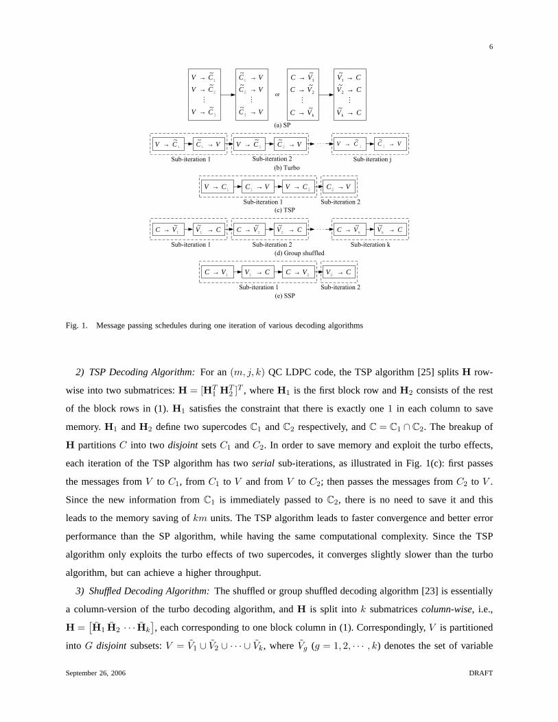
denotes the set of check nodes corresponding toHg. As shown in Fig. 1(a), each iteration of the SP
algorithm consists of two serial steps: first passes the messages fromV to all Cg ’s (g = 1, 2, · · · , j)
concurrentlyand then passes the messages from allCg ’s (g = 1, 2, · · · , j) to V concurrently. In the
turbo decoding, each iteration becomesj serial sub-iterations as shown in Fig. 1(b): first passes the
messages fromV to C1 and from C1 to V , then passes the messages fromV to C2 and from C2 to
V , and so on. Since within one iteration, one supercode can use the updated and hence more reliable
information fromprecedingsupercodes, the turbo algorithm requires fewer (up to50%) iterations and
achieves better error performance than the SP algorithm. Since the decoding of one supercode only needs
information from the other supercodes and the new information can overwrite the old information from
thesucceedingsupercode, this eliminates the need to save the extrinsic information of one supercode and
leads to memory saving ofkm units, but the number of additions per variable node for VNUs increases
roughly from2j to j2.
September 26, 2006 DRAFT
Page 6
6
������
�������
�������
� ������������
�������
������������� ������������� �������������
������������� �������������
������������� ������������� �������������
������������� �������������
1CV~→ VC →1
~2CV
~→ VC →2
~
1CV → VC →1 2CV → VC →2
1VC → CV →1 2VC → CV →2
1VC~→ CV →1
~2VC
~→ CV →2
~
�
j
2
1
CV
CV
CV
~
~
~
→
→
→
�
VC
VC
VC
→
→
→
j
2
1
~
~
~
�
kVC
VC
VC
~
~
~
2
1
→
→
→
�
CV
CV
CV
k →
→
→
~
~
~
2
1
�
jCV~→ VC →j
~
kVC~→ CV →k
~
Fig. 1. Message passing schedules during one iteration of various decoding algorithms
2) TSP Decoding Algorithm:For an(m, j, k) QC LDPC code, the TSP algorithm [25] splitsH row-
wise into two submatrices:H = [HT1 HT
2 ]T , whereH1 is the first block row andH2 consists of the rest
of the block rows in (1).H1 satisfies the constraint that there is exactly one1 in each column to save
memory.H1 andH2 define two supercodesC1 andC2 respectively, andC = C1 ∩ C2. The breakup of
H partitionsC into two disjoint setsC1 andC2. In order to save memory and exploit the turbo effects,
each iteration of the TSP algorithm has twoserial sub-iterations, as illustrated in Fig. 1(c): first passes
the messages fromV to C1, from C1 to V and fromV to C2; then passes the messages fromC2 to V .
Since the new information fromC1 is immediately passed toC2, there is no need to save it and this
leads to the memory saving ofkm units. The TSP algorithm leads to faster convergence and better error
performance than the SP algorithm, while having the same computational complexity. Since the TSP
algorithm only exploits the turbo effects of two supercodes, it converges slightly slower than the turbo
algorithm, but can achieve a higher throughput.
3) Shuffled Decoding Algorithm:The shuffled or group shuffled decoding algorithm [23] is essentially
a column-version of the turbo decoding algorithm, andH is split into k submatricescolumn-wise, i.e.,
H =[H1 H2 · · · Hk
], each corresponding to one block column in (1). Correspondingly,V is partitioned
into G disjoint subsets:V = V1 ∪ V2 ∪ · · · ∪ Vk, whereVg (g = 1, 2, · · · , k) denotes the set of variable
September 26, 2006 DRAFT
Page 7
7
nodes corresponding toHg. Alternatively, we may view each iteration of the SP algorithm as: first passes
the messages fromC to all Vg ’s (g = 1, 2, · · · , k) concurrentlyand then passes the messages from all
Vg ’s (g = 1, 2, · · · , k) to C concurrentlyas shown in Fig. 1(a). In the group shuffled decoding, each
iteration becomesk serial sub-iterations as shown in Fig. 1(d): first passes the messages fromC to V1
and from V1 to C, then passes the messages fromC to V2 and from V2 to C, and so on. The shuffled
decoding algorithm also achieves better error performances and faster convergence than the SP algorithm.
At the cost of increasing the number of additions andΨ(·) evaluations roughly from2k to k2 per check
node for check node updates (CNUs), the group shuffled decoding algorithm leads to memory saving of
jm units [23].
4) SSP Decoding Algorithm:The SSP algorithm [25] is essentially the column version of the TSP
algorithm andH is split column-wise into two submatrices:H = [H1 H2], whereH1 is the first block
column andH2 consists of the rest of block columns.H1 has exactly one1 in each row to save memory.
Correspondingly,V is split into twodisjoint setsV1 andV2, which correspond toH1 andH2 respectively.
As illustrated in Fig. 1(e), each iteration of our SSP algorithm also has twoserial sub-iterations: first
passes the messages fromC to V1, from V1 to C, and fromC to V2; then passes the messages fromV2
to C. Compared with the SP algorithm, the SSP algorithm has the same computational complexity, but
achieves better error performance, faster convergence, and memory saving ofjm units.
III. D ECODING ALGORITHMS FORPARTLY PARALLEL DECODERARCHITECTURES
In memory-banks based partly parallel decoders [7–9], due to memory access limitation, the CNUs
for the m rows in one block row and the VNUs for them columns in one block column are both
carried out sequentially. In this case, having more serial sub-iterations in each iteration as in the turbo or
shuffled algorithm leads to low decoding throughput. Hence, we focus on the TSP and SSP algorithms,
and propose the following two algorithms: PTST and PTSSP algorithms to further improve throughput
or memory saving of memory-banks based partly parallel decoder architectures.
A. PTSP Decoding of QC LDPC Codes
Similar to the non-overlapped SP decoding, the sequential processing of sub-iterations 1 and 2 in
the TSP algorithm leads to low throughput and low HUE assuming memory-banks based partly parallel
decoders. To improve the throughput and HUE, we propose a PTSP decoding algorithm, which essentially
parallelizes the processing in sub-iterations 1 and 2 of the TSP algorithm.
September 26, 2006 DRAFT
Page 8
8
���
���
1CV → VC →1 2CV →
VC →2
)(,2
nVCq)(
,2
nVCr
)1(,2
~ −nVCr
)(,1
~ nVCq )(
,1
~ nVCr
)1(,2
~ −nVCr
)(,2
~ nVCr
)(,2
~ nVCr
)(,2
~ nVCq
)(,2
~ nVCq
)1(,2
~ −nVCq )(
,2
~ nVCr
VC →2 1CV → VC →1 2CV →)(,1
nVCq )(
,1
nVCr)1(
,2
−nVCq
)(,2
nVCr
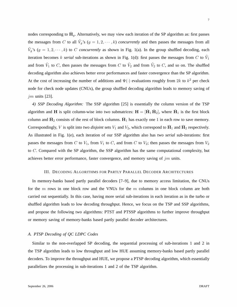
Fig. 2. Message passing during then-th iteration of (a) TSP (b) PTSP Decoding
We illustrate the difference between the TSP and PTSP algorithms during then-th iteration of decoding
in Figs. 2(a) and 2(b). For the TSP algorithm, we assume the memory banks are initialized with the
channel intrinsic LLRs and hence sub-iteration 2 starts first. To simplify notation, we denote the set
of messages from a setA of check nodes(A ⊆ C) to a setB of variable nodes(B ⊆ V ) during
the n-th iteration of the TSP decoding asr(n)A,B = {r(n)
l,i : l ∈ A, i ∈ B}, and that fromB to A as
q(n)A,B = {q(n)
l,i : l ∈ A, i ∈ B}. We denote those for the PTSP decoding asr(n)A,B and q
(n)A,B respectively. At
then-th iteration of the TSP decoding, the decoding ofC2 uses the extrinsic information of the(n−1)-th
iteration fromC1 and itself, i.e.,q(n−1)C2,V
is used when calculatingr(n)C2,V
, and the decoding ofC1 uses
the information of then-th iteration fromC2 , i.e., r(n)C2,V
is used when calculatingq(n)C2,V
. In the PTSP
decoding, since the decoding ofC1 andC2 is performed simultaneously, the most recent information
can be exchanged during the decoding process. At then-th iteration, at the beginning, the decoding of
C2 uses the extrinsic information of the(n− 1)-th iteration fromC1 and itself, i.e.,q(n−1)C2,V
is used when
calculatingr(n)C2,V
, and the decoding ofC1 also uses the information of the(n− 1)-th iteration fromC2
, i.e., r(n−1)C2,V
is used when calculatingq(n)C2,V
. As the decoding proceeds, when part of the information
of the n-th iteration fromC2 is available, the decoding ofC1 can use it, i.e.,r(n)C2,V
can be used when
calculatingq(n)C2,V
. The decoding ofC2 can then use the more reliable information fromC1, i.e., q(n)C2,V
can
be used when calculatingr(n)C2,V
. Even more reliable information fromC2 is then produced and passed
to C1. Thus, in the PTSP algorithm, more and more reliable information is exchanged between the two
supercodes as the decoding proceeds. However, each time only part of the information exchanged is from
September 26, 2006 DRAFT
Page 9
9
H �
11H12H
21H 22H
1C
2C
2V1V
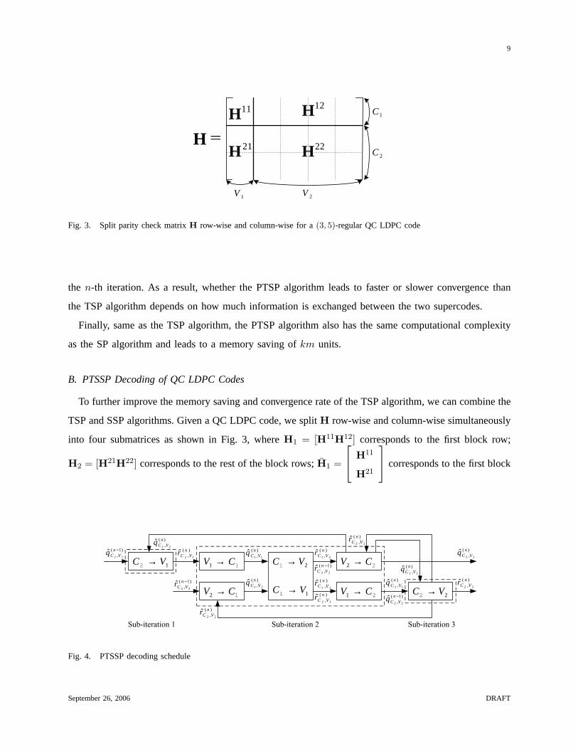
Fig. 3. Split parity check matrixH row-wise and column-wise for a(3, 5)-regular QC LDPC code
the n-th iteration. As a result, whether the PTSP algorithm leads to faster or slower convergence than
the TSP algorithm depends on how much information is exchanged between the two supercodes.
Finally, same as the TSP algorithm, the PTSP algorithm also has the same computational complexity
as the SP algorithm and leads to a memory saving ofkm units.
B. PTSSP Decoding of QC LDPC Codes
To further improve the memory saving and convergence rate of the TSP algorithm, we can combine the
TSP and SSP algorithms. Given a QC LDPC code, we splitH row-wise and column-wise simultaneously
into four submatrices as shown in Fig. 3, whereH1 = [H11H12] corresponds to the first block row;
H2 = [H21H22] corresponds to the rest of the block rows;H1 =
H11
H21
corresponds to the first block
1VC →2 1CV →1
1CV →2 1VC →1
2VC →1
2CV →1
2CV →2
2VC →2
������������ ������������� �������������
)1(, 22
ˆ −nVCq
)1(, 22
ˆ −nVCr
)(, 22
ˆ nVCq
)(, 12
ˆ nVCr )(
, 11ˆ n
VCq
)(, 21
ˆ nVCq
)(, 22
ˆ nVCr
)(, 21
ˆ nVCr
)1(, 22
ˆ −nVCr
)(, 11
ˆ nVCr)(, 12
ˆ nVCr
)(, 22
ˆ nVCq
)(, 22
ˆ nVCq
)(, 12
ˆ nVCq
)1(, 22
ˆ −nVCq
)(, 22
ˆ nVCr
)(, 22
ˆ nVCr
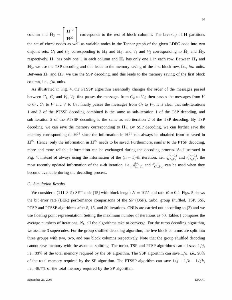
Fig. 4. PTSSP decoding schedule
September 26, 2006 DRAFT
Page 10
10
column andH2 =
H12
H22
corresponds to the rest of block columns. The breakup ofH partitions
the set of check nodes as well as variable nodes in the Tanner graph of the given LDPC code into two
disjoint sets:C1 and C2 corresponding toH1 and H2; and V1 and V2 corresponding toH1 and H2,
respectively.H1 has only one1 in each column andH1 has only one1 in each row. BetweenH1 and
H2, we use the TSP decoding and this leads to the memory saving of the first block row, i.e.,km units.
BetweenH1 and H2, we use the SSP decoding, and this leads to the memory saving of the first block
column, i.e.,jm units.
As illustrated in Fig. 4, the PTSSP algorithm essentially changes the order of the messages passed
betweenC1, C2 andV1, V2: first passes the messages fromC2 to V1; then passes the messages fromV
to C1, C1 to V and V to C2; finally passes the messages fromC2 to V2. It is clear that sub-iterations
1 and 3 of the PTSSP decoding combined is the same as sub-iteration 1 of the TSP decoding, and
sub-iteration 2 of the PTSSP decoding is the same as sub-iteration 2 of the TSP decoding. By TSP
decoding, we can save the memory corresponding toH1. By SSP decoding, we can further save the
memory corresponding toH21 since the information inH21 can always be obtained from or saved in
H22. Hence, only the information inH22 needs to be saved. Furthermore, similar to the PTSP decoding,
more and more reliable information can be exchanged during the decoding process. As illustrated in
Fig. 4, instead of always using the information of the(n − 1)-th iteration, i.e.,q(n−1)C2,V2
and r(n−1)C2,V2
, the
most recently updated information of then-th iteration, i.e.,q(n)C2,V2
and r(n)C2,V2
, can be used when they
become available during the decoding process.
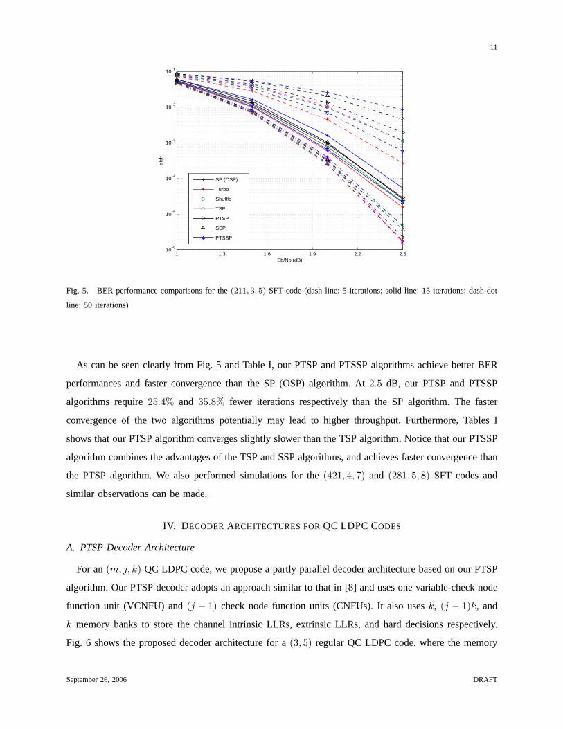
C. Simulation Results
We consider a(211, 3, 5) SFT code [15] with block lengthN = 1055 and rateR ≈ 0.4. Figs. 5 shows
the bit error rate (BER) performance comparisons of the SP (OSP), turbo, group shuffled, TSP, SSP,
PTSP and PTSSP algorithms after5, 15, and50 iterations. CNUs are carried out according to (2) and we
use floating point representation. Setting the maximum number of iterations as50, Tables I compares the
average numbers of iterations,Nt, all the algorithms take to converge. For the turbo decoding algorithm,
we assume3 supercodes. For the group shuffled decoding algorithm, the five block columns are split into
three groups with two, two, and one block columns respectively. Note that the group shuffled decoding
cannot save memory with the assumed splitting. The turbo, TSP and PTSP algorithms can all save1/j,
i.e., 33% of the total memory required by the SP algorithm. The SSP algorithm can save1/k, i.e., 20%
of the total memory required by the SP algorithm. The PTSSP algorithm can save1/j + 1/k − 1/jk,
i.e., 46.7% of the total memory required by the SP algorithm.
September 26, 2006 DRAFT
Page 11
11
1 1.3 1.6 1.9 2.2 2.510
−6
10−5
10−4
10−3
10−2
10−1
Eb/No (dB)
BE
R
SP (OSP)
Turbo
Shuffle
TSP
PTSP
SSP
PTSSP
Fig. 5. BER performance comparisons for the(211, 3, 5) SFT code (dash line: 5 iterations; solid line: 15 iterations; dash-dot
line: 50 iterations)
As can be seen clearly from Fig. 5 and Table I, our PTSP and PTSSP algorithms achieve better BER
performances and faster convergence than the SP (OSP) algorithm. At2.5 dB, our PTSP and PTSSP
algorithms require25.4% and 35.8% fewer iterations respectively than the SP algorithm. The faster
convergence of the two algorithms potentially may lead to higher throughput. Furthermore, Tables I
shows that our PTSP algorithm converges slightly slower than the TSP algorithm. Notice that our PTSSP
algorithm combines the advantages of the TSP and SSP algorithms, and achieves faster convergence than
the PTSP algorithm. We also performed simulations for the(421, 4, 7) and (281, 5, 8) SFT codes and
similar observations can be made.
IV. D ECODERARCHITECTURES FORQC LDPC CODES
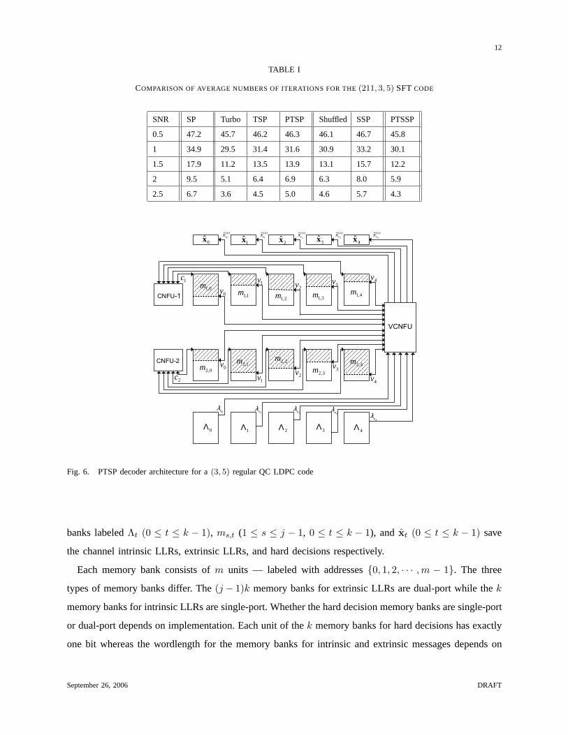
A. PTSP Decoder Architecture
For an(m, j, k) QC LDPC code, we propose a partly parallel decoder architecture based on our PTSP
algorithm. Our PTSP decoder adopts an approach similar to that in [8] and uses one variable-check node
function unit (VCNFU) and(j − 1) check node function units (CNFUs). It also usesk, (j − 1)k, and
k memory banks to store the channel intrinsic LLRs, extrinsic LLRs, and hard decisions respectively.
Fig. 6 shows the proposed decoder architecture for a(3, 5) regular QC LDPC code, where the memory
September 26, 2006 DRAFT
Page 12
12
TABLE I
COMPARISON OF AVERAGE NUMBERS OF ITERATIONS FOR THE(211, 3, 5) SFT CODE
SNR SP Turbo TSP PTSP Shuffled SSP PTSSP
0.5 47.2 45.7 46.2 46.3 46.1 46.7 45.8
1 34.9 29.5 31.4 31.6 30.9 33.2 30.1
1.5 17.9 11.2 13.5 13.9 13.1 15.7 12.2
2 9.5 5.1 6.4 6.9 6.3 8.0 5.9
2.5 6.7 3.6 4.5 5.0 4.6 5.7 4.3
������
�����
������
0vλ1vλ
2vλ3vλ
4vλ
4x3x2x1x0x)(
0ˆ n
vx )(
1ˆ n
vx )(
2ˆ n
vx )(
3ˆ n
vx )(
4ˆ n
vx
3,1m 4,1m
0,2m 1,2m 2,2m
3,2m4,2m
0,1m1,1m
2,1m
1c
2c
0v
0v
1v
1v
2v
2v
3v
3v
4v
4v
0Λ 1Λ 2Λ 3Λ 4Λ
Fig. 6. PTSP decoder architecture for a(3, 5) regular QC LDPC code
banks labeledΛt (0 ≤ t ≤ k − 1), ms,t (1 ≤ s ≤ j − 1, 0 ≤ t ≤ k − 1), and xt (0 ≤ t ≤ k − 1) save
the channel intrinsic LLRs, extrinsic LLRs, and hard decisions respectively.
Each memory bank consists ofm units — labeled with addresses{0, 1, 2, · · · ,m − 1}. The three
types of memory banks differ. The(j − 1)k memory banks for extrinsic LLRs are dual-port while thek
memory banks for intrinsic LLRs are single-port. Whether the hard decision memory banks are single-port
or dual-port depends on implementation. Each unit of thek memory banks for hard decisions has exactly
one bit whereas the wordlength for the memory banks for intrinsic and extrinsic messages depends on
September 26, 2006 DRAFT
Page 13
13
�
�
�
� �
������
�
� �
�
� �
�
0vλ
1vλ
4vλ
)(
0ˆ n
vx
)(
1ˆ n
vx
)(
4ˆ n
vx
)( 00,1 vm
)( 00,2 vm
)( 11,2 vm
)( 11,1 vm
)( 44,1 vm
)( 44,2 vm
)( 00,1 vm
)( 00,2 vm
)( 11,1 vm
)( 11,2 vm
)( 44,1 vm
)( 44,2 vm
)( 00,0 cm
)( 01,0 cm
)( 04,0 cm
)( 00,0 cm
)( 01,0 cm
)( 04,0 cm
������
�����
�����
������ �������
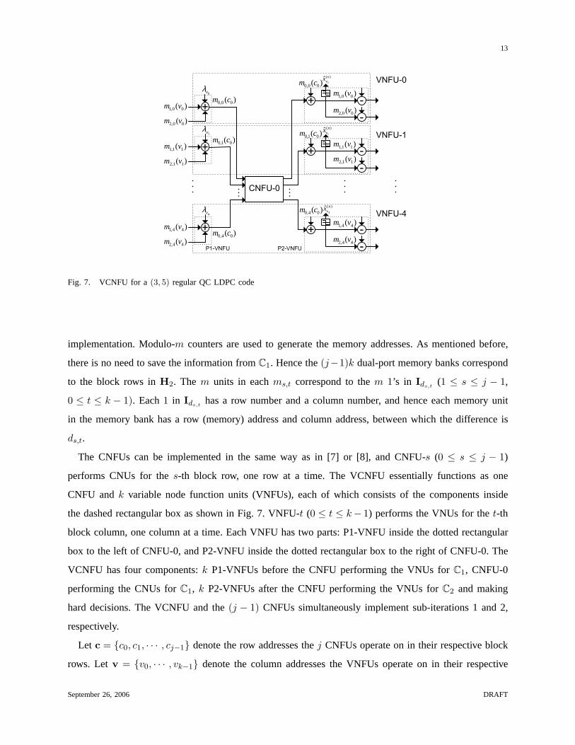
Fig. 7. VCNFU for a(3, 5) regular QC LDPC code
implementation. Modulo-m counters are used to generate the memory addresses. As mentioned before,
there is no need to save the information fromC1. Hence the(j−1)k dual-port memory banks correspond
to the block rows inH2. The m units in eachms,t correspond to them 1’s in Ids,t(1 ≤ s ≤ j − 1,
0 ≤ t ≤ k − 1). Each1 in Ids,thas a row number and a column number, and hence each memory unit
in the memory bank has a row (memory) address and column address, between which the difference is
ds,t.
The CNFUs can be implemented in the same way as in [7] or [8], and CNFU-s (0 ≤ s ≤ j − 1)
performs CNUs for thes-th block row, one row at a time. The VCNFU essentially functions as one
CNFU andk variable node function units (VNFUs), each of which consists of the components inside
the dashed rectangular box as shown in Fig. 7. VNFU-t (0 ≤ t ≤ k− 1) performs the VNUs for thet-th
block column, one column at a time. Each VNFU has two parts: P1-VNFU inside the dotted rectangular
box to the left of CNFU-0, and P2-VNFU inside the dotted rectangular box to the right of CNFU-0. The
VCNFU has four components:k P1-VNFUs before the CNFU performing the VNUs forC1, CNFU-0
performing the CNUs forC1, k P2-VNFUs after the CNFU performing the VNUs forC2 and making
hard decisions. The VCNFU and the(j − 1) CNFUs simultaneously implement sub-iterations 1 and 2,
respectively.
Let c = {c0, c1, · · · , cj−1} denote the row addresses thej CNFUs operate on in their respective block
rows. Letv = {v0, · · · , vk−1} denote the column addresses the VNFUs operate on in their respective
September 26, 2006 DRAFT
Page 14
14
0c
1c
2c
0v 1v 2v3v 4v
0,1m 1,1m 2,1m 3,1m 4,1m
0,2m 1,2m 2,2m 3,2m 4,2m
0,0m 1,0m 2,0m 3,0m 4,0m
V
1C
2C
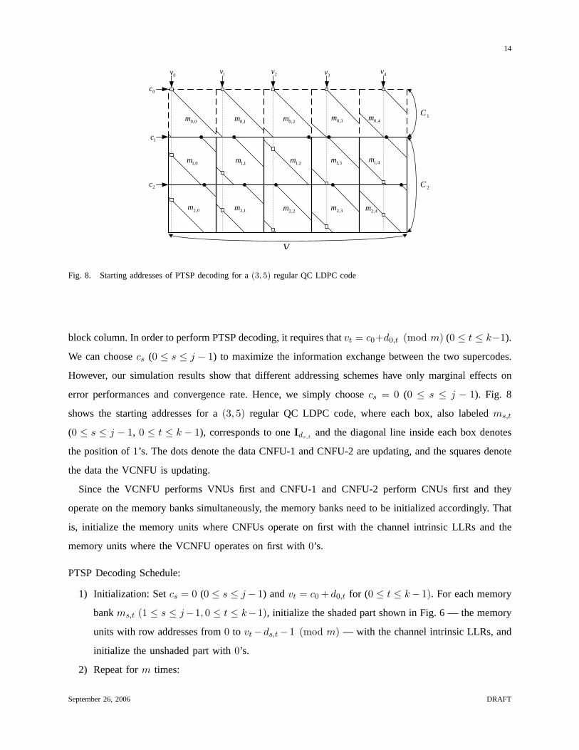
Fig. 8. Starting addresses of PTSP decoding for a(3, 5) regular QC LDPC code
block column. In order to perform PTSP decoding, it requires thatvt = c0+d0,t (mod m) (0 ≤ t ≤ k−1).
We can choosecs (0 ≤ s ≤ j − 1) to maximize the information exchange between the two supercodes.
However, our simulation results show that different addressing schemes have only marginal effects on
error performances and convergence rate. Hence, we simply choosecs = 0 (0 ≤ s ≤ j − 1). Fig. 8
shows the starting addresses for a(3, 5) regular QC LDPC code, where each box, also labeledms,t
(0 ≤ s ≤ j − 1, 0 ≤ t ≤ k − 1), corresponds to oneIds,tand the diagonal line inside each box denotes
the position of1’s. The dots denote the data CNFU-1 and CNFU-2 are updating, and the squares denote
the data the VCNFU is updating.
Since the VCNFU performs VNUs first and CNFU-1 and CNFU-2 perform CNUs first and they
operate on the memory banks simultaneously, the memory banks need to be initialized accordingly. That
is, initialize the memory units where CNFUs operate on first with the channel intrinsic LLRs and the
memory units where the VCNFU operates on first with0’s.
PTSP Decoding Schedule:
1) Initialization: Setcs = 0 (0 ≤ s ≤ j− 1) andvt = c0 + d0,t for (0 ≤ t ≤ k− 1). For each memory
bankms,t (1 ≤ s ≤ j−1, 0 ≤ t ≤ k−1), initialize the shaded part shown in Fig. 6 — the memory
units with row addresses from0 to vt−ds,t− 1 (mod m) — with the channel intrinsic LLRs, and
initialize the unshaded part with0’s.
2) Repeat form times:
September 26, 2006 DRAFT
Page 15
15
������
0vλ1vλ
2vλ3vλ
4vλ
4x3x2x1x0x
0Λ 1Λ 2Λ 3Λ4Λ
1,1m2,1m 3,1m
4,1m
1,2m 2,2m3,2m 4,2m
1c
2c
1v
1v
2v
3v
3v 4v
4v
1c1c
1c
2v
2c 2c2c
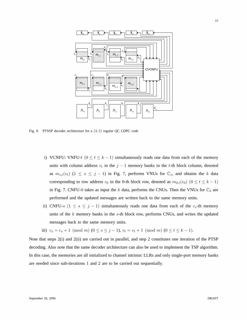
Fig. 9. PTSSP decoder architecture for a(3, 5) regular QC LDPC code
i) VCNFU: VNFU-t (0 ≤ t ≤ k − 1) simultaneously reads one data from each of the memory
units with column addressvt in the j − 1 memory banks in thet-th block column, denoted
as ms,t(vt) (1 ≤ s ≤ j − 1) in Fig. 7, performs VNUs forC1, and obtains thek data
corresponding to row addressc0 in the 0-th block row, denoted asm0,t(c0) (0 ≤ t ≤ k − 1)
in Fig. 7. CNFU-0 takes as input thek data, performs the CNUs. Then the VNUs forC2 are
performed and the updated messages are written back to the same memory units.
ii) CNFU-s (1 ≤ s ≤ j − 1) simultaneously reads one data from each of thecs-th memory
units of thek memory banks in thes-th block row, performs CNUs, and writes the updated
messages back to the same memory units.
iii) cs = cs + 1 (mod m) (0 ≤ s ≤ j − 1), vt = vt + 1 (mod m) (0 ≤ t ≤ k − 1).
Note that steps 2(i) and 2(ii) are carried out in parallel, and step 2 constitutes one iteration of the PTSP
decoding. Also note that the same decoder architecture can also be used to implement the TSP algorithm.
In this case, the memories are all initialized to channel intrinsic LLRs and only single-port memory banks
are needed since sub-iterations 1 and 2 are to be carried out sequentially.
September 26, 2006 DRAFT
Page 16
16
�
�
�
������
�
�
�
�
)( 11,1 cm
)( 12,1 cm
)( 14,1 cm
( )∏=
4
11,1 )(sgn
tt cm
( )∏=
4
12,2 )(sgn
tt cm )( 00,1 vm
)( 00,2 vm
)( 11,1 vm
)( 11,2 vm
)( 44,1 vm
)( 44,2 vm
)( 21,2 cm
)( 22,2 cm
)( 24,2 cm
( )�=
Ψ4
11,1 )(
tt cm
( ))( 14,1 cmΨ
��
�
( ))( 11,1 cmΨ
( ))( 12,1 cmΨ
�
�
�
�
��
�
( ))( 21,2 cmΨ
( ))( 22,2 cmΨ
( ))( 24,2 cmΨ
( )�=
Ψ4
12,2 )(
tt cm
( )∏≠=
4
1,01,1 )(sgn
ttt cm
( )∏≠=
4
2,01,1 )(sgn
ttt cm
( )∏≠=
4
4,01,1 )(sgn
ttt cm
( )∏≠=
4
1,02,2 )(sgn
ttt cm
( )∏≠=
4
2,02,2 )(sgn
ttt cm
( )∏≠=
4
4,02,2 )(sgn
ttt cm
������
�����
( )•Ψ
( )•Ψ
( )•Ψ
( )•Ψ
( )•Ψ
( )•Ψ
( )•Ψ
( )•Ψ
)(•Ψ
)(•Ψ
)(•Ψ
)(•Ψ
)(•Ψ
)(•Ψ
)(•Ψ
)(•Ψ
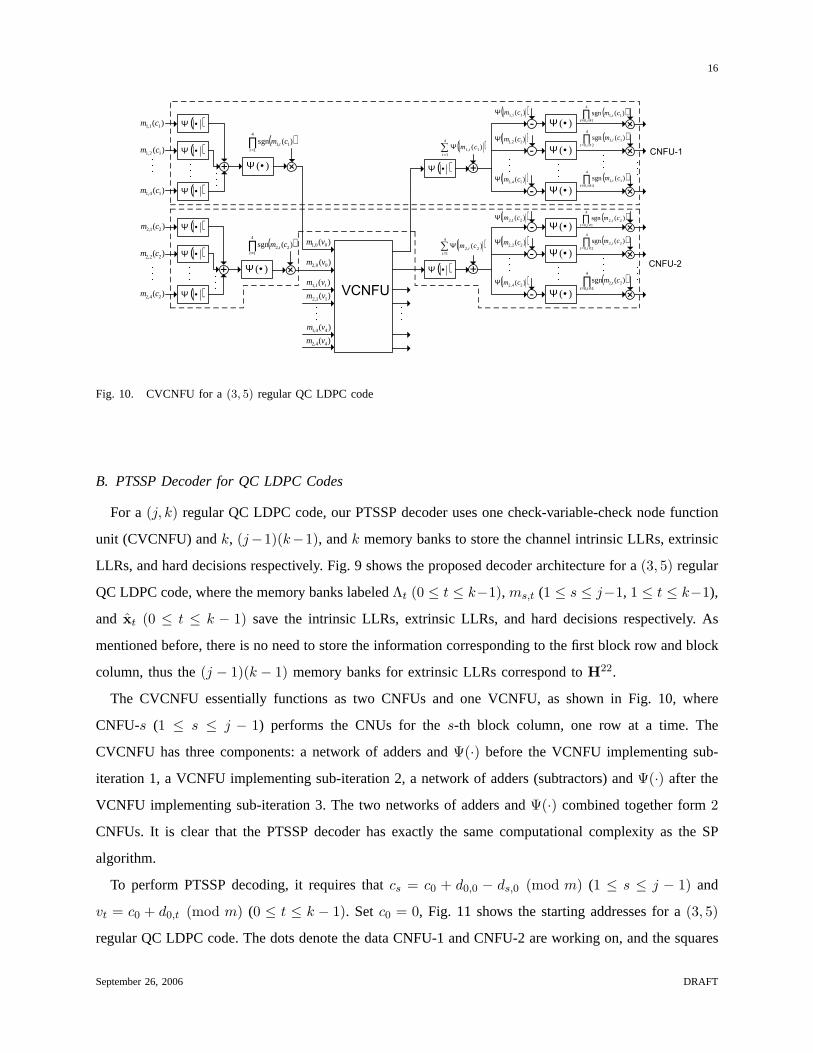
Fig. 10. CVCNFU for a(3, 5) regular QC LDPC code
B. PTSSP Decoder for QC LDPC Codes
For a(j, k) regular QC LDPC code, our PTSSP decoder uses one check-variable-check node function
unit (CVCNFU) andk, (j−1)(k−1), andk memory banks to store the channel intrinsic LLRs, extrinsic
LLRs, and hard decisions respectively. Fig. 9 shows the proposed decoder architecture for a(3, 5) regular
QC LDPC code, where the memory banks labeledΛt (0 ≤ t ≤ k−1), ms,t (1 ≤ s ≤ j−1, 1 ≤ t ≤ k−1),
and xt (0 ≤ t ≤ k − 1) save the intrinsic LLRs, extrinsic LLRs, and hard decisions respectively. As
mentioned before, there is no need to store the information corresponding to the first block row and block
column, thus the(j − 1)(k − 1) memory banks for extrinsic LLRs correspond toH22.
The CVCNFU essentially functions as two CNFUs and one VCNFU, as shown in Fig. 10, where
CNFU-s (1 ≤ s ≤ j − 1) performs the CNUs for thes-th block column, one row at a time. The
CVCNFU has three components: a network of adders andΨ(·) before the VCNFU implementing sub-
iteration 1, a VCNFU implementing sub-iteration 2, a network of adders (subtractors) andΨ(·) after the
VCNFU implementing sub-iteration 3. The two networks of adders andΨ(·) combined together form2
CNFUs. It is clear that the PTSSP decoder has exactly the same computational complexity as the SP
algorithm.
To perform PTSSP decoding, it requires thatcs = c0 + d0,0 − ds,0 (mod m) (1 ≤ s ≤ j − 1) and
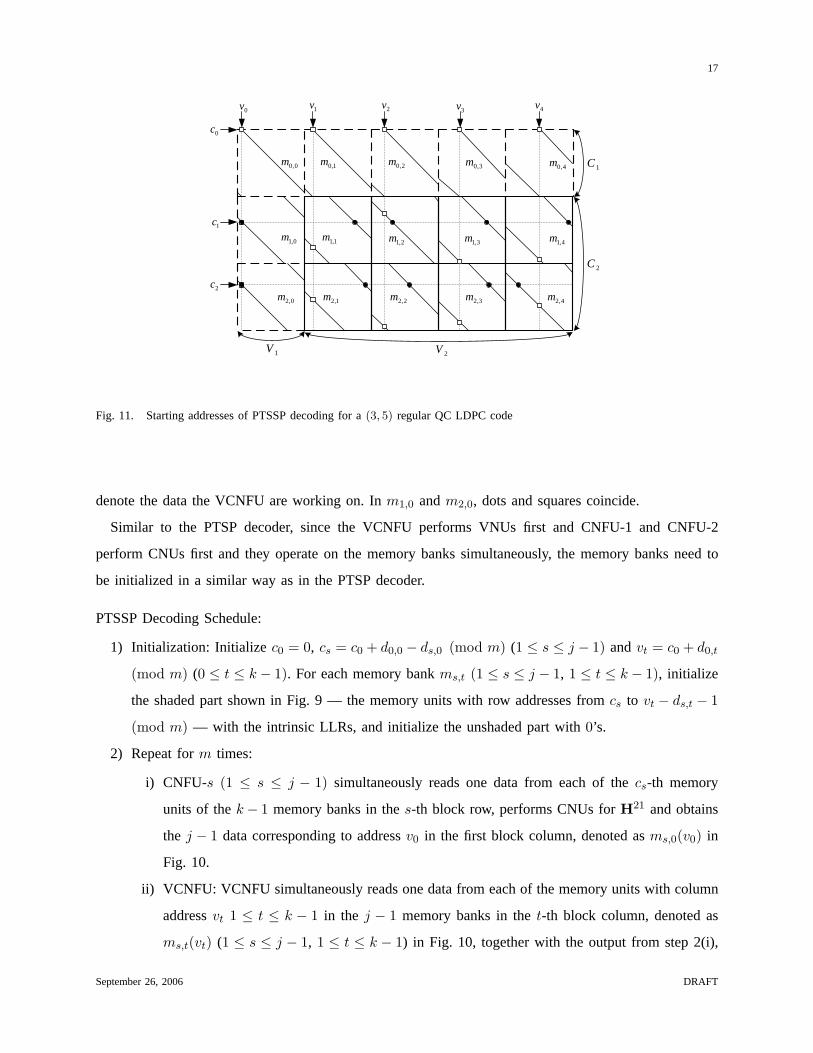
vt = c0 + d0,t (mod m) (0 ≤ t ≤ k − 1). Setc0 = 0, Fig. 11 shows the starting addresses for a(3, 5)
regular QC LDPC code. The dots denote the data CNFU-1 and CNFU-2 are working on, and the squares
September 26, 2006 DRAFT
Page 17
17
0c
1c
2c
0v 1v 2v3v 4v
0,0m 1,0m
0,1m
0,2m
1,1m
1,2m
2,0m
2,1m
2,2m
3,0m 4,0m
3,1m
3,2m
4,1m
4,2m
1C
2C
1V 2V
Fig. 11. Starting addresses of PTSSP decoding for a(3, 5) regular QC LDPC code
denote the data the VCNFU are working on. Inm1,0 andm2,0, dots and squares coincide.
Similar to the PTSP decoder, since the VCNFU performs VNUs first and CNFU-1 and CNFU-2
perform CNUs first and they operate on the memory banks simultaneously, the memory banks need to
be initialized in a similar way as in the PTSP decoder.
PTSSP Decoding Schedule:
1) Initialization: Initialize c0 = 0, cs = c0 + d0,0 − ds,0 (mod m) (1 ≤ s ≤ j − 1) andvt = c0 + d0,t
(mod m) (0 ≤ t ≤ k − 1). For each memory bankms,t (1 ≤ s ≤ j − 1, 1 ≤ t ≤ k − 1), initialize
the shaded part shown in Fig. 9 — the memory units with row addresses fromcs to vt − ds,t − 1
(mod m) — with the intrinsic LLRs, and initialize the unshaded part with0’s.
2) Repeat form times:
i) CNFU-s (1 ≤ s ≤ j − 1) simultaneously reads one data from each of thecs-th memory
units of thek− 1 memory banks in thes-th block row, performs CNUs forH21 and obtains
the j − 1 data corresponding to addressv0 in the first block column, denoted asms,0(v0) in
Fig. 10.
ii) VCNFU: VCNFU simultaneously reads one data from each of the memory units with column
addressvt 1 ≤ t ≤ k − 1 in the j − 1 memory banks in thet-th block column, denoted as
ms,t(vt) (1 ≤ s ≤ j − 1, 1 ≤ t ≤ k − 1) in Fig. 10, together with the output from step 2(i),
September 26, 2006 DRAFT
Page 18
18
1 1.5 2 2.5 3 3.5 4
10−7
10−6
10−5
10−4
10−3
10−2
10−1
Eb/No (dB)
BE
RMS−floating
MS−fixed
PTSP−MS−floating
PTSP−MS−fixed
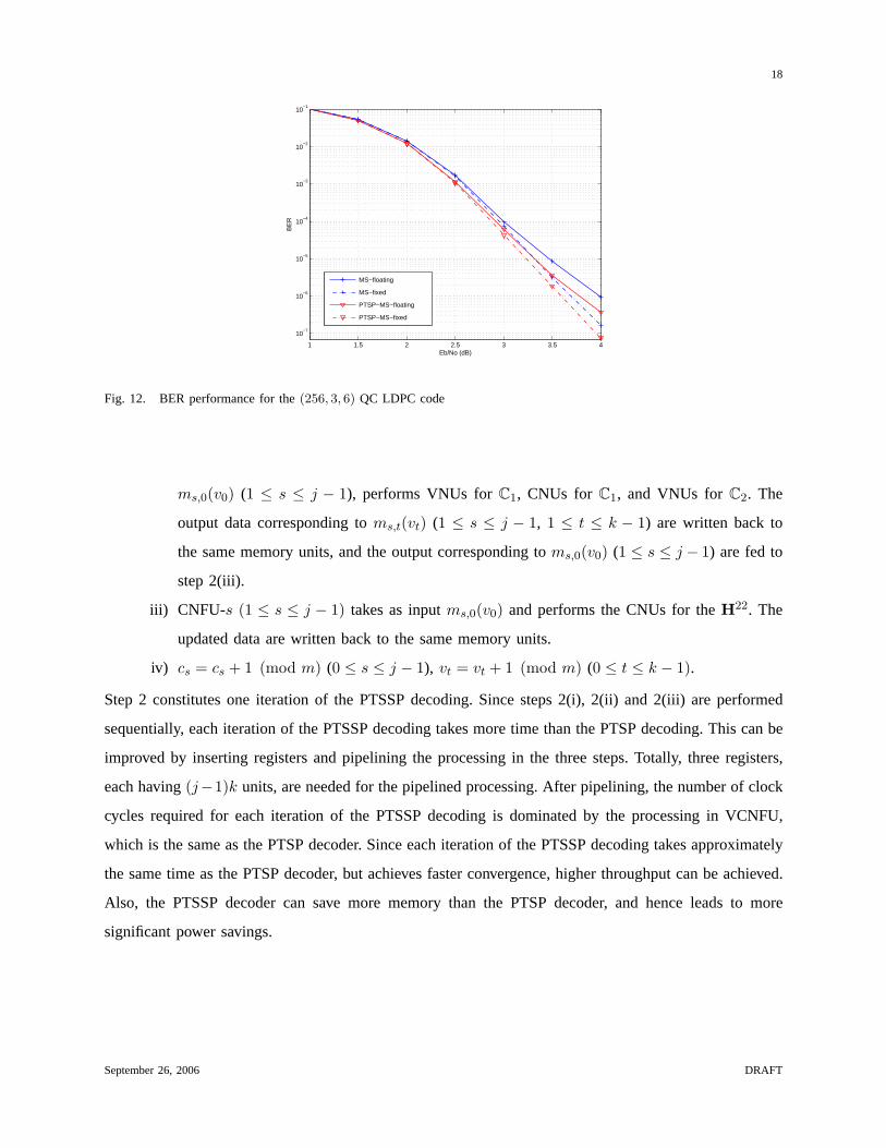
Fig. 12. BER performance for the(256, 3, 6) QC LDPC code
ms,0(v0) (1 ≤ s ≤ j − 1), performs VNUs forC1, CNUs forC1, and VNUs forC2. The
output data corresponding toms,t(vt) (1 ≤ s ≤ j − 1, 1 ≤ t ≤ k − 1) are written back to
the same memory units, and the output corresponding toms,0(v0) (1 ≤ s ≤ j − 1) are fed to
step 2(iii).
iii) CNFU-s (1 ≤ s ≤ j − 1) takes as inputms,0(v0) and performs the CNUs for theH22. The
updated data are written back to the same memory units.
iv) cs = cs + 1 (mod m) (0 ≤ s ≤ j − 1), vt = vt + 1 (mod m) (0 ≤ t ≤ k − 1).
Step 2 constitutes one iteration of the PTSSP decoding. Since steps 2(i), 2(ii) and 2(iii) are performed
sequentially, each iteration of the PTSSP decoding takes more time than the PTSP decoding. This can be
improved by inserting registers and pipelining the processing in the three steps. Totally, three registers,
each having(j−1)k units, are needed for the pipelined processing. After pipelining, the number of clock
cycles required for each iteration of the PTSSP decoding is dominated by the processing in VCNFU,
which is the same as the PTSP decoder. Since each iteration of the PTSSP decoding takes approximately
the same time as the PTSP decoder, but achieves faster convergence, higher throughput can be achieved.
Also, the PTSSP decoder can save more memory than the PTSP decoder, and hence leads to more
significant power savings.
September 26, 2006 DRAFT
Page 19
19
1 1.5 2 2.5 3 3.5 4 4.52
4
6
8
10
12
14
16
18
20
Eb/No (dB)
Ave
rage
No.
of i
tera
tions
to c
onve
rge
MS−floatingMS−fixedPTSP−MS−floatingPTSP−MS−fixed
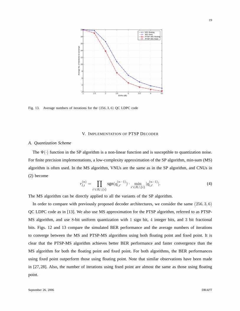
Fig. 13. Average numbers of iterations for the(256, 3, 6) QC LDPC code
V. I MPLEMENTATION OF PTSP DECODER
A. Quantization Scheme
TheΨ(·) function in the SP algorithm is a non-linear function and is susceptible to quantization noise.
For finite precision implementations, a low-complexity approximation of the SP algorithm, min-sum (MS)
algorithm is often used. In the MS algorithm, VNUs are the same as in the SP algorithm, and CNUs in
(2) become
r(n)l,i =
∏
i′∈Rl\{i}sgn(q(n−1)
l,i′ ) · mini′∈Rl\{i}
|q(n−1)l,i′ |. (4)
The MS algorithm can be directly applied to all the variants of the SP algorithm.
In order to compare with previously proposed decoder architectures, we consider the same(256, 3, 6)
QC LDPC code as in [13]. We also use MS approximation for the PTSP algorithm, referred to as PTSP-
MS algorithm, and use8-bit uniform quantization with1 sign bit, 4 integer bits, and3 bit fractional
bits. Figs. 12 and 13 compare the simulated BER performance and the average numbers of iterations
to converge between the MS and PTSP-MS algorithms using both floating point and fixed point. It is
clear that the PTSP-MS algorithm achieves better BER performance and faster convergence than the
MS algorithm for both the floating point and fixed point. For both algorithms, the BER performances
using fixed point outperform those using floating point. Note that similar observations have been made
in [27,28]. Also, the number of iterations using fixed point are almost the same as those using floating
point.
September 26, 2006 DRAFT
Page 20
20
������� ������ �� ����� ����������
�� ����� ��������� ���������� ��������������
�������������
������ ��������������
������ ��� �� ���
������ ����� ����������������������� ��������������
�� �����
����������������������� ����������
������ ����� �� �����
���
���
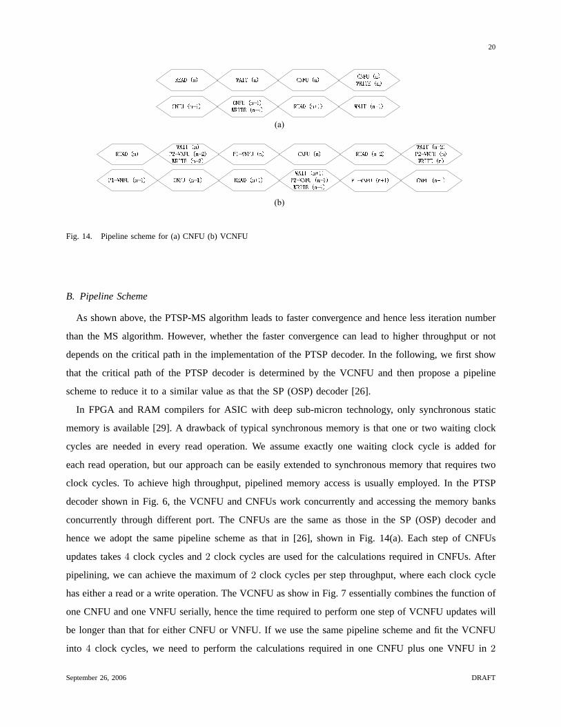
Fig. 14. Pipeline scheme for (a) CNFU (b) VCNFU
B. Pipeline Scheme
As shown above, the PTSP-MS algorithm leads to faster convergence and hence less iteration number
than the MS algorithm. However, whether the faster convergence can lead to higher throughput or not
depends on the critical path in the implementation of the PTSP decoder. In the following, we first show
that the critical path of the PTSP decoder is determined by the VCNFU and then propose a pipeline
scheme to reduce it to a similar value as that the SP (OSP) decoder [26].
In FPGA and RAM compilers for ASIC with deep sub-micron technology, only synchronous static
memory is available [29]. A drawback of typical synchronous memory is that one or two waiting clock
cycles are needed in every read operation. We assume exactly one waiting clock cycle is added for
each read operation, but our approach can be easily extended to synchronous memory that requires two
clock cycles. To achieve high throughput, pipelined memory access is usually employed. In the PTSP
decoder shown in Fig. 6, the VCNFU and CNFUs work concurrently and accessing the memory banks
concurrently through different port. The CNFUs are the same as those in the SP (OSP) decoder and
hence we adopt the same pipeline scheme as that in [26], shown in Fig. 14(a). Each step of CNFUs
updates takes4 clock cycles and2 clock cycles are used for the calculations required in CNFUs. After
pipelining, we can achieve the maximum of2 clock cycles per step throughput, where each clock cycle
has either a read or a write operation. The VCNFU as show in Fig. 7 essentially combines the function of
one CNFU and one VNFU serially, hence the time required to perform one step of VCNFU updates will
be longer than that for either CNFU or VNFU. If we use the same pipeline scheme and fit the VCNFU
into 4 clock cycles, we need to perform the calculations required in one CNFU plus one VNFU in2
September 26, 2006 DRAFT
Page 21
21
clock cycles. Compared to the case for CNFUs, more calculations are required in each clock cycle. The
critical path of the PTSP decoder is thus determined by the longer path in the VCNFU update. To reduce
the critical path while maintaining the2 clock cycles per step throughput, we use a different pipeline
scheme for VCNFU as shown in Fig. 14(b).
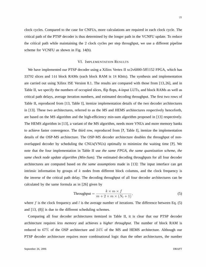
VI. I MPLEMENTATION RESULTS
We have implemented our PTSP decoder using a Xilinx Vertex II xc2v6000-5ff1152 FPGA, which has
33792 slices and144 block RAMs (each block RAM is18 Kbits). The synthesis and implementation
are carried out using Xilinx ISE Version 8.1. The results are compared with those from [13,26], and in
Table II, we specify the numbers of occupied slices, flip flops, 4-input LUTs, and block RAMs as well as
critical path delays, average iteration numbers, and estimated decoding throughput. The first two rows of
Table II, reproduced from [13, Table I], itemize implementation details of the two decoder architectures
in [13]. These two architectures, referred to as theMS andHEMSarchitectures respectively henceforth,
are based on the MS algorithm and the high-efficiency min-sum algorithm proposed in [13] respectively.
The HEMS algorithm in [13], a variant of the MS algorithm, needs more VNUs and more memory banks
to achieve faster convergence. The third row, reproduced from [?, Table I], itemize the implementation
details of the OSP-MS architecture. The OSP-MS decoder architecture doubles the throughput of non-
overlapped decoder by scheduling the CNUs(VNUs) optimally to minimize the waiting time [?]. We
note that the four implementation in Table II usethe same FPGA, the same quantization scheme, the
same check node update algorithm (Min-Sum). The estimated decoding throughputs for all four decoder
architectures are computed based onthe same assumptionsmade in [13]: The input interface can get
intrinsic information by groups ofk nodes from different block columns, and the clock frequency is
the inverse of the critical path delay. The decoding throughput of all four decoder architectures can be
calculated by the same formula as in [26] given by
Throughput=k ×m× f
m + 2×m× (Nt + 1), (5)
wheref is the clock frequency andl is the average number of iterations. The difference between Eq. (5)
and [13, (8)] is due to the different scheduling schemes.
Comparing all four decoder architectures itemized in Table II, it is clear that our PTSP decoder
architecture requiresless memoryand achieves ahigher throughput. The number of block RAM is
reduced to67% of the OSP architecture and24% of the MS and HEMS architecture. Although our
PTSP decoder architecture requires more combinational logic than the other architectures, the number
September 26, 2006 DRAFT
Page 22
22
TABLE II
IMPLEMENTATION RESULTS OF THE(256, 3, 6) QC LDPCCODE ONX ILINX V IRTEXII XC2V6000-5FF1152 FPGA
Architecture Slice F/F 4-input
LUT
Block
RAM
Critical Path
Delay [ns]
Nt Throughput
(Mbps)
MS [13] 1144 1089 1705 102 9.894 3.4 23
High-efficiency MS [13] 1296 1358 1785 102 9.900 2.0 38
OSP-MS [26] 1167 664 2066 36 10.893 3.0 61.2
PTSP-MS 1463 819 2534 24 11.933 2.3 66.1
of flip-flops is less than those of the MS and HEMS architectures. Memory efficiency of our decoder
architecture will enable implementation on small FPGAs and simplify the placement and routing in ASIC
implementation. As shown in Table II, the critical path delay of our PTSP architecture is greater than
those of the other architectures, but it still provides the highest throughput. Nearly triple the throughput
of the MS architecture, the throughput of our PTSP decoder architecture is74% higher than that of the
HEMS architecture despite fewer iterations required by the latter.
In comparison to the OSP decoder architecture proposed in [8,9], it is clear that our PTSP decoder has
exactly the same computational complexity, but requires less memory, thus less memory access and less
power consumption. Also, our PTSP decoder requires simpler control than the OSP decoder since in the
OSP decoder [9], in order to satisfy the data dependency constraints, the starting addresses need to be
shifted at each iteration, and the hardware needs to be turned on and off regularly whenw∗ ≥ bm/2c+1
[9]. Finally, due to the faster convergence of the PTSP algorithm as shown in Section III-C, our PTSP
decoder may lead to higher throughput than the OSP decoder.
VII. C ONCLUSIONS
REFERENCES
[1] R. G. Gallager, “Low Density Parity Check Codes,”MIT Press, 1963.
[2] Y. Kou, S. Lin and M. P. C. Fossorier, “Low-Density Parity-Check Codes Based on Finite Geometries: A Rediscovery and
New Results,”IEEE Trans. Info. Theory, vol. 47, pp. 2711–2736, Nov. 2001.
[3] A. Blanksby and C. Howland, “A 690-mw 1-Gbps 1024-b rate-1/2 Low-Density Parity-Check Code Decoder,”IEEE
Journal of Solid State Circuits, vol. 37, pp. 404–412, March 2002.
[4] A. Darabiha, A. C. Carusone and F. R. Kschischang, “Multi-Gbit/sec Low Density Parity Check Decoders with Reduced
Interconnect Complexity,”in Proc. IEEE Int. Symp. on Circuits and Systems (ISCAS), vol. 5, pp. 5194–5197, May 2005.
[5] E. Liao, E. Yeo and B. Nikolic, “Low-density Parity-check Code Constructions for Hardware Implementation,”in Proc.
IEEE Int. Conf. on Commun. (ICC), vol. 5, pp. 2573–2577, June 2004.
September 26, 2006 DRAFT
Page 23
23
[6] S. Olcer, “Decoder Architecture for Array-Code-Based LDPC Codes,”in Proc. Global Telecomun. Conf. (Globecom),
vol. 4, pp. 2046–2050, Dec. 2003.
[7] M. M. Mansour and N. R. Shanbhag, “Low Power VLSI Decoder Architecture for LDPC Codes,”in Proc. IEEE Int. Symp.
on Low Power Electronics and Design (ISLPED), pp. 284–289, Aug. 2002.
[8] Y. Chen and K. K. Parhi, “Overlapped Message Passing for Quasi-Cyclic Low Density Parity Check Codes,”IEEE Trans.
Circuits and Systems, vol. 51, pp. 1106–1113, June 2004.
[9] Y. Dai and Z. Yan, “Optimal Overlapped Message Passing Decoding for Quasi-Cyclic Low-Density Parity-Check Codes,”
in Proc. Global Telecomun. Conf. (Globecom), vol. 4, pp. 2395–2399, Dec. 2005.
[10] E. Yeo, P. Pakzad, B. Nikolic and V. Anantharam, “VLSI Architectures for Iterative Decoders in Magnetic Recording
Channels,”IEEE Trans. Magnetics, vol. 37, pp. 748–755, March 2001.
[11] M. M. Mansour and N. R. Shanbhag, “High Throughput LDPC Decoders,”IEEE Trans. VLSI Systems, vol. 11, pp. 976–996,
Dec. 2003.
[12] D. E. Hocevar, “A Reduced Compelxity Decoder Architecture Via Layered Decoding of LDPC Codes,”in Proc. IEEE
Workshop on Signal Processing Systems (SiPS), pp. 107–112, 2004.
[13] K. Shimizu, T. Ishikawa, N. Togawa, T. Ikenaga and S. Goto, “Partially-Parallel LDPC Decoder Based on High-Efficiency
Message-Passing Algorithm,”in Proc. Int. Conf. on Computer Design (ICCD), pp. 503–510, Oct. 2005.
[14] M. M. Mansour and N. R. Shanbhag, “A 640-Mb/s 2048-Bit Programmable LDPC Decoder Chip,”IEEE J. Solid-State
Circuits, vol. 41, pp. 684–698, March 2006.
[15] R. M. Tanner, D. Sridhara, A. Sridharan, T. E. Fuja and D. J. Costello, “LDPC Block and Convolutional Codes Based on
Circulant Matrices,”IEEE Trans. Info. Theory, vol. 50, pp. 2966–2984, Dec. 2004.
[16] M. P. C. Fossorier, “Quasi-Cyclic Low-Density Parity-Check Codes From Circulant Permutation Matrices,”IEEE Trans.
Info. Theory, vol. 50, pp. 1788–1793, Aug. 2004.
[17] Z. Li, L. Chen, L. Zeng, S. Lin and W. Fong, “Efficient Encoding of Low-Density Parity-Check Codes,”in Proc. Global
Telecomun. Conf. (Globecom), vol. 3, pp. 1205–1210, Dec. 2005.
[18] F. R. Kschischang, B. J. Frey and H. A. Loeliger, “Factor Graphs and the Sum-Product Algorithm,”IEEE Trans. Info.
Theory, vol. 47, pp. 498–519, Feb. 2001.
[19] R. M. Tanner, “A Recursive Approach to Low Complexity Codes,”IEEE Trans. Info. Theory, vol. IT-27, pp. 533–547,
Sept. 1981.
[20] T. Zhang and K. K. Parhi, “Joint (3,k)-Regular LDPC Code and Decoder/Encoder Design,”IEEE Trans. Signal Processing,
vol. 52, pp. 1065–1079, April 2004.
[21] Y. Li, M. Elassal and M. Bayoumi, “Power Efficient Architecture for (3,6)-Regular Low-Density Parity-Check Code
Decoder,”in Proc. IEEE Int. Symp. on Circuits and Systems (ISCAS), vol. 4, pp. 81–84, May 2004.
[22] E. Yeo, P. Pakzad, B.Nikolic and V. Anantharam, “High Throughput low-density parity-check decoder architecture,”in
Proc. Global Telecomun. Conf. (Globecom), vol. 5, pp. 3019–3024, Nov. 2001.
[23] J. Zhang and M. P. C. Fossorier, “Shuffled Belief Propagation Decoding,”in Proc. Asilomar Confe. on Signals, Systems
and Computers, vol. 1, pp. 8–15, Nov. 2002.
[24] P. Radosavljevic, A. de Baynast and J. R. Cavallaro, “Optimized Message Passing Schedules for LDPC Decoding,”in
Proc. Asilomar Confe. on Signals, Systems and Computers, Nov. 2005.
[25] Y. Dai, Z. Yan and N. Chen, “High-Throughput Turbo-Sum-Product Decoding of LDPC codes,”Proc. CISS 2006, pp. 762–
767, March 2006.
September 26, 2006 DRAFT
Page 24
24
[26] N. Chen, Y. Dai, and Z. Yan, “Partly Parallel Overlapped Sum-Product Decoder Architectures for Quasi-Cyclic LDPC
Codes,”submitted to SiPS 2006.
[27] J. Chen, A. Dholakia, E. Eleftheriou, M. P. C. Fossorier and X. Hu, “Reduced-Compelxity Decoding of LDPC Codes,”
IEEE Trans. Commun., vol. 53, pp. 1288–1299, Aug. 2005.
[28] J. Zhao, F. Zarkeshvari and A. H. Banihashemi, “On Implementation of Min-Sum Algorithm and Its Modifications for
Decoding Low-Density Parity-Check (LDPC) Codes,”IEEE Trans. Commun., vol. 53, pp. 549–554, April 2005.
[29] Xilinx, “Xilinx libraries guide,” 2005.
September 26, 2006 DRAFT


![IEEE ACCESS 1 A Flexible FPGA-Based Quasi-Cyclic LDPC Decoder · 2019-12-16 · LDPC codes to be iteratively decoded using a distributed low-complexity message-passing algorithm [2].](https://static.documents.pub/doc/80x56/5e7557354f01375926648a0f/ieee-access-1-a-flexible-fpga-based-quasi-cyclic-ldpc-decoder-2019-12-16-ldpc.jpg)


