White Paper Memory Performance of Xeon E5-2600 v2 (Ivy Bridge-EP) based Systems http://ts.fujitsu.com/primergy Page 1 (21) White Paper Fujitsu PRIMERGY Servers Memory Performance of Xeon E5-2600 v2 (Ivy Bridge-EP) based Systems The Xeon E5-2600 v2 (Ivy Bridge-EP) based PRIMERGY models also acquire their impressive increase in performance from an enhancement of the QuickPath Interconnect (QPI) memory architecture, which has proved itself now for three generations of systems. This white paper explains the changed parameters of the architecture and quantifies their effect on the performance of commercial applications. Version 1.0a 2013-11-12
Transcript
White Paper Memory Performance of Xeon E5-2600 v2 (Ivy Bridge-EP) based Systems
http://ts.fujitsu.com/primergy Page 1 (21)
White Paper Fujitsu PRIMERGY Servers Memory Performance of Xeon E5-2600 v2 (Ivy Bridge-EP) based Systems
The Xeon E5-2600 v2 (Ivy Bridge-EP) based PRIMERGY models also acquire their impressive increase in performance from an enhancement of the QuickPath Interconnect (QPI) memory architecture, which has proved itself now for three generations of systems. This white paper explains the changed parameters of the architecture and quantifies their effect on the performance of commercial applications.
Version
1.0a
2013-11-12
White Paper Memory Performance of Xeon E5-2600 v2 (Ivy Bridge-EP) based Systems Version: 1.0a 2013-11-12
The measuring tools ...................................................................................................................................... 15
Interleaving across the memory channels .................................................................................................... 16
Memory frequency ........................................................................................................................................ 17
Interleaving across the ranks ........................................................................................................................ 18
Access to remote memory ............................................................................................................................ 19
Memory performance under redundancy ...................................................................................................... 20
Document History
Version 1.0 (2013-09-13)
Initial version
Version 1.0a (2013-11-12)
Literature section correction
Document History ............................................................................................................................................... 2
Quantitative effects on memory performance................................................................................................... 14
Literature ........................................................................................................................................................... 21
White Paper Memory Performance of Xeon E5-2600 v2 (Ivy Bridge-EP) based Systems Version: 1.0a 2013-11-12
http://ts.fujitsu.com/primergy Page 3 (21)
Introduction
The current generation of Dual Socket PRIMERGY servers, which is equipped with Intel Xeon E5-2600 v2 (Ivy Bridge-EP) processors, has for most load scenarios an increase in performance of between 30% and 40% compared with the predecessor generation. The increase is basically a result of the move from 32 to 22 nm manufacturing technology without any changes to the microarchitecture and to the Intel C600 (Romley-EP) chipset. Due to 22 nm there is now room for up to 12 cores per processor instead of the previous 8. This key parameter for the increase in performance is supported in the memory system by the increase in the maximum memory frequency from 1600 to 1866 MHz. In the range specified for DDR3 memory (800 to 2133 MHz) 1866 MHz is the last but one level.
The proven essential features of the memory architecture of the predecessor generations Nehalem-EP, Westmere-EP and Sandy Bridge-EP have been retained. The processors have on-chip memory controllers, i.e. every processor controls a group of memory modules that has been allocated to it. The performance of this local memory access is very high. At the same time, the processor is able to provide the neighboring processor with memory content via unidirectional, serial QPI (QuickPath Interconnect) links and itself request such content. The performance of the remote access is not quite so high. This architecture with its distinction between local and remote memory access is of the NUMA (Non-Uniform Memory Access) type.
However, when it comes to detail many memory system features of the immediate predecessor generation Sandy Bridge-EP [L3] have also been retained. There are four memory channels per processor each with three DIMM (Dual Inline Memory Module) slots. Thus, the maximum number of 12 DIMMs per processor is unchanged. The same applies for the frequency of the QPI links with 8.0, 7.2 or 6.4 GT/s (gigatransfers per second) depending on the processor model, as well as for the coupling of both processors with two such links. What is new, however, is the already mentioned increase in the maximum memory frequency from 1600 to 1866 MHz. Add to this the optimization in memory controller scheduling and in the coherency protocol. The most elementary indicator of memory performance, the memory bandwidth, has as a result of these measures increased for the dual socket server from about 80 to 100 GB/s.
A basic knowledge of memory architecture, which should be provided by this white paper, is required for the configuration of the most powerful systems possible. We are dealing with the following points here:
Due to the NUMA architecture both processors should as far as possible be equally configured with memory. The aim of this measure is for each processor to work as a rule on its local memory.
In order to parallelize and thus accelerate memory access the aim is to distribute closely adjacent areas of the physical address space across several components of the memory system. The corresponding technical term is Interleaving. Interleaving exists in two dimensions. First of all, widthwise across the four memory channels per processor. The "Performance Mode" configuration of the PRIMERGY configurator in groups of four DIMMs of the same type on each processor ensures optimal interleaving in this direction. There is also interleaving in the depth of the individual memory channel. The decisive memory resources for this are the so-called ranks. These are substructures of the DIMMs, in which groups of DRAM (Dynamic Random Access Memory) chips are consolidated. Individual memory access always refers to such a group.
Memory frequency influences performance and is 1866, 1600, 1333 or 1066 MHz depending on processor type, DIMM type and number. The frequency can also be reduced to 800 MHz in favor of energy consumption using the BIOS setting. Very large memory capacities and the low-voltage energy-saving mode of the memory modules limit memory frequency. For this reason the three aspects of performance, capacity and energy consumption should be weighed up against each other.
Influencing factors are named and quantified. Quantification is done with the help of the benchmarks STREAM and SPECint_rate_base2006. STREAM measures the memory bandwidth. SPECint_rate_base2006 is used as a model for the performance of commercial applications.
Results show that the percentage influences depend on the performance of the processors. The more powerful the configured processor model, the more thoroughly the issues of memory configuration dealt with in this document should be considered.
Statements about memory performance under redundancy, i.e. with enabled mirroring or rank sparing, make up the end of this document.
White Paper Memory Performance of Xeon E5-2600 v2 (Ivy Bridge-EP) based Systems Version: 1.0a 2013-11-12
Page 4 (21) http://ts.fujitsu.com/primergy
Memory architecture
This section provides an overview of the memory system in four parts. Block diagrams explain the arrangement of the available DIMM slots. The available DIMM types are listed in the second section. This is followed by a section about the influences on the effective memory frequency. The fourth section deals with the BIOS parameters that affect the memory system.
DIMM slots
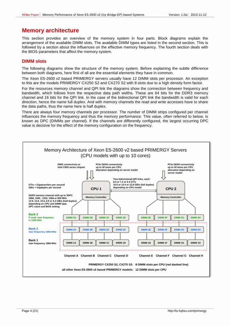
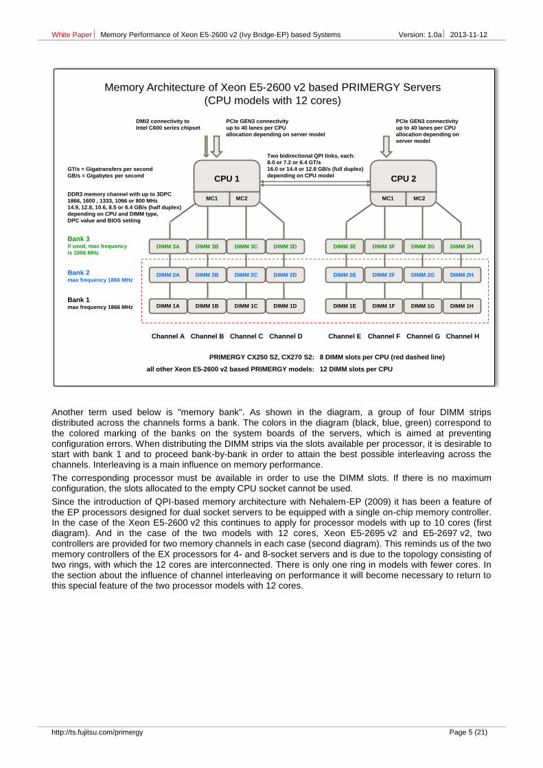
The following diagrams show the structure of the memory system. Before explaining the subtle difference between both diagrams, here first of all are the essential elements they have in common.
The Xeon E5-2600 v2 based PRIMERGY servers usually have 12 DIMM slots per processor. An exception to this are the models PRIMERGY CX250 S2 and CX270 S2 with 8 slots due to a high density form factor.
For the resources memory channel and QPI link the diagrams show the connection between frequency and bandwidth, which follows from the respective data path widths. These are 64 bits for the DDR3 memory channel and 16 bits for the QPI link. In the case of the bidirectional QPI link the bandwidth is valid for each direction, hence the name full duplex. And with memory channels the read and write accesses have to share the data paths, thus the name here is half duplex.
There are always four memory channels per processor. The number of DIMM strips configured per channel influences the memory frequency and thus the memory performance. This value, often referred to below, is known as DPC (DIMMs per channel). If the channels are differently configured, the largest occurring DPC value is decisive for the effect of the memory configuration on the frequency.
CPU 2
Memory Controller
DIMM 3E
DIMM 2E
DIMM 1E
DIMM 3F
DIMM 2F
DIMM 1F
DIMM 3H
DIMM 2H
DIMM 1H
Channel E
Bank 2max frequency 1866 MHz
Bank 3if used, max frequency
is 1066 MHz
Bank 1max frequency 1866 MHz
GT/s = Gigatransfers per second
GB/s = Gigabytes per second
DIMM 3G
DIMM 2G
DIMM 1G
Channel F Channel G Channel H
CPU 1
Memory Controller
DIMM 3A
DIMM 2A
DIMM 1A
DIMM 3B
DIMM 2B
DIMM 1B
DIMM 3D
DIMM 2D
DIMM 1D
Channel A
DIMM 3C
DIMM 2C
DIMM 1C
Channel B Channel C Channel D
Two bidirectional QPI links, each:
8.0 or 7.2 or 6.4 GT/s
16.0 or 14.4 or 12.8 GB/s (full duplex)
depending on CPU model
DDR3 memory channel with up to 3DPC
1866, 1600 , 1333, 1066 or 800 MHz
14.9, 12.8, 10.6, 8.5 or 6.4 GB/s (half duplex)
depending on CPU and DIMM type,
DPC value and BIOS setting
PCIe GEN3 connectivity
up to 40 lanes per CPU
allocation depending on server model
DMI2 connectivity to
Intel C600 series chipset
PCIe GEN3 connectivity
up to 40 lanes per CPU
allocation depending on
server model
PRIMERGY CX250 S2, CX270 S2:
all other Xeon E5-2600 v2 based PRIMERGY models:
8 DIMM slots per CPU (red dashed line)
12 DIMM slots per CPU
Memory Architecture of Xeon E5-2600 v2 based PRIMERGY Servers
(CPU models with up to 10 cores)
White Paper Memory Performance of Xeon E5-2600 v2 (Ivy Bridge-EP) based Systems Version: 1.0a 2013-11-12
http://ts.fujitsu.com/primergy Page 5 (21)
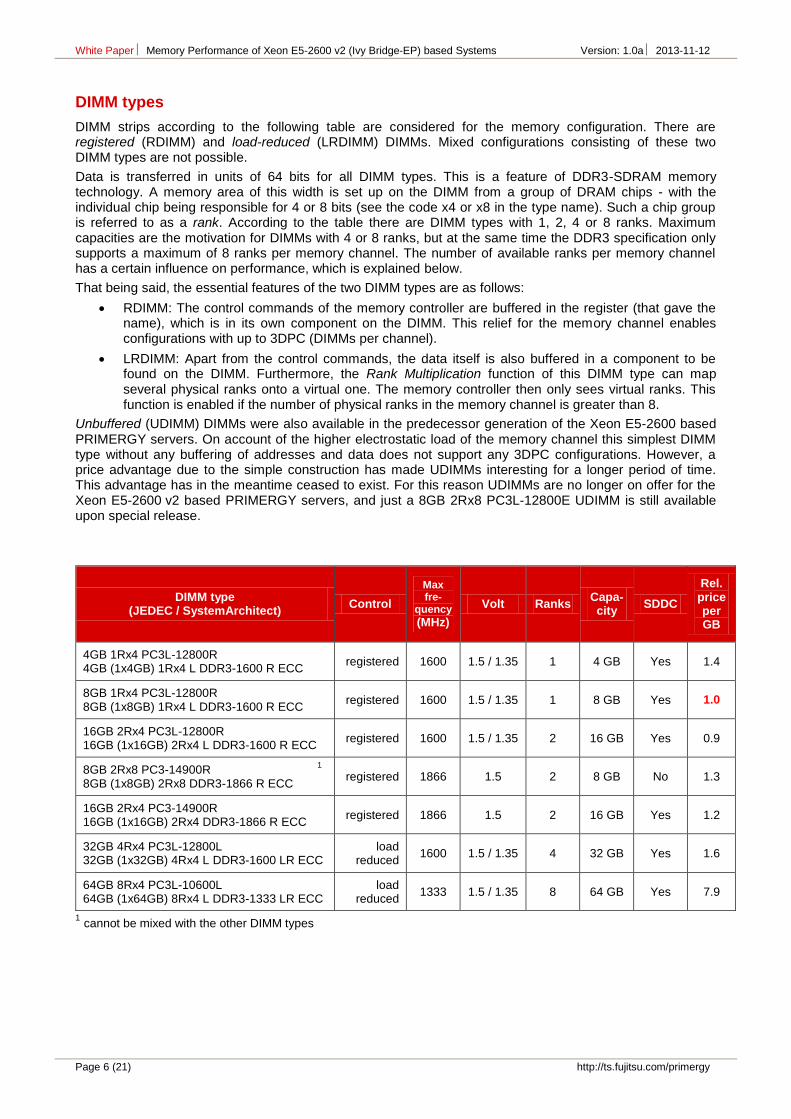
Another term used below is "memory bank". As shown in the diagram, a group of four DIMM strips distributed across the channels forms a bank. The colors in the diagram (black, blue, green) correspond to the colored marking of the banks on the system boards of the servers, which is aimed at preventing configuration errors. When distributing the DIMM strips via the slots available per processor, it is desirable to start with bank 1 and to proceed bank-by-bank in order to attain the best possible interleaving across the channels. Interleaving is a main influence on memory performance.
The corresponding processor must be available in order to use the DIMM slots. If there is no maximum configuration, the slots allocated to the empty CPU socket cannot be used.
Since the introduction of QPI-based memory architecture with Nehalem-EP (2009) it has been a feature of the EP processors designed for dual socket servers to be equipped with a single on-chip memory controller. In the case of the Xeon E5-2600 v2 this continues to apply for processor models with up to 10 cores (first diagram). And in the case of the two models with 12 cores, Xeon E5-2695 v2 and E5-2697 v2, two controllers are provided for two memory channels in each case (second diagram). This reminds us of the two memory controllers of the EX processors for 4- and 8-socket servers and is due to the topology consisting of two rings, with which the 12 cores are interconnected. There is only one ring in models with fewer cores. In the section about the influence of channel interleaving on performance it will become necessary to return to this special feature of the two processor models with 12 cores.
CPU 2
MC1 MC2
DIMM 3E
DIMM 2E
DIMM 1E
DIMM 3F
DIMM 2F
DIMM 1F
DIMM 3H
DIMM 2H
DIMM 1H
Channel E
Bank 2max frequency 1866 MHz
Bank 3if used, max frequency
is 1066 MHz
Bank 1max frequency 1866 MHz
GT/s = Gigatransfers per second
GB/s = Gigabytes per second
DIMM 3G
DIMM 2G
DIMM 1G
Channel F Channel G Channel H
CPU 1
MC1 MC2
DIMM 3A
DIMM 2A
DIMM 1A
DIMM 3B
DIMM 2B
DIMM 1B
DIMM 3D
DIMM 2D
DIMM 1D
Channel A
DIMM 3C
DIMM 2C
DIMM 1C
Channel B Channel C Channel D
Two bidirectional QPI links, each:
8.0 or 7.2 or 6.4 GT/s
16.0 or 14.4 or 12.8 GB/s (full duplex)
depending on CPU model
DDR3 memory channel with up to 3DPC
1866, 1600 , 1333, 1066 or 800 MHz
14.9, 12.8, 10.6, 8.5 or 6.4 GB/s (half duplex)
depending on CPU and DIMM type,
DPC value and BIOS setting
PCIe GEN3 connectivity
up to 40 lanes per CPU
allocation depending on server model
DMI2 connectivity to
Intel C600 series chipset
PCIe GEN3 connectivity
up to 40 lanes per CPU
allocation depending on
server model
PRIMERGY CX250 S2, CX270 S2:
all other Xeon E5-2600 v2 based PRIMERGY models:
8 DIMM slots per CPU (red dashed line)
12 DIMM slots per CPU
Memory Architecture of Xeon E5-2600 v2 based PRIMERGY Servers
(CPU models with 12 cores)
White Paper Memory Performance of Xeon E5-2600 v2 (Ivy Bridge-EP) based Systems Version: 1.0a 2013-11-12
Page 6 (21) http://ts.fujitsu.com/primergy
DIMM types
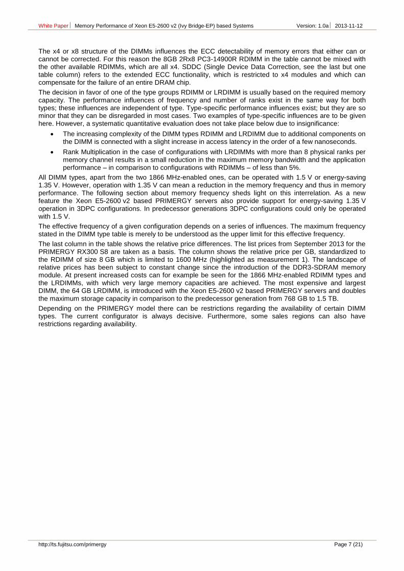
DIMM strips according to the following table are considered for the memory configuration. There are registered (RDIMM) and load-reduced (LRDIMM) DIMMs. Mixed configurations consisting of these two DIMM types are not possible.
Data is transferred in units of 64 bits for all DIMM types. This is a feature of DDR3-SDRAM memory technology. A memory area of this width is set up on the DIMM from a group of DRAM chips - with the individual chip being responsible for 4 or 8 bits (see the code x4 or x8 in the type name). Such a chip group is referred to as a rank. According to the table there are DIMM types with 1, 2, 4 or 8 ranks. Maximum capacities are the motivation for DIMMs with 4 or 8 ranks, but at the same time the DDR3 specification only supports a maximum of 8 ranks per memory channel. The number of available ranks per memory channel has a certain influence on performance, which is explained below.
That being said, the essential features of the two DIMM types are as follows:
RDIMM: The control commands of the memory controller are buffered in the register (that gave the name), which is in its own component on the DIMM. This relief for the memory channel enables configurations with up to 3DPC (DIMMs per channel).
LRDIMM: Apart from the control commands, the data itself is also buffered in a component to be found on the DIMM. Furthermore, the Rank Multiplication function of this DIMM type can map several physical ranks onto a virtual one. The memory controller then only sees virtual ranks. This function is enabled if the number of physical ranks in the memory channel is greater than 8.
Unbuffered (UDIMM) DIMMs were also available in the predecessor generation of the Xeon E5-2600 based PRIMERGY servers. On account of the higher electrostatic load of the memory channel this simplest DIMM type without any buffering of addresses and data does not support any 3DPC configurations. However, a price advantage due to the simple construction has made UDIMMs interesting for a longer period of time. This advantage has in the meantime ceased to exist. For this reason UDIMMs are no longer on offer for the Xeon E5-2600 v2 based PRIMERGY servers, and just a 8GB 2Rx8 PC3L-12800E UDIMM is still available upon special release.
DIMM type (JEDEC / SystemArchitect)
Control
Max fre-
quency (MHz)
Volt Ranks Capa-city
SDDC
Rel. price per GB
4GB 1Rx4 PC3L-12800R 4GB (1x4GB) 1Rx4 L DDR3-1600 R ECC
registered 1600 1.5 / 1.35 1 4 GB Yes 1.4
8GB 1Rx4 PC3L-12800R 8GB (1x8GB) 1Rx4 L DDR3-1600 R ECC
registered 1600 1.5 / 1.35 1 8 GB Yes 1.0
16GB 2Rx4 PC3L-12800R 16GB (1x16GB) 2Rx4 L DDR3-1600 R ECC
registered 1600 1.5 / 1.35 2 16 GB Yes 0.9
8GB 2Rx8 PC3-14900R 1
8GB (1x8GB) 2Rx8 DDR3-1866 R ECC registered 1866 1.5 2 8 GB No 1.3
16GB 2Rx4 PC3-14900R 16GB (1x16GB) 2Rx4 DDR3-1866 R ECC
registered 1866 1.5 2 16 GB Yes 1.2
32GB 4Rx4 PC3L-12800L 32GB (1x32GB) 4Rx4 L DDR3-1600 LR ECC
load reduced
1600 1.5 / 1.35 4 32 GB Yes 1.6
64GB 8Rx4 PC3L-10600L 64GB (1x64GB) 8Rx4 L DDR3-1333 LR ECC
load reduced
1333 1.5 / 1.35 8 64 GB Yes 7.9
1 cannot be mixed with the other DIMM types
White Paper Memory Performance of Xeon E5-2600 v2 (Ivy Bridge-EP) based Systems Version: 1.0a 2013-11-12
http://ts.fujitsu.com/primergy Page 7 (21)
The x4 or x8 structure of the DIMMs influences the ECC detectability of memory errors that either can or cannot be corrected. For this reason the 8GB 2Rx8 PC3-14900R RDIMM in the table cannot be mixed with the other available RDIMMs, which are all x4. SDDC (Single Device Data Correction, see the last but one table column) refers to the extended ECC functionality, which is restricted to x4 modules and which can compensate for the failure of an entire DRAM chip.
The decision in favor of one of the type groups RDIMM or LRDIMM is usually based on the required memory capacity. The performance influences of frequency and number of ranks exist in the same way for both types; these influences are independent of type. Type-specific performance influences exist; but they are so minor that they can be disregarded in most cases. Two examples of type-specific influences are to be given here. However, a systematic quantitative evaluation does not take place below due to insignificance:
The increasing complexity of the DIMM types RDIMM and LRDIMM due to additional components on the DIMM is connected with a slight increase in access latency in the order of a few nanoseconds.
Rank Multiplication in the case of configurations with LRDIMMs with more than 8 physical ranks per memory channel results in a small reduction in the maximum memory bandwidth and the application performance – in comparison to configurations with RDIMMs – of less than 5%.
All DIMM types, apart from the two 1866 MHz-enabled ones, can be operated with 1.5 V or energy-saving 1.35 V. However, operation with 1.35 V can mean a reduction in the memory frequency and thus in memory performance. The following section about memory frequency sheds light on this interrelation. As a new feature the Xeon E5-2600 v2 based PRIMERGY servers also provide support for energy-saving 1.35 V operation in 3DPC configurations. In predecessor generations 3DPC configurations could only be operated with 1.5 V.
The effective frequency of a given configuration depends on a series of influences. The maximum frequency stated in the DIMM type table is merely to be understood as the upper limit for this effective frequency.
The last column in the table shows the relative price differences. The list prices from September 2013 for the PRIMERGY RX300 S8 are taken as a basis. The column shows the relative price per GB, standardized to the RDIMM of size 8 GB which is limited to 1600 MHz (highlighted as measurement 1). The landscape of relative prices has been subject to constant change since the introduction of the DDR3-SDRAM memory module. At present increased costs can for example be seen for the 1866 MHz-enabled RDIMM types and the LRDIMMs, with which very large memory capacities are achieved. The most expensive and largest DIMM, the 64 GB LRDIMM, is introduced with the Xeon E5-2600 v2 based PRIMERGY servers and doubles the maximum storage capacity in comparison to the predecessor generation from 768 GB to 1.5 TB.
Depending on the PRIMERGY model there can be restrictions regarding the availability of certain DIMM types. The current configurator is always decisive. Furthermore, some sales regions can also have restrictions regarding availability.
White Paper Memory Performance of Xeon E5-2600 v2 (Ivy Bridge-EP) based Systems Version: 1.0a 2013-11-12
Page 8 (21) http://ts.fujitsu.com/primergy
Definition of the memory frequency
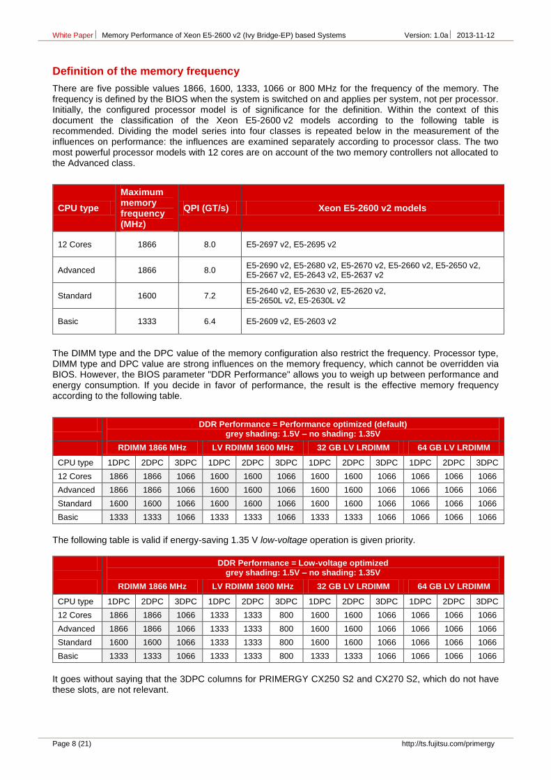
There are five possible values 1866, 1600, 1333, 1066 or 800 MHz for the frequency of the memory. The frequency is defined by the BIOS when the system is switched on and applies per system, not per processor. Initially, the configured processor model is of significance for the definition. Within the context of this document the classification of the Xeon E5-2600 v2 models according to the following table is recommended. Dividing the model series into four classes is repeated below in the measurement of the influences on performance: the influences are examined separately according to processor class. The two most powerful processor models with 12 cores are on account of the two memory controllers not allocated to the Advanced class.
The DIMM type and the DPC value of the memory configuration also restrict the frequency. Processor type, DIMM type and DPC value are strong influences on the memory frequency, which cannot be overridden via BIOS. However, the BIOS parameter "DDR Performance" allows you to weigh up between performance and energy consumption. If you decide in favor of performance, the result is the effective memory frequency according to the following table.
It goes without saying that the 3DPC columns for PRIMERGY CX250 S2 and CX270 S2, which do not have these slots, are not relevant.
White Paper Memory Performance of Xeon E5-2600 v2 (Ivy Bridge-EP) based Systems Version: 1.0a 2013-11-12
http://ts.fujitsu.com/primergy Page 9 (21)
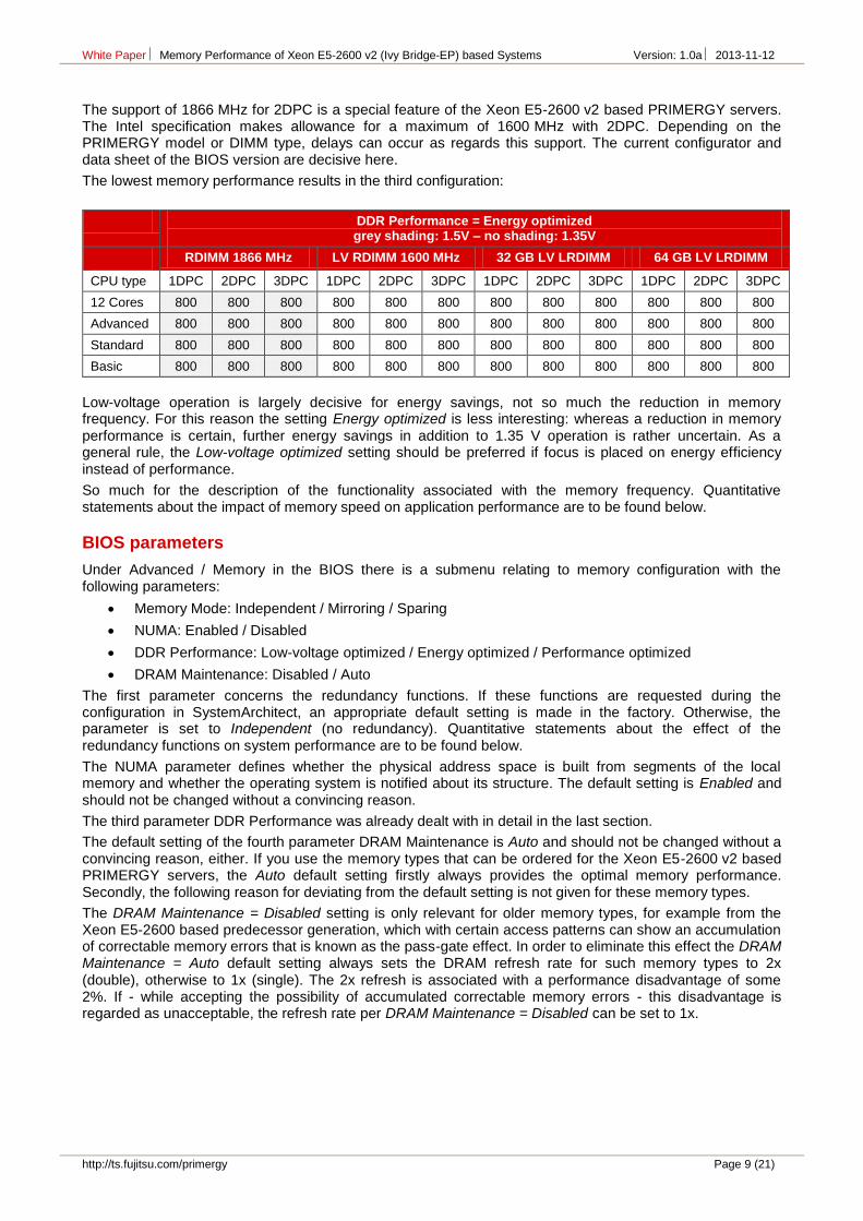
The support of 1866 MHz for 2DPC is a special feature of the Xeon E5-2600 v2 based PRIMERGY servers. The Intel specification makes allowance for a maximum of 1600 MHz with 2DPC. Depending on the PRIMERGY model or DIMM type, delays can occur as regards this support. The current configurator and data sheet of the BIOS version are decisive here.
The lowest memory performance results in the third configuration:
DDR Performance = Energy optimized grey shading: 1.5V – no shading: 1.35V
Low-voltage operation is largely decisive for energy savings, not so much the reduction in memory frequency. For this reason the setting Energy optimized is less interesting: whereas a reduction in memory performance is certain, further energy savings in addition to 1.35 V operation is rather uncertain. As a general rule, the Low-voltage optimized setting should be preferred if focus is placed on energy efficiency instead of performance.
So much for the description of the functionality associated with the memory frequency. Quantitative statements about the impact of memory speed on application performance are to be found below.
BIOS parameters
Under Advanced / Memory in the BIOS there is a submenu relating to memory configuration with the following parameters:
Memory Mode: Independent / Mirroring / Sparing
NUMA: Enabled / Disabled
DDR Performance: Low-voltage optimized / Energy optimized / Performance optimized
DRAM Maintenance: Disabled / Auto
The first parameter concerns the redundancy functions. If these functions are requested during the configuration in SystemArchitect, an appropriate default setting is made in the factory. Otherwise, the parameter is set to Independent (no redundancy). Quantitative statements about the effect of the redundancy functions on system performance are to be found below.
The NUMA parameter defines whether the physical address space is built from segments of the local memory and whether the operating system is notified about its structure. The default setting is Enabled and should not be changed without a convincing reason.
The third parameter DDR Performance was already dealt with in detail in the last section.
The default setting of the fourth parameter DRAM Maintenance is Auto and should not be changed without a convincing reason, either. If you use the memory types that can be ordered for the Xeon E5-2600 v2 based PRIMERGY servers, the Auto default setting firstly always provides the optimal memory performance. Secondly, the following reason for deviating from the default setting is not given for these memory types.
The DRAM Maintenance = Disabled setting is only relevant for older memory types, for example from the Xeon E5-2600 based predecessor generation, which with certain access patterns can show an accumulation of correctable memory errors that is known as the pass-gate effect. In order to eliminate this effect the DRAM Maintenance = Auto default setting always sets the DRAM refresh rate for such memory types to 2x (double), otherwise to 1x (single). The 2x refresh is associated with a performance disadvantage of some 2%. If - while accepting the possibility of accumulated correctable memory errors - this disadvantage is regarded as unacceptable, the refresh rate per DRAM Maintenance = Disabled can be set to 1x.
White Paper Memory Performance of Xeon E5-2600 v2 (Ivy Bridge-EP) based Systems Version: 1.0a 2013-11-12
Page 10 (21) http://ts.fujitsu.com/primergy
The following submenu then appears for the DRAM Maintenance = Disabled setting:
Patrol Scrub: Disabled / Enabled
Fast Patrol Scrub: Disabled / Enabled
Refresh Rate Multiplier: 1x / 2x / 3x / 4x
If the submenu is opened, the last one of these parameters is always preset with 2x (regardless of the configured memory types) and has the significance already described. By using the DRAM Maintenance = Disabled setting the user assumes responsibility for the correct parameter setting.
The Patrol Scrub parameter is preset with Enabled. The main memory is searched in cycles of 24 hours for correctable memory errors. This is a DRAM standard function that does not depend on the pass-gate effect. Highly sensitive performance measurements may be a reason for temporarily disabling this functionality. However, establishing proof of an effect on performance may be difficult.
Fast Patrol Scrub is preset with Disabled. Enabled in this case results in a reduction in the search cycles to about half an hour as a further precaution with regard to the pass-gate effect. However, intensive tests on PRIMERGY servers could not establish the need for a measure in excess of a double refresh, hence the Disabled default setting.
There is an explanation of all performance-relevant BIOS parameters of the Xeon E5-2600 v2 based PRIMERGY servers in [L6].
White Paper Memory Performance of Xeon E5-2600 v2 (Ivy Bridge-EP) based Systems Version: 1.0a 2013-11-12
http://ts.fujitsu.com/primergy Page 11 (21)
Performant memory configurations
The following statements on memory configurations are based on the terminology of the PRIMERGY configurator. The first section applies to configurations that utilize the topology of the memory system in an ideal way and provide the best memory performance. The configurator refers to them as Performance Mode configurations.
Performance Mode configurations
The configuration in this mode is on a bank-by-bank basis in groups of four DIMMs of the same type, thus treating all four memory channels of a processor equally. Memory access is equally distributed over these resources of the memory system. Technically speaking, the optimum 4-way interleaving is achieved via the memory channels.
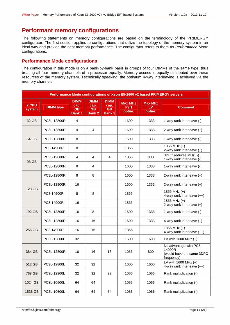
Performance Mode configurations of Xeon E5-2600 v2 based PRIMERGY servers
White Paper Memory Performance of Xeon E5-2600 v2 (Ivy Bridge-EP) based Systems Version: 1.0a 2013-11-12
Page 12 (21) http://ts.fujitsu.com/primergy
The above table lists configurations in Performance Mode sorted by memory capacity in an exemplary way. The table presumes two configured processors and the same memory configuration in both processors. Since the memory banks each consist of four DIMM slots of the same color per processor, the overall result is e.g. 32 GB if the first bank in both processors – i.e. eight DIMM slots – is configured with DIMM strips of size 4 GB. As to the DIMM types, refer to the table with the DIMM strips that are released for the Xeon E5-2600 v2 based PRIMERGY servers. The combination of DIMM type and capacity is in each case unique.
The table contains the maximum achievable memory frequency for the configuration, separated according to 1.5 V and energy-saving 1.35 V operation. However, whether these maximum frequencies are actually achieved also depends on the configured processor model. For example, the frequency 1866 MHz can only occur in the event of a configuration with processors from the model classes 12 Cores or Advanced.
The last column in the table provides an evaluation of what is better (+) or worse (-), especially for cases concerning the finishing touches of memory performance. See below for the details of the aforesaid features including quantitative effects (usually as a low single-digit percentage). The evaluation (++) was given in three cases, for configurations of the memory sizes 128, 256 and 512 GB. These are the configurations that are used in standard benchmarks for the Xeon E5-2600 v2 based PRIMERGY servers.
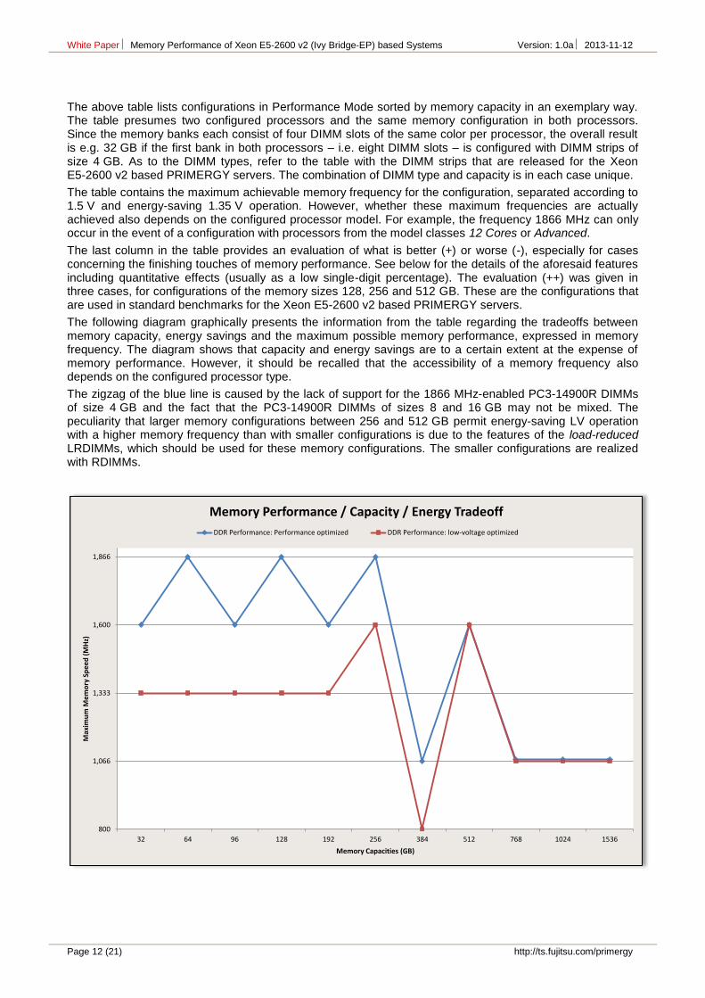
The following diagram graphically presents the information from the table regarding the tradeoffs between memory capacity, energy savings and the maximum possible memory performance, expressed in memory frequency. The diagram shows that capacity and energy savings are to a certain extent at the expense of memory performance. However, it should be recalled that the accessibility of a memory frequency also depends on the configured processor type.
The zigzag of the blue line is caused by the lack of support for the 1866 MHz-enabled PC3-14900R DIMMs of size 4 GB and the fact that the PC3-14900R DIMMs of sizes 8 and 16 GB may not be mixed. The peculiarity that larger memory configurations between 256 and 512 GB permit energy-saving LV operation with a higher memory frequency than with smaller configurations is due to the features of the load-reduced LRDIMMs, which should be used for these memory configurations. The smaller configurations are realized with RDIMMs.
White Paper Memory Performance of Xeon E5-2600 v2 (Ivy Bridge-EP) based Systems Version: 1.0a 2013-11-12
http://ts.fujitsu.com/primergy Page 13 (21)
Independent Mode configurations
This covers all the configurations that are neither in Performance Mode nor are redundant. Apart from the rule that
RDIMMs and LRDIMMs, and
RDIMMs of types x4 and x8
may not be mixed, there are no restrictions here.
Special attention is also given to configurations with less than four DIMMs per processor, i.e. less than the minimum number that is required for Performance Mode configurations. Apart from very low memory capacities, considerations about further energy savings can be the reason for such configurations. Savings do not merely result from 1.35 V operation and reducing the frequency of a given memory configuration, but also as a result of minimizing the number of DIMMs. The quantitative assessment that follows below of how a configuration of less than four memory channels impacts on system performance suggests the following recommendations:
In the case of processor classes Advanced, Standard and Basic operation with only one DIMM per processor is not to be recommended. Operation with two or three DIMMs per processor can on the other hand lead to balanced results as regards performance and energy consumption.
In the case of processor class 12 Cores operation with one or three DIMMs per processor is not to be recommended. Operation with two DIMMs per processor can on the other hand lead to balanced results as regards performance and energy consumption.
The non-recommended configurations mean entire (1 DIMM per processor) or partial (3 DIMMs per processor for the 12 Cores processors) 1-way interleaving via the memory channels with the clear performance disadvantage of up to 30%, as shown below, for the commercial application performance. The special feature of the 12 Cores processors follows from their configuration with two memory controllers with in each case two memory channels.
Symmetric memory configurations
Finally, a separate section is to once again highlight that all configured processors are to be equally configured with memory if possible and the NUMA = enabled default setting of the BIOS is not to be changed without a convincing reason. Only in this way is the QPI-based microarchitecture of the systems taken into consideration.
It goes without saying that preinstallation at the factory takes this circumstance into account. The ordered memory modules are distributed as equally as possible across the processors.
These measures and the related operating system support create the prerequisite to run applications as far as possible with a local, high-performance memory. The memory accesses of the processor cores are usually made to DIMM modules, which are directly allocated to the respective processor. In order to estimate what performance advantage this means, measurement results are listed below in the event that the memory of a 2-way server is indeed symmetrically configured, but where the BIOS option NUMA = disabled is set. Statistically, every second memory access is then made to a remote memory. The possible case for asymmetric or single-sided memory configuration that an application is run 100% with a remote memory should be estimated at the double loss in performance of the 50/50% case.
White Paper Memory Performance of Xeon E5-2600 v2 (Ivy Bridge-EP) based Systems Version: 1.0a 2013-11-12
Page 14 (21) http://ts.fujitsu.com/primergy
Quantitative effects on memory performance
After the functional description of the memory system with qualitative information, we now have specific statements about with which gain or loss in performance differences are connected in the memory configuration. As a means of preparation the first section deals with the two benchmarks that were used to characterize memory performance.
This is followed - in order of their impact - by the already mentioned features interleaving of the memory channels, memory frequency and interleaving of the ranks. At the end we then have measurements for the case of NUMA = disabled and memory performance under redundancy.
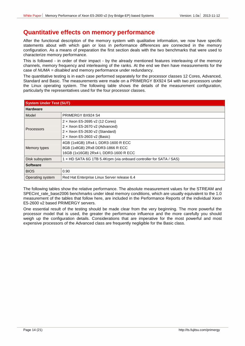
The quantitative testing is in each case performed separately for the processor classes 12 Cores, Advanced, Standard and Basic. The measurements were made on a PRIMERGY BX924 S4 with two processors under the Linux operating system. The following table shows the details of the measurement configuration, particularly the representatives used for the four processor classes.
System Under Test (SUT)
Hardware
Model PRIMERGY BX924 S4
Processors
2 × Xeon E5-2695 v2 (12 Cores)
2 × Xeon E5-2670 v2 (Advanced)
2 × Xeon E5-2630 v2 (Standard)
2 × Xeon E5-2603 v2 (Basic)
Memory types
4GB (1x4GB) 1Rx4 L DDR3-1600 R ECC
8GB (1x8GB) 2Rx8 DDR3-1866 R ECC
16GB (1x16GB) 2Rx4 L DDR3-1600 R ECC
Disk subsystem 1 × HD SATA 6G 1TB 5.4Krpm (via onboard controller for SATA / SAS)
Software
BIOS 0.90
Operating system Red Hat Enterprise Linux Server release 6.4
The following tables show the relative performance. The absolute measurement values for the STREAM and SPECint_rate_base2006 benchmarks under ideal memory conditions, which are usually equivalent to the 1.0 measurement of the tables that follow here, are included in the Performance Reports of the individual Xeon E5-2600 v2 based PRIMERGY servers.
One essential result of the testing should be made clear from the very beginning. The more powerful the processor model that is used, the greater the performance influence and the more carefully you should weigh up the configuration details. Considerations that are imperative for the most powerful and most expensive processors of the Advanced class are frequently negligible for the Basic class.
White Paper Memory Performance of Xeon E5-2600 v2 (Ivy Bridge-EP) based Systems Version: 1.0a 2013-11-12
http://ts.fujitsu.com/primergy Page 15 (21)
The measuring tools
Measurements were made using the benchmarks STREAM and SPECint_rate_base2006.
STREAM Benchmark
The STREAM benchmark from John McCalpin [L4] is a tool to measure memory throughput. The benchmark executes copy and calculation operations on large arrays of the data type double and it provides results for four access types: Copy, Scale, Add and Triad. The last three contain calculation operations. The result is always a throughput that is specified in GB/s. Triad values are quoted the most. All the STREAM measurement values specified in the following to quantify memory performance are based on this practice and are GB/s for the access type Triad.
STREAM is the industry standard for measuring the memory bandwidth of servers, known for its ability to put memory systems under immense stress using simple means. It is clear that this benchmark is particularly suitable for the purpose of studying effects on memory performance in a complex configuration space. In each situation STREAM shows the maximum effect on performance caused by a configuration action which affects the memory, be it deterioration or improvement. The percentages specified below regarding the STREAM benchmark are thus to be understood as bounds for performance effects.
The memory effect on application performance is differentiated between the latency of each access and the bandwidth required by the application. The quantities are interlinked, as real latency increases with increasing bandwidth. The scope in which the latency can be "hidden" by parallel memory access also depends on the application and the quality of the machine codes created by the compiler. As a result, making general forecasts for all application scenarios is very difficult.
SPECint_rate_base2006
The benchmark SPECint_rate_base2006 was added as a model for commercial application performance. It is part of SPECcpu2006 [L5] from Standard Performance Evaluation Corporation (SPEC). SPECcpu2006 is the industry standard for measuring the system components processor, memory hierarchy and compiler. According to the large volume of published results and their intensive use in sales projects and technical investigations this is the most important benchmark in the server field.
SPECcpu2006 consists of two independent suites of individual benchmarks, which differ in the predominant use of integer and floating-point operations. The integer part is representative for commercial applications and consists of 12 individual benchmarks. The floating-point part is representative for scientific applications and contains 17 individual benchmarks. The result of a benchmark run is in each case the geometric mean of the individual results.
A distinction is also made in the suites between the speed run with only one process and the rate run with a configurable number of processes working in parallel. The second version is evidently more interesting for servers with their large number of processor cores and hardware threads.
And finally a distinction is also made with regard to the permitted compiler optimization: for the peak result the individual benchmarks may be optimized independently of each other, but for the more conservative base result the compiler flags must be identical for all benchmarks, and certain optimizations are not permitted.
This explains what SPECint_rate_base2006 is about. The integer suite was selected, because commercial applications predominate in the use of PRIMERGY servers.
A measurement that is compliant with the regulations requires three runs, and the mean result is evaluated for each individual benchmark. This was not complied with in the technical investigation described here. To simplify matters only one run was performed at all times.
White Paper Memory Performance of Xeon E5-2600 v2 (Ivy Bridge-EP) based Systems Version: 1.0a 2013-11-12
Page 16 (21) http://ts.fujitsu.com/primergy
Interleaving across the memory channels
Interleaving in this conjunction is the set-up of the physical address area by alternating between the four memory channels per processor: the first block is in the first channel, the second in the second, etc. Memory access, which according to the locality principle is mainly to adjacent memory areas, is thus distributed across all channels. This performance gain situation results from parallelism. The blocking size of channel interleaving is based on the cache line size of 64 bytes, the unit of memory accesses from the point of view of the processor.
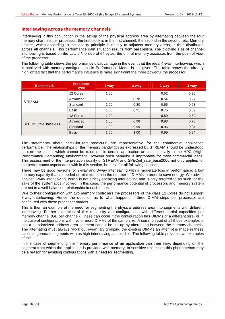
The following table shows the performance disadvantage in the event that the ideal 4-way interleaving, which is achieved with memory configurations in Performance Mode, is not given. The table shows the already highlighted fact that the performance influence is more significant the more powerful the processor.
Benchmark Processor
type 4-way 3-way 2-way 1-way
STREAM
12 Cores 1.00 0.52 0.26
Advanced 1.00 0.78 0.54 0.27
Standard 1.00 0.80 0.55 0.28
Basic 1.00 0.91 0.75 0.39
SPECint_rate_base2006
12 Cores 1.00 0.89 0.69
Advanced 1.00 0.98 0.93 0.76
Standard 1.00 0.99 0.96 0.84
Basic 1.00 1.00 0.99 0.94
The statements about SPECint_rate_base2006 are representative for the commercial application performance. The relationships of the memory bandwidth as expressed by STREAM should be understood as extreme cases, which cannot be ruled out in certain application areas, especially in the HPC (High-Performance Computing) environment. However such behavior is improbable for most commercial loads. This assessment of the interpretation quality of STREAM and SPECint_rate_base2006 not only applies for the performance aspect dealt with in this section, but also for all following sections.
There may be good reasons for 2-way and 3-way interleaving with a moderate loss in performance: a low memory capacity that is needed or minimization in the number of DIMMs in order to save energy. We advise against 1-way interleaving, which is not strictly speaking interleaving and is only referred to as such for the sake of the systematics involved. In this case, the performance potential of processors and memory system are not in a well-balanced relationship to each other.
Due to their configuration with two memory controllers the processors of the class 12 Cores do not support 3-way interleaving. Hence the question as to what happens if three DIMM strips per processor are configured with these processor models.
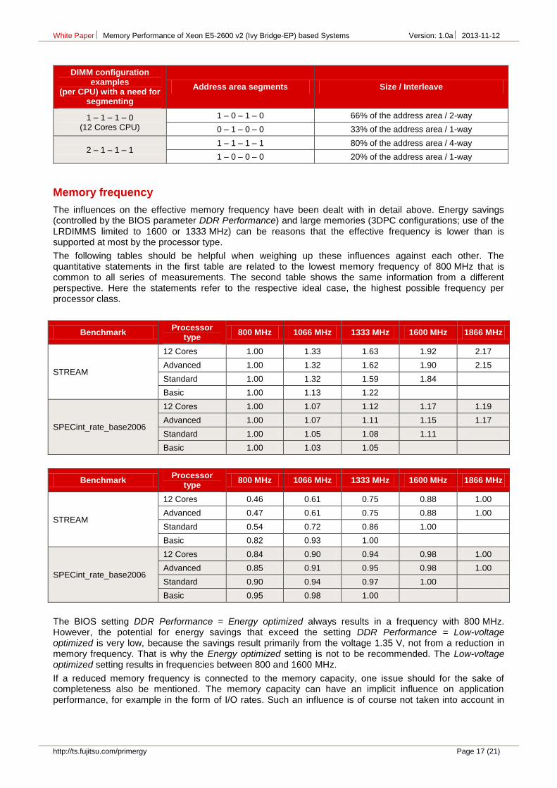
This is then an example of the need for segmenting the physical address area into segments with different interleaving. Further examples of this necessity are configurations with different partial capacities per memory channel (GB per channel). These can occur if the configuration has DIMMs of a different size, or in the case of configurations with five or more DIMMs of the same size. A common trait of all these examples is that a standardized address area segment cannot be set up by alternating between the memory channels. The alternating must always "work out even". By grouping the existing DIMMs an attempt is made in these cases to generate segments with as high interleaving as possible. The following table provides two examples of this.
In the case of segmenting the memory performance of an application can then vary, depending on the segment from which the application is provided with memory. In sensitive use cases this phenomenon may be a reason for avoiding configurations with a need for segmenting.
White Paper Memory Performance of Xeon E5-2600 v2 (Ivy Bridge-EP) based Systems Version: 1.0a 2013-11-12
http://ts.fujitsu.com/primergy Page 17 (21)
DIMM configuration examples
(per CPU) with a need for segmenting
Address area segments Size / Interleave
1 – 1 – 1 – 0 (12 Cores CPU)
1 – 0 – 1 – 0 66% of the address area / 2-way
0 – 1 – 0 – 0 33% of the address area / 1-way
2 – 1 – 1 – 1 1 – 1 – 1 – 1 80% of the address area / 4-way
1 – 0 – 0 – 0 20% of the address area / 1-way
Memory frequency
The influences on the effective memory frequency have been dealt with in detail above. Energy savings (controlled by the BIOS parameter DDR Performance) and large memories (3DPC configurations; use of the LRDIMMS limited to 1600 or 1333 MHz) can be reasons that the effective frequency is lower than is supported at most by the processor type.
The following tables should be helpful when weighing up these influences against each other. The quantitative statements in the first table are related to the lowest memory frequency of 800 MHz that is common to all series of measurements. The second table shows the same information from a different perspective. Here the statements refer to the respective ideal case, the highest possible frequency per processor class.
Benchmark Processor
type 800 MHz 1066 MHz 1333 MHz 1600 MHz 1866 MHz
STREAM
12 Cores 1.00 1.33 1.63 1.92 2.17
Advanced 1.00 1.32 1.62 1.90 2.15
Standard 1.00 1.32 1.59 1.84
Basic 1.00 1.13 1.22
SPECint_rate_base2006
12 Cores 1.00 1.07 1.12 1.17 1.19
Advanced 1.00 1.07 1.11 1.15 1.17
Standard 1.00 1.05 1.08 1.11
Basic 1.00 1.03 1.05
Benchmark Processor
type 800 MHz 1066 MHz 1333 MHz 1600 MHz 1866 MHz
STREAM
12 Cores 0.46 0.61 0.75 0.88 1.00
Advanced 0.47 0.61 0.75 0.88 1.00
Standard 0.54 0.72 0.86 1.00
Basic 0.82 0.93 1.00
SPECint_rate_base2006
12 Cores 0.84 0.90 0.94 0.98 1.00
Advanced 0.85 0.91 0.95 0.98 1.00
Standard 0.90 0.94 0.97 1.00
Basic 0.95 0.98 1.00
The BIOS setting DDR Performance = Energy optimized always results in a frequency with 800 MHz. However, the potential for energy savings that exceed the setting DDR Performance = Low-voltage optimized is very low, because the savings result primarily from the voltage 1.35 V, not from a reduction in memory frequency. That is why the Energy optimized setting is not to be recommended. The Low-voltage optimized setting results in frequencies between 800 and 1600 MHz.
If a reduced memory frequency is connected to the memory capacity, one issue should for the sake of completeness also be mentioned. The memory capacity can have an implicit influence on application performance, for example in the form of I/O rates. Such an influence is of course not taken into account in
White Paper Memory Performance of Xeon E5-2600 v2 (Ivy Bridge-EP) based Systems Version: 1.0a 2013-11-12
Page 18 (21) http://ts.fujitsu.com/primergy
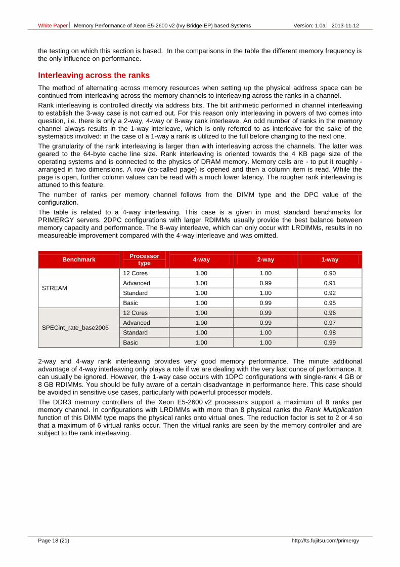
the testing on which this section is based. In the comparisons in the table the different memory frequency is the only influence on performance.
Interleaving across the ranks
The method of alternating across memory resources when setting up the physical address space can be continued from interleaving across the memory channels to interleaving across the ranks in a channel.
Rank interleaving is controlled directly via address bits. The bit arithmetic performed in channel interleaving to establish the 3-way case is not carried out. For this reason only interleaving in powers of two comes into question, i.e. there is only a 2-way, 4-way or 8-way rank interleave. An odd number of ranks in the memory channel always results in the 1-way interleave, which is only referred to as interleave for the sake of the systematics involved: in the case of a 1-way a rank is utilized to the full before changing to the next one.
The granularity of the rank interleaving is larger than with interleaving across the channels. The latter was geared to the 64-byte cache line size. Rank interleaving is oriented towards the 4 KB page size of the operating systems and is connected to the physics of DRAM memory. Memory cells are - to put it roughly - arranged in two dimensions. A row (so-called page) is opened and then a column item is read. While the page is open, further column values can be read with a much lower latency. The rougher rank interleaving is attuned to this feature.
The number of ranks per memory channel follows from the DIMM type and the DPC value of the configuration.
The table is related to a 4-way interleaving. This case is a given in most standard benchmarks for PRIMERGY servers. 2DPC configurations with larger RDIMMs usually provide the best balance between memory capacity and performance. The 8-way interleave, which can only occur with LRDIMMs, results in no measureable improvement compared with the 4-way interleave and was omitted.
Benchmark Processor
type 4-way 2-way 1-way
STREAM
12 Cores 1.00 1.00 0.90
Advanced 1.00 0.99 0.91
Standard 1.00 1.00 0.92
Basic 1.00 0.99 0.95
SPECint_rate_base2006
12 Cores 1.00 0.99 0.96
Advanced 1.00 0.99 0.97
Standard 1.00 1.00 0.98
Basic 1.00 1.00 0.99
2-way and 4-way rank interleaving provides very good memory performance. The minute additional advantage of 4-way interleaving only plays a role if we are dealing with the very last ounce of performance. It can usually be ignored. However, the 1-way case occurs with 1DPC configurations with single-rank 4 GB or 8 GB RDIMMs. You should be fully aware of a certain disadvantage in performance here. This case should be avoided in sensitive use cases, particularly with powerful processor models.
The DDR3 memory controllers of the Xeon E5-2600 v2 processors support a maximum of 8 ranks per memory channel. In configurations with LRDIMMs with more than 8 physical ranks the Rank Multiplication function of this DIMM type maps the physical ranks onto virtual ones. The reduction factor is set to 2 or 4 so that a maximum of 6 virtual ranks occur. Then the virtual ranks are seen by the memory controller and are subject to the rank interleaving.
White Paper Memory Performance of Xeon E5-2600 v2 (Ivy Bridge-EP) based Systems Version: 1.0a 2013-11-12
http://ts.fujitsu.com/primergy Page 19 (21)
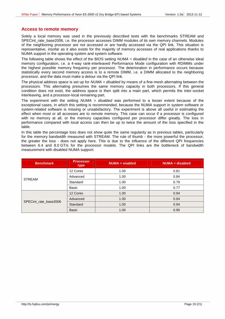
Access to remote memory
Solely a local memory was used in the previously described tests with the benchmarks STREAM and SPECint_rate_base2006, i.e. the processor accesses DIMM modules of its own memory channels. Modules of the neighboring processor are not accessed or are hardly accessed via the QPI link. This situation is representative, insofar as it also exists for the majority of memory accesses of real applications thanks to NUMA support in the operating system and system software.
The following table shows the effect of the BIOS setting NUMA = disabled in the case of an otherwise ideal memory configuration, i.e. a 4-way rank-interleaved Performance Mode configuration with RDIMMs under the highest possible memory frequency per processor. The deterioration in performance occurs because statistically every second memory access is to a remote DIMM, i.e. a DIMM allocated to the neighboring processor, and the data must make a detour via the QPI link.
The physical address space is set up for NUMA = disabled by means of a fine-mesh alternating between the processors. This alternating presumes the same memory capacity in both processors. If this general condition does not exist, the address space is then split into a main part, which permits the inter-socket interleaving, and a processor-local remaining part.
The experiment with the setting NUMA = disabled was performed to a lesser extent because of the exceptional cases, in which this setting is recommended, because the NUMA support in system software or system-related software is missing or unsatisfactory. The experiment is above all useful in estimating the effect when most or all accesses are to remote memory. This case can occur if a processor is configured with no memory at all, or the memory capacities configured per processor differ greatly. The loss in performance compared with local access can then be up to twice the amount of the loss specified in the table.
In this table the percentage loss does not show quite the same regularity as in previous tables, particularly for the memory bandwidth measured with STREAM. The rule of thumb - the more powerful the processor, the greater the loss - does not apply here. This is due to the influence of the different QPI frequencies between 6.4 and 8.0 GT/s for the processor models. The QPI links are the bottleneck of bandwidth measurement with disabled NUMA support.
Benchmark Processor
type NUMA = enabled NUMA = disabled
STREAM
12 Cores 1.00 0.81
Advanced 1.00 0.84
Standard 1.00 0.79
Basic 1.00 0.77
SPECint_rate_base2006
12 Cores 1.00 0.94
Advanced 1.00 0.94
Standard 1.00 0.94
Basic 1.00 0.95
White Paper Memory Performance of Xeon E5-2600 v2 (Ivy Bridge-EP) based Systems Version: 1.0a 2013-11-12
Page 20 (21) http://ts.fujitsu.com/primergy
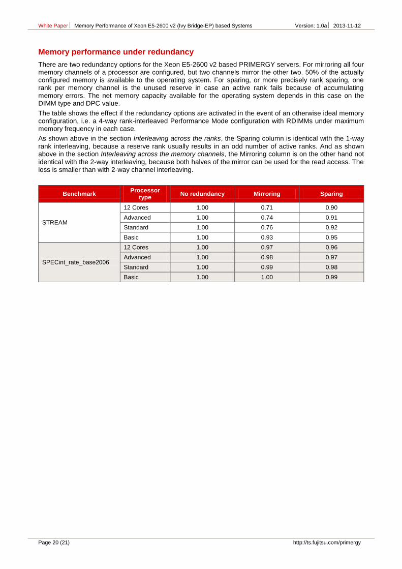
Memory performance under redundancy
There are two redundancy options for the Xeon E5-2600 v2 based PRIMERGY servers. For mirroring all four memory channels of a processor are configured, but two channels mirror the other two. 50% of the actually configured memory is available to the operating system. For sparing, or more precisely rank sparing, one rank per memory channel is the unused reserve in case an active rank fails because of accumulating memory errors. The net memory capacity available for the operating system depends in this case on the DIMM type and DPC value.
The table shows the effect if the redundancy options are activated in the event of an otherwise ideal memory configuration, i.e. a 4-way rank-interleaved Performance Mode configuration with RDIMMs under maximum memory frequency in each case.
As shown above in the section Interleaving across the ranks, the Sparing column is identical with the 1-way rank interleaving, because a reserve rank usually results in an odd number of active ranks. And as shown above in the section Interleaving across the memory channels, the Mirroring column is on the other hand not identical with the 2-way interleaving, because both halves of the mirror can be used for the read access. The loss is smaller than with 2-way channel interleaving.
Benchmark Processor
type No redundancy Mirroring Sparing
STREAM
12 Cores 1.00 0.71 0.90
Advanced 1.00 0.74 0.91
Standard 1.00 0.76 0.92
Basic 1.00 0.93 0.95
SPECint_rate_base2006
12 Cores 1.00 0.97 0.96
Advanced 1.00 0.98 0.97
Standard 1.00 0.99 0.98
Basic 1.00 1.00 0.99
White Paper Memory Performance of Xeon E5-2600 v2 (Ivy Bridge-EP) based Systems Version: 1.0a 2013-11-12
http://ts.fujitsu.com/primergy Page 21 (21)
Literature
PRIMERGY Systems
[L1] http://primergy.com/
Memory Performance
[L2] This White Paper http://docs.ts.fujitsu.com/dl.aspx?id=a344b05e-2e9d-481b-8c9b-c6542defd839 http://docs.ts.fujitsu.com/dl.aspx?id=9c2f6975-753c-47b8-821a-b54caf030979 http://docs.ts.fujitsu.com/dl.aspx?id=43d136df-46f6-443f-9f79-56466daddd1d
[L3] Memory Performance of Xeon E5-2600 (Sandy Bridge-EP) based Systems http://docs.ts.fujitsu.com/dl.aspx?id=a17dbb55-c43f-4ac8-886a-7950cb27ec2a