Memory Upgrade for the
Fanuc 16B (0010) Series CNC
FROM Module Installation
Installation Instructions
Memex Automation Inc. 200 – 3425 Harvester Rd.,
Burlington, Ontario Canada L7N 3N1 Phone: 905-635-3040 Fax: 905-631-9640
©2011 Memex Automation Inc. All rights reserved.
Memex does not assume liability for the use of this manual.
2
Table of Contents
Introduction.............................................................................. 4
Installation Considerations.................................................. 4
About This Manual............................................................. 4
Installing the Memex Memory Upgrade.................................. 6
Backup All Parameters........................................................ 6
Backup to SRAM Memory PC Card.................................... 6
Record Settings & Options................................................. 10
Backup to Computer........................................................... 11
Upgrade Memory Size Option Parameters........................... 13
Fanuc CPU Card Layout Examples..................................... 14
Install the New Memory Module........................................ 15
Restore the Control............................................................. 16
Verify the Control.............................................................. 21
Installation Checklist.......................................................... 22
Fanuc 16 Technical Summary............................................... 23
Memex Technical Support & Service.................................... 26
Appendix A: Parameter Records........................................... 28
3
Fanuc 16B Control CPU Card (0010 CPU Card is 2nd
from right in
this picture beside the power supply)
4
Introduction
Thank you for purchasing the Memex Memory Upgrade Kit for the Fanuc
16B series control. At Memex we invest a great deal of effort in the
design, manufacture and testing of each unit we build, and back it with a
three-year limited warranty. We are confident you will find this upgrade
significantly improves your CNC machining operations.
General Information
The installation procedure is straightforward and relatively easy to
complete – backup the parameters and programs, swap the memory
module, and restore the parameters and programs. All that’s needed are
some basic skills and hand tools. Estimated time required: 1 hour.
The 16B with the Main CPU card of A16B-3200-0010 can be upgraded
to 2.25MB (5120 meters) + up to 8 Megs of FLASH System Read Only
Memory (FROM). The memory is resident on a Single In-Line Memory
Module or “SIMM” that is located on the Main CPU board in slot 1
(top left if board is removed and connector to motherboard is on the
left). This “CPU” board is one of the grey slots in the yellow plastic
box, next to the power supply at the right side. The CPU board, once
removed, can keep the SIMM powered for over 30 minutes via a
“MAXCAP” backup capacitor.
IMPORTANT:
Please see “Applicable CPU Boards” on page 16. This SIMM must not
be installed in any other CPU board not listed in the table. If the
intended CPU board is not A16B-3200-0010, please contact Memex
Technical Support.
5
Installation Considerations The memory upgrade should be conducted with care. Never install or
remove a board with the control power on (the main power can be on,
but not the control). Take care when handling circuit boards, as they are
static sensitive. Keep the boards in the anti-static bag provided. Do not
place the SIMM in any other slot on the Fanuc CPU board. Do not
force, drop or otherwise mishandle the boards during the installation
procedure.
About this Manual
This manual explains how to install the Memex Memory Upgrade Kit
for the Fanuc 16B (0010 CPU card) control only, and consists of the
following sections:
Installing the Memex Memory Upgrade explains how to install the
Memex Memory Upgrade Kit into the Fanuc 16B CNC. It consists of
sections regarding backing up the control’s memory contents to both a
memory PC card (formerly known as a “PCMCIA” card) and a
computer, removing the existing CNC memory module and installing
the new one, changing some settings to use the new memory size, and
restoring and verifying the control.
Fanuc 16 & 18 Technical Summary provides brief summaries of the
procedures to punch and read data, critical parameters and their
settings, serial port and cable configuration information, applicable
CPU boards and memory modules, and PC card backup file naming
conventions.
Technical Support provides contact information for technical support
and customer service.
Appendix A: Parameter Records provides tables for manually
recording critical parameters before performing the memory upgrade.
These parameters must be re-entered manually before restoring the
parameter backups after the memory upgrade. It is critical that they be
copied down accurately.
6
Installing the Memex Memory Upgrade
Backup All Parameters
For the 16B control, 4 Meg PCMCIA SRAM card is required (sold
separately) that will allow you to easily backup your existing CNC
settings. This optional 4 Meg SRAM card can be purchased from
Memex, if required. The process backs up all parameters into non-
volatile memory on the card. The card may then be kept as a safety
backup of the pre-upgrade configuration in case a quick reversal of the
upgrade is ever required, or updated after the upgrade to facilitate a
quick restore of the new configuration in the event of any parameter
change or loss.
Backup to SRAM PCMCIA Card
Before starting the installation, power on the control and verify that the
machine tool is in good working order. If the control has an SRAM
system error and is inoperable, then you will have to replace your
SIMM with the new one, and restore the information from existing
parameter backups. Please read the attached Addendum at this time.
1. Home the machine before performing the memory upgrade.
2. Insert the 4 Meg SRAM PC card into the main CPU (A16B-3200-
0010) slot 1, facing left. It goes in only a short way and can be
done with the power ON or OFF.
3. Power ON the control holding down the right-most soft key and the
7th
soft key to its left counting the right-most key as 1. It is usually
the other Chapter key (except with colour monitors) under the
monitor. The SYSTEM MONITOR SERVICE MENU screen
should appear.
7
Main IPL Screen When Powered Up Holding Right
Soft Key (Under Monitor) and 7th
from Right
4. If the card has not been used in a Fanuc before, use the soft key
{DOWN] and optionally select #5 to format it. (Do NOT select 8.
FLASH ROM INITIALIZE as all system files will be lost.)
5. Select the SRAM DATA BACKUP line and press SELECT to
change to the Backup screen.
Note: If the CNC has an Option board that also has SRAM, it needs to
be backed up as well. An intermediate menu will appear in this case.
Select each line and backup up the files indicated (if present).
Sample Optional Intermediate SRAM Backup Menu
BOOT SLOT CONFIGURATION 60M1-09
NO. BOARD F-ROM SRAM
0. MAIN 6MB 0.5 MB
3. OPT3 128 KB
4. LCB 512 KB
*** MESSAGE ***
SELECT SLOT AND HIT SELECT KEY
SELECT YES NO UP DOWN
8
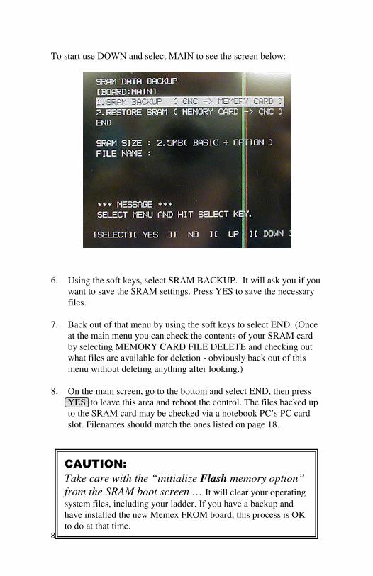
To start use DOWN and select MAIN to see the screen below:
6. Using the soft keys, select SRAM BACKUP. It will ask you if you
want to save the SRAM settings. Press YES to save the necessary
files.
7. Back out of that menu by using the soft keys to select END. (Once
at the main menu you can check the contents of your SRAM card
by selecting MEMORY CARD FILE DELETE and checking out
what files are available for deletion - obviously back out of this
menu without deleting anything after looking.)
8. On the main screen, go to the bottom and select END, then press
YES to leave this area and reboot the control. The files backed up
to the SRAM card may be checked via a notebook PC’s PC card
slot. Filenames should match the ones listed on page 18.
CAUTION:
Take care with the “initialize Flash memory option”
from the SRAM boot screen … It will clear your operating
system files, including your ladder. If you have a backup and
have installed the new Memex FROM board, this process is OK
to do at that time.
9
9. Once you have safely backed up the SRAM onto a laptop, proceed
to backup the firmware double-checking that all files are accounted
for. Use Item 4. SYSTEM DATA SAVE.
This may take several reloads on the PCMCIA SRAM card as it
can only handle 4, 6 or 8 Megs of the possible 8 Megs + 2.25 Meg
SRAM backup you need to do. Make sure your computer can read
the PCMCIA Type II SRAM card first!
From SYSTEM DATA SAVE Screen proceed to backup each file separately. You may have to move files from the PCMCIA SRAM card to your laptop to
complete this step.
NOTE:
When you remove the old FROM board you will not lose the FLASH
System files, only the Additional SRAM (if present on the board).
The Fanuc 16MB with the 0010 CPU card has 256k of battery backed
SRAM on the main CPU card, then the FROM module has additional
memory.
The PCMCIA SRAM backup procedure is very secure, just make sure
that you have a copy of the 9000 macro programs (you may have to
unprotect them with parameter P3202.4 and P3202.0 to 0 to unprotect
part programs in the 8000 and 9000 series)
10
Optional Record Settings & Options
Settings
1. Using the forms on page 28, record the SETTING (“Handy”)
screen data. (To display the parameters, Press the SYSTEM ,
PARAM soft keys. To skip to specific parameters, enter the
number of the parameter to be displayed and press NO.SRH. The
screen can also be changed using the cursor or page key.)
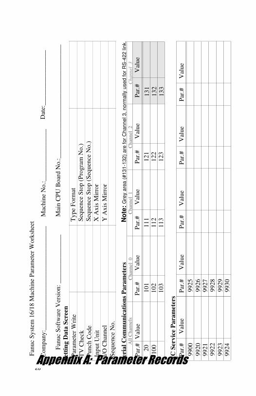
2. Write down the serial port settings in parameters 20, 100-103, 111-
113 and 121-123. (131-133 if using Channel 3, i.e. RS-422 link.)
3. Using the forms on pages 22-26, record the NC Service
Parameters, PC Parameters, and Data Tables.
Fanuc RoboDrills often need Memex FROM boards.
11
Optional Manual Backup to Computer
1. If not already connected, connect the CNC to a PC with a serial
data cable (see “Standard Fanuc Serial Cable”, page 24). You will
need a communications program (such as a DNC system or at least
a terminal program) to download and upload the parameters. Make
sure the software’s communications settings match the CNC’s. NC Parameters
2. Get the computer ready to receive the NC data.
• Select EDIT mode.
• Press softkeys SYSTEM PARAM OPTR > PUNCH EXEC
Pitch Error Compensation
3. Get the computer ready to receive the Pitch Error Comp. data.
• Confirm that EDIT mode is selected.
• Press SYSTEM > PITCH OPTR > PUNCH EXEC Macro Variables
4. Get the computer ready to receive the macro variables.
• Confirm that EDIT mode is selected.
• Press OFFSET > MACRO OPTR > PUNCH EXEC
Part Programs
5. Set parameter 3202.4 and 3202.0 to 0 to unprotect part programs in
the 8000 series and 9000 series. Get the computer ready to receive
part programs.
• Confirm that EDIT mode is selected.
• Press PRGRM > .
• Type O-9999 and press PUNCH EXEC .
Tool & Work Offsets
6. Get the computer ready to receive the Tool Offset data.
• Confirm that EDIT mode is selected.
• Press OFFSET OPTR > PUNCH EXEC .
Get the computer ready to receive the Work Offset data.
• Confirm that EDIT mode is selected.
• Press WORK OPTR > PUNCH EXEC .
12
PMC Data
7. The PMC communications settings are separate from the normal
serial port settings. Set them to match the settings for other serial
communications so the PMC data can be easily backed up.
To set the communications settings and output the data:
• Select MDI mode.
• Press OFFSET/SETTING , then the SETTING softkey.
• Cursor to PARAMETER WRITE and input a 1. Ignore alarm.
• Press SYSTEM key, then softkeys PMC PMCPRM KEEPRL .
• Cursor to K17 and set bit 1 to 1 (change no other bits).
• Select EDIT mode.
• Press < > I/O .
• Set the parameters to match those of the normal I/O channel.
• Fort CHANNEL NO, input 1 for channel 1.
• For DEVICE, press softkey FDCAS .
• For KIND DATA, press softkey PARAM .
• For FUNCTION, press softkey WRITE .
• For FILE No, enter the file name @PMC and press INPUT .
• Press softkey EXEC. The PMC parameters will be output.
• After output finishes, set PARAMETER WRITE back to 0 .
• Press RESET to release alarm 100.
Once downloaded this PMC file must be edited before it can be
reloaded. Load the file just downloaded into an editor and delete the 12
or so characters before the first percent sign (these are feed characters
and will cause a 930 System Alarm when file is reloaded).
Also backup CAP data and Graphics & Animation parameters if
present: Edit mode, press OFFSET key, then CAP TL > PUNCH .
NOTE: On some Makino machines the PMC parameters may be
locked with LOCK RELEASE. Type MSYS or PRO then INPUT.
Also on some Makino machines the M231 code can be used to copy
the PMC data into program 06666.
· In MDI mode, press PROGRAM M 2 3 1 INSERT
· Press CUSTOM then PARAM or MS
· Press MENU PAGE then LOCK RELEASE
· Type P R O or M S Y S then INPUT
· Press CYCLE START
The PMC data will now be written to part program O6666. Backup
this program to the computer the same way as other part programs.
13
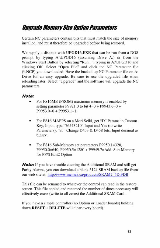
Upgrade Memory Size Option Parameters
Certain NC parameters contain bits that must match the size of memory
installed, and must therefore be upgraded before being restored.
We supply a diskette with UPGD16.EXE that can be run from a DOS
prompt by typing A:\UPGD16 (assuming Drive A:) or from the
Windows Start Button by selecting “Run...”, typing in A:\UPGD16 and
clicking OK. Select “Open File” and click the NC Parameter file
(*.NCP) you downloaded. Have the backed up NC Parameter file on A:
Drive for an easy upgrade. Be sure to use the upgraded file when
reloading later. Select “Upgrade” and the software will upgrade the NC
parameters.
Note:
• For FS16MB (FROM) maximum memory is enabled by
setting parameter P9921.0 to bit 4=0 + P9943.6=0 +
P9953.0=0 + P9953.1=1.
• For FS16 MAPPS on a Mori Seiki, get “D” Params in Custom
Key, Input, type “76543210” Input and Yes (to write
Parameters), “95” Change D453 & D458 bits, Input decimal as
binary.
• For FS16 Sub-Memory set parameters P9950.1=320,
P9950.0=640, P9950.5=1280 + P9949.7=Add. Sub-Memory
for PP/S Edit2 Option
Note: If you have trouble clearing the Additional SRAM and still get
Parity Alarms, you can download a blank 512k SRAM backup file from
our web site at: http://www.memex.ca/products/SRAM2_5D.FDB
This file can be renamed to whatever the control can read in the restore
screen. This file copied and renamed the number of times necessary will
effectively erase (write to all zeros) the Additional SRAM Card.
If you have a simple controller (no Option or Loader boards) holding
down RESET + DELETE will clear every board).
14
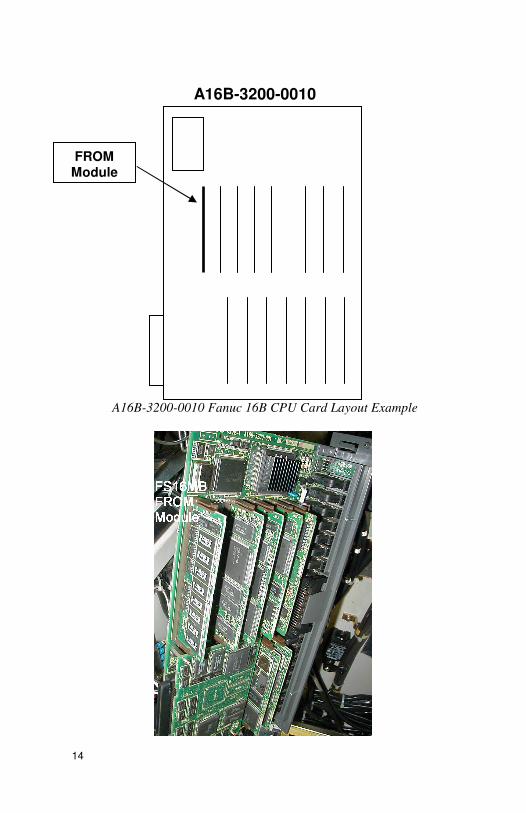
A16B-3200-0010 Fanuc 16B CPU Card Layout Example
FROM Module
A16B-3200-0010
15
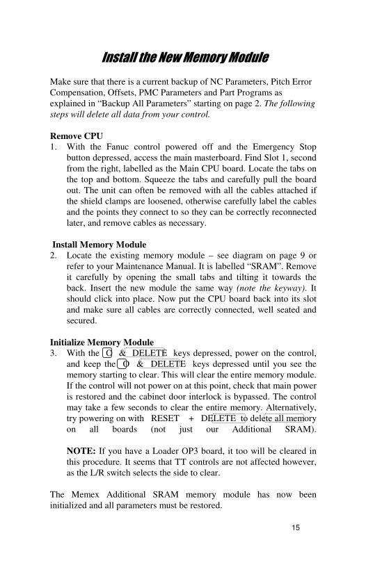
Install the New Memory Module
Make sure that there is a current backup of NC Parameters, Pitch Error
Compensation, Offsets, PMC Parameters and Part Programs as
explained in “Backup All Parameters” starting on page 2. The following
steps will delete all data from your control.
Remove CPU
1. With the Fanuc control powered off and the Emergency Stop
button depressed, access the main masterboard. Find Slot 1, second
from the right, labelled as the Main CPU board. Locate the tabs on
the top and bottom. Squeeze the tabs and carefully pull the board
out. The unit can often be removed with all the cables attached if
the shield clamps are loosened, otherwise carefully label the cables
and the points they connect to so they can be correctly reconnected
later, and remove cables as necessary.
Install Memory Module
2. Locate the existing memory module – see diagram on page 9 or
refer to your Maintenance Manual. It is labelled “SRAM”. Remove
it carefully by opening the small tabs and tilting it towards the
back. Insert the new module the same way (note the keyway). It
should click into place. Now put the CPU board back into its slot
and make sure all cables are correctly connected, well seated and
secured.
Initialize Memory Module
3. With the O & DELETE keys depressed, power on the control,
and keep the O & DELETE keys depressed until you see the
memory starting to clear. This will clear the entire memory module.
If the control will not power on at this point, check that main power
is restored and the cabinet door interlock is bypassed. The control
may take a few seconds to clear the entire memory. Alternatively,
try powering on with RESET + DELETE to delete all memory
on all boards (not just our Additional SRAM).
NOTE: If you have a Loader OP3 board, it too will be cleared in
this procedure. It seems that TT controls are not affected however,
as the L/R switch selects the side to clear.
The Memex Additional SRAM memory module has now been
initialized and all parameters must be restored.
16
Restore The Control
Restore Settings & Options
Before restoring parameters from backup copy, some of the parameters
recorded on pages 28-32 must be restored manually. Enter SETTING
(“Handy”) screen data and serial communications parameters.
Restore From SRAM PC Card or from Computer
The remaining parameters may be restored from either the SRAM PC
card or the computer. Choose one of the following two options:
Option 1: Restore From SRAM PC Card
1. Before the files on the SRAM card can be restored, they must be
renamed to correspond to the new memory size. See page 25 for
naming conventions and instructions on renaming the backup files.
2. Insert the SRAM card into the main CPU slot 1, with the face
pointing left. It goes in only a short way and can be done with the
power ON or OFF.
3. Power ON the control holding down the two right-most soft keys
under the monitor. The SYSTEM MONITOR SERVICE MENU
screen should appear.
4. Select the SRAM DATA RESTORE line to change to the Restore
screen.
10. Cursor to and select RESTORE SRAM. Press YES to restore the
files.
11. Back out of that menu by using the soft keys to select END.
On the main screen, go to the bottom and select END, then press
YES to leave this area and reboot the control.
CAUTION: Never initialize the Flash memory from the SRAM
boot screen. - It will clear your operating system files, including your ladder.
It is OK to initialize the SRAM card however. To see the files already on the
SRAM card, select the “Delete Files” menu item, view them, but then exit.
17
Enable the Memory Size Option: 1. Check the system – it should boot normally at this point. Note that
the system should be exactly as it was before in terms of
functionality and memory size. (See note below regarding SRAM
RESTORE if not.)
2. Make sure that any protected 9000 or 8000 macro files are serially
backed up as you will lose them during the option upgrade.
3. Now manually change the bit to enable the additional memory. To
do that in MDI, go into SETTING, page up until you find PWE
(Parameter Write Enable) and set it to a 1. You will get an alarm.
Then go to SYSTEM, hit PARAM, type 9953 NO.SRCH and
proceed to set bit 1 to a 1 (xxxx xx1x where x is don’t care).
P9953.1=1 is another way to express this. It will ask you about
deleting all part programs, hit DELETE to continue. Reset PWE
and cycle the power off and on.
4. It is a good idea to delete other bits not needed at this time – so
make sure P9943.6=0, P9953.1=0, P9921 bits 4 to 0=0 (e.g.
P9921=xxx0 0000).
5. Check your new memory in EDIT at PROGRAM, DIR ... I would
also suggest powering on with the "0" + "DELETE" keys held to
clear all program memory to be safe. You should be up and
running now with 2 Megs or 5120 Meters of part program storage.
I would suggest another MEM card SRAM backup in the new state
when all is proven to be operational.
6. Congratulations - You are done…
SRAM RESTORE APPENDIX
If the system does not come up properly after reloading all FROM and
SRAM files, or if the SRAM gives a 915 SRAM parity alarm that is not
fixed with deleting the part program area (0+DELETE), then you will
have to restore the SRAM files from the old card to the new one – with
a name change.
Interestingly, Fanuc looks at the FROM card and automatically looks
for SRAM files fitting for that card – not for the old one.
18
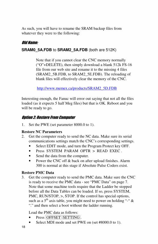
As such, you will have to rename the SRAM backup files from
whatever they were to the following:
Old Name:
SRAM0_5A.FDB to SRAM2_5A.FDB (both are 512K)
Note that if you cannot clear the CNC memory normally
(“O”+DELETE), then simply download a blank 512k FS-16
file from our web site and rename it to the missing 4 files
(SRAM2_5B.FDB, to SRAM2_5E.FDB). The reloading of
blank files will effectively clear the memory of the CNC.
http://www.memex.ca/products/SRAM2_5D.FDB
Interesting enough, the Fanuc will error out saying that not all the files
loaded (as it expects 5 half Meg files) but that is OK. Reboot and you
will be ready to go.
Option 2: Restore From Computer 1. Set the PWE (set parameter 8000.0 to 1).
Restore NC Parameters
2. Get the computer ready to send the NC data. Make sure its serial
communications settings match the CNC’s corresponding settings.
• Select EDIT mode, and turn the Program Protect key OFF.
• Press SYSTEM PARAM OPTR > READ EXEC .
• Send the data from the computer.
• Power the CNC off & back on after upload finishes. Alarm
300 is normal at this stage if Absolute Pulse Coders exist.
Restore PMC Data
3. Get the computer ready to send the PMC data. Make sure the CNC
is ready to receive the PMC data - see “PMC Data” on page 7.
Note that some machine tools require that the Ladder be stopped
before all the Data Tables can be loaded. If so, press SYSTEM,
PMC, RUN/STOP, >, STOP. If the control has special options,
such as a 5th
axis table, you might need to power on holding “-“ &
“.” and then select a boot without the ladder running.
Load the PMC data as follows:
• Press OFFSET SETTING .
• Select MDI mode and set PWE on (set #8000.0 to 1).
19
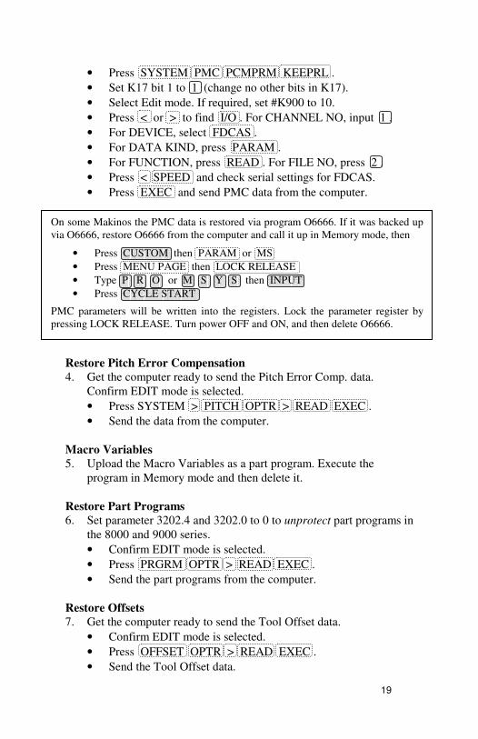
On some Makinos the PMC data is restored via program O6666. If it was backed up
via O6666, restore O6666 from the computer and call it up in Memory mode, then
• Press CUSTOM then PARAM or MS
• Press MENU PAGE then LOCK RELEASE
• Type P R O or M S Y S then INPUT
• Press CYCLE START
PMC parameters will be written into the registers. Lock the parameter register by
pressing LOCK RELEASE. Turn power OFF and ON, and then delete O6666.
• Press SYSTEM PMC PCMPRM KEEPRL .
• Set K17 bit 1 to 1 (change no other bits in K17).
• Select Edit mode. If required, set #K900 to 10.
• Press < or > to find I/O . For CHANNEL NO, input 1 .
• For DEVICE, select FDCAS .
• For DATA KIND, press PARAM .
• For FUNCTION, press READ . For FILE NO, press 2 .
• Press < SPEED and check serial settings for FDCAS.
• Press EXEC and send PMC data from the computer.
Restore Pitch Error Compensation
4. Get the computer ready to send the Pitch Error Comp. data.
Confirm EDIT mode is selected.
• Press SYSTEM > PITCH OPTR > READ EXEC .
• Send the data from the computer.
Macro Variables
5. Upload the Macro Variables as a part program. Execute the
program in Memory mode and then delete it.
Restore Part Programs
6. Set parameter 3202.4 and 3202.0 to 0 to unprotect part programs in
the 8000 and 9000 series.
• Confirm EDIT mode is selected.
• Press PRGRM OPTR > READ EXEC .
• Send the part programs from the computer.
Restore Offsets
7. Get the computer ready to send the Tool Offset data.
• Confirm EDIT mode is selected.
• Press OFFSET OPTR > READ EXEC .
• Send the Tool Offset data.
20
Get the computer ready to send the Work Offset data.
• Press WORK OPTR > READ EXEC .
• Send the Work Offset data.
8. Reload CAP data and Graphics & Animation data if present.
• In Edit mode, press OFFSET CAP TL > READ .
9. Reset Absolute Pulse Encoders, if necessary.
• Power on holding P & CAN
• Manually home the machine.
• If Alarm 300 persists, then:
Select MDI mode and set PWE on (set #8000.0 to 1).
Press SYSTEM PARAM . Set #P1815.4 to 1 on all axes.
Reset PWE (#8000.0 to 0) and power the control off & on.
Manually home the machine again. Set PWE.
Press SYSTEM PARAM . Set #P1815.4 to 1 on all axes.
For Relative Position, set #P3104.3 to 1.
Reset PWE. Press RESET .
21
Verify The Control
Once the upgrade is completed, including the reloading of all
parameters, test the machine via the following procedure.
IMPORTANT: Do not move the machine until you are sure
all parameters have been restored.
• Change to either MDI mode or Program mode.
• Home all axes, tool changers and pallets.
• Check spindle functionality through all speeds and gear ranges.
• Check Clockwise and Counter-clockwise spindle rotation with M3
and M4 commands.
• Check the tool changer. Be sure that the tool received was the tool
requested and that the carousel rotates in the proper direction.
• Check the pallet changer (if applicable). If the machine requires
special custom macros for a pallet changer or tool changer, be sure
that they are present.
Note: At the end of this process, we recommend that one final SRAM backup
be made using the PCMCIA SRAM card in IPL mode. By this point the
machine is working with the new memory (2 Megs).
22
Installation Checklist
• Check machine - Power ON and check for problems before
you start.
• Read Addendum.
• Backup settings, options, parameters and programs.
• Power OFF.
• Depress EMERGENCY STOP.
• Change SIMMs.
• Power On the Control holding O & DELETE to clear all.
• Set PWE to enable.
• Restore settings.
• Restore parameters & part programs.
• Change memory size option.
• Reload Macro Programs O8000 and O9000 series.
• Check the parameters and machine operation thoroughly.
Complete.
23
Fanuc 16 Technical Summary
Punching NC Parameters EDIT mode; SYSTEM PARAM
OPTR > PUNCH EXEC
Pitch Error Compensation EDIT mode; SYSTEM > PITCH
OPTR > PUNCH EXEC
Macro Variables EDIT mode; OFFSET > MACRO
OPTR > PUNCH EXEC
All Programs EDIT mode; PRGRM >
O – 9 9 9 9 PUNCH EXEC
Offsets EDIT mode; OFFSET (or WORK )
OPTR > PUNCH EXEC
Reading NC Parameters EDIT mode, Protect key off; SYSTEM
PARAM OPTR > READ EXEC
Pitch Error Compensation EDIT mode; SYSTEM > PITCH
OPTR > READ EXEC
All Programs EDIT mode; #3202.4 & .0 = 0; PRGRM
OPTR > READ EXEC
Offsets EDIT mode; OFFSET (or WORK ),
OPTR > READ EXEC
Initializing Erase Entire Memory Power On holding O & RESET
with Write Protect Key off
Typical Serial Communications Parameter Settings NOTE: For Channel 3, see Parameter Manual, Fanuc #62450E, section 4.2 (5).
Parameter Description Setting
0020 I/O Channel 0 or 1 = Chan. 1, 2=2 0100.1 Tape Vertical Check – all channels 0 = No TV Check 0100.3 EOB format in ISO code – all chan. 1 = CR, LF, LF (0 = LF) 0100.5 DNC Handshake method – all chan. 1 = DC3 when buffer full 0100.7 Treatment of Null code – all chan. 1 = Ignore Nulls (0 = alarm) 0101.0 Stop Bits – Channel 0 0 = 1, 1 = 2 stop bits 0101.3 ISO or ASCII Input code – Chan. 0 0 = Auto-select (1 = ASCII) 0101.7 Feed output – Channel 0 1 = no feed (0 = feed output) 0102 Device Type – Channel 0 0 = RS232C with DC codes 0103 Baud Rate – Channel 0 10=4800,11=9600,12=19200
0111-0113 Same as 0101-0103 but for I/O Channel 1
0121-0123 Same as 0101-0103 but for I/O Channel 2
24
Applicable CPU Boards
16-B
A16B-3200-0010
Available Memory SIMM
16-B (0010 CPU) FROM SRAM
A20B-2902-0080 4 Meg 512 kB
A20B-2902-0081 4 Meg 0
A20B-2902-0082 2 Meg 0
A20B-2902-0090 8 Meg 2 Meg
A20B-2902-0091 8 Meg 0
A20B-2902-0092 6 Meg 0
A20B-2902-0093 8 Meg 512 kB
A20B-2902-0094 6 Meg 512 kB
Standard Fanuc Serial Port: (DB-25 Female)
1 = Frame Ground 6 = Data Set Ready
2 = Transmit Data 7 = Signal Ground
3 = Receive Data 8 = Carrier Detect
4 = Ready To Send 20 = Data Terminal Ready
5 = Clear To Send 25 = +24 Volts DC
Standard Fanuc Serial Cable:
Computer Fanuc
25-pin Female to 25-pin Male
Tx – 2 - 3 – Rx Rx – 3 - 2 – Tx
RTS – 4 - 5 – CTS CTS – 5 - 4 – RTS SG – 7 - 7 – SG (Ground)
6+8+20 Jumpered
9-pin Female to 25-pin Male
Tx – 3 - 3 – Rx Rx – 2 - 2 – Tx
RTS – 7 - 5 – CTS CTS – 8 - 4 – RTS SG – 5 - 7 – SG (Ground)
- 6+8+20 Jumpered
25
Fanuc Protocol: E,7,x
The standard serial communications protocol for Fanuc controls is
always Even Parity and 7 Data Bits. Stop Bits are either 1 or 2, as set
via parameter 101, 111 or 121, depending on the channel used. (see
“Typical Serial Communications Parameter Settings” on page 16).
NOTE: SRAM PC Card File Naming Conventions
The files saved on the SRAM PC card during backup are named
according to a set of naming schemes, depending upon memory module
size. When performing a restore operation after a memory upgrade,
files backed up from a different memory size will be ignored, since the
directory looks for filenames according to the scheme for the current
memory size. Therefore the backup files must be renamed to match the
naming scheme of the new memory size. A computer with PC card
reading capability is required to access and rename the files on the card.
The naming schemes for each memory size are as follows:
Memory PC Card Backup File Naming Scheme
512K SRAM0_5A.FDB 1.0MEG SRAM1_0A.FDB, SRAM1_0B.FDB 1.5MEG SRAM1_5A.FDB, SRAM1_5B.FDB, SRAM1_5C.FDB 2.0MEG SRAM2_5A.FDB, SRAM2_5B.FDB,
SRAM2_5C.FDB, SRAM2_5D.FDB, SRAM2_5E.FDB
Example:
When upgrading from 1280 Meters (512k) to 5120 Meters (2 Megs),
the files on the card would be renamed from “SRAM0_5A.FDB” to
“SRAM2_5A.FDB”. The 4 remaining files in the 2 Meg naming
scheme will be created by the control, after you abort the load after the
first file.
26
Memex Technical Support & Service
In case of technical difficulty with the memory upgrade procedure,
please contact your Memex dealer, or call Memex Automation
Technical Support at 1-905-635-3041.
Appendix A of this manual may be used to record technical
information, service advice, etc. as needed.
If you have any other questions or concerns, need answers to technical
questions, or need information about Memex products and/or services,
please contact your local Memex dealer, or contact Memex Automation
at:
Memex Automation Inc. 200 – 3425 Harvester Rd.,
Burlington, Ontario Canada L7N 3N1 Phone: 1-905-635-3040 Fax: 1-905-631-9640
www.memex.ca
[email protected]
[email protected]
27
Fanuc 16MB with PCMCIA SRAM in the MEM card slot on the
A16B-3200-0010 CPU card.
28 Appendix A: Parameter Records N
C S
erv
ice
Pa
ram
eter
s
Par
.#
990
0
992
0
992
2
992
3
99
21
99
24
Val
ue
Par
.#
992
5
992
6
992
8
992
9
992
7
993
0
Val
ue
Par
.#V
alu
eP
ar.#
Val
ue
Par
.#V
alu
e
Ser
ial
Co
mm
un
ica
tio
ns
Pa
ram
eter
sN
ote
: G
rey a
rea
(#
13
1-1
32
) a
re f
or
Ch
an
ne
l 3
, n
orm
ally
use
d f
or
RS
-42
2 lin
k.
Par
.#V
alu
e
20
10
0
Par
.#V
alu
e
13
1
13
21
33
Par
.#V
alu
e
12
1
12
21
23
Par
.#V
alu
e
11
1
11
21
13
Par
.#V
alu
e
10
1
10
21
03
Chan
nel
1
Chan
nel
0
Ch
ann
el 2
Ch
ann
el 3
All
Chan
nel
s
Fan
uc
Sy
stem
16
/18
Mac
hin
e P
aram
eter
Wo
rksh
eet
Fan
uc
So
ftw
are
Ver
sio
n:
__
__
__
__
__
__
___
Mai
n C
PU
Bo
ard N
o.:
__
__
___
__
__
___
__
__
__
__
__
___
__
__
___
_
Com
pan
y:_
__
__
___
__
__
___
__
__
___
__
__
___
__
_M
ach
ine
No
.:_
___
__
__
__
__
__
__
Dat
e:_
__
__
___
__
__
__
__
_
Set
tin
g D
ata
Scr
een
Par
amet
er W
rite
Ty
pe
Fo
rmat
TV
Chec
kS
equ
ence
Sto
p (
Pro
gra
m N
o.)
Pu
nch
Co
de
Seq
uen
ce S
top
(S
equ
ence
No
.)
Inp
ut
Un
itX
Ax
is M
irro
r
I/O
Ch
annel
Y A
xis
Mir
ror
Seq
uen
ce N
o.
29
PC
Pa
ram
eter
s
1 2 3 4 5 6 7 8 9
10
11
13
14
15
16
17
18
19
20
12
21
22
23
24
25
26
27
28
29
30
31
33
34
35
36
37
38
39
40
32
Dat
aN
o.
Dat
aN
o.
No
.D
ata
No
.P
rese
t
Tim
ers
Co
unte
rsK
eep
Rel
ays
Cu
rren
tN
o.
Dat
a
Sp
are
1 2 3 4 5 6 7 8 9
10
11
13
14
15
16
17
18
19
20
12
1 2 3 4 5 6 7 8 9
10
11
13
14
15
16
17
18
12
30
Da
ta T
ab
les
1 2 3 4 5 6 7 8 9
10
11
13
14
12
No
. 0
No.
of
Dat
aP
aram
eter
Off
set
Sp
ecia
lT
able
No.
0
"No
. o
f D
ata
" ro
w 0
in
dic
ate
s h
ow
ma
ny d
ata
ta
ble
s t
he
re a
re.
Th
e r
em
ain
ing
ro
ws in
tha
t co
lum
n in
dic
ate
ho
w m
an
y e
ntr
ies a
re in
ea
ch
ta
ble
. P
ag
e d
ow
n t
hro
ug
h e
ach
tab
le a
nd
re
co
rd a
ll t
he
da
ta i
n e
ac
h,
us
ing
th
e f
orm
on
th
e n
ex
t tw
o p
ag
es
-
ph
oto
copy t
he
form
befo
re s
tart
ing
, if m
ore
are
ne
ede
d.
31
1 2 3 4 5 6 7 8 9
No
. 0
Dat
a
0 1 2 3 4 5 6 7 8 9 0 1 2 3 4
1 2 3 4 5 6 7 8 9
No
. 0
Dat
a
0 1 2 3 4 5 6 7 8 9 0 1 2 3 4
1 2 3 4 5 6 7 8 9
No
. 0
Dat
a
0 1 2 3 4 5 6 7 8 9 0 1 2 3 4
1 2 3 4 5 6 7 8 9
No
. 0
Dat
a
0 1 2 3 4 5 6 7 8 9 0 1 2 3 4
32
5 6 7 8 9 0 1 2 3 4 5 6 7 8 9 0 1 2 3 4 5 6 7 8 9 0
5 6 7 8 9 0 1 2 3 4 5 6 7 8 9 0 1 2 3 4 5 6 7 8 9 0
5 6 7 8 9 0 1 2 3 4 5 6 7 8 9 0 1 2 3 4 5 6 7 8 9 0
5 6 7 8 9 0 1 2 3 4 5 6 7 8 9 0 1 2 3 4 5 6 7 8 9 0
35
Memex Automation Inc.
200 – 3425 Harvester Rd., Burlington, Ontario Canada L7N 3N1
Phone: 1-905-635-3040 Fax: 1-905-631-9640
www.memex.ca
Sales: (905) 635-3043
Support: (905) 635-3041
Thank you for choosing Memex Memory
File: \ISO9000\DOCs\ M100744A - Memex FROM Upgrade for Fanuc 16B [0010].doc