Technical Summary for Fanuc 10 .................................................... 17-19 Parameter Worksheet ....................................................................... 20-22 Initialization of Sub-Memory for GN10TF ……………………………….. 23
Chapter 2 – The Basics
M100703B
Page 3
Introduction
General
BEFORE STARTING ANYTHING, PLEASE BACK-UP YOUR PARAMETERS
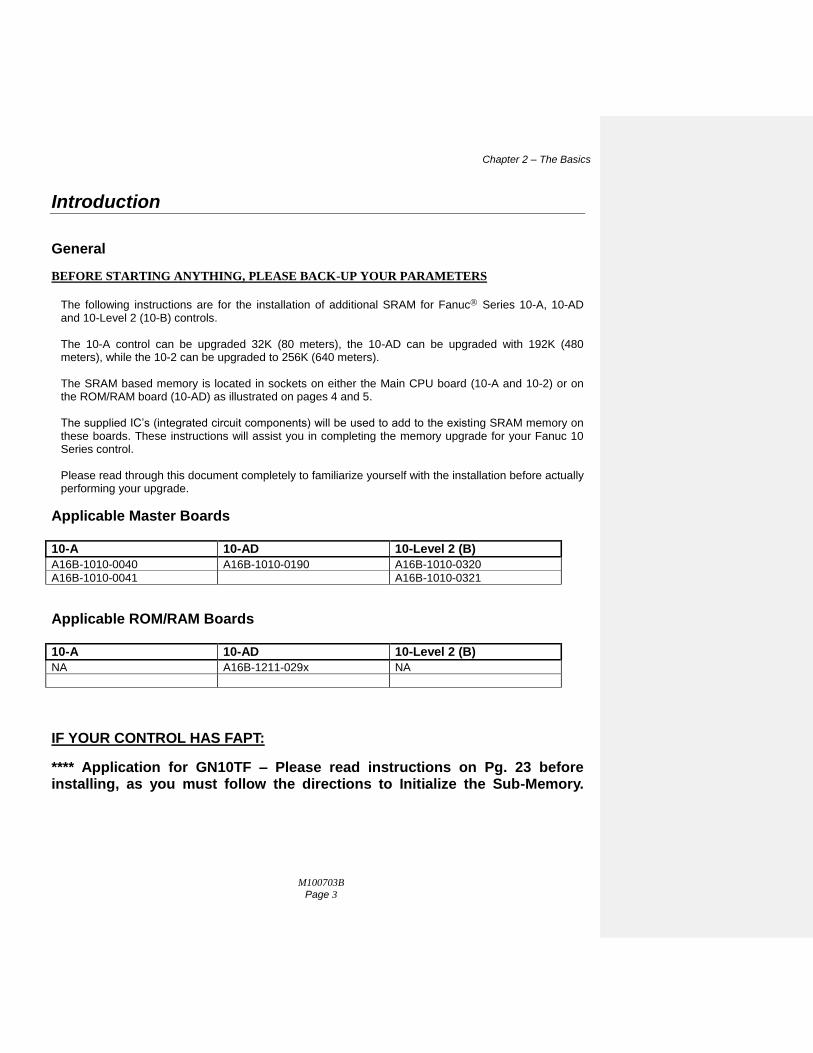
The following instructions are for the installation of additional SRAM for Fanuc Series 10-A, 10-AD and 10-Level 2 (10-B) controls. The 10-A control can be upgraded 32K (80 meters), the 10-AD can be upgraded with 192K (480 meters), while the 10-2 can be upgraded to 256K (640 meters). The SRAM based memory is located in sockets on either the Main CPU board (10-A and 10-2) or on the ROM/RAM board (10-AD) as illustrated on pages 4 and 5. The supplied IC’s (integrated circuit components) will be used to add to the existing SRAM memory on these boards. These instructions will assist you in completing the memory upgrade for your Fanuc 10 Series control. Please read through this document completely to familiarize yourself with the installation before actually performing your upgrade.
Applicable Master Boards
10-A 10-AD 10-Level 2 (B)
A16B-1010-0040 A16B-1010-0190 A16B-1010-0320
A16B-1010-0041 A16B-1010-0321
Applicable ROM/RAM Boards
10-A 10-AD 10-Level 2 (B)
NA A16B-1211-029x NA
IF YOUR CONTROL HAS FAPT:
**** Application for GN10TF – Please read instructions on Pg. 23 before installing, as you must follow the directions to Initialize the Sub-Memory.
Chapter 2 – The Basics
M100703B
Page 4
Locating SRAM Modules (10-A and 10-2)
CAC CAZ CAG CAE CAL CAS CAH
CAP
CF1 CF2 CF3 CF4
CV1 CV2 CV3 CA1
CA5 CA4 CA3 CD1
Memory
Modules
A16B-1010-0040
A16B-1010-0041
CAC CAZ CAG CAE CAL CAS CAH
CAM CAI
CA6
CAP
CV21
CF91
CV22
CF92
CA1
CA2
CFE
Memory Modules
A16B-1010-0320
A16B-1010-0321
Chapter 2 – The Basics
M100703B
Page 5
Locating ROM/RAM Board (10-AD) The SRAM modules for the 10-AD upgrade are to be inserted in the sockets located on the ROM/RAM board A16B-1211-029x (as shown below). Locate this board in your machine control cabinet. It can be found connected to the master board connector labeled CAB.
Locating SRAM Modules (10-AD)
CA6
CBA
A16B-1211-029x
Memory
Modules
Chapter 2 – The Basics
M100703B
Page 6
The Basics
Installation Considerations The installation of the SRAM modules should be conducted with care. Never install or remove a board with the control power on (the main power can be on, but not the control). Take care with the handling of the integrated circuits, as they are static sensitive. Do not place the IC’s in any other sockets than as per pages 4 and 5. Do not force, drop or otherwise mishandle the modules during the installation procedure and always check the functionality of the machine at the end of the installation (i.e. move the axes, perform a tool change, run a program, etc.).
Backup Critical Parameters For series 10-A, 10-AD and 10-2(B) upgrades it is very important that you have a hard copy back-up of all your control’s critical parameters. The following instructions will assist you in dumping a majority of the Fanuc’s parameters to a PC to be saved. However, it is still advised to keep or make, if you haven’t already, a written copy of ALL the critical parameters. You can use the Parameter Sheets in the Appendix of this manual to write NC (Service) Parameters: 0, 3, 20-23, 5001-5122, 9000 and 9100 to the end. Be sure that all of the files you download have been successfully recorded and saved on your computer before performing the upgrade to your control. Otherwise you will have no choice but to enter ALL parameters by hand in MDI mode.
Verify Your Control Once the memory modules have been installed and all parameters have been restored, satisfy yourself that the control is working properly. Test the machine by the following procedure through either MDI or program:
Home all axes, tool-changers and pallets.
Check spindle functionality through all speeds and gear ranges.
Check also Clockwise and Counter-clockwise rotation with M3 and M4 commands.
Check the tool changer. Be sure that the tool you received was the tool requested and that the carousel rotates in the proper direction.
Check the pallet changer (if applicable). If your machine requires special custom macros for a pallet changer or tool changer, be sure that they have been loaded.
Once your machine has been proven, you have successfully upgraded your control.
Chapter 3 – Installation for Fanuc 10
M100703B
Page 7
Installation for Fanuc 10
Backup Your Control
Before starting the installation, power on the control and verify that the machine tool is in good working order.
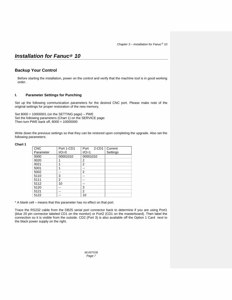
I. Parameter Settings for Punching Set up the following communication parameters for the desired CNC port. Please make note of the original settings for proper restoration of the new memory.
Set 8000 = 10000001 (on the SETTING page) – PWE Set the following parameters (Chart 1) on the SERVICE page: Then turn PWE back off, 8000 = 10000000 Write down the previous settings so that they can be restored upon completing the upgrade. Also set the following parameters: Chart 1
CNC Parameter
Port 1-CD1 I/O=0
Port 2-CD1 I/O=1
Current Settings
0000 00001010 00001010
0020 1 2 0021 1 2
5001 1 -- 5002 -- 2
5110 3 -- 5111 2 --
5112 10 -- 5120 -- 3
5121 -- 2 5122 -- 10
* A blank cell – means that this parameter has no effect on that port. Trace the RS232 cable from the DB25 serial port connector back to determine if you are using Port1 (blue 20 pin connector labeled CD1 on the monitor) or Port2 (CD1 on the masterboard). Then label the connection so it is visible from the outside. CD2 (Port 3) is also available off the Option 1 Card next to the black power supply on the right.
Chapter 3 – Installation for Fanuc 10
M100703B
Page 8
II. PUNCHING CNC NC PARAMETERS (CNC - PC)
Connect the Fanuc serial cable between the serial ports on your computer and the CNC.
Set up your computer with a terminal software program (Telix / ProCom+ / Hyper Terminal).
Perform the following steps on the PC and CNC as follows: PC-- Using 4800, Even parity, 7 Data bits and 2 Stop bits,
set your terminal program to receive a file. PC-- Enter a file name to record the NC parameters. ie; #103.NCP (103 being the machine #) CNC-- Go into EDIT mode. CNC-- Make sure the “Memory Protect” key is off. CNC-- Press the < soft key, SERVICE, CHAPTER, PARAMETER, > , PUNCH, ALL keys. (The CNC will flash PNCH on the lower portion of the CRT) (The PC will display the text and count lines until finished) PC-- Save the file you just received from the CNC on the computer.
IMPORTANT: Check the .NCP file with a text editor to visually confirm that system parameters
N0900 - have been sent to the computer. If these parameters are not found in your listing, please repeat this section (Punching CNC Parameters). Take this moment to write down the 900 level system parameters for backup purposes.
III. PUNCHING PMC PARAMETERS (CNC PC) Caution: This step is not always available on Fanuc Series 10 Controls. If it is not possible, be sure to write down all the PC parameter data on the parameter sheets provided.
Set up the computer in accordance with section II.
Perform the following steps on the PC and CNC as follows: PC-- Set your communication program to receive your CNC parameter file. Enter a filename to record the PMC parameters. CNC-- In Edit mode press the < , SERVICE, CHAPTER, PARAMETER, > , PUNCH, PMC keys. PC-- Save the file you just received from the CNC on the computer.
IV. PUNCHING TOOL OFFSET DATA (CNC PC)
Set up the computer in accordance with section II.
Perform the following steps on the PC and CNC as follows:
Comment [WLB1]:
Chapter 3 – Installation for Fanuc 10
M100703B
Page 9
PC-- Set your communication program to receive a part-program file. Enter a filename to record your Tool Offset data. CNC-- Still in Edit Mode press the < , OFFSET, CHAPTER, PUNCH, ALL, EXEC keys. PC-- Save the file you just received from the CNC.
V. PUNCHING CNC PART PROGRAMS (CNC PC) Before backing up the Part Programs, check to see if there are any programs listed in the 8000’s or 9000’s. If there are, make sure the Program Protect Parameter, NC parameter 2201--bit 0, must be a 0 for the 9000 series part-programs and parameter 11--bit 0 must be a 0 for the 8000 series programs. This will allow ALL part-programs and macros to be punched properly.
Set up the computer in accordance with section II.
Perform the following steps on the PC and CNC as follows: PC-- Set your communication program to receive a part-program file. Enter a filename to record your CNC part programs. CNC-- In Edit mode press the < , PROGRAM, CHAPTER, TEXT, > , > , PUNCH, ALL, EXEC keys. PC-- Save the file you just received from the CNC. Note: Check that you have received All of your part program files especially those program macros
listed as O8XXX or O9XXX. Programs listed in the 8000 or 9000 number range can be protected by NC parameters 2201.0 and 11.4, preventing those programs from being punched out.
VI. CHECK YOUR WORK.
Check that you have received all of the information out of your CNC control. Check also that any Custom Macro Variables (500-999) and Setting Screen data have been recorded.
Chapter 3 – Installation for Fanuc 10
M100703B
Page 10
Installation Procedures for Fanuc 10 Make a print-out of your .NCP parameter file. When you are confident that you have completely saved all of your CNC information, you will be ready to proceed with your memory upgrade. The part program and system memory is located on the Master Board for Fanuc 10-A and 10-2(B) Series controls and on the ROM/RAM board for the 10-AD (see pages 4-5). Locate this board in your machine control cabinet.
Check that you have received all of the information out of your CNC control. Check also that any Custom Macro Variables have been written down and recorded.
1. Power OFF the control and the machine. Open the cabinet door to expose the control’s Master Board.
2. Clearly label all of the cables, daughter boards and their locations that are connected to the Master Board. Once all the cables and boards are labeled, you can loosen and remove the cables and daughter boards using a screwdriver including the ROM/RAM board (for 10-AD upgrades). You are now ready to remove the battery connection (CPA7) from the bottom of the Master Board.
3. Put on the anti-static wrist strap and clip the other end of it to the GND post in the top corner of the Master Board. Locate the SRAM socket positions on the Master Board / ROM/RAM board (see pages 4-5). This is where you have to insert or replace the larger of the new memory modules. Optionally if there are already modules in these locations, you can use the small screwdriver or a chip puller to carefully remove them. Also locate the smaller SRAM parity socket positions on the board. This is where the smaller of the new memory modules go.
4. One by one, remove the memory modules from the kit. Note that the components are static sensitive and try not to bend any pins.
5. Orient the module above the socket with the “notch” in the same direction as the “notch” in the
socket (Pointing “Down”). Place one row of pins in the socket, then with a little sideways pressure put the second row in. With steady pressure, push the memory module down into the socket. Check that none of the pins have bent in during this process. Repeat this step for the remaining modules.
6. Again, check your work before replacing any daughter boards back in the control. After you replace the daughter boards and restore all of the cable connections, check your work.
Chapter 3 – Installation for Fanuc 10
M100703B
Page 11
Fanuc 10-TFA Masterboard
Chapter 3 – Installation for Fanuc 10
M100703B
Page 12
Restoring your Fanuc 10 Option Check Note:
If you have a Fanuc 10A (A16B-1010-0040), you should check your NC parameters to make sure that Parameter 9110 bit 3 = 0 (we call this P9110.3) and P9110.4 = 1 to get (80M) and it looks like P9110 = xxx10xxx (where “x” is original value).
If you have a Fanuc 10B (A16B-1010-0190), you will need to have P9110.3=0 + P9110.4=0 + P9120.2=0 + P9120.3=0 + P9120.4=1 (480M).
If you have a Fanuc 10B Level II (A16B-1010-0320) you need to have P9110.3=0 + P9110.4=0 + P9120.2=0 + P9120.3=0 + P9120.4=0 + P9120.5=1 (640m).
I. INITIALIZING THE MEMORY 1. With the “7” and “9” keys depressed on the front MDI panel, power on the control. This action will
cause the control to start-up and immediately clear the entire memory. If the control will not
power on at this point, check that the cabinet door interlock is bypassed. When the control powers on, it will eventually show the I.P.L. Screen.
2. At the prompt, you will enter “99” then “INPUT”. Use the Input button to the right of the MDI keypad.
3. Enter “Y” to Initialize the system label.
4. Enter the number you wrote down from parameter 9000 on the parameter sheet, for the No. of Axes.
5. Beginning with parameter 9100, enter the hexi-decimal value of each parameter for the Option #’s that need to be entered (ie; 9100 = 1010 0011 or A3 hex). If you incorrectly enter a number at this point, you will have to go back to step 6. and begin the process again.
6. When you reach the end, answer “Y” to clear the files. When you get back to the I.P.L. menu, Press “6” to End I.P.L.
7. Locate the Parameter Write Enable (PWE) parameter, 8000, in the Settings (Service) screen. Change the parameter to a 1 to enable the PWE.
8. Go to the Parameter (Setting) screen by pressing the SERVICE soft-key and start re-entering the NC-Service Parameters that you wrote down on the parameter sheet. Enter all the serial parameters from 0 to 5152 inclusive.
9. Now serially reload the remaining parameters or if need be, re-enter the remaining parameters by hand from your parameter tape/list/backup.
Chapter 3 – Installation for Fanuc 10
M100703B
Page 13
II READING THE CNC PARAMETERS (PC CNC) Connect the cable to the computer and the serial port on the CNC.
Set up the computer as per before.
Restore the CNC communication parameters (page 7).
Perform the following steps on the PC and CNC as follows: PC-- Load your communications software. CNC-- Go into EDIT mode. CNC-- Press ESTOP. CNC-- Press the < , SERVICE, CHAPTER, PARAMETER, > , READ, ALL keys. PC-- Start sending the file that contains your Memex modified CNC NC parameters from your PC.
Remember to send your files using ASCII data, Even Parity, 7 Data bits, and 2 Stop bits. CNC-- Once the parameters have been loaded, power the machine off, then on to have these
parameters take effect.
III READING THE PMC PARAMETERS (PC CNC) *Caution: If your Fanuc 10 Control can’t Punch or Read the PMC parameters, at this point you must re-enter them by hand. Once the NC parameters are reloaded, power off the control, then power it on again. Turn on the PWE parameter again (parameter 8000), then press the NC/PC button and reload all of the PC parameters. When you are confident that all of the parameters are entered and correct. Turn off the power.
Connect the cable to the computer and the serial port on the CNC.
Set up the computer in accordance with section II.
Restore the CNC communication parameters in accordance with section I.
Perform the following steps on the PC and CNC as follows: PC-- Load your communications software. CNC-- Go into EDIT mode. CNC-- Press ESTOP. CNC-- Press the < , SERVICE, CHAPTER, PARAMETER, > , READ, PMC keys. PC-- Start sending the file that contains your modified CNC NC parameters from your PC. Remember to send your files using ASCII data, Even Parity, 7 Data bits, and 2 Stop bits. CNC-- Once the parameters have been loaded, power the machine off, then on to have these parameters take effect.
Chapter 3 – Installation for Fanuc 10
M100703B
Page 14
IV. READING THE CNC PART PROGRAMS (PC--> CNC)
Connect the cable to the computer and the serial port on the CNC.
Set up the computer in accordance with section II.
It is necessary that no alarms remain at this point so make sure parameter 8000 on the Settings page (PWE) is off.
Perform the following steps on the PC and CNC as follows: PC-- Load your communications software. CNC-- In Edit mode press the < , PROGRAM, CHAPTER, TEXT, > , > ,READ, ALL keys. (The CNC will flash READ in the lower portion of the CRT.) (The PC will display the text and count lines until finished). PC-- Start sending the file that contains your CNC part programs from your PC. Remember to send your files using ASCII data, Even Parity, 7 Data bits, and 2 Stop bits.
V. RESTORING YOUR TOOL OFFSETS 1. Load a single part program using the above procedure to load the Tool Offset file you received
from your control. The Offsets will load as an executable part program file into the CNC. Press Cycle Start to run this file and reload your Offsets.
2. Restore any of the NC parameters that you changed from their original state. You will have to set PWE to do this. Also check that the Settings Page is back to its original state. This will complete your installation.
3. Remember to change the batteries on your control on a regular basis (every year) with the CNC control power ON.
Chapter 3 – Installation for Fanuc 10
M100703B
Page 15
VI. TEST THE CONTROL Power on the control and release the Emergency Stop. The control should start-up normally with the new memory in the control. Check the functionality of the machine at this point: Re-Home the machine axes, test the spindle, test the tool changing mechanism (be sure you get the tool you request and that it goes into the correct pocket), check out any pallet changers and other peripherals. Caution: Keep your rapid and feed rate overrides low. The machine may not behave the way you might
expect. If abnormalities in the operation are noticed, recheck all of the NC and PC system parameters that you have restored. Absolute Encoder Reset: If you have absolute encoders you may have over-travel alarms at this point when you don’t expect it. The normal method to clear these is to power on in IPL (holding “-“+”.”). Select 4 for SETTING, then key “N” for no check of “SOFT OT AT POWER ON”. Hit INPUT and then 6 INPUT to end IPL. It should boot normally – proceed to home the machine manually.
Fanuc 10A – all upgraded (no empty sockets)
Chapter 3 – Installation for Fanuc 10
M100703B
Page 16
INSTALLATION CHECKLIST
Check Machine - Power On - Check for Machine Problems Before You Start.
Backup Parameters. Depress E-STOP
Power Off.
Remove battery connection.
Insert memory modules.
Power On the Control with “7” + “9” depressed to initialize new memory.
Enter “99” in I.P.L. Menu.
Enter the Number of axes and all of the Option data.
Press “6” to “End IPL”.
Set PWE, then Restore the base Service Parameters.
Reload the remaining NC Parameters.
Power Off, then On.
Set PWE, then reload the PC Parameters.
Power Off, then On.
Clear all alarms (PWE, E-STOP etc.)
Reload part programs and tool offsets.
Check Parameters and Machine Operation Thoroughly. Done...
Chapter 4 – Appendix
M100703B
Page 17
Appendix
Technical Summary for Fanuc 10 PUNCHING: Punch NC Parameters - EDIT mode, SERVICE screen, key PUNCH - ALL Punch Pitch Error Comp. - EDIT mode, SERVICE screen, key PUNCH - PITCH Punch All Programs - EDIT mode, PRGRM screen, key PUNCH - ALL READING: Load NC Parameters - EDIT, E-Stop, PWE, SERVICE screen, key READ - ALL Load Pitch Error Comp. - EDIT, E-Stop, PWE, SERVICE screen, key READ - PITCH Load All Programs - EDIT mode, PRGRM screen, key READ - ALL CLEARING: Directory and Programs - EDIT mode, PRGRM screen, key DELETE-PROGRAM-ALL Delete Entire BMU - Power On holding “7”+”9” Parameter Function Description 0.2 1=Without 0=With Parity Bit 0.3 1=LF 0=LF,CR,CR End of line on punch 0.4 1=EIA 0=ISO Punch Code Format (choose ISO) See parameters 5111 and 5112 for STOP BITS and BAUD RATE information. 20 Input device interface number for foreground 0: Tape Reader 1: RS-232-C interface 1 2: RS-232-C interface 2 3: RS-232-C interface 3 10: Remote (DNC) 11: 20mA current type interface (ASR33, ASR44) 13: RS-422 interface 21 Output device interface number for foreground (Same as 20 except no Tape Reader option) 22 Input device interface number for background (Same as 20) 23 Output device interface number for background (Same as 20 except no Tape Reader option) 5001 I/O device No. to be connected to RS232C interface 1 5002 I/O device No. to be connected to RS232C interface 2 5003 I/O device No. to be connected to RS232C interface 3 5011 I/O device No. to be connected to ASR33/44 interface 5013 I/O device No. to be connected to RS422 interface
Chapter 4 – Appendix
M100703B
Page 18
5110 Specifications number of I/O device corresponding to device number 1 1: Control codes (DC1 - DC4) are used and feed is punched 2: Control codes (DC1 - DC4) are not used and feed is punched 3: Control codes (DC1 - DC4) are used and feed is not punched (preferred) 4: Control codes (DC1 - DC4) are not used and feed is not punched 5: Reserved 6: PPR 7: FANUC cassette 5111 Number of stop bits of I/O device corresponding to device number 1 1: 1 Stop bit 2: 2 Stop bits 5112 Baud rate of I/O device corresponding with device number 1 1: 50 7: 600 2: 100 8: 1200 3: 110 9: 2400 4: 150 10: 4800 5: 200 11: 9600 2201.0 Programs O9000 - O9999 (canned cycles) can 0: Be edited 1: Not be edited 11.0 Programs O8000 - O8888 can 0: Be edited 1: Not be edited 2200.3 When programs are loaded, M02, M30 and M99 should 0: Be assumed as program end 1: Not be assumed as program end. In this case a program number must exist in the first block of
the program. 2200.6 When punching the program with external I/O device control (foreground editing only)
[parameter 20 and 21], 0: Punch a single program 1: Punch all programs STANDARD FANUC SERIAL PORT: (DB-25 Female) 1 = Frame Ground 6 = Data Set Ready 2 = Transmit Data 7 = Signal Ground 3 = Receive Data 8 = Carrier Detect 4 = Ready To Send 20= Data Terminal Ready 5 = Clear To Send 25= +24 Volts DC
Chapter 4 – Appendix
M100703B
Page 19
Fanuc 10 CNC controls have memory modules in sockets on the Masterboard. With Fanuc the notches are pointing down and if installed carefully with the power off (and not touching any other chips) one can not lose the parameters. That said, always plan to have to reload all parameters and thus perform a full system backup beforehand. Note that Memex also makes Fanuc 10 rechargeable lithium battery replacement units – check our MxBRU on www.memex.ca
The remainder of the Data Tables can be written down on the following chart. Photocopy the chart as many times as you need to record the rest of the Data. Line 0 of the No. of Data column in the previous chart, will tell you how many tables there are. The remaining lines in the No. of Data column will tell you how many entries are in each table. Page Down through each table, to record all the data on each.
Chapter 4 – Appendix
M100703B
Page 22
Data Table No. ____ No. Data No. Data No. Data No. Data.
0 0 0 0
1 1 1 1
2 2 2 2
3 3 3 3
4 4 4 4
5 5 5 5
6 6 6 6
7 7 7 7
8 8 8 8
9 9 9 9
0 0 0 0
1 1 1 1
2 2 2 2
3 3 3 3
4 4 4 4
5 5 5 5
6 6 6 6
7 7 7 7
8 8 8 8
9 9 9 9
0 0 0 0
1 1 1 1
2 2 2 2
3 3 3 3
4 4 4 4
5 5 5 5
6 6 6 6
7 7 7 7
8 8 8 8
9 9 9 9
0 0 0 0
1 1 1 1
2 2 2 2
3 3 3 3
4 4 4 4
5 5 5 5
6 6 6 6
7 7 7 7
8 8 8 8
9 9 9 9
0 0 0 0
1 1 1 1
2 2 2 2
3 3 3 3
4 4 4 4
5 5 5 5
6 6 6 6
7 7 7 7
8 8 8 8
9 9 9 9
Chapter 4 – Appendix
M100703B
Page 23
INITIALIZATION OF THE SUB-MEMORY FOR GN10TF: The sub-memory (C-MOS) of GN10TF for FAPT is installed in the ROM board (A16B-1310-0300). The data in the sub-memory is kept by back-up battery and consists of family program, material file and tooling file. When the ROM board is exchanged or sub-memory is added, the contents of the sub-memory are destroyed and the initialization of sub-memory is required.
Procedure for initialization of sub-memory:
1. Hold the “BS” key on and NC power on. Keep the “BS” key on until FAPT PAGE is displayed on the screen. Afterwards, the standard system parameter and MTF will be loaded into the main memory. 2. Push the soft key “Auxiliary” 3. Key in “CFINT” and push the INPUT key. REQUEST = CFINT INPUT 4. Key in “1” and push the INPUT key EXECUTION = 1 INPUT Immediately following this step initialization of sub-memory is completed - system parameter and MTF are transferred from main into sub-memory. If special system parameter and MTF are set additionally, the following operations are required: 1. Push the soft key “DATA SETTING” 2. Key in “1” and push the INPUT key. No. = 1 INPUT Afterwards, the menu page for system parameters and MFT is displayed. 3. In case of the system parameter setting, key in “1” and push INPUT key. In case of MFT setting, key in “5” and push the INPUT key. No. = 1 INPUT or No. = 5 INPUT 4. After new data is input, push the soft key “SAVE END” key. New data is then saved in sub-memory. NOTE: Do not mix “SAVE END” key and “END” key Remarks: Sub-memory is regarded as one of the external memory elements.