32
MEPRO 21 TRITIUM SELF-ILLUMINATED REFLEX SIGHT USER MANUAL

MEPRO 21 TRITIUM SELF-ILLUMINATED
REFLEX SIGHT
USER MANUAL


Copyright Copyright © 2011 by MEPROLIGHT. This document contains information which is the sole proprietary to Meprolight (1990) Ltd. ("MEPROLIGHT"). Disclosure of this document to the recipient does not grant to the recipient any title, rights, licenses or other intellectual property right other than to use the information for the purpose agreed in writing by MEPROLIGHT and the recipient. The information contained in this document, including technical data, specifications, drawings, product and commercial information etc. may not be duplicated, copied or disclosed, in whole or in part, without prior written permission from MEPROLIGHT. The Information contained in this document is provided in good faith, however, it is delivered “as is” and no warranty or representation is given or to be implied by MEPROLIGHT as to the completeness, accuracy, merchantability or suitability for any particular purpose of any information or data disclosed hereunder. MEPROLIGHT may change the information contained in this document at its sole discretion without prior notification to the recipient.


Chapter Table of Contents 5
Table of Contents
Table of Contents .................................................. 5 1. Introduction ...................................................... 7 2. Inspection before use ........................................ 8 3. Installation procedure ..................................... 10
Weapons with Picatinny rails: quick release adapter . 10 Weapons with Weaver, Insas and Picatinny Rails ...... 12
4. Zeroing ........................................................... 16 Dry zeroing ................................................................. 17 Live fire zeroing .......................................................... 18 Range and trajectory .................................................. 20
5. Principle of operation ...................................... 22 6. Cleaning and general care ............................... 23
Safety .......................................................................... 24 7. Technical Specifications & Features ................. 25
Reliability .................................................................... 26 8. WARRANTY ..................................................... 27

Chapter 1. Introduction 7
1. Introduction
The MEPRO 21 is a dual illuminated, “red dot” reflex sight especially designed for quick and instinctive accurate shooting with both eyes open. It provides instant, all light aiming without batteries. Illumination of the aiming point is achieved by a fiber optic collector system during the day, and by a miniature self-powered tritium light source at night. The aiming dot brightness changes automatically to fit changing light conditions.
The MEPRO 21 is effective for engagement of various targets at ranges up to 300 meters. This sight is suitable for use with Night Vision Goggles or scopes, including those with GEN III tubes. With no knobs or switches, no battery or other external sources of power, the sight is always ready for action.

Chapter 2. Inspection before use 8
2. Inspection before use
The MEPRO 21 Reflex Sight contains a small quantity of radioactive material, tritium in gaseous form (Hydrogen-3), used to provide nighttime illumination. If the MEPRO 21 is damaged, follow the procedures listed under "Safety" in Chapter 6. No attempt should be made to disassemble the sight. If the sight is defective, or is no longer wanted, it must be returned to MEPROLIGHT for corrective measures or disposal.
Figure 1: M21 Reflex Sight

Chapter 2. Inspection before use 9
Upon receipt of your MEPRO 21 Reflex Sight, inspect it for any signs of external damage that may have occurred during shipment.
Check to verify that the tritium light source is working properly: In a dark room, look through the aiming window and verify that you observe a red-orange aiming dot.

Chapter 3. Installation procedure 10
3. Installation procedure
WARNING: For safe handling, clear your weapon before attaching the MEPRO 21 Reflex Sight. Point the weapon in a safe direction, remove the magazine, inspect the chamber insuring that it is empty and engage weapon safety, if available.
The MEPRO 21 Reflex Sight attaches to a large selection of weapons by means of two interfaces – a mount (Weaver, Insas or Picatinny rails, M16 carry handle, etc) that attaches to the weapon and an adapter that connects the sight to a specific type of mount.
Weapons with Picatinny rails: quick release adapter
Attaching the sight to its adapter
The Quick Release Adapter for the picatinny rail attaches to the sight by means of four screws. Assembly of the adapter to the base of the sight is done by placing the two parts together (correct

Chapter 3. Installation procedure 11
positioning is assured by the alignment pin) and then fastening them using the Allen head screws.
Figure 2: Quick Release Adapter for Picatinny Rail
Attaching the Sight/Adapter Assembly to Weapon Mount
The Sight/Adapter Assembly is attached to the rail by opening the two levers, placing the adapter onto the rail such that the round studs on the adapter engage the grooves on the weapon’s mounting rail, and closing the two levers.

12 Chapter 3. Installation procedure
Weapons with Weaver, Insas and Picatinny Rails
Attaching the sight to its adapter
The adapter for the Weaver and Insas rails attaches to the sight by means of three screws, and clamps to the rail mount with a single adapter knob. The adapter for the Picatinny rail attaches to the sight by means of three screws, and clamps to the rail mount with two adapter knobs.
To assemble the adapter to the base of the sight place the two parts together (correct positioning is assured by the alignment pin) and then fastening them using the Allen head screws.
Insas Adapter Picatinny Adapter
Figure 3: Sight Adapters

Chapter 3. Installation procedure 13
Attaching the Sight/Adapter Assembly to Weapon Mount
Turn the adapter knob(s) counter-clockwise from the full closed position until a positive stop is felt. (The thread is normal right hand.) Pull the side plate away from the base, creating a gap between them.
Attach the assembly (sight with adapter) to the rail surface as follows. Hook the lower left side of the base clamp to the left hand edge of the weapon rail and swing the adapter into place on the rail, such that the round stud(s) on the adapter engage(s) the groove (s) on the weapon’s mounting rail.
The MEPRO 21 can be placed at various positions along the rail since the adapter stud(s) can engage any of the grooves; but, it is advisable to avoid using the extreme front and rear positions. Many users prefer positioning of the sight in a forward position, while locating it too far to the rear may limit peripheral vision. Note: only one groove for the Insas rail.
After deciding on the desired location along the rail, this same location should be used

14 Chapter 3. Installation procedure
whenever attaching the sight to assure best zero retention.
Tighten the adapter knob(s) finger tight. The surface of the knob(s) is knurled, but you may want to apply a little more leverage in tightening. In this case, use a coin or screwdriver to add an additional 1/8 turn (tightening more than this is excessive and could cause damage or a shift in zero). Verify that the base and clamp sides are fully seated against rail’s mating surfaces.
The sight and adapter assembly is removed by unscrewing the adapter knob(s). It may be necessary to use a coin or screwdriver to start the knob. Damage to the rail surfaces can affect mounting and/or return to zero when a sight is re-attached. Therefore, the rails should be protected when not in use.
Weapons with M16 Carrying Handle
The adapter for the M16 carrying handle attaches to the sight by means of four screws. There is no separate mount. The adapter attaches directly to the carrying handle.
Assembly of the adapter to the base of the sight is done by placing the two parts together (correct

Chapter 3. Installation procedure 15
positioning is assured by the alignment pin) and then fastening them using the Allen head screws.
Figure 4: Adapter for M16 Carrying Handle
The sight/adapter assembly attaches directly to the carrying handle. Since zero position accuracy is determined by the close fit between the adapter and the slot in the carrying handle, assure that the mating surfaces are clean and undamaged. Remove the nut from the screw extending from the bottom of the sight adapter and position the sight/adapter assembly into the long slot on the top of the carrying handle. Fasten the nut back onto the screw (that is now extending into the hand slot on the carrying handle) and hand tighten.
Chapter 4. Zeroing 16
4. Zeroing
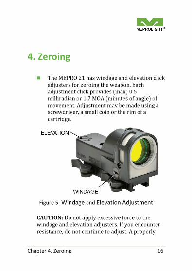
The MEPRO 21 has windage and elevation click adjusters for zeroing the weapon. Each adjustment click provides (max) 0.5 milliradian or 1.7 MOA (minutes of angle) of movement. Adjustment may be made using a screwdriver, a small coin or the rim of a cartridge.
Figure 5: Windage and Elevation Adjustment
CAUTION: Do not apply excessive force to the windage and elevation adjusters. If you encounter resistance, do not continue to adjust. A properly

Chapter 4. Zeroing 17
installed sight with the correct adapter on a serviceable weapon requires only minimal adjustment around the factory set zero.
The click adjusters are marked and have directional arrows. Turning the windage screw clockwise, in the direction of the arrow (marked “R”) moves the mean-point-of-impact (MPI) at the target to the right. Turning the elevation screw counter-clockwise, in the direction of the arrow (marked “UP”) raises the MPI at the target. Therefore, to bring the MEPRO 21 aiming dot into position with the front iron sight, you must turn the adjusters in the opposite direction – if the aiming dot is to the right of the front sight, turn the windage screw clockwise, and if the dot is too high, turn the elevation screw counter-clockwise.
Dry zeroing Dry zeroing is possible when the MEPRO 21 is
mounted on weapons where the front and rear iron sights are left in place. By adjusting the dot to be close to the iron sight point-of-impact, reasonable zeroing for short ranges can be performed without live firing.
Using the iron sights as a guide, the MEPRO 21 aiming dot should be brought into alignment

18 Chapter 4. Zeroing
with the sights such that the dot is slightly higher (several mm) than the top of the front sight and centered on it horizontally.
Live fire zeroing Attach the MEPRO 21 sight firmly to the
weapon, preferably after having been dry zeroed to the iron sights or when not possible, according to the factory set zero.
Aim to a zeroing target at a distance of 25 m. Aim to the target center.
Fire a group of 5 rounds.
Mark the MPI (Mean Point of Impact) and measure the vertical and horizontal distance between the MPI and the OPI (Optimal Point of Impact). See figure 6.

Chapter 4. Zeroing 19
Figure 6: MPI adjustment
NOTE: The OPI is lower than the target center because of bullet trajectory. See figure 7.
Use the elevation and windage adjustment screws to correct the MPI according to the measure taken in the previous step.
Rotate the elevation adjustment screw marked "UP" counter clockwise to raise the MPI and clockwise to lower it.

20 Chapter 4. Zeroing
Rotate the windage adjustment screw marked "R" clockwise to move the MPI to the right and counter clockwise to move it to the left.
Each click of the adjustment screws will move the MPI about 1.25 cm when aiming at a distance of 25 m.
Example: If the MPI is 5 cm below the target center, move it up by turning the adjustment screw marked "UP" 4 clicks counter clockwise. If the MPI is 2.5 cm left of the target center, move it right by turning the adjustment screw marked "R" 2 clicks clockwise.
Zeroing process is complete when the MPI overlaps the OPI.
Range and trajectory This paragraph describes aiming at ranges of
50 through 250 meters and beyond, considering the bullet trajectory.
Following the zeroing process, your weapon and sight are now zeroed to a range of 50 and 250 meters.
Figure 6 describes a bullet trajectory zeroed to a range of 50 and 250 meters. This allows the shooter to make quick adjustments when
Chapter 4. Zeroing 21
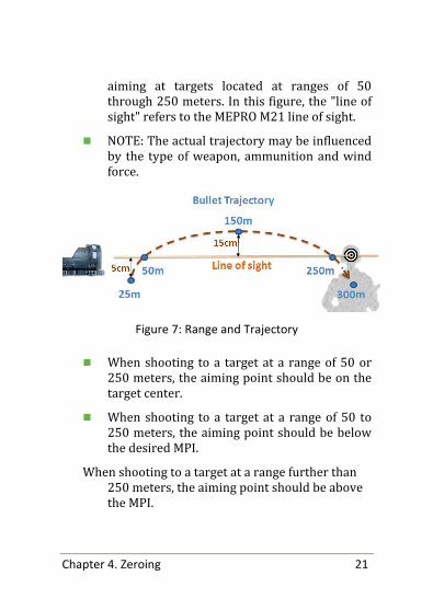
aiming at targets located at ranges of 50 through 250 meters. In this figure, the "line of sight" refers to the MEPRO M21 line of sight.
NOTE: The actual trajectory may be influenced by the type of weapon, ammunition and wind force.
Figure 7: Range and Trajectory
When shooting to a target at a range of 50 or 250 meters, the aiming point should be on the target center.
When shooting to a target at a range of 50 to 250 meters, the aiming point should be below the desired MPI.
When shooting to a target at a range further than 250 meters, the aiming point should be above the MPI.

Chapter 5. Principle of operation 22
5. Principle of operation
The MEPRO 21, dual illuminated, “red dot” reflex sight provides instant, all light aiming without batteries. Whenever there is any available light, illumination of the aiming point is achieved by a fiber optic collector system located around the front top and forward surfaces of the sight. Whenever there is little or no available ambient light, illumination of the aiming point is achieved by a miniature self-powered tritium light source. Transition between the two lighting systems is instantaneous and automatic, according to change in ambient light. This provides good contrast between the aiming dot and the target area.
PLEASE NOTE: Since the light is collected by the fiber optic system, the area of the sight where the collector is located must be kept unobstructed to assure maximum dot brightness.

Chapter 6. Cleaning and general care 23
6. Cleaning and general care
Inspect the MEPRO 21 daily. Inspect the body, lenses and windows for signs of damage, scrapes, cracks or broken pieces.
Remove dust from the lens with rice paper or soft lens cloth.
Remove dust from the fiber optic window with a special cleaning brush (provided).
Remove dust from the body with rice paper or soft cloth.
If the aiming dot appears weak or is only partially visible, it may be dirty. In such a case, the sight may be washed in clear water. In the absence of clear water, a soft cloth or cotton swab can be used to gently clean away any visible dirt from the cavity where the aiming dot is located.
Prevent contact with solvents, oil, petrol etc.
No attempt should be made to disassemble the sight. This may damage the tritium light source or the fiber optic system.

24 Chapter 6. Cleaning and general care
Safety The MEPRO 21 contains a small amount of
radioactive material in the form of gaseous tritium (Hydrogen-3) sealed inside a small glass tube. In this form, the tritium does not present any hazard to the user. If the light source should break, a small amount of tritium will be released to the surrounding surfaces and to the air. Tritium is very weak and can enter the body by only the following ways: breathing, eating, or through an open wound.
If the tritium light source in a MEPRO 21 is broken or is suspected of being broken, the sight should be placed in a sealed plastic bag; and, the person handling it should wash his hands thoroughly with soap and water.
Avoid handling a sight with a broken light source if you have open skin cuts or abrasions. Handling and bagging should be performed in a well ventilated area. Do not eat, drink, or smoke in the presence of a defective unit.
Repair of defective units is only authorized by the manufacturer, MEPROLIGHT, Ltd. Please contact MEPROLIGHT, Ltd. or your local distributor for handling and replacement instructions.

Chapter 7. Technical Specifications & Features 25
7. Technical Specifications & Features
Magnification: Unity (1X) Power Lens Diameter: 30mm Field of View: Unlimited with both eyes open Eye relief: 10 to 600 mm Aiming point diameter
5.5 MOA/4.3 MOA/2 MOA
Other shapes Triangle, Open X, Bulls eye, Ballistic 300-500, Cross
Resolution: Limited by eye only Length: 114 mm (4.53”) Width: 46 mm (1.81”) Height: 56 mm (2.24”) Weight: 230 grams (8 oz) without
weapon adapter

26 Chapter 7. Technical Specifications & Features
Reliability With no moving parts other than the two zeroing adjustments, no electric circuits or batteries - the MEPRO 21 is extremely reliable. The fiber optic system and the tritium illumination system cannot fail because of weak or dead batteries or weather related situations. In addition, the MEPRO 21 is not affected by submergence in water.

Chapter 8. WARRANTY 27
8. WARRANTY
MEPROLIGHT® warrants the MEPRO 21 to the original purchaser against defects in material or workmanship for a period of one year and the illumination for ten years from the date of purchase. In case of failure due to a manufacturing defect within this period, the sight will be repaired or replaced at our option (proof of purchase must be provided and the sight must be returned together with a description of the problem). This limited warranty does not apply to scratches on the lens and does not apply to any defects caused by abuse or misuse, including any attempt at disassembly or servicing not specifically authorized by MEPROLIGHT®. Please contact MEPROLIGHT, Ltd. or your local distributor for warranty service instructions.


Rev. H, Aug. 2012, P.N. 5626900110
P.O.Box 26. 58 Hazait Street, Or-Akiva Industrial Park, Or-Akiva 30600, Israel. Tel: + 972 4 6244111 Fax: + 972 4 6244123 email: [email protected]


