9
Mercury Chamber Considerations V. Graves IDS-NF Target Studies July 2011
| Date post: | 21-Dec-2015 |
| Category: |
Documents |
| View: | 222 times |
| Download: | 2 times |

Mercury Chamber Considerations
V. Graves
IDS-NF Target Studies
July 2011
2 Managed by UT-Battellefor the U.S. Department of Energy Mercury Chamber Considerations, July 2011
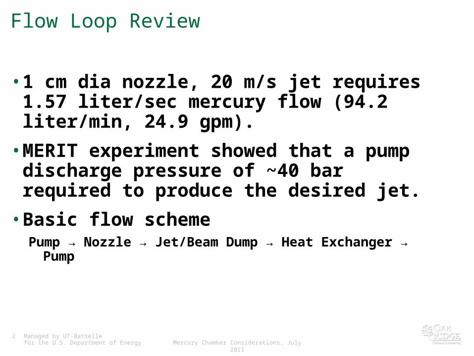
Flow Loop Review
• 1 cm dia nozzle, 20 m/s jet requires 1.57 liter/sec mercury flow (94.2 liter/min, 24.9 gpm).
• MERIT experiment showed that a pump discharge pressure of ~40 bar required to produce the desired jet.
• Basic flow schemePump → Nozzle → Jet/Beam Dump → Heat Exchanger → Pump
3 Managed by UT-Battellefor the U.S. Department of Energy Mercury Chamber Considerations, July 2011
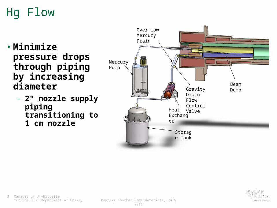
Hg Flow
• Minimize pressure drops through piping by increasing diameter– 2" nozzle supply piping
transitioning to 1 cm nozzle
Overflow Mercury Drain
Mercury Pump
Gravity Drain Flow Control Valve
Storage Tank
Heat Exchanger
Beam Dump
4 Managed by UT-Battellefor the U.S. Department of Energy Mercury Chamber Considerations, July 2011
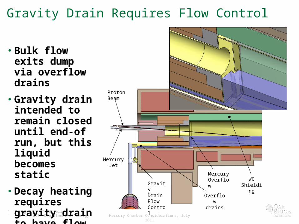
Gravity Drain Requires Flow Control
• Bulk flow exits dump via overflow drains
• Gravity drain intended to remain closed until end-of run, but this liquid becomes static
• Decay heating requires gravity drain to have flow control
Mercury Jet
Proton Beam
Mercury Overflow
Gravity Drain Flow Control
Overflow drains
WC Shielding

5 Managed by UT-Battellefor the U.S. Department of Energy Mercury Chamber Considerations, July 2011
Mercury Chamber Basics
• Chamber serves as both jet and beam dumps– Chamber must encompass the nozzle tip
• No openings into chamber during operation– Mercury flows in a closed loop
– Likely will be double-walled for mercury containment, possibly water cooled
• No embedded sensors
• Gravity drain of mercury required
• Penetrations (ports) into chamber– Nozzle
– Hg drains (overflow and maintenance)
– Vents (in and out)
– Beam windows (upstream and downstream)
– Cooling?
6 Managed by UT-Battellefor the U.S. Department of Energy Mercury Chamber Considerations, July 2011
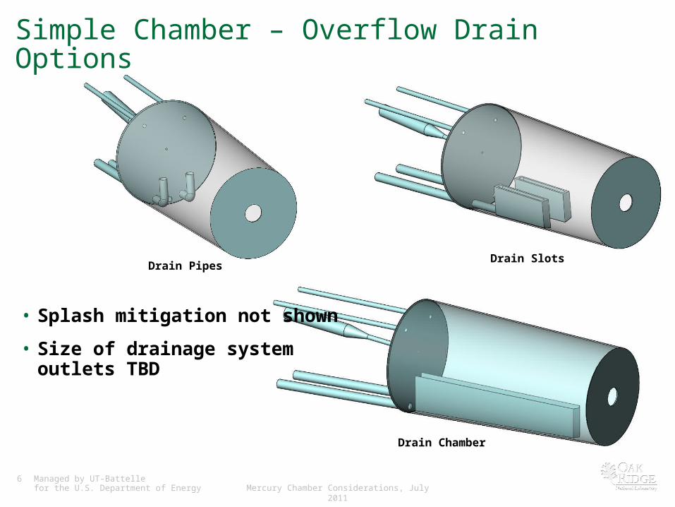
Simple Chamber – Overflow Drain Options
• Splash mitigation not shown
• Size of drainage system outlets TBD
Drain PipesDrain Slots
Drain Chamber

7 Managed by UT-Battellefor the U.S. Department of Energy Mercury Chamber Considerations, July 2011
Mercury Chamber Ports
• Chamber requires several ports
• Sizes likely to increase due to remote handling requirements
Vents (In/Out)
Jet Nozzle
Overflow Drains
Maintenance Drain (Valved)
Beam Pipe
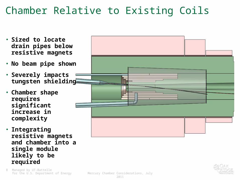
8 Managed by UT-Battellefor the U.S. Department of Energy Mercury Chamber Considerations, July 2011
Chamber Relative to Existing Coils
• Sized to locate drain pipes below resistive magnets
• No beam pipe shown
• Severely impacts tungsten shielding
• Chamber shape requires significant increase in complexity
• Integrating resistive magnets and chamber into a single module likely to be required

9 Managed by UT-Battellefor the U.S. Department of Energy Mercury Chamber Considerations, July 2011
Upstream Solenoids Affect Design
• Long piping required
• Remote removal / insertion more difficult
• Beam trajectory impacted– Dictates the location of
upstream accelerator
– Ramifications of inaccurate field map?
• More utility connections interfere with beam path


![IDS-NF Accelerator Baseline The Neutrino Factory [1, 2] based on the muon storage ring will be a precision tool to study the neutrino oscillations.It may.](https://static.documents.pub/doc/80x56/5a4d1ad97f8b9ab0599740ae/ids-nf-accelerator-baseline-the-neutrino-factory-1-2-based-on-the-muon-storage.jpg)


