28


www.pivotcycles.com480-467-2920PARTS SCHEMATIC
NUMBER PART NAME DESCRIPTION Torque *
* = grease = anti-seize = anti-seize or grease = loctite 243
FIREBIRD
15 FP-LNK-LL-GLD-V5-R1 LINK LOWER GOLD VER5 REV1
16 FP-BRG-6802-LLBMAX 6802 LLB MAX
17 FP-SLV-LL-25MM SLEEVE LOWER LINK 25MM
18 FP-SLV-LL-28MM SLEEVE LOWER LINK 28MM
19 FP-LNK-UL-85MM-V2 LINK UPPER 85MM VER2
23 FP-BRG-608-LLBMAX 608 LLB MAX
24 FP-BRG-608-FE2RSSPMX 608 FE 2RS SP MX
50 FP-BLT-M8*39-SIL BOLT 8X39 SILVER 13 Nm (10 lb·ft)
51 FP-LNK-FD-SIL-V1-R1 LINK FRONT DERAILLEUR SILVER VER 1 REV 1
52 FP-STP-FFD-V1 STOP FLOATING FRONT DERAILLEUR V1
53 FP-WSH-5I*9O*15W WASHER 5I X 9O X 15W
54 FP-BRG-685-LLB 685 LLB
55 FP-BRG-3802-2RSP 3802 2RS-P
56 FP-CAP-LL-11I CAP LOWER LINK 11ID
57 FP-SCW-SCK-M6*10 SCREW SOCKET 6X10 7 Nm (5 lb·ft)58 FP-SCW-BTN-M5*10 SCREW BUTTON 5X10 3 Nm (26 in·lb)59 FP-SCW-RND-M5*25 SCREW ROUND 5X25 4 Nm (35 in·lb)61 FP-SCW-FLT-M6*10 SCREW FLAT 6X10 5 Nm (44 in·lb)63 FP-SCW-FLT-M5*12 SCREW FLAT 5X12 4 Nm (35 in·lb)64 FP-SCW-FLT-M5*25 SCREW FLAT 5X25 4 Nm (35 in·lb)65 FP-SPR-EXT-10.5O*52.25 SPRING EXTENSION 10.5X52.25
66 FP-BLT-M14*69-GLD BOLT 14X69 GOLD 35 Nm (27 lb·ft)67 FP-BLT-M8*17 BOLT 8X17 13 Nm (10 lb·ft)68 FP-GDE-CHN-ISCG-V1 GUIDE CHAIN ISCG VER1
69a FP-RDH-QR-9MM-BLK-V1 REAR DERAILLEUR HANGER QR 9MM BLACK V1
69b FP-RDH-TA-12MM-BLK-V1 REAR DERAILLEUR HANGER THROUGH AXLE 12MM BLACK V1
70 FP-WSH-UL-3MM-BLK WASHER UPPER LINK 3MM BLACK
71 FP-WSH-8I*12O*1W WASHER 8I X 12O X 1W
72a FP-SCW-RND-M8*8 SCREW ROUND 8X8 7 Nm (5 lb·ft)
72b FP-SCW-SCK-M5*10 SCREW SOCKET 5X10 7 Nm (5 lb·ft)
73 DT SWISS 142 RWS DT SWISS 142 RWS
50
24
67
2318
1617
15
63
57
56
55
58
52
61
5965
54
64
53
68
66
16
16
16
16
16
1650
58
58
51
66
67
67
16
19
61
69a 72a
70
71
71
67
69b
72b73
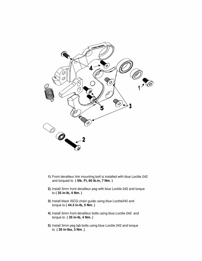
1) Front derailleur link mounting bolt is installed with blue Loctite 242
and torqued to ( 5lb. Ft, 60 lb.in, 7 Nm. )
2) Install 3mm front derailleur peg with blue Loctite 242 and torque
to ( 35 in-lb, 4 Nm. )
3) Install black ISCG chain guide using blue Loctite242 and
torque to ( 44.3 in-lb, 5 Nm. )
4) Install 3mm front derailleur bolts using blue Loctite 242 and
torque to ( 35 in-lb, 4 Nm. )
5) Install 3mm peg tab bolts using blue Loctite 242 and torque
to ( 26 in-lbs, 3 Nm. )

www.pivotcycles.com 1.877.857.4868 1
Document Contents:
1. Setting Sag on FOX Float DPS and Float X Rear shocks2. Setting Rebound damping on FOX Float DPS and Float X Rear Shocks3. Setting Compression damping on FOX Float DPS and Float X Rear Shocks4. Setting up FOX Float X2 Air5. Setting up FOX Float air fork pressure6. Setting up FOX Float air fork compression and rebound damping
SUSPENSION SETUP GUIDE
For your Pivot suspension equipped bike to pedal and descend at its best, it is important to tune the suspension properly. Use this guide to familiarize yourself with the Pivot suspension setup procedures and as a baseline for tuning to your individual riding needs.
Performance. Redefined.
SUSPENSION SETUP GUIDE
www.pivotcycles.com 1.877.857.4868 2
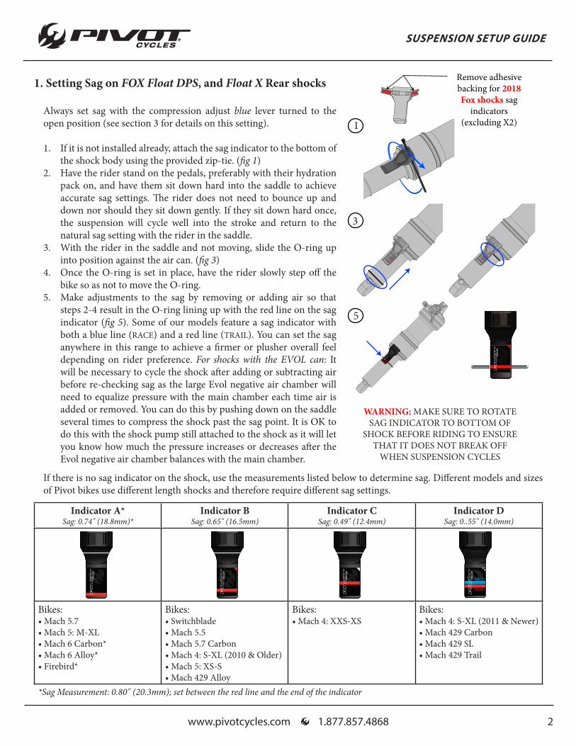
1. Setting Sag on FOX Float DPS, and Float X Rear shocks
Always set sag with the compression adjust blue lever turned to the open position (see section 3 for details on this setting).
1. If it is not installed already, attach the sag indicator to the bottom of the shock body using the provided zip-tie. (fig 1)
2. Have the rider stand on the pedals, preferably with their hydration pack on, and have them sit down hard into the saddle to achieve accurate sag settings. The rider does not need to bounce up and down nor should they sit down gently. If they sit down hard once, the suspension will cycle well into the stroke and return to the natural sag setting with the rider in the saddle.
3. With the rider in the saddle and not moving, slide the O-ring up into position against the air can. (fig 3)
4. Once the O-ring is set in place, have the rider slowly step off the bike so as not to move the O-ring.
5. Make adjustments to the sag by removing or adding air so that steps 2-4 result in the O-ring lining up with the red line on the sag indicator (fig 5). Some of our models feature a sag indicator with both a blue line (RACE) and a red line (TRAIL). You can set the sag anywhere in this range to achieve a firmer or plusher overall feel depending on rider preference. For shocks with the EVOL can: It will be necessary to cycle the shock after adding or subtracting air before re-checking sag as the large Evol negative air chamber will need to equalize pressure with the main chamber each time air is added or removed. You can do this by pushing down on the saddle several times to compress the shock past the sag point. It is OK to do this with the shock pump still attached to the shock as it will let you know how much the pressure increases or decreases after the Evol negative air chamber balances with the main chamber.
WARNING: MAKE SURE TO ROTATE SAG INDICATOR TO BOTTOM OF
SHOCK BEFORE RIDING TO ENSURE THAT IT DOES NOT BREAK OFF
WHEN SUSPENSION CYCLES
Remove adhesivebacking for 2018 Fox shocks sag
indicators(excluding X2)1
3
5
Indicator A*Sag: 0.74" (18.8mm)*
Indicator BSag: 0.65" (16.5mm)
Indicator CSag: 0.49" (12.4mm)
Indicator DSag: 0..55" (14.0mm)
Bikes:• Mach 5.7• Mach 5: M-XL• Mach 6 Carbon*• Mach 6 Alloy*• Firebird*
Bikes:• Switchblade• Mach 5.5• Mach 5.7 Carbon• Mach 4: S-XL (2010 & Older) • Mach 5: XS-S• Mach 429 Alloy
Bikes:• Mach 4: XXS-XS
Bikes:• Mach 4: S-XL (2011 & Newer)• Mach 429 Carbon• Mach 429 SL• Mach 429 Trail
*Sag Measurement: 0.80" (20.3mm); set between the red line and the end of the indicator
If there is no sag indicator on the shock, use the measurements listed below to determine sag. Different models and sizes of Pivot bikes use different length shocks and therefore require different sag settings.

SUSPENSION SETUP GUIDE
www.pivotcycles.com 1.877.857.4868 3
2. Setting Rebound damping on FOX Float DPS and Float X Rear Shocks:
We set rebound from the most open or fastest position, so start by turning the red rebound dial counterclockwise all the way out and then follow the guidelines below per model:
• Mach 4, 429SL, and Mach 5.7: Turn red dial in clockwise 0-6 clicks in depending on rider weight. A sub 130lb rider is at the full out or fastest setting. Average is 4 clicks in.
• Mach 429 Trail: Turn red dial in clockwise 3-8 clicks in depending on rider weight. Average is 5 clicks in.• Switchblade and Mach 5.5: Turn red dial in clockwise 5-10 clicks in depending on rider weight. Average is 6
clicks in.• Mach 6 or Firebird with Float X or Float DPS: Turn red dial in clockwise 9-13 clicks in depending on rider
weight.
3. Setting Compression damping on FOX Float DPS and Float X Rear Shocks:
Because all dw-link® equipped Pivot bikes pedal so efficiently, we use the compression lever as a tuning tool for rider weight and compression support. All bikes can be run with the blue lever in full open and perform very well. On Float DPS shocks, this means the lever is turned towards the opposite side of the air valve. In the case of the Float X, this means that the lever will be flipped towards the remote reservoir. Lighter riders under 160lbs will generally run in the full open position most of the time. Riders in the 170lb+ range and more aggressive riders who like the feel of more mid-stroke support will generally prefer the middle setting. The firm setting is great for your ride to the trail, long fire road climbs, and smooth XC race courses where a more locked out feel is desired.
All Factory Series Float X and Float DPS shocks also feature three additional options that affect the open setting via the black knob. This knob needs to be lifted slightly to turn to one of the three designated options. #1 is the most open, or least amount of compression damping, and #3 is the firmest (but still slightly less firm then the middle position of the blue lever). You can experiment with all of these options to find the setting that provides the best compression support and plushest feel for your weight and riding style. Other than running in the full firm mode on rocky descents, all settings are designed to work well in a wide variety of terrain and rider weights.

SUSPENSION SETUP GUIDE
www.pivotcycles.com 1.877.857.4868 4
4. FOX Float X2 Air:Start by setting sag using the same process as the Float X and Float DPS shocks (page 2). The sag indicator on this shock is located on the oil reservoir rather than attached to the air sleeve. If there is no sag indicator on the oil reservoir use the measurements listed below to determine sag. Different models and sizes of Pivot bikes use different length shocks and therefore require different sag settings. The bike models for each sag setting are listed under the respective diagrams.
Damping AdjustmentsThe X2 air shock has tuning options well beyond the scope of what we can cover here. Not only can the shock be tuned through the use of the HSC, LSC, HSR, and LSR knobs, but it can also be tuned via the amount of air pressure in the shock and the addition or removal of air volume spacers to change the spring curve characteristics. We have settled on an air spring curve that has proven to be optimized for a wide range of riders from a sport level to our World Cup DH team, so changing the Pivot factory air spring curve characteristics is not really necessary.
We recommend 30% sag on the Float X2 Air. Based on this sag setting you can record your air pressure and use FOX’s tuning chart copied on the right to set your High Speed Compression damping (HSC), Low Speed Compression damping (LSC), High Speed Rebound damping (HSR), and Low Speed Rebound damping (LSR). These settings are also applicable to Performance series Float X2 air shocks that feature only the LSC and LSR adjustments.
The suggested settings differ based on the which model year shock is spec'd on your bike. The performance of the shocks are identical between model years, however, due to valving changes, the suggested settings have shifted in the usable range of the tuning options. To determine which shock is spec'd on your bike look for a set screw on the bottom of the air can, in line with the fill valve. The 2018 shocks will have a set screw, the 2017 shocks will not. The photos below will help illustrate the difference between the shocks.
8.5” x2.5” Shock Spec
.80”(20.3mm)
9.5” x 3” Shock Spec
.90”(23mm)
.67”(17mm)
.57”(14.5mm)
7.875” x 2” Shock Spec
Bikes: •Switchblade •Mach 5.5
Bikes: •Firebird •Mach 6
Bikes: •Phoenix
Fox Float X2 MY 2017No set screw
Fox Float X2 MY 2018Set screw
SUSPENSION SETUP GUIDE
www.pivotcycles.com 1.877.857.4868 5
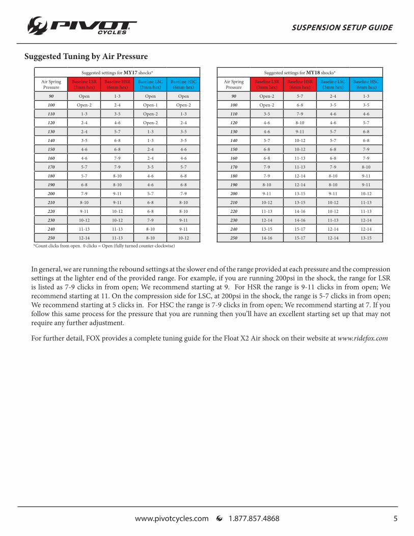
In general, we are running the rebound settings at the slower end of the range provided at each pressure and the compression settings at the lighter end of the provided range. For example, if you are running 200psi in the shock, the range for LSR is listed as 7-9 clicks in from open; We recommend starting at 9. For HSR the range is 9-11 clicks in from open; We recommend starting at 11. On the compression side for LSC, at 200psi in the shock, the range is 5-7 clicks in from open; We recommend starting at 5 clicks in. For HSC the range is 7-9 clicks in from open; We recommend starting at 7. If you follow this same process for the pressure that you are running then you’ll have an excellent starting set up that may not require any further adjustment.
Suggested settings for MY17 shocks*
Air Spring Pressure
Baseline LSR (3mm hex)
Baseline HSR (6mm hex)
Baseline LSC (3mm hex)
Baseline HSC (6mm hex)
90 Open 1-3 Open Open
100 Open-2 2-4 Open-1 Open-2
110 1-3 3-5 Open-2 1-3
120 2-4 4-6 Open-2 2-4
130 2-4 5-7 1-3 3-5
140 3-5 6-8 1-3 3-5
150 4-6 6-8 2-4 4-6
160 4-6 7-9 2-4 4-6
170 5-7 7-9 3-5 5-7
180 5-7 8-10 4-6 6-8
190 6-8 8-10 4-6 6-8
200 7-9 9-11 5-7 7-9
210 8-10 9-11 6-8 8-10
220 9-11 10-12 6-8 8-10
230 10-12 10-12 7-9 9-11
240 11-13 11-13 8-10 9-11
250 12-14 11-13 8-10 10-12
Suggested settings for MY18 shocks*
Air Spring Pressure
Baseline LSR (3mm hex)
Baseline HSR (6mm hex)
Baseline LSC (3mm hex)
Baseline HSC (6mm hex)
90 Open-2 5-7 2-4 1-3
100 Open-2 6-8 3-5 3-5
110 3-5 7-9 4-6 4-6
120 4-6 8-10 4-6 5-7
130 4-6 9-11 5-7 6-8
140 5-7 10-12 5-7 6-8
150 6-8 10-12 6-8 7-9
160 6-8 11-13 6-8 7-9
170 7-9 11-13 7-9 8-10
180 7-9 12-14 8-10 9-11
190 8-10 12-14 8-10 9-11
200 9-11 13-15 9-11 10-12
210 10-12 13-15 10-12 11-13
220 11-13 14-16 10-12 11-13
230 12-14 14-16 11-13 12-14
240 13-15 15-17 12-14 12-14
250 14-16 15-17 12-14 13-15
*Count clicks from open. 0 clicks = Open (fully turned counter-clockwise)
Suggested Tuning by Air Pressure
For further detail, FOX provides a complete tuning guide for the Float X2 Air shock on their website at www.ridefox.com

SUSPENSION SETUP GUIDE
www.pivotcycles.com 1.877.857.4868 6
5. FOX Float Air Fork Pressure: To set fork sag use the charts below as a recommended starting point:
6. FOX Float Air Fork Rebound and Compression Damping:
Setting rebound damping on FOX Forks:
We set rebound from the most open or fastest position, so start by turning the red rebound dial on the bottom of the right fork leg counterclockwise all the way out and then follow the guidelines below:
• Float 32, 34, 36 Fit: Turn red dial clockwise in 5-8 clicks in (depending on rider weight). Most riders are safe with 6 clicks in as a starting point.
Setting Low Speed Compression damping on FOX Forks:
We set compression from the most open or fastest position, so start by turning the black compression inner dial on the top of the right fork leg counterclockwise all the way out and then follow the guidelines below:
• Float 32, 34, 36 Fit: Turn black dial clockwise in 2-8 clicks in (depending on rider weight). Most riders should feel comfortable with 5 clicks in as a starting point. A rider under 120lbs would start with 2 clicks in.
RIDER WEIGHT (lbs) 32 FLOAT Pressure 34 FLOAT Pressure 36 FLOAT Pressure
120-130 57 psi/ 3.9 bar 45 psi/ 3.1 bar 40 psi/ 2.8 bar
130-140 61 psi/ 4.2 bar 48 psi/ 3.3 bar 41 psi/ 2.8 bar
140-150 66 psi/ 4.5 bar 51 psi/ 3.5 bar 43 psi/ 3.0 bar
150-160 71 psi/ 4.9 bar 53 psi/ 3.7 bar 46 psi/ 3.2 bar
160-170 76 psi/ 5.2 bar 56 psi/ 3.9 bar 51psi/ 3.5 bar
170-180 82 psi/ 5.6 bar 58 psi/ 4.0 bar 55 psi/ 3.8 bar
180-190 87 psi/ 6.0 bar 63 psi/ 4.3 bar 59 psi/ 4.1 bar
190-200 92 psi/ 6.3 bar 68 psi/ 4.7 bar 63 psi/ 4.3 bar
200-210 98 psi/ 6.7 bar 72 psi/ 5.0 bar 67 psi/ 4.6 bar
210-220 103 psi/ 7.1 bar 77 psi/ 5.3 bar 71 psi/ 4.8 bar
220-230 108 psi/ 7.4 bar 82 psi/ 5.6 bar 75 psi/ 5.2 bar
230-240 113 psi/ 7.8 bar 86 psi/ 5.9 bar 79 psi/ 5.4 bar
240-250 119 psi/ 8.2 bar 91psi/ 6.3 bar 83 psi/ 5.7 bar
www.pivotcycles.com 1.877.857.4868
1.
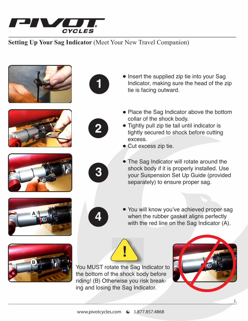
Setting Up Your Sag Indicator (Meet Your New Travel Companion)
!
1Insert the supplied zip tie into your Sag Indicator, making sure the head of the zip tie is facing outward.
2Place the Sag Indicator above the bottom collar of the shock body.Tightly pull zip tie tail until indicator is tightly secured to shock before cutting excess.Cut excess zip tie.
BYou MUST rotate the Sag Indicator to the bottom of the shock body before riding! (B) Otherwise you risk break-ing and losing the Sag Indicator.
3The Sag Indicator will rotate around the shock body if it is properly installed. Use your Suspension Set Up Guide (provided separately) to ensure proper sag.
4You will know you’ve achieved proper sag when the rubber gasket aligns perfectly with the red line on the Sag Indicator (A).
A
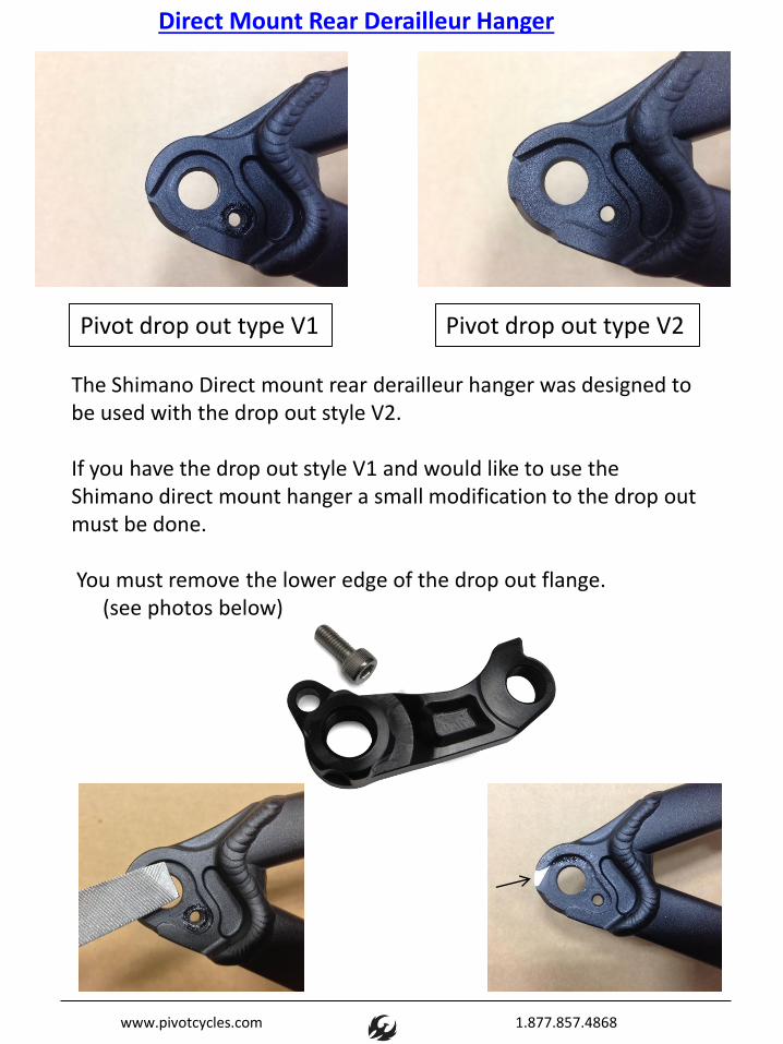
Direct Mount Rear Derailleur Hanger
Pivot drop out type V1 Pivot drop out type V2
The Shimano Direct mount rear derailleur hanger was designed to be used with the drop out style V2. If you have the drop out style V1 and would like to use the Shimano direct mount hanger a small modification to the drop out must be done. You must remove the lower edge of the drop out flange. (see photos below)
www.pivotcycles.com 1.877.857.4868


The Firebird has always been revered for its unique combination of climbing traction, acceleration, and descending capabilities.
The new Firebird 27.5-inch takes everything that’s great about the original and makes it better. Within our line of very versatile bikes it stands out because it truly rewards and inspires confidence for an aggressive rider.

ALUMINUM TECHNOLOGY
When we launched Pivot Cycles in 2007, we set out to develop the best mountain bikes in the world (regardless of material) and what developed was a line of aluminum bikes that set new benchmarks performance, weight and stiffness. Now nearly 6 years in, we’ve continued to develop, refine and re-define our line of aluminum full-suspension bikes so that these models would continue to be the best performing bikes in the world.
We go about things in a very different manner here at Pivot. You could definitely say we take the high road to building the best aluminum bikes in the world.
In the Beginning

ALUMINUM TECHNOLOGY
First and Foremost, we have full manufacturing and proto-typing capabilities within our factory in Tempe. Arizona. Every Pivot alloy frame begins on the drawing board, but quickly moves to proto-typing within our own building. We have 4 CNC machining centers, mills, lathes, frame jigs, tube forming, welding, and testing capabilities in house.
It is common for a new model to have been though as many as 6 different proto-type variations and been in development for 2 years before it ever enters into production. Having these capabilities at Pivot gives us an advantage that few of our competitors have.
Proto-typing

ALUMINUM TECHNOLOGY
When we develop a new model,the tooling to produce that model ismade in house. We developeverything needed to move the biketo production in the manner in whichwe want it made. We control every detail from how the tubes and parts are loaded into the fixture, how the frame is tacked and the order in which it is welded, checked, aligned and final machined.
Often times for a new model, thefirst 50 -75 bikes are made inhouse before we bring the bikes to production.
Proto-typing Continued

ALUMINUM TECHNOLOGY
Our goal is to manufacture the best bikes in the world and to do that we need to employ the best manufacturing capabilities in the world. In this case, Taiwan is the place. We wanted the best tube forming, forging, heat treating, and finishing capabilities for building bicycles and it is no secret that Taiwan is the world leader for bicycle production. The key is to have a manufacturing partner that can harness these capabilities and manufacture a Pivot to our high standards.
Fortunately, we have a close partner in Taiwan that Chris has known for over 10 years. They are a relatively small, family owned company that has been producing high end road frames for a small number of the most elite companies in the world (many of the names might surprise you). They have a penchant for high quality and a pride in their work that matches our own. With our partnership, we developed the process for building Pivot frames. We have our own production and assembly line as well as warehousing within their factory. Their family is like our family. The same people have been welding and assembling Pivot frames since the day we began.
So why don’t we just build the bikes in house?

ALUMINUM TECHNOLOGY
It’s not enough that we proto-type in house, develop the manufacturing process, and train our partners to build our bikes. There’s so much more to it than that. For many things, we continue to manufacture in house, supply from the US, or look outside of the bicycle industry to push the boundaries of what ispossible.
Some of the higher tolerance hardware and machined parts used in our Alloy frames are manufactured at Pivot and sent over to be welded and/or assembled into our frames. We also use a proprietary weld rod that is US made, and results in a stronger, better looking weld. It is about 5 times as expensive but produces a better frame so we send it from the US to Taiwan so that we know we are producing only the best products in the world.
But, there is still more to the story….

ALUMINUM TECHNOLOGY
Look at the bottom bracket area of any Pivot alloy frame and you can see that we really have something truly unique going with designs that focus on frame stiffness, high tolerances and light weight. The bottom bracket area (and several other forged parts) on our frames are made using a 3D forging process that is not common to the cycling world. To achieve our design goals on these parts we went outside the industry to a company that produces the A-arm forgings for BMW’s M and Audi’s R series vehicles. This is just another example of how we are redefining what is possible by pushing the boundaries of technology and manufacturing in order to produce the best bikes in the world.
One of the areas where we have really pushed the limits in our frame designs is in forging technology.

ALUMINUM TECHNOLOGY
Our goal is to manufacture the best bikes in the world and to do that we need to employ the best manufacturing capabilities in the world. In this case, Taiwan is the place. We wanted the best tube forming, forging, heat treating, and finishing capabilities for building bicycles and it is no secret that Taiwan is the world leader for bicycle production. The key is to have a manufacturing partner that can harness these capabilities and manufacture a Pivot to our high standards.
Fortunately, we have a close partner in Taiwan that Chris has known for over 10 years. They are a relatively small, family owned company that has been producing high end road frames for a small number of the most elite companies in the world (many of the names might surprise you). They have a penchant for high quality and a pride in their work that matches our own. With our partnership, we developed the process for building Pivot frames. We have our own production and assembly line as well as warehousing within their factory. Their family is like our family. The same people have been welding and assembling Pivot frames since the day we began.
Every Pivot frame is assembled and then checked by a Pivot employee. We go through 28 detailed steps to make sure your Pivot frame is absolutely perfect.
No detail is left to the imagination and our ultimate goal is to deliver a bike that exceeds your every expectation. We like to think of our frames as a functional piece of engineering art where everything has a purpose, every detail has a function and ultimately what you experience is a bike where the technology is seamless and the ride is perfection.
Quality Control
ALUMINUM TECHNOLOGY
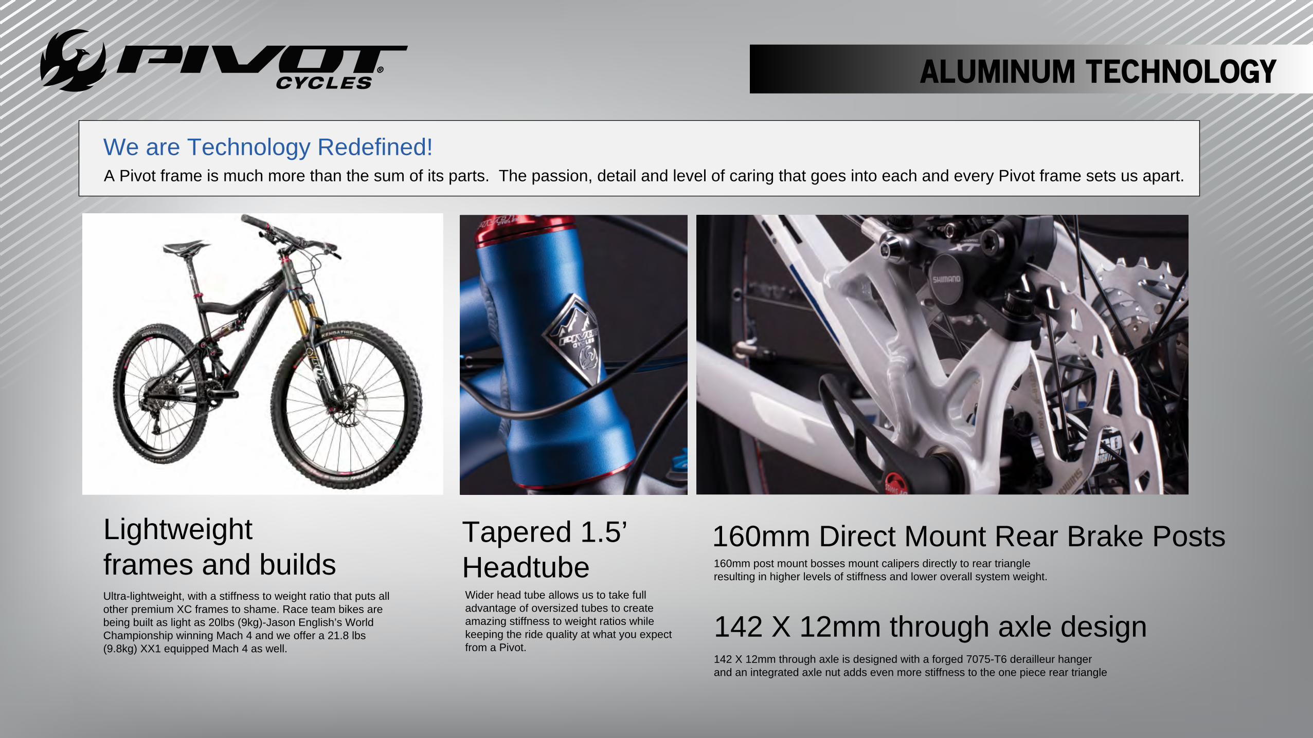
A Pivot frame is much more than the sum of its parts. The passion, detail and level of caring that goes into each and every Pivot frame sets us apart.
160mm Direct Mount Rear Brake Posts160mm post mount bosses mount calipers directly to rear triangle resulting in higher levels of stiffness and lower overall system weight.
Tapered 1.5’ HeadtubeWider head tube allows us to take full advantage of oversized tubes to create amazing stiffness to weight ratios while keeping the ride quality at what you expect from a Pivot.
Lightweightframes and buildsUltra-lightweight, with a stiffness to weight ratio that puts all other premium XC frames to shame. Race team bikes are being built as light as 20lbs (9kg)-Jason English’s World Championship winning Mach 4 and we offer a 21.8 lbs (9.8kg) XX1 equipped Mach 4 as well.
142 X 12mm through axle design142 X 12mm through axle is designed with a forged 7075-T6 derailleur hanger and an integrated axle nut adds even more stiffness to the one piece rear triangle
We are Technology Redefined!

A Pivot frame is much more than the sum of its parts. The passion, detail and level of caring that goes into each and every Pivot frame sets us apart.
ALUMINUM TECHNOLOGY
DW-Link with Carbon Top Plate
Press Fit 92 BBPF92 bottom bracket 92mm shell developed by Pivot with Shimanoallows for wider pivots and better bearing support for increasedframe strength and stiffness while maintaining better control over thebikes chain-line for optimal shifting performance and accuracy.
Forged Alloy Derailleur HangerForged 7075-T6 derailleur hanger with integrated axle nut.Hollowed from the inside out for maximum weight reduction and
capped with a carbon top plate for incredible stiffness. Pivot alloy frames feature a dw-link with a unique double row bearing design bringing an even higher level of bearing durability and frame stiffness to all our aluminum frame designs.
ALUMINUM TECHNOLOGY
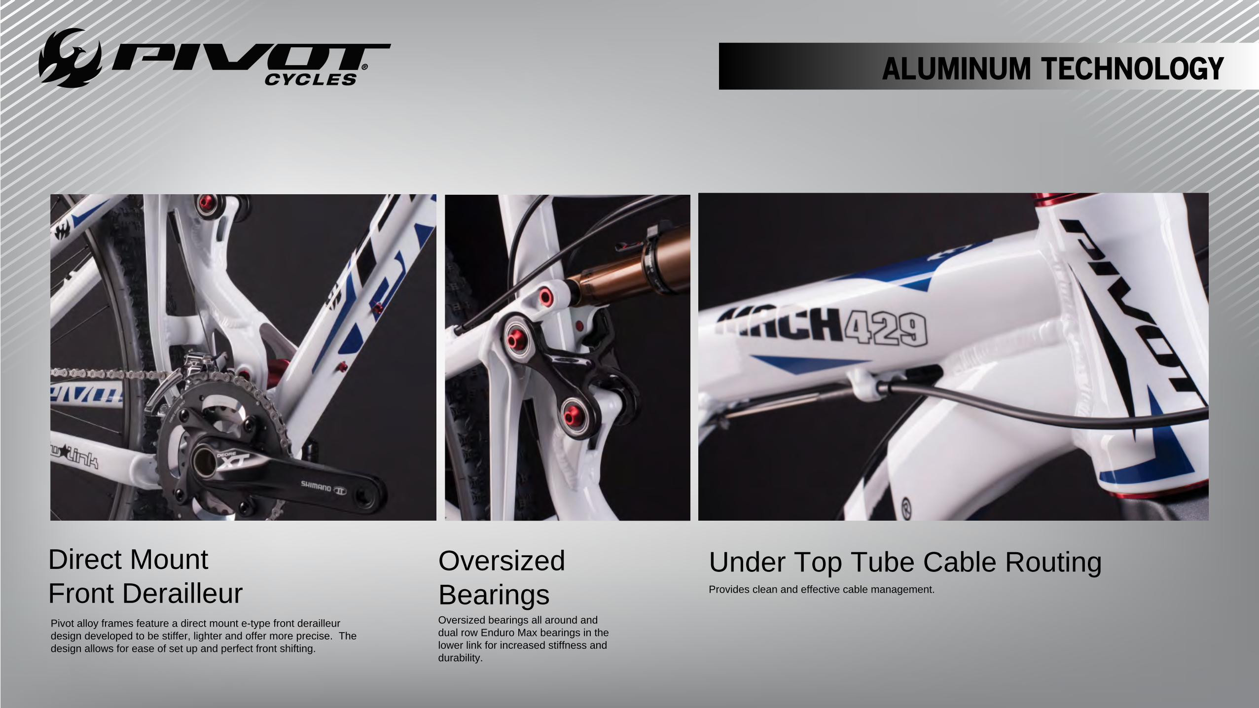
Direct Mount Front Derailleur
Oversized BearingsOversized bearings all around and dual row Enduro Max bearings in the lower link for increased stiffness and durability.
Under Top Tube Cable RoutingProvides clean and effective cable management.
Pivot alloy frames feature a direct mount e-type front derailleur design developed to be stiffer, lighter and offer more precise. The design allows for ease of set up and perfect front shifting.
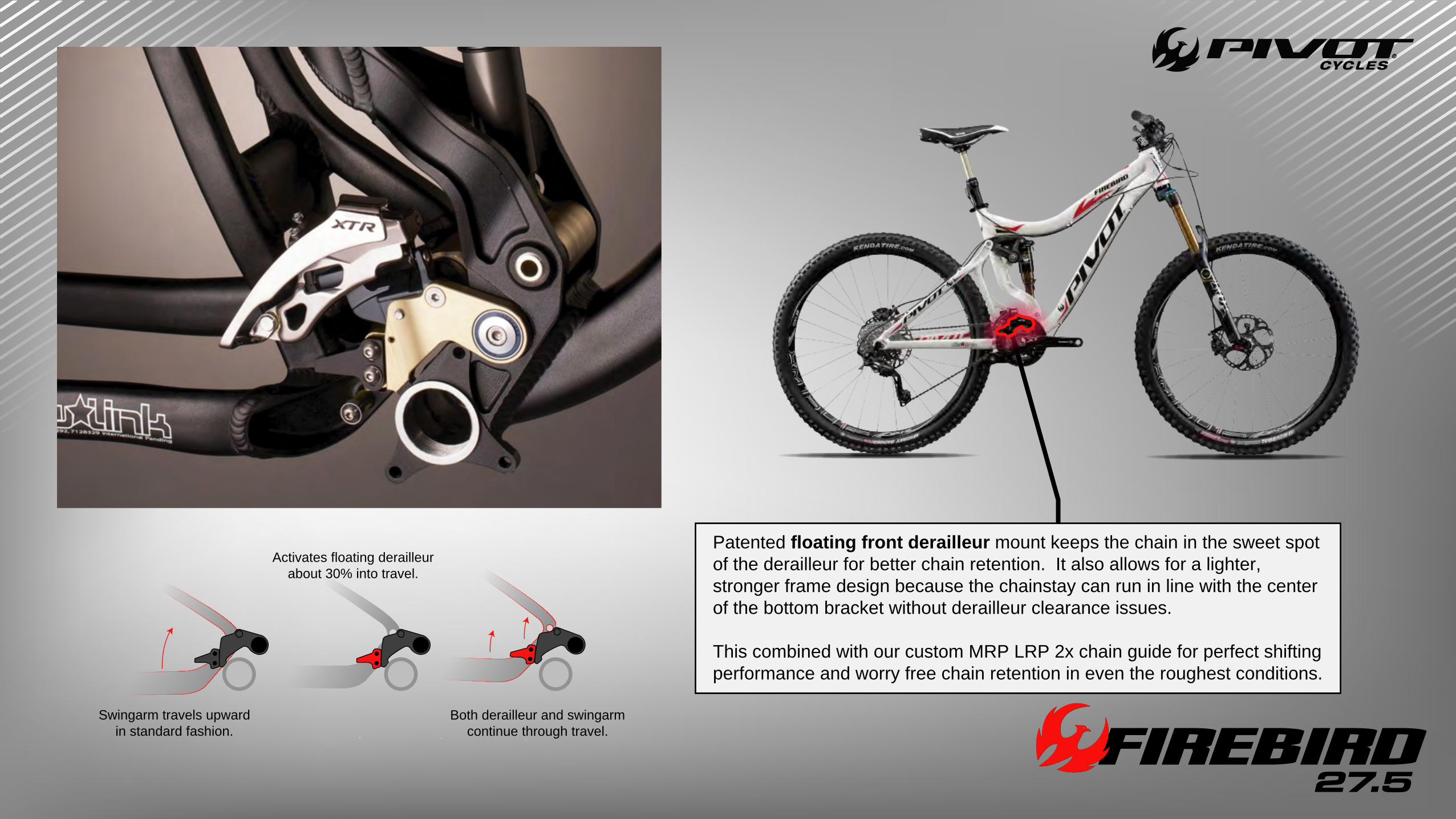
Patented floating front derailleur mount keeps the chain in the sweet spot of the derailleur for better chain retention. It also allows for a lighter, stronger frame design because the chainstay can run in line with the center of the bottom bracket without derailleur clearance issues.
This combined with our custom MRP LRP 2x chain guide for perfect shifting performance and worry free chain retention in even the roughest conditions.
Activates floating derailleurabout 30% into travel.
Both derailleur and swingarmcontinue through travel.
Swingarm travels upwardin standard fashion.

73mm threaded BB shell compatible with all threaded BB designs for maximum compatibility with products in the long travel trail/gravity category. Includes ISCG 05 mounts.
Full 1.5 head tube with custom Pivot angled headset design optimizes the 27.5” Firebird making it the ultimate extreme enduro machine.

142mm x 12 rear through axle and 160mm post mount dropouts for maximum frame stifness.
Pivot Specific, custom valved Fox Float or Float X CTD shock technology featuring increased rider tunability and incredible small bump sensitivity.


![PUBLIC LAW 85-67-JUNE 29, 1957 [71 STAT.210 PUBLIC LAW 85-67-JUNE 29, 1957 [71 STAT. Public Law 85-67 June 29, 195 7 [H. R. 6287] Dep artments of Labor, and Health, Education, and](https://static.documents.pub/doc/80x56/5e2c166f611432794a728765/public-law-85-67-june-29-1957-71-stat-210-public-law-85-67-june-29-1957-71.jpg)


