Information is subject to change without notice. Nortel Networks reserves the right to make changes in design or components as progress in engineering and manufacturing may warrant. This equipment has been tested and found to comply with the limits for a Class A digital device pursuant to Part 15 of the FCC rules, and the radio interference regulations of Industry Canada. These limits are designed to provide reasonable protection against harmful interference when the equipment is operated in a commercial environment. This equipment generates, uses and can radiate radio frequency energy, and if not installed and used in accordance with the instruction manual, may cause harmful interference to radio communications. Operation of this equipment in a residential area is likely to cause harmful interference in which case the user will be required to correct the interference at their own expense.
SL-1 and Meridian 1 are trademarks of Nortel Networks.
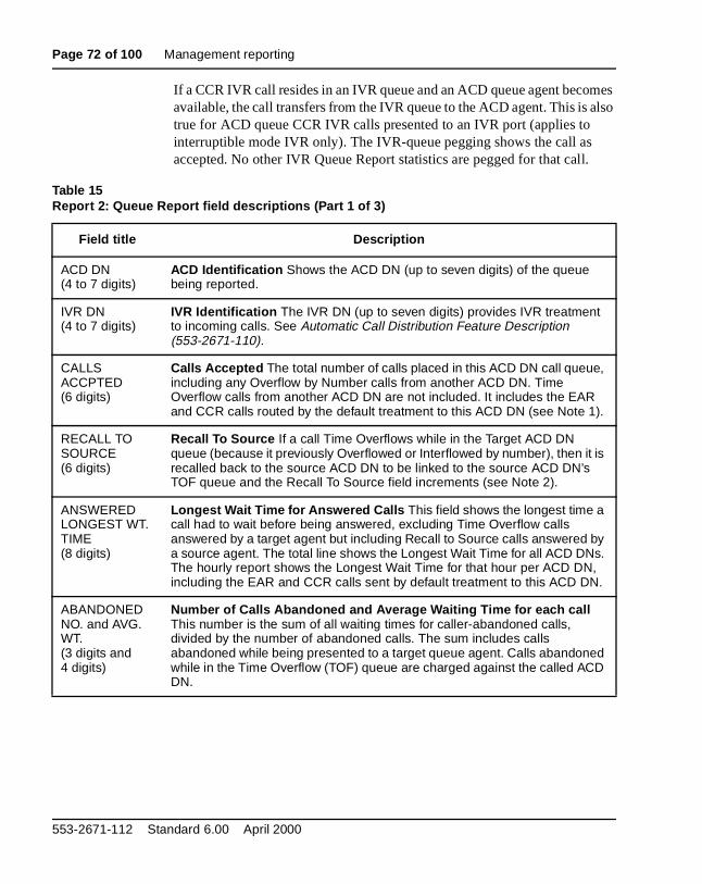
Page 3 of 100
se
nd
s
Revision historyApril 2000
Standard 6.00. This is a global document and is up-issued for X11 Relea25.0x.
June 1999Standard 5.00. This document is reissued for X11 Release 24.2x.
August 1996Standard 4.00. This document is reissued for X11 Release 22.0x.
December 1995Standard 3.00. This document is reissued to include editorial changes.
December 1994Standard 2.00. This document is reissued to include editorial changes aindexing.
August 1993Standard 1.00. This document includes all information from and replacedocuments 553-2671-102 and 553-2671-103.
Automatic Call Distribution Management commands and reports
Automatic Call Distribution Management commands and reports
Page 8 of 100 Contents
553-2671-112 Standard 6.00 April 2000
Page 9 of 100
22
the
e, ting mer
ive
IntroductionReference list
The following are the references in this section:
• Automatic Call Distribution Feature Description (553-2671-110)
• X11 System Messages Guide (553-3001-411)
Automatic Call Distribution (ACD) distributes incoming calls to agent positions in the same ACD queue.
The ACD Load Management system lets customers adjust the ACD configuration to respond to changing traffic loads. The supervisor’s digitdisplay and the printed ACD Management Reports provide insights into load situation.
Document overviewThis document describes the ACD load management commands that supervisors can use to tailor the system to meet changing needs.
This document also describes the optional Management Report packaglisting available management reports and providing the inputs for requesreports. The ACD Management Reports feature provides the ACD custowith timely and accurate statistics relevant to the ACD operation so the customer can monitor changing ACD traffic loads and implement correctaction when required.
Automatic Call Distribution Management commands and reports
Page 10 of 100 Introduction
al .
s)
ents
Operational overviewEach ACD customer can designate one supervisor position as a Senior Supervisor equipped with a Teletypewriter (TTY) or Video Display Termin(VDT) for Management Report functions or ACD Management functions
With the TTY or VDT, the senior supervisor can do the following:
— reassign auto-terminating ACD trunk routes
— reassign ACD agent positions to other ACD Directory Numbers (DN
— redefine the ACD Night Forwarding number
— reassign an ACD agent position to another supervisor
— assign priority or nonpriority status to ACD trunks
— set the timers and routes for first and second Recorded Announcem(RAN)
— specify a Night RAN route
— set the Target answer time T used to calculate the Telephone Service Factor (TSF)
— define the target queues for Automatic Overflow
— define the Overflow thresholds
— define the Interflow digits
— allow 1200 agent positions per ACD DN on NT and XT machines
— query the existing values for any of the above
Other documentationFor a complete description of the ACD system and features, refer to theAutomatic Call Distribution Feature Description (553-2671-110). For overlay and system message information, including error codes, refer to X11 System Messages Guide (553-3001-411).
553-2671-112 Standard 6.00 April 2000
Introduction Page 11 of 100
isor
ge
rints
Accessing the command modeBefore issuing load management or report commands, the senior supervmust enter command mode by following these steps.
1 Type $L from the senior supervisor’s display.
The system responds with a prompt (>) indicating that it is ready to receive further commands.
2 Enter new data on the same line as the prompt, and press the carriareturn key.
3 To query existing values, enter an ACD Management command.
4 Input new data if desired, or press the carriage return if no change isnecessary.
If there are any changes in a line, all data must be retyped.
5 To exit the ACD Management command mode, use the $ L.
With the proper VDT or TTY equipment, any supervisor can enter the ACDManagement command mode to view existing parameters. The system pthe values but does not display the prompt or allow further input.
Automatic Call Distribution Management commands and reports
Page 12 of 100 Introduction
rt
e wed
ich :
Management reporting commandsIf the ACD has the ACD Management Reports feature, any current repodisplay aborts when the $L command is entered.
After the senior supervisor inputs a management reporting command, thsystem prints the current parameters associated with the command, folloby a double dash to indicate that the system is ready for input.
Selecting print optionsThe Select Print (SPRT) command lets the senior supervisor specify whmanagement reports to print. The format for this command is as follows
SPRT vwxy VWXY
where:
v, w, x, and y are the reports to be printed:
1 for the Agent Group Report
2 for the Queue Report
3 for the Trunk Routes Report
4 for the Agent Position Report
553-2671-112 Standard 6.00 April 2000
Introduction Page 13 of 100
a
Scheduling periodic reportsThe Select Schedule (SSCH) command lets the senior supervisor defineschedule for periodic Management Reports. (LD 23 also permits report scheduling.) The format for the command is as follows:
SSCH sd sm ed em SD SM ED EMsh eh s SH EH Sd d d d d d d d D D D D D D D
where:
sd = the starting day (1–31)ed = the ending day (1–31)sm = the starting month (1–12)em = the ending month (1–12)sh = the starting hour (0–23)eh = the ending hour (0–23)s = the schedule code
d = Days of the week when reports are to be printed:
0 No reports are printed.
1 Reports are printed hourly on the hour.
2 Reports are printed every hour on the half-hour.
3 Reports are printed every half-hour.
4 Report 3 is printed every quarter-hour. No other reports areprinted.
5 Report 3 is printed every quarter-hour. Other reports can beprinted hourly on the hour.
6 Report 3 is printed every quarter-hour. Other reports can beprinted hourly on the half-hour.
7 Report 3 is printed every quarter-hour. Other reports can beprinted every half-hour.
1 = Sunday 5 = Thursday
2 = Monday 6 = Friday
3 = Tuesday 7 = Saturday
4 = Wednesday
Automatic Call Distribution Management commands and reports
Page 14 of 100 Introduction
in or s
T to
.
nd
he d
riod.
Report ControlThe ACD Report Control feature allows every ACD DN or control DN (CDN) to control report generation, including reports generated on the Meridian 1 (ACD-C) or by an auxiliary processor (ACD-D or ACD-MAX).Report Control only works with Meridian Mail SP8.
This feature eliminates the Virtual Agent Compatibility feature, introducedX11 Release 12, which did not allow the messages to be sent to ACD-DACD-MAX systems for virtual ACD DNs. The following three applicationuse Virtual Agent ACD groups:
— Integrated Voice Messaging System (IVMS)
— Data Services
— Meridian Mail
During conversion to X11 Release 17 from any earlier Release, set RPRNO for the above ACD DNs. Virtual agent reporting is unavailable on ACD-D or ACD-MAX before X11 Release 4.
This option includes Package C reports, ACD-D reports, and ACD-MAXFor a complete discussion of ACD-D and ACD-MAX reporting, see the associated documents listed earlier in this section.
An example: Reports 1, 2, 4, and Daily Totals show 10 ACD DNs. If twoACD DNs have RPRT = NO, then the total ACD DNs in Reports 1, 2, 4, aDaily Total shows 8 ACD DNs instead of 10 ACD DNs.
Operating parametersWhen making the decision to turn reporting on or off, take into account tinteractions among ACD DNs and CDNs through call redirection and loamanagement. Do not switch the reporting control on and off, as toggling between options generates inaccurate report information. If you need to change the report status, change the option at the end of a reporting pe
553-2671-112 Standard 6.00 April 2000
Introduction Page 15 of 100
n
e
ny eue,
Management command conventions
— With DN Expansion (DNXP) equipped, ACD DNs can be up to sevedigits.
— ACD Position ID (POS ID) identifies an agent position.
— Access code (ACOD) and member number (MEM) identify trunk number routes.
— Queues are identified by ACD DN.
— When a CDN is specified for any of the management commands, thsystem outputs “** CDN **”.
Enhanced ACD Routing (EAR)Enhanced ACD Routing (EAR) lets the system treat different calls differently, as described in Automatic Call Distribution Feature Description (553-2671-110).
A Control DN (CDN) is a special Directory Number not associated with aphysical telephone or equipment that specifies a destination ACD DN towhich incoming calls are directed. Multiple CDNs can place calls into thesame ACD queue. The parameters of the CDN, not those of the ACD qudetermine call treatment.
The following ACD Management commands are used for CDN default operation:
— FRRT First RAN route
— FRTT First RAN route time
— SRRT Second RAN route
— SRTO Second RAN route time option
Automatic Call Distribution Management commands and reports
Page 16 of 100 Introduction
new ore
s a
n
r
r
The following commands are supported for a CDN:
A new set of commands are added to support the CDNs on the system. Aprint command is Print CDN Parameters and Options (PCPO). The newparameters for the PCPO command are listed below and are covered mthoroughly in the PCPO section.
When the senior supervisor enters the above commands for a CDN, thesystem appends the term “** CDN **” to the command to tag the entry aCDN.
For example,
FRRT 8976
appears as
FRRT 8976 ** CDN **
— SRTA Select Route and Trunk Assignment. This is used to assigthe terminating ACD DN for an auto-terminating ACD trunk. A CDN can be used as a valid auto-terminating ACD DN.
— IFDN Interflow DN assignment. A CDN can be used as a valid Interflow DN of an ACD DN, but the CDN itself cannot have an Interflow DN.
— NITE Night Forwarding number assignment. A CDN can be used as a valid Night Call Forward DN of an ACD DN, butthe CDN itself cannot have a Night Call Forward DN.
— DTOT Daily Totals. This presents a Daily Totals Report for CDNs based on a schedule block and not on a per CDN oACD DN basis.
— STOT System Totals. This presents a System Totals Report forCDNs based on a schedule block and not on a per CDN oACD DN basis.
— DFDN Local default ACD DN for the CDN
— CEIL Call ceiling value for the CDN
553-2671-112 Standard 6.00 April 2000
Introduction Page 17 of 100
the . de the r to on.
Customer Controlled Routing (CCR)Customer Controlled Routing (CCR) enables the customer to customizetreatment and routing of incoming calls through a user-friendly interfaceUnder normal circumstances, calls arriving at a CDN in the controlled mohave their handling determined by a customer-defined script executed byCCRM application, rather than being handled by the X11 software. Refethe documents listed at the beginning of this section for further informati
The following ACD Management commands are supported if CCR is equipped and the CCRM application is controlling the CDN:
— TLDA Calls Waiting threshold (CWTH)
— TLDB Busy threshold (BYTH)
— TLDC Overflow threshold (OVTH)
— TSFT Telephone Service Factor (This allows the supervisor to change the threshold for calculating the TSF for the CDN.)
— CNTL Set Controlled mode
Automatic Call Distribution Management commands and reports
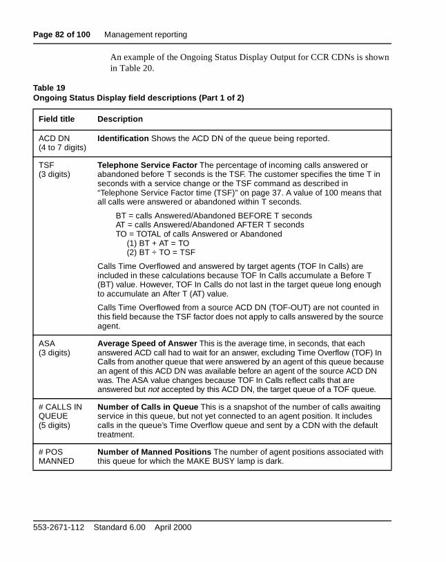
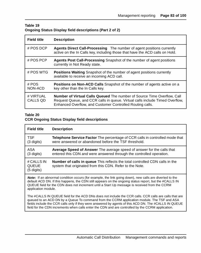
Report 1: Agent Group Report In the ACD-DN report for Report 1, the fields CALLS ANSWD and ASA are affected by the CCR feature only if thCCR calls are answered in the ACD queues, and the queues are respononly for the time the calls spent in the queues.
Report 2: Queue Report Calls placed in more than one ACD queue to awaan available agent are pegged against the ACD DN in which the call is answered. The wait time includes the time the call waited in the reportinACD DN, not the accumulated time spent in all queues. For a CDN in Rep2, only three fields are used: CALLS ACCEPT, BUSY, and DEFAULT D
Reports for ACD DNs — Multiple-queued calls do not affect the ACD queues’ statistics unless the calls were answered in the queues. The two fieladded to the Queue Report for CCR are ROUTE TO and DISC.
Reports for CDNs — All fields described for CDNs apply to CCR.
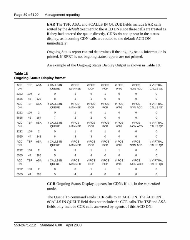
Ongoing Status Display If the EAR feature has been implemented, CDNs anot included in the Ongoing Status Display. All calls coming into the CDNroute to the default ACD DN immediately. If the CCR feature is used, the Ongoing Status Display reports both ACD DNs and CDNs for the customeCDNs have values in the TSF, ASA, and # CALLS IN QUEUE fields. All othfields contain asterisks indicating they do not apply to the CDN.
Agent ID optionThis feature provides the ACD customer with the option of operating in eitan Agent ID mode or a Position ID mode. If the Agent ID option is selectACD agents must enter a four-digit Agent ID code (range 0001 to 9999)before access is allowed to ACD features. This is part of the ACD telephlogin procedure that must be performed before access to ACD features allowed. Statistical performance data continues to be accumulated on aPosition ID basis. However, the Agent ID code of the agent who used thparticular agent position is reflected in the management reports.
553-2671-112 Standard 6.00 April 2000
Introduction Page 19 of 100
an one.
ent he
t,
e
in
and plus nt
e
not
ACD set loginAn agent’s or supervisor’s telephone cannot receive any ACD calls untilagent logs in to that telephone by pressing the In Calls key on the telephThe system ignores the key if no headset or handset is connected.
— If the Agent-ID option is not defined, the LED associated with the NOT-READY key LED illuminates and the telephone digit display shows the ACD DN and supervisor position. The telephone is accumulating time and the agent can access all ACD features.
— A special dial tone appears if the Agent-ID option is defined. The agmust key in the four-digit Agent-ID code on the telephone dial pad. Tsystem validates the digits and returns one of the following tones:
• Overflow tone if the code is not input before normal digit timeouor the code is invalid or out of range.
• Busy tone if another individual is already logged in with the samAgent-ID code.
A valid code gives the agent access to ACD features.
Note: The configuration record specifies the maximum number of agents who can be logged in to the system at any one time (promptMAGT in LD 17). An agent who exceeds this threshold by trying to logwill receive an overflow tone.
500/2500 telephone login protocolsSince the 500/2500 telephones do not have key lamps, the agent logs injoins the idle agent queue by going off hook and entering the SPRE code97. The agent can also login by entering the SPRE code plus 97 and thefour-digit Agent ID number, and then by going off hook. To logout, the agereenters the SPRE code plus 97, and goes on hook.
A special logged-in tone lets the agent know when the telephone is in thagent queue. Before logging in and after logging out the agent hears thenormal dial tone.
The login and logout commands clear the Not Ready mode. If the agent islogged in, the Not Ready mode cannot be activated.
Automatic Call Distribution Management commands and reports
Page 20 of 100 Introduction
M) ust
r on
in to sing
who this less
en
s
M) ust
Data Agent loginData Agents can press the Make Set Busy (MSB) key to login after ascertaining that the Data Shift key is lit on the Add-on Data Module (ADassociated with that agent position. The correct Class of Service (COS) mbe defined for this feature in LD 11.
ACD telephone logoutBefore logging out, the agent should check to see if any calls are active ohold (see “Walkaway/Return” on page 21).
Removing the headset/handset from a telephone that is currently loggedthe ACD operation terminates access for agents who have the option of uheadset/handset removals or activating the Make Set Busy key. Agentsdo not have this option can log out using the Make Set Busy key, unlesskey is unavailable. Pressing Make Set Busy causes immediate logout unthere is an active call on the In Call key, in which case logout occurs whthe call is disconnected.
After an agent logs out,
— The agent position is removed from the ACD agent queue.
— Beginning with X11 Release 19 for ACD packages C and D, systemwith a display show a “LOGGED OUT” message if the Make Set Busykey has been deactivated.
— All timing for that position stops.
Data Agent logoutData Agents can press the Make Set Busy (MSB) key to logout after ascertaining that the Data Shift key is lit on the Add-on Data Module (ADassociated with that agent position. The correct Class of Service (COS) mbe defined for this feature in LD 11.
553-2671-112 Standard 6.00 April 2000
Introduction Page 21 of 100
cts
ted
lls
gent val
as
way.
N the P
ormal
Walkaway/ReturnAn agent who is logged in can briefly leave the position, then return andresume normal operation without logging in again. (If the agent disconneby merely unplugging the headset or handset from the telephone, the Walkway/Return feature is not activated.)
Removing the headset/handset under any condition other than those lishere logs out the agent. These are the Walkaway procedures:
— Direct Call-Processing (DCP) phase (In Calls LED lit) During this operation, the agent is connected with a caller. Before removing theheadset/handset, the agent presses the Hold key, causing the In CaLED to flash at 120 ipm and initiating Walkaway.
— Post Call-Processing (PCP) phase (NOT READY LED lit) During this operation, the agent and the caller are disconnected. When the apresses the Hold key, the Not Ready LED flashes at 120 ipm. Remoof the headset/handset initiates Walkaway.
— Non-ACD call-handling phase (DN LED lit) A non-ACD call is connected to the agent position. The agent presses the Hold key to keep the call connection, and the DN LED flashes at 120 ipm, permitting Walkaway.
Timing continues during Walkaway, accumulating in the category that wactive before Walkaway.
If the supervisor has corresponding agent keys, they flash 120 ipm for Walka
— No lamp for MSB
— Steady lamp for Busy on In-Calls
— Slow flash for waiting for a call
— Fast flash for DN calls
Note: If the incoming caller disconnects from an on hold In Calls or Dkey, the telephone reverts automatically to the Not Ready state andNot Ready LED flashes. The timing for the prior state stops, and PCtiming starts.
When an agent or supervisor returns to an agent position that is in the Walkaway mode and plugs the headset/handset into the telephone, the noperation of ACD features resumes.
Automatic Call Distribution Management commands and reports
Page 22 of 100 Introduction
s a nd ueue the
calls
er call
the
the
Agents using DN keysActivating any DN key lights the associated LED indicator lamp and givedial tone. An incoming call to that DN causes the LED indicator to flash athe agent telephone to ring. This assumes that any and all agents on a qbasis are permitted to use DN keys, or the agent is already logged in. If agent is not permitted to use DN keys when not logged in, the LED for incoming DN calls flashes. However, the agent is not able to answer the until logged in to the queue.
Alternate Call AnswerThe Alternate Call Answer feature allows the customer to choose, on a pqueue basis, if ACD calls should be blocked for an agent set with an IDN on hold. For complete information, see Automatic Call Distribution Feature Description (553-2671-110).
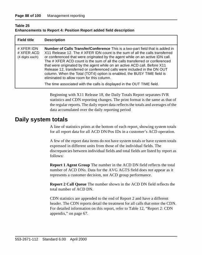
In Report 1, if an agent answers an ACD call while an IDN call is on hold, time for the ACD call shows as AVG DCP instead of AVG TIME.
In Report 4, if an agent answers an ACD call while an IDN call is on hold, time for the ACD call shows as AVG DCP instead of INC TIME or OUT TIME.
553-2671-112 Standard 6.00 April 2000
Page 23 of 100
44
ute to d
nd s in
ied
N
Load management commandsReference list
The following are the references in this section:
• Automatic Call Distribution Feature Description (553-2671-110)
This section describes the commands that a senior supervisor can execmanage and manipulate system traffic. Refer to “Accessing the commanmode” on page 11 for information on using the command system.
Set Controlled mode (CNTL)The CNTL command operates only if CCR is equipped. The CNTL commadetermines if the selected CDN is in controlled mode. The CDN operatethe controlled mode when the value is ON.
The command format is as follows:
An error is output on the supervisor’s terminal when a non-CDN is speciffor the CDN field or a mode key word other than ON or OFF is given.
Note: For EAR, the CNTL option is always OFF; this restricts the CDto using default treatment for EAR only.
CNTL CDN -- <Existing mode > -- MODE
Legend:CDN = The Directory Number of the CDN
MODE = ON for controlled mode and OFF for default mode
Automatic Call Distribution Management commands and reports
Page 24 of 100 Load management commands
the ult
Set Default ACD DN (DFDN)The DFDN command sets the Default ACD DN for a CDN to operate in default mode. This DN is the primary target for CDN calls receiving defatreatment. This ACD DN must be local. The ACD DN defined for data service access cannot be used as a default ACD DN.
The command format is as follows:
DFDN CDN -- <Existing DFDN > -- ACD DN
Legend: DFDN CDN = Set the default ACD DN for this CDN
<Existing DFDN> = Output by the system, the current DFDN
ACD DN = The new default ACD DN to be entered
553-2671-112 Standard 6.00 April 2000
Load management commands Page 25 of 100
N
is
Query current options (POPT)The command POPT enables supervisors and the senior supervisor to determine the current options in effect for each ACD DN. For each ACD Dspecified, the following information is given:
The format for this command is as follows:
FRRT = First RAN Route Number
FRTT = First RAN Route Time
SRRT = Second RAN Route Number
SRTO = Second RAN Route Time
MURT = Music Route
FORC = Whether or not Call Forcing is in effect
FCFT = Flexible Call Force timer
OBTN = Whether or not Observation Tone is given to an agent when being observed by a supervisor
SPCP = Whether or not the Separate Post Call-Processing optionin effect
NRRT = Night RAN Route
NITE = Night Forwarding Number if defined
POPT xxxx xxxx .... xxxx
Legend:xxxx = an ACD DN up to seven digits. “ALL” can be entered
here to see the options applicable to all ACD DNs in the customer’s operation.
Automatic Call Distribution Management commands and reports
Page 26 of 100 Load management commands
ry the
Query current parameters (PPAR)The command PPAR enables the senior supervisor or supervisors to quecurrent parameters associated with each ACD DN. For each ACD DN specified, the following information is given:
The format for this command is as follows:
MAXP = Maximum number of Positions assigned
TSFT = Telephone Service Factor Time, in seconds
TLDA = Calls Waiting Threshold
TLDB = Busy Threshold
TLDC = Overflow Threshold
TLDD = Time Overflow Threshold
SQ01 = First Overflow Target queue
SQ02 = Second Overflow Target queue
SQ03 = Third Overflow Target queue
IFDN = Interflow number
PPAR xxxx xxxx .... xxxx
Legend:xxxx = an ACD DN up to seven digits. “ALL” can be input to see
the values in effect for all ACD DNs in the customer’s operation.
553-2671-112 Standard 6.00 April 2000
Load management commands Page 27 of 100
t
Select Route and Trunk Assignment (SRTA)The Select Route and Trunk Assignment (SRTA) command assigns theterminating ACD DN for an auto-terminating ACD trunk. A CDN can be used as a valid auto-terminating ACD DN.
Changing the terminating ACD DN for a trunk affects only those calls thaseize the trunk after the ACD DN is changed. The input format for this command is as follows:
Select trunk Priority Assignment (SPRI)The senior supervisor can assign individual ACD trunks to priority or nonpriority status with the following command:
Note: 0 equals no priority; 1 equals priority.
SRTA RAC MEM xxxx XXXX
Legend:RAC = Route Access Code (up to seven digits with DNXP)
MEM = Trunk Member number (1–126)
xxxx = current ACD DN/CDN where the trunk is assigned
XXXX = new ACD DN/CDN (up to seven digits with DNXP)
SPRI RAC MEM x X
Legend:RAC = Trunk Route Access Code
MEM = Trunk Route Member number (1–126)
x = Current priority assignment (0 or 1)
X = New priority assignment (0 or 1)
Automatic Call Distribution Management commands and reports
Page 28 of 100 Load management commands
tive.
in
only
ot
ckage me d
es
Select Agent Position Assignment (SAPA)The Select Agent Position Assignment (SAPA) command changes an individual agent’s ACD DN queue assignment. The agent must enter theMake Set Busy (MSB) mode before the new assignment becomes effec
The transfer will not occur (an error message is output) if there is no roomthe ACD position list at the time of execution.
More than one SAPA command can be outstanding at any one time, but the final command is effective.
The format for this command is as follows:
Note 1: Supervisors within the ACD Package D environment must nconfuse Virtual Agent position functions with Actual Agent position operations. Please refer to the ACD-D documents for details.
Note 2: With ACD Package D the agent does not have to be in MSBmode to be assigned to another queue as the agent does for ACD PaC. If the ACD Package D agent has a ringing call coming from the TiOverflow (TOF) queue while being moved, that ringing call is returneto the front of the TOF queue where it originated.
Note 3: When Report Control is active, it is possible that agent movwill not be reported for one or another queue. Refer to Automatic Call Distribution Feature Description (553-2671-110) for a complete discussion.
SAPA XXXX yyyy YYYY
Legend:XXXX = Applicable Agent Position-ID
yyyy = The ACD DN to which the position is currently assigned
YYYY = The new ACD DN assignment
553-2671-112 Standard 6.00 April 2000
Load management commands Page 29 of 100
e ne nt CDN
r.
an
Select Agent to Supervisor Assignment (SATS)The Select Agent to Supervisor Assignment command (SATS) allows thsenior supervisor to reassign an agent position from the Agent key on osupervisor position to an Agent key on another supervisor position. Agekeys are assigned through the LD 11. This command cannot operate on queues.
The format for this command is as follows:
Note 1: Specifying X for the new supervisor Position ID removes theagent from the current supervisor without assigning a new superviso
Note 2: A supervisor who lacks telephone Agent keys must press acarriage return instead of a key number when using SATS to assignagent to a supervisor.
SATS XXXX yyyy zz YYYY ZZ
Legend:XXXX = Position ID for the agent to be reassigned
yyyy = The supervisor Position ID where the agent position is currently assigned
zz = The Agent key on the supervisor’s telephone where the agent position is currently assigned
YYYY = The new supervisor Position ID (see Note 1)
ZZ = The Agent key on the new supervisor’s telephone
Automatic Call Distribution Management commands and reports
Page 30 of 100 Load management commands
CD
rst
First RAN Route Assignment (FRRT)The First RAN Route Assignment (FRRT) command specifies (for each ADN) the trunk route access code for the first Recorded Announcement (RAN). If a CDN is the command target, “**CDN**” appears on the command line. For example, if 8976 is a CDN, “FRRT 8976 **CDN**” appears.
The format for this command is as follows:
Note: Specifying X for the new RAN route access code removes the fiRAN feature from the ACD DN.
FRRT XXXX yyyy YYYY
Legend:XXXX = Applicable ACD DN/CDN up to seven digits with DNXP.
If EAR is equipped, then XXXX can be a CDN.
yyyy = Current first RAN route access code
YYYY = New first RAN route access code of up to four digits
553-2671-112 Standard 6.00 April 2000
Load management commands Page 31 of 100
ing e
nk the .
he
First RAN Route Time (FRTT)The First RAN Route Time (FRTT) indicates how many seconds an incomACD call can remain unanswered before receiving first RAN. If a CDN isspecified as the command target, the command outputs “**CDN**” on thcommand line. For example, if 8976 is a CDN, “FRTT 8976 **CDN**” appears.
The format for this command is as follows:
Second RAN Route Assignment (SRRT)The Second RAN Route Assignment (SRRT) command specifies the truroute access code for the second RAN for each ACD DN. If the target ofcommand is a CDN, the output “**CDN**” appears on the command lineFor example, if 8976 is a CDN, “SRRT 8976 **CDN**” appears.
The format for this command is as follows:
Note: Specifying X for the second RAN route access code removes tsecond RAN feature from the ACD DN.
FRTT XXXX yyyy YYYY
Legend:XXXX = Applicable ACD DN/CDN (up to seven digits with
DNXP). If EAR is equipped, then XXXX can be a CDN.
yyyy = Current first RAN time
YYYY = New first RAN time in seconds (0–2044)
SRRT XXXX yyyy YYYY
Legend:
XXXX = Applicable ACD DN/CDN up to seven digits with DNXP. If EAR is equipped, then XXXX can be a CDN.
yyyy = Current second RAN route access code
YYYY = New second RAN route access code (see Note)
Automatic Call Distribution Management commands and reports
Page 32 of 100 Load management commands
any arget le,
Second RAN Route Time Option (SRTO)The Second RAN Route Time Option (SRTO) command indicates how mseconds should elapse between first and second RAN. If the command tis a CDN, the output “**CDN**” appears on the command line. For exampif 8976 is a CDN, “SRTO 8976 **CDN**” appears.
The command format is as follows:
Night RAN Route Assignment (NRRT)The Night RAN Route Assignment (NRRT) command specifies the trunkroute access code for the night RAN.
The format for this command is as follows:
Note: Specifying X for the Night RAN access code disables Night Forwarding for the ACD DN.
SRTO XXXX yyyy YYYY
Legend:XXXX = Applicable ACD DN/CDN up to seven digits with
DNXP. If EAR is equipped, then XXXX can be a CDN.
yyyy = Current Second RAN time
YYYY = New second RAN time in seconds (0–2044)
NRRT XXXX yyyy YYYY
Legend:XXXX = Applicable ACD DN up to seven digits
yyyy = Current night RAN access code
YYYY = New night RAN access code up to four digits (see Note)
553-2671-112 Standard 6.00 April 2000
Load management commands Page 33 of 100
use he
he or
Night Forwarding number assignment (NITE)The NITE command designates a forwarding number, up to 23 digits, towhen the ACD is in Night Service or when all ACD telephones are in theMake Set Busy mode. A CDN cannot have Night Service; it defaults to tdefault ACD DN.
The command format is as follows:
If EAR is equipped, use the following:
Note 1: Specifying X for the Night Forward number disables Night Forwarding for the ACD DN.
Note 2: The ASA field is upgraded when the next report is updated. TASA field is not updated when the ACD queue goes into night serviceduring the 30-second display of ongoing status.
NITE XXXX yyy ... y YYY ... Y
Legend:XXXX = Applicable ACD DN (up to seven digits with DNXP)
yyy ... y = Current Night Forward number
YYY ... Y
= The new Night Forward number up to 23 digits including the asterisk (*) to indicate dialing pause where required
XXXX = Applicable ACD DN; it cannot be a CDN
yyy...y = It can be a CDN
YYY...Y = It can be a CDN
Automatic Call Distribution Management commands and reports
Page 34 of 100 Load management commands
or
Automatic Overflow Target DN (SQ01, SQ02, SQ03)The following commands define or change up to three target ACD DNs fthe Automatic Overflow feature. The formats of the commands are as follows:
SQ01 WWWW xxxx XXXX
SQ02 WWWW yyyy YYYY
SQ03 WWWW zzzz ZZZZ
Note: Specifying X for a new target ACD DN deletes it, replacing it with the next choice, if applicable. For instance, if X is specified for the target ACD DN for SQ02, the target ACD DN specified for SQ03 becomes the SQ02 target ACD DN.
Legend:WWWW
= ACD DN for the Source queue up to seven digits
xxxx = Current first Target ACD DN
XXXX = New first Target ACD DN
yyyy = Current second Target ACD DN
YYYY = New second Target ACD DN
zzzz = Current third Target ACD DN
ZZZZ = New third Target ACD DN
553-2671-112 Standard 6.00 April 2000
Load management commands Page 35 of 100
1,
0, N.
to ut
is
Automatic Overflow thresholds (TLDA, TLDB, TLDC)The TLDA, TLDB, and TLDC commands allow adjustments to Calls Waiting (CWTH), Busy (BYTH), and Overflow (OVTH) thresholds, respectively.
— Specifying X as the new threshold for TLDA reduces the threshold tothus the Calls Waiting lamp lights when any call is waiting.
— Specifying X as the new threshold for TLDB reduces the threshold topreventing acceptance of any calls overflowed from another ACD D
— Specifying X as the new threshold for TLDC increases the threshold its maximum value (2047) and prevents any calls from overflowing oof the ACD DN.
— If CCR is equipped and the CDN is in the controlled mode, the CDNalso supported by the TLDA, TLDB, and TLDC commands.
The Overflow threshold command formats are as follows:
TLDA XXXX yyyy YYYY
TLDB XXXX yyyy YYYY
TLDC XXXX yyyy YYYY
Legend:XXXX = Applicable ACD DN (up to seven digits with DNXP)
yyyy = Current threshold value
YYYY = New threshold value (0–2047)
Automatic Call Distribution Management commands and reports
Page 36 of 100 Load management commands
ime
e 18
sage
r Ns
Time Overflow threshold (TLDD)The TLDD command allows the supervisor to set, change, or clear the TOverflow Timer (TOFT, introduced in X11 Release 10) for an ACD DN.
The Time Overflow threshold command format is as follows:
TLDD XXXX NONE YYYY (the TOFT value can be 10–1800 seconds before X11 Release 18 or 2–1800 seconds with X11 Releasand later)
TLDD XXXX yyyy YYYY (change TOFT value)
TLDD XXXX YYYY X (delete TOFT value)
After the Time Overflow Timer (TOFT) has been defined, the target ACDDNs of this ACD DN can answer ACD DN calls. If one of the target ACDDNs is already answering the maximum six source queues, an error mesappears showing the affected target ACD DN (ACD103). The supervisomust remove the affected target ACD DN from one of the source ACD Dbefore defining the TLDD value.
Legend:XXXX = ACD DN
NONE = TOFT is undefined; calls do not overflow for this DN
yyyy = Current threshold timer
YYYY = New threshold timer
553-2671-112 Standard 6.00 April 2000
Load management commands Page 37 of 100
ws:
ed
Setting the Interflow DN (IFDN)This command indicates, for each ACD DN, the destination DN for ACDcalls when the Interflow feature is active. The command format is as follo
If equipped with EAR, use the following:
Note: Specifying X for the new Interflow DN disables the Interflow feature for the ACD DN even though an Interflow key might be assignto a supervisor position.
Telephone Service Factor time (TSF)This command sets or changes the value of T (in seconds) for the TelephoneService Factor (TSF). The command format is as follows:
IFDN XXXX yyy ... y YYY ... Y
Legend:XXXX = Applicable ACD DN, up to seven digits if DNXP
yyy ... y = Current Interflow DN/ACD can be any Interflow DN
YYY ... Y
= New Interflow DN up to 23 digits including the asterisk (*) to indicate a dialing pause (see Note)
XXXX = Applicable ACD DN; it cannot be a CDN
yyyy and YYYY = Can be a CDN
TSFT XXXX yyy YYY
Legend:XXXX = Applicable ACD DN up to four digits (seven if DN
expansion is equipped)
yyy = Current value of T
YYY = New value of T in seconds (1–510)
Automatic Call Distribution Management commands and reports
Page 38 of 100 Load management commands
ty
iority
nd
rmat
he
Set Agent Priority (SAGP)The Priority Agent feature allows ACD agents to handle calls based on system-defined priorities for each ACD DN or ACD DN group. The PrioriAgents package (116) must be implemented.
The SAGP command allows the manager to set and change an agent’s prto receive calls based on the Agent’s Position ID (POS-ID).
If the Agent’s POS-ID is not defined, an error code appears. The commaformat is as follows:
Note: The range for Agent Priorities is 1–48 for NT, XT, or System options 51, 51C, 61, 61C, or 71, 81, and 81C, and 1–32 for all othermachine types.
List Agent Position Assignment (LAPA)This command changes the ACD DN for up to 10 agents at a time. The foto assign the ACD DNs is as follows:
Note: The LAPA and LAGP commands can only be executed with tACD-D package.
SAGP ZZZZ pp PP
Legend:ZZZZ = POS-ID
pp = Old Priority set
PP = New Priority set
LAPA XXXX yyyy yyyy yyyy. . . yyyy
Legend:XXXX = ACD DN; up to seven digits if DNXP
yyyy = agent position ID (limited to 10)
553-2671-112 Standard 6.00 April 2000
Load management commands Page 39 of 100
s.
and nge
1, pes.
he
List Agent Priority (LAGP)The Priority Agent feature allows ACD Agents to handle calls based on system-defined priorities by an individual ACD DN or a group of ACD DNThe Priority Agents package (package 116) must be implemented.
The LAGP (List Agent Priority) command defines Priority Agent Groups,allowing up to 10 agents in the same Priority Agent Group.
The LAGP command sets and changes a Priority Agent Group’s priority member list based on Position ID (POS-ID). The command format to chaa priority or group list is as follows:
Note 1: The range for Agent Priorities is 1–48 for NT, XT, 51, 51C, 661C, 71, 81, or 81C machine types, and 1–32 for all other machine ty
Note 2: The LAPA and LAGP commands can only be executed with tACD-D package.
LAGP pp XXXX XXXX XXXX . . . XXXX
Legend:pp = Priority for the Group
XXXX = Agent POS-IDs for group members (up to 10)
Automatic Call Distribution Management commands and reports
Page 40 of 100 Load management commands
s the ent
le
tly
ed
Enable Call Force (FORC)Call Force automatically connects a call with an idle agent and determinetime delay (default is 2 seconds) between call disconnection and placemin the idle agent queue. (See “Enable Flexible Call Force (FCFT)” on page 41.) ACD Package B must be installed and implemented.
The FORC command enables or disables the Call Force feature. To enab the Call Force feature, enter the following:
Note: If a carriage return is entered, the feature remains disabled.
To disable the Call Force feature, enter the following:
Note: If a carriage return is entered, the feature remains enabled.
FORC XXXXXXX no YES
Legend:XXXXXXX
= The applicable ACD DN (up to seven digits)
no = Output by the system meaning Call Force is currendisabled
YES = Input by the user to indicate enable Call Force
FORC XXXXXXX yes NO
Legend:XXXXXXX
= The applicable ACD DN (up to seven digits)
yes = Output by the system indicating Call Force is enabl
NO = Input by the user to disable Call Force
553-2671-112 Standard 6.00 April 2000
Load management commands Page 41 of 100
age
e.
Enable Flexible Call Force (FCFT)Beginning with X11 Release 16, Flexible Call Force allows a time delay 0–30 seconds. (See “Enable Call Force (FORC)” on page 40.) ACD PackB must be enabled to implement the FCFT command.
The FCFT command is as follows:
Note: If a carriage return is entered, the current time does not chang
FCFT XXXXXXX nn NN
Legend:XXXXXXX
= The applicable ACD DN (up to seven digits)
nn = Output by the system indicating the current delay time
NN = Input by the user to enter a new delay time
Automatic Call Distribution Management commands and reports
Page 42 of 100 Load management commands
DNs
1.
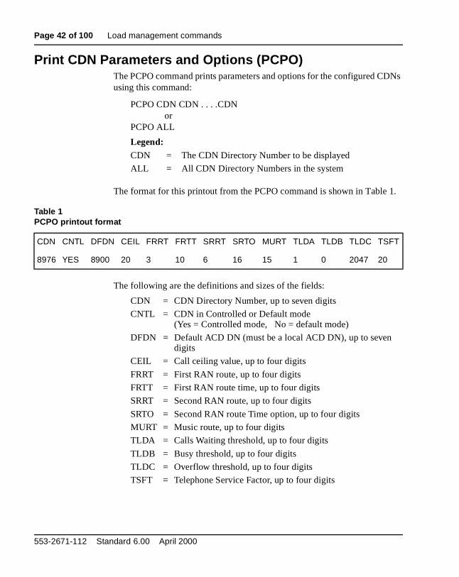
Print CDN Parameters and Options (PCPO)The PCPO command prints parameters and options for the configured Cusing this command:
PCPO CDN CDN . . . .CDNor
PCPO ALL
The format for this printout from the PCPO command is shown in Table
The following are the definitions and sizes of the fields:
Legend:CDN = The CDN Directory Number to be displayed
CNTL = CDN in Controlled or Default mode (Yes = Controlled mode, No = default mode)
DFDN = Default ACD DN (must be a local ACD DN), up to seven digits
CEIL = Call ceiling value, up to four digits
FRRT = First RAN route, up to four digits
FRTT = First RAN route time, up to four digits
SRRT = Second RAN route, up to four digits
SRTO = Second RAN route Time option, up to four digits
MURT = Music route, up to four digits
TLDA = Calls Waiting threshold, up to four digits
TLDB = Busy threshold, up to four digits
TLDC = Overflow threshold, up to four digits
TSFT = Telephone Service Factor, up to four digits
553-2671-112 Standard 6.00 April 2000
Load management commands Page 43 of 100
ing
Set the Call Ceiling (CEIL)The CEIL command sets the CDN call ceiling value.
The command format is as follows:
Display Routing Tables (DSPL)Use the DSPL command with Enhanced Overflow to review queue RoutTables.
The command format is as follows:
DSPL (ACD DN)
displays all queue Routing Tables in the ACD system, including the following information:
CEIL CDN -- <Existing Ceiling value> -- CV
Legend:CEIL CDN = Set the ceiling value for this CDN
<Existing Ceiling value>
= Output by the system, current call ceiling
CV = The new ceiling value to be entered (0–2047)
ACD DN ACD DN indicated by the DSPL command
Table Day or Night Enhanced Overflow Table (Table D or N)
Entry Entry number, from 1 to 20
Target ID Overflow DN
Timer Threshold value (in seconds) of this entry
Status Queue status, active or inactive (blank)
Registered Success of last queue request, OK or blank
Automatic Call Distribution Management commands and reports
Page 44 of 100 Load management commands
553-2671-112 Standard 6.00 April 2000
Page 45 of 100
94
ent ent,
o
A e d visor
ules
hour, ated n
Management reportingReference list
The following are the references in this section:
• Automatic Call Distribution Feature Description (553-2671-110)
ACD supervisors and senior supervisors can use the optional ManagemReporting package to receive four management reports that describe agqueue, and trunk activity. This section of the document describes those reports, their fields, and other management reporting options available tsupervisors.
Obtaining supervisor reportsAn ACD supervisor can view statistical data using a terminal or teletypewriter from an ACD supervisor position. The terminal must be EIRS-232-C compatible and support the standard ASCII character set. ThACD supervisor display reflects the status of ACD queues and is updateevery 30 or 60 seconds (specified through a service change). The supercan query schedules and printing options in addition to viewing the ACDinformation.
One senior supervisor position per customer has the ability to define andchange report printing schedules and options. The periodic report schedand options can also be defined through service change LD 23.
Periodic management reports can be scheduled for regular output on theon the half hour, or less frequently. As of X11 Release 3, report 3 is updevery 15 minutes. The four periodic management reports (REPT) contaistatistics accumulated since the previous printing.
Automatic Call Distribution Management commands and reports
Page 46 of 100 Management reporting
n
D orts
The
l ort
ble
has hen ged and
d
ed n
ered ort.
The four reports are as follows:
Before issuing report commands, see “Accessing the command mode” opage 11.
Report ControlReport control, available beginning with X11 Release 18, allows every ACDN or CDN to customize report generation. The decision to generate repoccurs at the system level, where the report option is set to ON or OFF.following features apply to report control.
Control Directory Numbers Control Directory Numbers (CDNs) are speciaDNs to be used with the Enhanced ACD Routing (EAR) feature. ACD RepControl applies to CDNs and ACD DNs. Reporting on CDNs is not availaon ACD-D or ACD-MAX until X11 Release 4.
Enhanced Overflow Both the source and the target DNs must have the option turned on for accurate reports. For example, the source ACD DNthe option turned off and the target ACD DN has the option turned on. Wa call overflows by count and is answered by the target DN, that call is pegfor the target DN but not for the source DN. For accurate reports, sourcetarget ACD DNs should both be on. To use Enhanced Overflow with ACD-MAX, NACD is required on MAX. It is not possible to use enhanceACD with ACD-D.
Network ACD When calling across a network, both the local and remoteACD DNs must have the option turned on for reports to be balanced.
Overflow by count The source and target DNs must have the option turnon for accurate reports. For example, the source ACD DN has the optioturned off and the target ACD DN has the option turned on. When an overflowed call is answered by the target DN, that call is pegged as answfor the target DN but not for the source DN, resulting in an inaccurate rep
— REPT 1 Agent Group Report
— REPT 2 Queue Report (CDN)
— REPT 3 Trunk Routes Report (RAN)
— REPT 4 Agent Position Report
553-2671-112 Standard 6.00 April 2000
Management reporting Page 47 of 100
n
e a
ged
or
.
,
art not yes
Report commands If the Daily Total report (DTOT) command or System Total report (STOT) commands are issued for a queue that has the optiodisabled, reports are not generated for these queues.
Time Overflow Both the source and the target DNs must have the optionturned on for accurate reports. For example, the source ACD DN has thoption turned off and the target ACD DN has the option turned on. WhenTime Overflowed (TOF) call is answered by the target DN, that call is pegas answered for the target DN but not for the source DN.
The Report Control feature affects the following reports:
— Report 1 (ACD DN report) When RPRT is yes for the specified ACDDN, this report is printed.
— Report 2 (ACD queue report) When RPRT is yes for the specified ACD queue, this report is printed. For CDN reporting, RPRT is yes fCDNs.
— Report 3 (trunk report) This report is not affected by the RPRT optionRPRT for CDN produces RAN reports for CDNs.
— Report 4 (Agent report) When RPRT is yes for the specified ACD DNany Agent activity, while belonging to this ACD DN, is printed.
— Daily Total report The RPRT option must be yes at the end of the reporting period for a report to be printed. If RPRT is set to yes for pof the reporting period but is turned to no for the rest of it, a report is printed. If the option is set to no for part of the period, then turned to at the end of the reporting period, a report for the full day is printed.
— Ongoing Status If RPRT is set to no, ongoing status reports are not printed.
Automatic Call Distribution Management commands and reports
Page 48 of 100 Management reporting
al le, . N.
CD the
rvice
e
re
— Short report The short report is affected by the RPRT option. Severconditions are possible for the report to print or not to print. For exampAgent 1 is logged on to ACD DN 5512, then moves to ACD DN 5579The report feature does not follow the agent, but is controlled by the DTable 2 shows a report example:
Warning messagesEach printed periodic report (Figures 3 through 9) contains a heading (Acustomer number, date, time) and warning messages (if any), followed byreports that have been specified. One or more of the following warning messages may appear after the report heading:
SCHED CHG (Schedule Change) This message prints if the periodic reporting schedule has been changed (by the senior supervisor or by sechange) since the last reporting period.
INIT (Initialize) This message prints if an initialization has occurred sincthe last reporting period. The periodic reports do not print because initialization erases all data. The accumulation areas are cleared to ensuaccurate statistics for the next reporting period.
Table 2Report Control Settings
ACD DN 5512 report control set to:
ACD DN 5579 report control set to:
Report printed for agent
YES YES YES
YES NO YES
NO YES YES
NO NO NO
553-2671-112 Standard 6.00 April 2000
Management reporting Page 49 of 100
e this rted G
nd
y
s
PER GT HR (Period Greater Than One Hour) This message prints if the time since the last reporting period exceeds one hour. For example, if threporting schedule is set from 0800 to 1600 daily, the 0800 report carrieswarning message. This message indicates that data in some of the repofields may be misleading. For example, the Average Agents Available (AVAGTS) field is calculated assuming a maximum interval of 60 minutes. Similarly, other fields that involve the elapsed time may have overflowed aare reported inaccurately. Three fields are affected as follows:
— AVG BUSY (Average Busy) The average time an agent position is buson a call.
— AVG MANNED (Average Manned) The average time an agent position is in Not Ready (NRD) state.
— INC CCS (Incoming Centi Call Seconds) The number of CCS (Centi Call Seconds) used. See Report 3, Trunk Routes.
Note: If the calculation of a field requires division and the resulting number is greater than five digits, four asterisks (****) print instead. This also occurs when the calculation requires division by zero. Fieldthat are not applicable for that category have dots in the line entry.
Automatic Call Distribution Management commands and reports
Page 50 of 100 Management reporting
field ute es 3
ount
the .
this ted.
tals
ter.
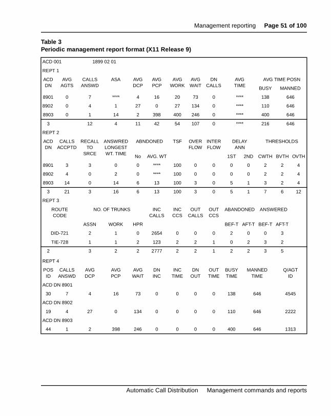
Report dataThis section includes sample management reports. These reports are examples only. Your actual reports will contain different data.
Tables 10 through 17 provide a description of the data contained in each of the Agent Group Report (REPT 1), Queue Report (REPT 2), Trunk RoReport (REPT 3), and Agent Position Report (REPT 4), as shown in Figurthrough 9.
Data shown in the Calls Accepted field is based on the following:
— If a call is night forwarded, it is counted in the interflow field for the source ACD DN in the queue report.
— If the night forwarded number is an ACD DN, then calls accepted, answered, and abandoned, among other things, are reflected in the cfor the terminating ACD DN. The call is not counted as call accepted against the source ACD DN.
— If a call is not night forwarded (whether or not night RAN is given), itcounts as a call accepted or answered, among other things, againstsource ACD DN. It will not count under the interflow field in this case
— If the Time Overflow (TOF)
feature is used, the calls accepted value
includes answered time overflow calls from another queue. Calls to ACD DN that another queue answers (by time overflow) are not coun
IVR queues are reported separately in Reports 1, 2, 4, and the Daily ToReport. The IVR reports do not balance as other reports do.
Fields that are not applicable for a category have dots in the line entry.
If a report is wider than 80 columns, it truncates on an 80-character prinReports wrap around on printers that can autowrap.
The following tables show what typical reports look like. These show averages. A Total option shows totals instead of averages.
553-2671-112 Standard 6.00 April 2000
Management reporting Page 51 of 100
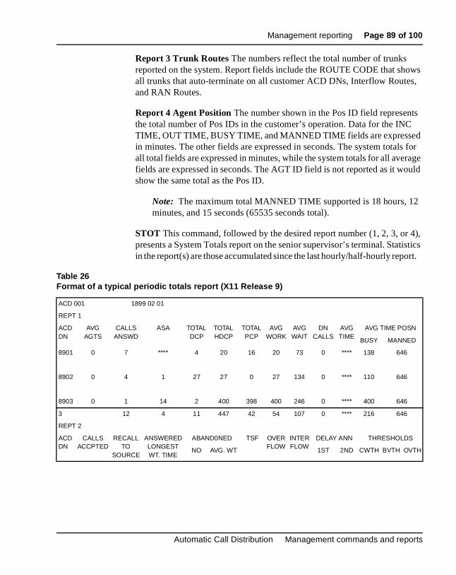
Table 3Periodic management report format (X11 Release 9)
ACD 001 1899 02 01
REPT 1
ACD DN
AVG AGTS
CALLS ANSWD
ASA AVGDCP
AVG PCP
AVG WORK
AVG WAIT
DN CALLS
AVG TIME
AVG TIME POSN
BUSY MANNED
8901 0 7 **** 4 16 20 73 0 **** 138 646
8902 0 4 1 27 0 27 134 0 **** 110 646
8903 0 1 14 2 398 400 246 0 **** 400 646
3 12 4 11 42 54 107 0 **** 216 646
REPT 2
ACDDN
CALLS ACCPTD
RECALL TO
SRCE
ANSWRED LONGEST WT. TIME
ABNDONED TSF OVERFLOW
INTERFLOW
DELAY ANN
THRESHOLDS
No AVG. WT 1ST 2ND CWTH BVTH OVTH
8901 3 3 0 0 **** 100 0 0 0 0 2 2 4
8902 4 0 2 0 **** 100 0 0 0 0 2 2 4
8903 14 0 14 6 13 100 3 0 5 1 3 2 4
3 21 3 16 6 13 100 3 0 5 1 7 6 12
REPT 3
ROUTE CODE
NO. OF TRUNKS
INC CALLS
INC CCS
OUT CALLS
OUT CCS
ABANDONED ANSWERED
ASSN WORK HPR BEF-T AFT-T BEF-T AFT-T
DID-721 2 1 0 2654 0 0 0 2 0 0 3
TIE-728 1 1 2 123 2 2 1 0 2 3 2
2 3 2 2 2777 2 2 1 2 2 3 5
REPT 4
POS ID
CALLS ANSWD
AVG DCP
AVG PCP
AVG WAIT
DN INC
INC TIME
DN OUT
OUT TIME
BUSY TIME
MANNED TIME
Q/AGT ID
ACD DN 8901
30 7 4 16 73 0 0 0 0 138 646 4545
ACD DN 8902
19 4 27 0 134 0 0 0 0 110 646 2222
ACD DN 8903
44 1 2 398 246 0 0 0 0 400 646 1313
Automatic Call Distribution Management commands and reports
Page 52 of 100 Management reporting
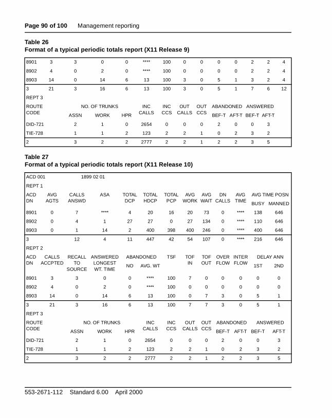
Table 4Periodic management report format (X11 Release 10)
ACD 001 1899 02 01
REPT 1
ACD DN
AVG AGTS
CALLS ANSWD
ASA AVGDCP
AVG PCP
AVG WORK
AVG WAIT
DN CALLS
AVG TIME
AVG TIME POSN
BUSY MANNED
8901 0 7 **** 4 16 20 73 0 **** 138 646
8902 0 4 1 27 0 27 134 0 **** 110 646
8903 0 1 14 2 398 400 246 0 **** 400 646
3 12 4 11 42 54 107 0 **** 216 646
REPT 2
ACDDN
CALLS ACCPTED
RECALL TO
SOURCE
ANSWERED LONGEST WT. TIME
ABNDONED TSF TOFIN
TOFOUT
OVERFLOW
INTERFLOW
DELAY ANN
No AVG. WT
1ST 2ND
8901 3 3 0 0 **** 100 7 0 0 0 0 0
8902 4 0 2 0 **** 100 0 0 0 0 0 0
8903 14 0 14 6 13 100 0 7 3 0 5 1
3 21 3 16 6 13 100 7 7 3 0 5 1
REPT 3
ROUTE CODE
NO. OF TRUNKS INC CALLS
INC CCS
OUT CALLS
OUT CCS
ABANDONED ANSWERED
ASSN WORK HPR BEF-T AFT-T BEF-T AFT-T
DID-721 2 1 0 2654 0 0 0 2 0 0 3
TIE-728 1 1 2 123 2 2 1 0 2 3 2
2 3 2 2 2777 2 2 1 2 2 3 5
REPT 4
POS ID
CALLS ANSWD
AVG DCP
AVG PCP
AVG WAIT
DN INC
INC TIME
DN OUT
OUT TIME
BUSY TIME
MANNED TIME
Q/AGT ID
ACD DN 8901
32 7 4 16 73 0 0 0 0 138 646 4545
ACD DN 8902
20 4 27 0 134 0 0 0 0 110 646 2222
ACD DN 8903
45 1 2 398 246 0 0 0 0 400 646 1313
553-2671-112 Standard 6.00 April 2000
Management reporting Page 53 of 100
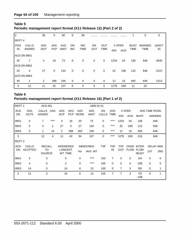
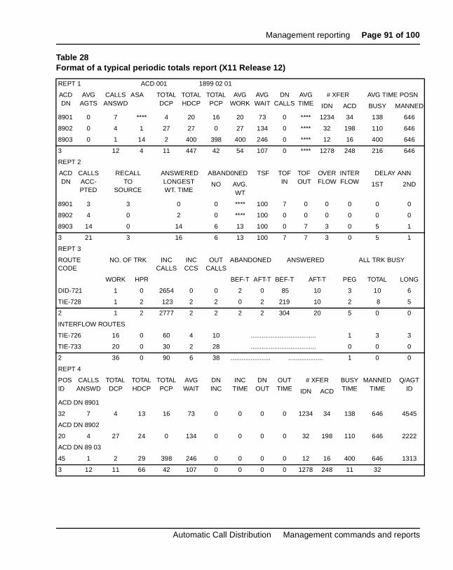
Table 5Periodic management report format (X11 Release 12) (Part 1 of 2)
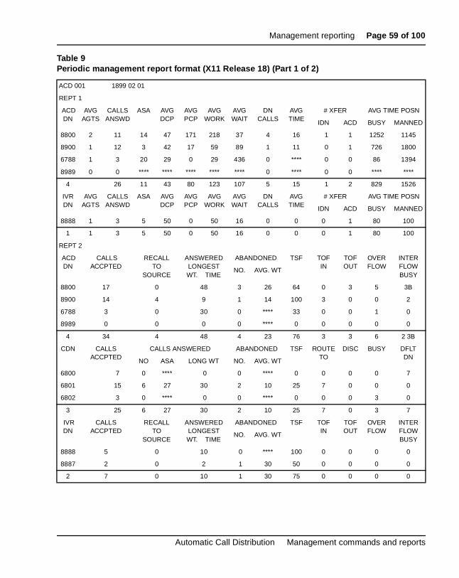
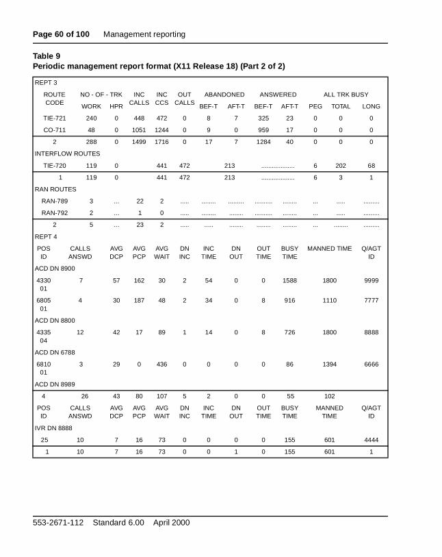
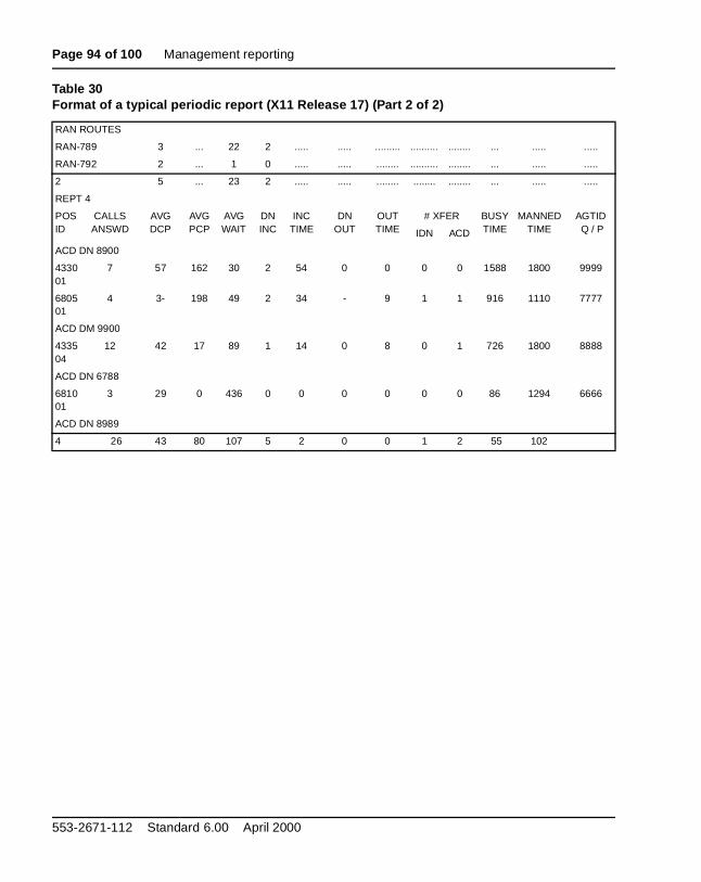
Table 9Periodic management report format (X11 Release 18) (Part 2 of 2)
553-2671-112 Standard 6.00 April 2000
Management reporting Page 61 of 100
from
all .
in the
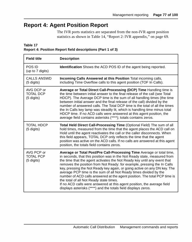
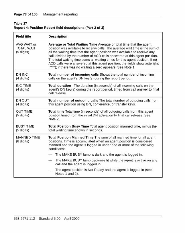
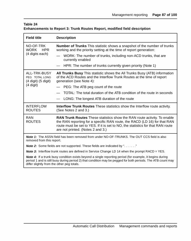
Report 1: Agent Group ReportBeginning with X11 Release 18, the IVR queue statistics are separated the regular queue statistics and appended to Report 1.
Report 1 reflects the activity of the ports used for IVR.
— The CALLS ANSWD field increments when an IVR port answers a cthat was queued to its ACD-DN by way of the ITR for IVR commandThe ASA field reflects only the time the call was queued to this ACD-DN, not the total duration of the call.
— The # XFER field increments when a call is queued to the IVR queueNot CCR-Handled mode, and the IVR port transfers or conferences call. The # XFER field increments when the transfer or conference iscomplete.
Automatic Call Distribution Management commands and reports
Page 62 of 100 Management reporting
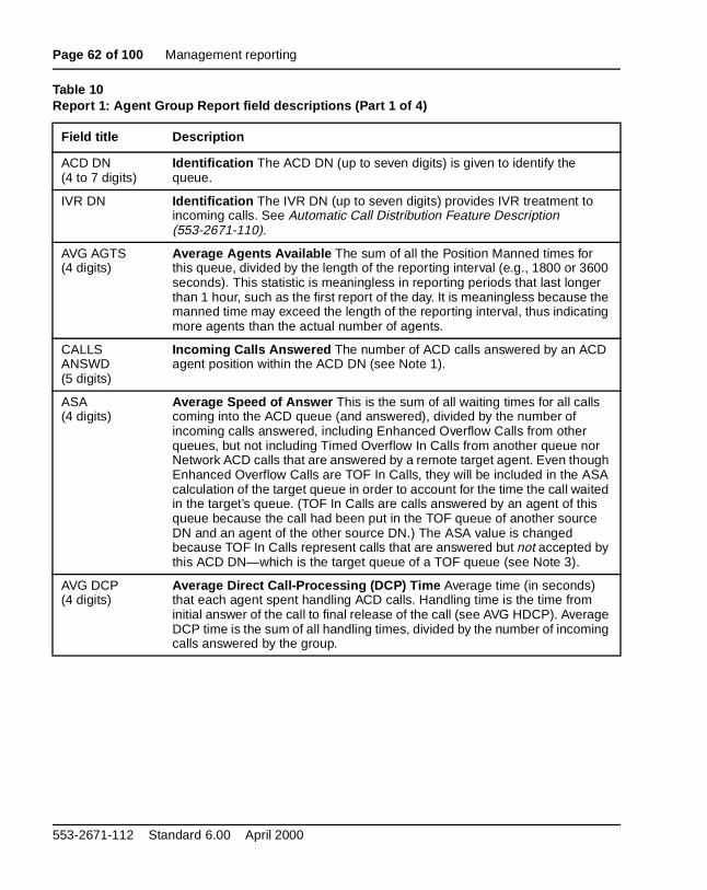
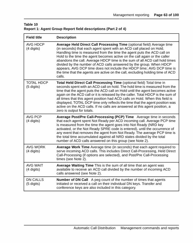
Table 10Report 1: Agent Group Report field descriptions (Part 1 of 4)
Field title Description
ACD DN(4 to 7 digits)
Identification The ACD DN (up to seven digits) is given to identify the queue.
IVR DN Identification The IVR DN (up to seven digits) provides IVR treatment to incoming calls. See Automatic Call Distribution Feature Description (553-2671-110).
AVG AGTS(4 digits)
Average Agents Available The sum of all the Position Manned times for this queue, divided by the length of the reporting interval (e.g., 1800 or 3600 seconds). This statistic is meaningless in reporting periods that last longer than 1 hour, such as the first report of the day. It is meaningless because the manned time may exceed the length of the reporting interval, thus indicating more agents than the actual number of agents.
CALLS ANSWD(5 digits)
Incoming Calls Answered The number of ACD calls answered by an ACD agent position within the ACD DN (see Note 1).
ASA(4 digits)
Average Speed of Answer This is the sum of all waiting times for all calls coming into the ACD queue (and answered), divided by the number of incoming calls answered, including Enhanced Overflow Calls from other queues, but not including Timed Overflow In Calls from another queue nor Network ACD calls that are answered by a remote target agent. Even though Enhanced Overflow Calls are TOF In Calls, they will be included in the ASA calculation of the target queue in order to account for the time the call waited in the target’s queue. (TOF In Calls are calls answered by an agent of this queue because the call had been put in the TOF queue of another source DN and an agent of the other source DN.) The ASA value is changed because TOF In Calls represent calls that are answered but not accepted by this ACD DN—which is the target queue of a TOF queue (see Note 3).
AVG DCP(4 digits)
Average Direct Call-Processing (DCP) Time Average time (in seconds) that each agent spent handling ACD calls. Handling time is the time from initial answer of the call to final release of the call (see AVG HDCP). Average DCP time is the sum of all handling times, divided by the number of incoming calls answered by the group.
553-2671-112 Standard 6.00 April 2000
Management reporting Page 63 of 100
Automatic Call Distribution Management commands and reports
AVG HDCP(4 digits)
Average Held Direct Call Processing Time (optional field) Average time (in seconds) that each agent spent with an ACD call placed on Hold. Handling time is measured from the time the agent puts the ACD call on Hold to the time the agent becomes active on the call again or the caller abandons the call. Average HDCP time is the sum of all ACD call hold times divided by the number of ACD calls answered by the group. When HDCP appears, AVG DCP time does not include the HDCP time; AVG DCP time is the time that the agents are active on the call, excluding holding time of ACD calls.
TOTAL HDCP(5 digits)
Total Held Direct Call Processing Time (optional field) Total time in seconds spent with an ACD call on hold. The hold time is measured from the time that the agent puts the ACD call on Hold until the agent becomes active again on the ACD call or it is released by the caller. Total HDCP is the sum of all times that this agent position had ACD calls on Hold. When this field is displayed, TOTAL DCP time only reflects the time that the agent position was active on the ACD calls. If no calls are answered at this agent position, a zero is output for totals.
AVG PCP(4 digits)
Average Post/Pre Call-Processing (PCP) Time Average time in seconds that each agent spent Not Ready per ACD incoming call. Average PCP time is measured from the time the agent goes into Not Ready (NRD key activated, or the Not Ready SPRE code is entered), until the occurrence of any event that removes the agent from Not Ready. The average PCP time is the total time accumulated against all NRD states divided by the total number of ACD calls answered on this group (see Note 2).
AVG WORK(4 digits)
Average Work Time Average time (in seconds) that each agent required to serve incoming ACD calls. This includes Direct Call-Processing, Held Direct Call-Processing (if options are selected), and Post/Pre Call-Processing times (see Note 2).
AVG WAIT(4 digits)
Average Waiting Time This is the sum of all time that an agent was available to receive an ACD call divided by the number of incoming ACD calls answered (see Note 2).
DN CALLS(5 digits)
Number of DN Call A peg count of the number of times that agents initiated or received a call on their individual DN keys. Transfer and conference keys are also included in this category.
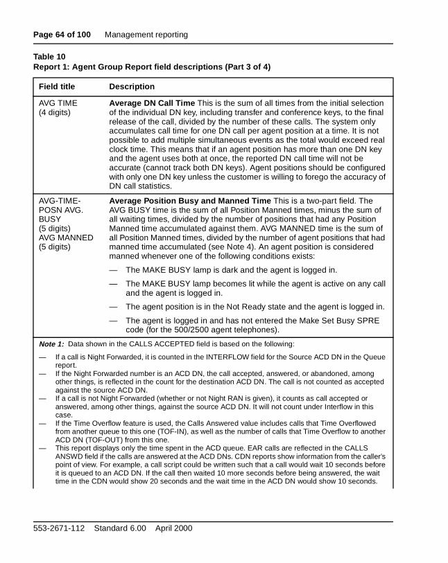
Table 10Report 1: Agent Group Report field descriptions (Part 2 of 4)
Field title Description
Page 64 of 100 Management reporting
AVG TIME(4 digits)
Average DN Call Time This is the sum of all times from the initial selection of the individual DN key, including transfer and conference keys, to the final release of the call, divided by the number of these calls. The system only accumulates call time for one DN call per agent position at a time. It is not possible to add multiple simultaneous events as the total would exceed real clock time. This means that if an agent position has more than one DN key and the agent uses both at once, the reported DN call time will not be accurate (cannot track both DN keys). Agent positions should be configured with only one DN key unless the customer is willing to forego the accuracy of DN call statistics.
Average Position Busy and Manned Time This is a two-part field. The AVG BUSY time is the sum of all Position Manned times, minus the sum of all waiting times, divided by the number of positions that had any Position Manned time accumulated against them. AVG MANNED time is the sum of all Position Manned times, divided by the number of agent positions that had manned time accumulated (see Note 4). An agent position is considered manned whenever one of the following conditions exists:
— The MAKE BUSY lamp is dark and the agent is logged in.
— The MAKE BUSY lamp becomes lit while the agent is active on any call and the agent is logged in.
— The agent position is in the Not Ready state and the agent is logged in.
— The agent is logged in and has not entered the Make Set Busy SPRE code (for the 500/2500 agent telephones).
Note 1: Data shown in the CALLS ACCEPTED field is based on the following:
— If a call is Night Forwarded, it is counted in the INTERFLOW field for the Source ACD DN in the Queue report.
— If the Night Forwarded number is an ACD DN, the call accepted, answered, or abandoned, among other things, is reflected in the count for the destination ACD DN. The call is not counted as accepted against the source ACD DN.
— If a call is not Night Forwarded (whether or not Night RAN is given), it counts as call accepted or answered, among other things, against the source ACD DN. It will not count under Interflow in this case.
— If the Time Overflow feature is used, the Calls Answered value includes calls that Time Overflowed from another queue to this one (TOF-IN), as well as the number of calls that Time Overflow to another ACD DN (TOF-OUT) from this one.
— This report displays only the time spent in the ACD queue. EAR calls are reflected in the CALLS ANSWD field if the calls are answered at the ACD DNs. CDN reports show information from the caller’s point of view. For example, a call script could be written such that a call would wait 10 seconds before it is queued to an ACD DN. If the call then waited 10 more seconds before being answered, the wait time in the CDN would show 20 seconds and the wait time in the ACD DN would show 10 seconds.
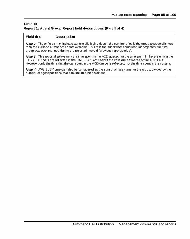
Table 10Report 1: Agent Group Report field descriptions (Part 3 of 4)
Field title Description
553-2671-112 Standard 6.00 April 2000
Management reporting Page 65 of 100
Note 2: These fields may indicate abnormally high values if the number of calls the group answered is less than the average number of agents available. This tells the supervisor doing load management that the group was over-manned during the reported interval (previous report period).
Note 3: This report displays only the time spent in the ACD queue, not the time spent in the system (in the CDN). EAR calls are reflected in the CALLS ANSWD field if the calls are answered at the ACD DNs. However, only the time that the call spent in the ACD queue is reflected, not the time spent in the system.
Note 4: AVG BUSY time can also be considered as the sum of all busy time for the group, divided by the number of agent positions that accumulated manned time.
Table 10Report 1: Agent Group Report field descriptions (Part 4 of 4)
Field title Description
Automatic Call Distribution Management commands and reports
Page 66 of 100 Management reporting
ith ed
w
ve, pears nted
ry The d
and he sy
d
rt
ing
Report 2: Queue ReportReport 2 has been modified with the Time Overflow feature. Beginning wX11 Release 10, the Threshold fields (CWTH, BYTH, OVTH) are removand are replaced by the following field types:
— Recall to Source
— Answered Longest Wait Time
— Time Overflow In and Time Overflow Out
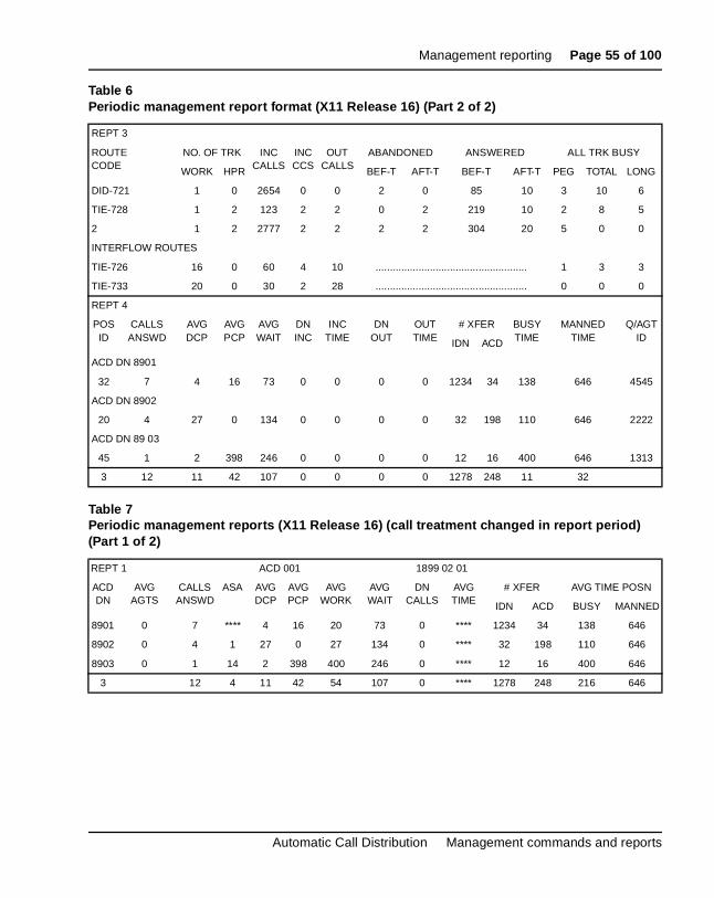
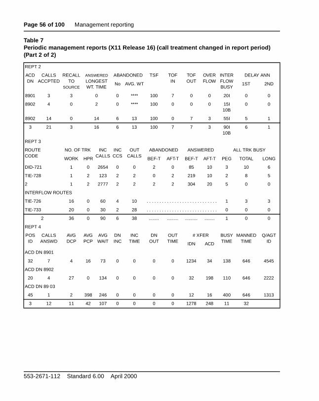
X11 Release 16 added an entry to REPT 2 for the Supervisor Control ofQueue Size feature. The column heading previously labeled Interflow noreads Interflow/Busy. The Interflow and Busy reports are mutually exclusiso a queue may have one or the other listed on the report. If an entry apbecause a CCR IVR call abandons while queued to an IVR queue or preseto a busy treatment, the entry has a “B” beside the numbers. For the entappearing for an interflow treatment, an “I” appears next to the number. totals line appears split with the “B” and “I” labels indicating the busy aninterflow totals independently. It also indicates calls that went to Night treatments if defined in the ACD DN. See Table 6 for an example of management reports with this feature.
If the configuration changes during the period covered by a single report,calls have been treated with both options, a dual line display appears. Tentries are designated with the “B” and “I” indicators. The Interflow or Butreatment is determined in the service change.
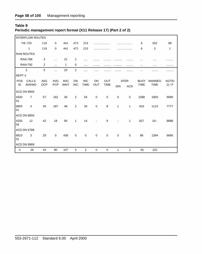
With X11 Release 17, first and second RAN access are no longer peggeagainst the ACD DN queue, and Delay Announcement columns were removed from Report 2. The RAN information is included in the RAN reposection of Report 3.
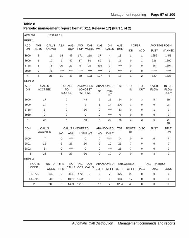
CDN report With X11 Release 17, a report is appended to Report 2 showCDN statistics. This report applies primarily to EAR and CCR calls, withfields showing CDN, CALLS ACCPTED, BUSY, and DFLT DN. Some fields apply to CCR only; some are reserved for future use.
553-2671-112 Standard 6.00 April 2000
Management reporting Page 67 of 100
Table 11Report 2: CDN header format
CDN CALLS ACCPTED
CALLS ANSWERED ABANDONED TSF ROUTE BY DISC BUSY DFL DN
NO ASA LONG WT NO. AVG. WT IVR CCR
6800 7 0 **** 0 0 **** 0 0 1 0 0 7
6801 15 6 27 30 2 10 25 1 1 0 0 0
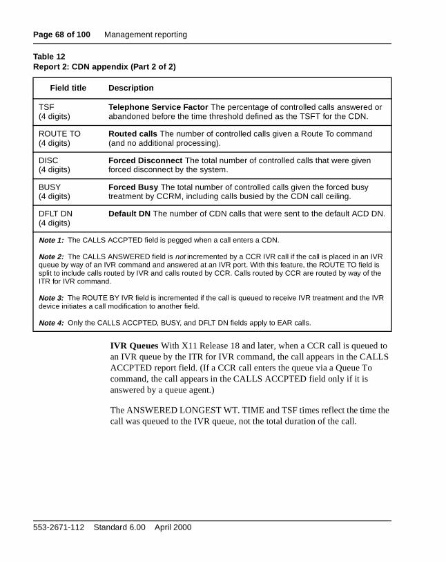
Table 12Report 2: CDN appendix (Part 1 of 2)
Field title Description
CDN(4 to 7 digits)
Control DN This field shows the directory number (up to 7 digits) of the CDN.
CALLS ACCPTED(6 digits)
Calls Accepted The total number of calls entering the CDN and receiving controlled operation or default operation.CALLS ACCPTED = CALLS ANSWERED NO + ABANDONED NO + ROUTE TO + DISC + BUSY +DFLT DN
CALLS ANSWERED NO(5 digits)
Number of Calls Answered The number of calls that entered the CDN and were answered with the controlled operation.
ASA(4 digits)
Average Speed of Answer The average time, in seconds, that each answered ACD call had to wait for an answer. This value is the cumulative total of counts since the last periodic report time. It includes Enhanced Overflow calls, but not Time Overflow (TOF) In Calls nor Network ACD calls from another queue. (TOF In Calls are calls answered by an agent of this queue because the call had been put in the TOF queue of another ACD DN and an agent of this ACD DN was available to answer the call before an agent of the source ACD DN.) The ASA value is changed because TOF In Calls represent calls that are answered but not accepted by this ACD DN—which is the target queue of a TOF queue.
LONG WT(8 digits)
Longest Wait time The longest time a call waited before answer in the CALLS ANSWERED NO field.
ABANDONED NO(3 digits)
Number of Abandoned calls The total number of calls accepted into the CDN but abandoned before being answered through the controlled operation.
AVG WT(4 digits)
Average Wait The total of all waiting times for abandoned calls divided by the number of calls abandoned in the ABANDONED NO field.
Automatic Call Distribution Management commands and reports
Page 68 of 100 Management reporting
to LS
e
IVR Queues With X11 Release 18 and later, when a CCR call is queuedan IVR queue by the ITR for IVR command, the call appears in the CALACCPTED report field. (If a CCR call enters the queue via a Queue To command, the call appears in the CALLS ACCPTED field only if it is answered by a queue agent.)
The ANSWERED LONGEST WT. TIME and TSF times reflect the time thcall was queued to the IVR queue, not the total duration of the call.
TSF(4 digits)
Telephone Service Factor The percentage of controlled calls answered or abandoned before the time threshold defined as the TSFT for the CDN.
ROUTE TO(4 digits)
Routed calls The number of controlled calls given a Route To command (and no additional processing).
DISC(4 digits)
Forced Disconnect The total number of controlled calls that were given forced disconnect by the system.
BUSY(4 digits)
Forced Busy The total number of controlled calls given the forced busy treatment by CCRM, including calls busied by the CDN call ceiling.
DFLT DN(4 digits)
Default DN The number of CDN calls that were sent to the default ACD DN.
Note 1: The CALLS ACCPTED field is pegged when a call enters a CDN.
Note 2: The CALLS ANSWERED field is not incremented by a CCR IVR call if the call is placed in an IVR queue by way of an IVR command and answered at an IVR port. With this feature, the ROUTE TO field is split to include calls routed by IVR and calls routed by CCR. Calls routed by CCR are routed by way of the ITR for IVR command.
Note 3: The ROUTE BY IVR field is incremented if the call is queued to receive IVR treatment and the IVR device initiates a call modification to another field.
Note 4: Only the CALLS ACCPTED, BUSY, and DFLT DN fields apply to EAR calls.
Table 12Report 2: CDN appendix (Part 2 of 2)
Field title Description
553-2671-112 Standard 6.00 April 2000
Management reporting Page 69 of 100
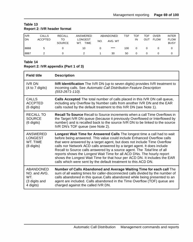
Table 13Report 2: IVR header format
IVR DN
CALLS ACCPTED
RECALL TO
SOURCE
ANSWERED LONGEST WT. TIME
ABANDONED TSF TOF IN
TOF OUT
OVERFLOW
INTER FLOW BUSY
NO. AVG. WT
8888 5 0 10 0 **** 100 0 0 0 0
8887 2 0 2 1 30 50 0 0 0 0
Table 14Report 2: IVR appendix (Part 1 of 3)
Field title Description
IVR DN(4 to 7 digits)
IVR Identification The IVR DN (up to seven digits) provides IVR treatment to incoming calls. See Automatic Call Distribution Feature Description (553-2671-110).
CALLS ACCPTED(6 digits)
Calls Accepted The total number of calls placed in this IVR DN call queue, including any Overflow by Number calls from another IVR DN and the EAR calls routed by the default treatment to this IVR DN (see Note 1).
RECALL TO SOURCE(6 digits)
Recall To Source Recall to Source increments when a call Time Overflows in the Target IVR DN queue (because it previously Overflowed or Interflowed by number) and is recalled back to the source IVR DN to be linked to the source IVR DN’s TOF queue (see Note 2).
ANSWERED LONGEST WT. TIME(8 digits)
Longest Wait Time for Answered Calls The longest time a call had to wait before being answered. This value could include Enhanced Overflow calls that were answered by a target agent, but does not include Time Overflow calls nor Network ACD calls answered by a target agent. It does include Recall to Source calls answered by a source agent. The Total line of all reports shows the Longest Wait Time for all ACD DNs. The hourly report shows the Longest Wait Time for that hour per ACD DN. It includes the EAR calls which were sent by the default treatment to this ACD DN.
ABANDONED NO. and AVG. WT.(3 digits and 4 digits)
Number of Calls Abandoned and Average Waiting Time for each call The sum of all waiting times for caller-disconnected calls divided by the number of calls abandoned in this queue.Calls abandoned while being presented to an agent are included. Calls abandoned in the Time Overflow (TOF) queue are charged against the called IVR DN.
Automatic Call Distribution Management commands and reports
Page 70 of 100 Management reporting
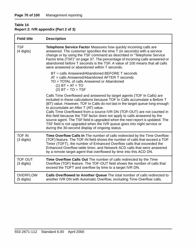
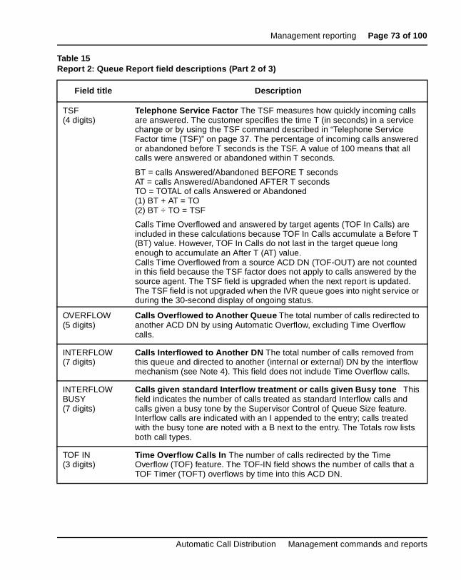
TSF(4 digits)
Telephone Service Factor Measures how quickly incoming calls are answered. The customer specifies the time T (in seconds) with a service change or by using the TSF command as described in “Telephone Service Factor time (TSF)” on page 37. The percentage of incoming calls answered or abandoned before T seconds is the TSF. A value of 100 means that all calls were answered or abandoned within T seconds.
BT = calls Answered/Abandoned BEFORE T secondsAT = calls Answered/Abandoned AFTER T secondsTO = TOTAL of calls Answered or Abandoned
(1) BT + AT = TO(2) BT ÷ TO = TSF
Calls Time Overflowed and answered by target agents (TOF In Calls) are included in these calculations because TOF In Calls accumulate a Before T (BT) value. However, TOF In Calls do not last in the target queue long enough to accumulate an After T (AT) value.Calls Time Overflowed
from a source IVR DN (TOF-OUT) are not counted in
this field because the TSF factor does not apply to calls answered by the source agent. The TSF field is upgraded when the next report is updated. The TSF field is not upgraded when the IVR queue goes into night service or during the 30-second display of ongoing status.
TOF IN(3 digits)
Time Overflow Calls In The number of calls redirected by the Time Overflow (TOF) feature. The TOF-IN field shows the number of calls that exceed a TOF Timer (TOFT), the number of Enhanced Overflow calls that exceeded the Enhanced Overflow table timer, and Network ACD calls that were answered by a remote target agent that overflowed by time into this ACD DN.
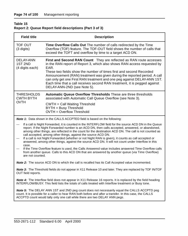
TOF OUT(3 digits)
Time Overflow Calls Out The number of calls redirected by the Time Overflow (TOF) feature. The TOF-OUT field shows the number of calls that exceed the TOFT and overflow by time to a target IVR DN.
OVERFLOW(5 digits)
Calls Overflowed to Another Queue The total number of calls redirected to another IVR DN with Automatic Overflow, excluding Time Overflow calls.
Table 14Report 2: IVR appendix (Part 2 of 3)
Field title Description
553-2671-112 Standard 6.00 April 2000
Management reporting Page 71 of 100
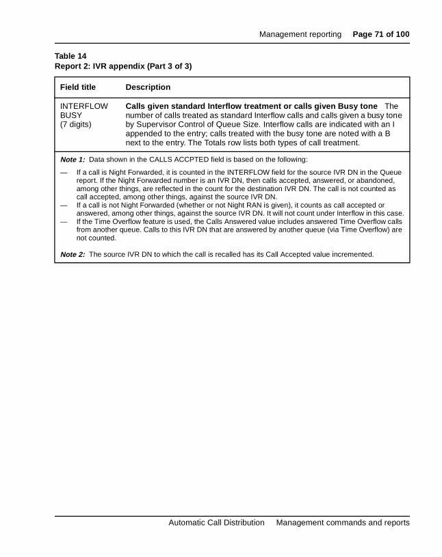
INTERFLOWBUSY(7 digits)
Calls given standard Interflow treatment or calls given Busy tone The number of calls treated as standard Interflow calls and calls given a busy tone by Supervisor Control of Queue Size. Interflow calls are indicated with an I appended to the entry; calls treated with the busy tone are noted with a B next to the entry. The Totals row lists both types of call treatment.
Note 1: Data shown in the CALLS ACCPTED field is based on the following:
— If a call is Night Forwarded, it is counted in the INTERFLOW field for the source IVR DN in the Queue report. If the Night Forwarded number is an IVR DN, then calls accepted, answered, or abandoned, among other things, are reflected in the count for the destination IVR DN. The call is not counted as call accepted, among other things, against the source IVR DN.
— If a call is not Night Forwarded (whether or not Night RAN is given), it counts as call accepted or answered, among other things, against the source IVR DN. It will not count under Interflow in this case.
— If the Time Overflow feature is used, the Calls Answered value includes answered Time Overflow calls from another queue. Calls to this IVR DN that are answered by another queue (via Time Overflow) are not counted.
Note 2: The source IVR DN to which the call is recalled has its Call Accepted value incremented.
Table 14Report 2: IVR appendix (Part 3 of 3)
Field title Description
Automatic Call Distribution Management commands and reports
Page 72 of 100 Management reporting
mes also
.
If a CCR IVR call resides in an IVR queue and an ACD queue agent becoavailable, the call transfers from the IVR queue to the ACD agent. This is true for ACD queue CCR IVR calls presented to an IVR port (applies to interruptible mode IVR only). The IVR-queue pegging shows the call as accepted. No other IVR Queue Report statistics are pegged for that call
Table 15Report 2: Queue Report field descriptions (Part 1 of 3)
Field title Description
ACD DN(4 to 7 digits)
ACD Identification Shows the ACD DN (up to seven digits) of the queue being reported.
IVR DN(4 to 7 digits)
IVR Identification The IVR DN (up to seven digits) provides IVR treatment to incoming calls. See Automatic Call Distribution Feature Description (553-2671-110).
CALLS ACCPTED(6 digits)
Calls Accepted The total number of calls placed in this ACD DN call queue, including any Overflow by Number calls from another ACD DN. Time Overflow calls from another ACD DN are not included. It includes the EAR and CCR calls routed by the default treatment to this ACD DN (see Note 1).
RECALL TO SOURCE(6 digits)
Recall To Source If a call Time Overflows while in the Target ACD DN queue (because it previously Overflowed or Interflowed by number), then it is recalled back to the source ACD DN to be linked to the source ACD DN’s TOF queue and the Recall To Source field increments (see Note 2).
ANSWERED LONGEST WT. TIME(8 digits)
Longest Wait Time for Answered Calls This field shows the longest time a call had to wait before being answered, excluding Time Overflow calls answered by a target agent but including Recall to Source calls answered by a source agent. The total line shows the Longest Wait Time for all ACD DNs. The hourly report shows the Longest Wait Time for that hour per ACD DN, including the EAR and CCR calls sent by default treatment to this ACD DN.
ABANDONED NO. and AVG. WT.(3 digits and 4 digits)
Number of Calls Abandoned and Average Waiting Time for each call This number is the sum of all waiting times for caller-abandoned calls, divided by the number of abandoned calls. The sum includes calls abandoned while being presented to a target queue agent. Calls abandoned while in the Time Overflow (TOF) queue are charged against the called ACD DN.
553-2671-112 Standard 6.00 April 2000
Management reporting Page 73 of 100
TSF(4 digits)
Telephone Service Factor The TSF measures how quickly incoming calls are answered. The customer specifies the time T (in seconds) in a service change or by using the TSF command described in “Telephone Service Factor time (TSF)” on page 37. The percentage of incoming calls answered or abandoned before T seconds is the TSF. A value of 100 means that all calls were answered or abandoned within T seconds.
BT = calls Answered/Abandoned BEFORE T secondsAT = calls Answered/Abandoned AFTER T secondsTO = TOTAL of calls Answered or Abandoned(1) BT + AT = TO(2) BT ÷ TO = TSF
Calls Time Overflowed and answered by target agents (TOF In Calls) are included in these calculations because TOF In Calls accumulate a Before T (BT) value. However, TOF In Calls do not last in the target queue long enough to accumulate an After T (AT) value.Calls Time Overflowed
from a source ACD DN (TOF-OUT) are not counted
in this field because the TSF factor does not apply to calls answered by the source agent. The TSF field is upgraded when the next report is updated. The TSF field is not upgraded when the IVR queue goes into night service or during the 30-second display of ongoing status.
OVERFLOW(5 digits)
Calls Overflowed to Another Queue The total number of calls redirected to another ACD DN by using Automatic Overflow, excluding Time Overflow calls.
INTERFLOW(7 digits)
Calls Interflowed to Another DN The total number of calls removed from this queue and directed to another (internal or external) DN by the interflow mechanism (see Note 4). This field does not include Time Overflow calls.
INTERFLOWBUSY(7 digits)
Calls given standard Interflow treatment or calls given Busy tone This field indicates the number of calls treated as standard Interflow calls and calls given a busy tone by the Supervisor Control of Queue Size feature. Interflow calls are indicated with an I appended to the entry; calls treated with the busy tone are noted with a B next to the entry. The Totals row lists both call types.
TOF IN(3 digits)
Time Overflow Calls In The number of calls redirected by the Time Overflow (TOF) feature. The TOF-IN field shows the number of calls that a TOF Timer (TOFT) overflows by time into this ACD DN.
Table 15Report 2: Queue Report field descriptions (Part 2 of 3)
Field title Description
Automatic Call Distribution Management commands and reports
Page 74 of 100 Management reporting
TOF OUT(3 digits)
Time Overflow Calls Out The number of calls redirected by the Time Overflow (TOF) feature. The TOF-OUT field shows the number of calls that exceed the TOFT and overflow by time to a target ACD DN.
DELAY-ANN 1ST 2ND(4 digits each)
First and Second RAN Count They are reflected as RAN route accesses in the RAN report of Report 3, which also shows RAN access requested by EAR.These two fields show the number of times first and second Recorded Announcement (RAN) treatment was given during the reported period. A call can only get one First RAN treatment and one peg against DELAY-ANN 1ST. Each time that a call receives second RAN treatment, it is pegged against DELAY-ANN-2ND (see Note 5).
THRESHOLDS CWTH BYTH OVTH
Automatic Queue Overflow Thresholds These are three thresholds associated with Automatic Call Queue Overflow (see Note 3).
Note 1: Data shown in the CALLS ACCPTED field is based on the following:
— If a call is Night Forwarded, it is counted in the INTERFLOW field for the source ACD DN in the Queue report. If the Night Forwarded number is an ACD DN, then calls accepted, answered, or abandoned, among other things, are reflected in the count for the destination ACD DN. The call is not counted as call accepted, among other things, against the source ACD DN.
— If a call is not Night Forwarded (whether or not Night RAN is given), it counts as call accepted or answered, among other things, against the source ACD DN. It will not count under Interflow in this case.
— If the Time Overflow feature is used, the Calls Answered value includes answered Time Overflow calls from another queue. Calls to this ACD DN that are answered by another queue (via Time Overflow) are not counted.
Note 2: The source ACD DN to which the call is recalled has its Call Accepted value incremented.
Note 3: The Threshold fields do not appear in X11 Release 10 and later. They are replaced by TOF IN/TOF OUT field reports.
Note 4: The Interflow field does not appear in X11 Release 16 reports. It is replaced by the field heading INTERFLOW/BUSY. This field lists the totals of calls treated with Interflow treatment or Busy tone.
Note 5: The DELAY ANN 1ST and 2ND peg count does not necessarily equal the CALLS ACCPTD peg count. It is possible for a caller to hear RAN both before and after a transfer. In this case, the CALLS ACCPTD count would tally only one call while there are two DELAY ANN pegs.
Table 15Report 2: Queue Report field descriptions (Part 3 of 3)
Field title Description
553-2671-112 Standard 6.00 April 2000
Management reporting Page 75 of 100
ith ainst
Report 3: RAN ReportREPT 3 includes RAN route information in the Interflow routes section. WX11 Release 17 and later, first and second RAN access is not pegged agthe ACD DN queue.
The following table gives information on the fields of Report 3.
Table 16Report 3: Trunk Routes Report field descriptions (Part 1 of 2)
Field title Description
ROUTE CODE(up to 7 digits)
Trunk Route Identification The trunk route access code and the type. (For example, CO, FX, and WATS trunks for all X11 software releases. In addition, DID, CCSA, and Tie trunks for X11 Release 3 and later; RAN trunk route for X11 Release 17 and later.) If the DN expansion package has been included, this field is three spaces longer.
NO-OF-TRKWORK HPR(4 digits)
Number of Trunks A snapshot of the number of trunks assigned and working, plus priorities, at report generation time.
— ASSN The number of trunks (including non-ACD trunks) currently assigned to the trunk route.
— WORK The number of trunks (including non-ACD trunks) that are currently enabled.
— HPR The number of trunks currently given priority.
INC CALLS(6 digits)
Total Number of Incoming Calls Offered The total number of calls that came in on this trunk route (including non-ACD calls) during the report period. The total number of calls per ACD DN equals the total number of INC CALLS for all trunk routes terminating on the ACD DN (see Note 1).
INC CCS(5 digits)
Total Incoming Traffic The total incoming trunk traffic for the trunk route (in CCS) between seizure and disconnect (including non-ACD calls, if any). See Note 2.
OUT CALLS(5 digits)
Total Outgoing Calls The total number of calls outgoing on this route. These are non-ACD calls, but could include outgoing calls made from the DN keys of the ACD agent positions.
OUT CCS(5 digits)
Total Outgoing Traffic This figure shows the outgoing call traffic (in CCS) on the trunk route.
Automatic Call Distribution Management commands and reports
Page 76 of 100 Management reporting
ABANDONED BEF-T AFT-T(5 digits) (6 digits)
ACD Auto-Terminating Trunk Calls Abandoned Two peg counts of calls abandoned showing how many were abandoned before and after the time T used for TSF. The value used for T depends on the trunk involved and on which queue that trunk terminates.The ABANDONED AFT-T field indicates the number of calls abandoned after a customer-defined Time Threshold.
ANSWERED BEF-T AFT-T(6 digits) (5 digits)
ACD Auto-Terminating Trunk Calls Answered The number of calls delayed longer than the customer-specified time is shown in the ANSWERED AFT-T field. The value for T is obtained from the ACD DN whose agent answered the call. If a call time overflows and is answered by a target ACD DN, the value of T set for the target ACD DN is used. When the value of T is set to a minimum value such as 1, all calls encountering any delay are counted as having waited. The definition of calls that have waited too long can be adjusted by changing the T value.
ALL-TRK-BUSY PEG TOTAL LONG(4 digits) (5 digits) (4 digits)
All Trunks Busy This statistic shows the All Trunks Busy (ATB) information of the ACD Routes and the Interflow Trunk Routes at the time of report generation (see Note 3)PEG: The ATB peg count of the routeTOTAL: The total duration of the ATB condition of the route in secondsLONG: The longest ATB duration of the route
Note 1: INC CALLS equals ABANDONED BEF-T AFT-T plus ANSWERED BEF-T AFT-T. Do not try to relate these fields to those of ACD-C reports 1 and 2 (CALLS ANSWD, CALLS ACCPT, and ABANDONED NO). These fields are auto-terminating trunks and reflect how the trunk was first handled (answered or abandoned).
Note 2: Only Route Code, No-of-Trunks Working, INC Calls, and INC CCS apply to the RAN report, X11 Release 17.
Note 3: If a trunk busy condition exists beyond a single reporting period (for example, it begins during period 1 and is still busy during period 2), that condition may be pegged for both periods. The ATB count may differ slightly from the other peg totals.
Table 16Report 3: Trunk Routes Report field descriptions (Part 2 of 2)
Field title Description
553-2671-112 Standard 6.00 April 2000
Management reporting Page 77 of 100
Report 4: Agent Position ReportThe IVR ports statistics are separated from the non-IVR agent position statistics as shown in Table 14, “Report 2: IVR appendix,” on page 69.
Table 17Report 4: Position Report field descriptions (Part 1 of 3)
Field title Description
POS ID(up to 7 digits)
Identification Shows the ACD POS ID of the agent being reported.
CALLS ANSWD(5 digits)
Incoming Calls Answered at this Position Total incoming calls, including Time Overflow calls to this agent position (TOF In Calls).
AVG DCP or TOTAL DCP(5 digits)
Average or Total Direct Call-Processing (DCP) Time Handling time is the time between initial answer to the final release of the call (see Total HDCP). The Average DCP time is the sum of all handling times (the time between initial answer and the final release of the call) divided by the number of answered calls. The Total DCP time is the total of all the times the In Calls key lamp was steadily lit, which is handling time minus total HDCP time. If no ACD calls were answered at this agent position, the average field contains asterisks (****); totals contains zeros.
TOTAL HDCP(5 digits)
Total Held Direct Call-Processing Time (Optional Field) The sum of all hold times, measured from the time that the agent places the ACD call on Hold until the agent reactivates the call or the caller disconnects. When this field appears, TOTAL DCP only reflects the time that the agent position was active on the ACD calls. If no calls are answered at this agent position, the totals field contains zeros.
AVG PCP or TOTAL PCP(5 digits)
Average or Total Post/Pre Call-Processing Time Average or total time, in seconds, that this position was in the Not Ready state, measured from the time that the agent activates the Not Ready key until any event that removes the position from Not Ready: for example, pressing the In Calls key, pressing the Not Ready key again, or going active on any DN key. The average PCP time is the sum of all Not Ready times divided by the number of ACD calls answered at the agent position. The total PCP time is the total of all Not Ready state times.If no ACD calls were answered at this agent position, the average field displays asterisks (****) and the totals field displays zeros.
Automatic Call Distribution Management commands and reports
Page 78 of 100 Management reporting
AVG WAIT or TOTAL WAIT(5 digits)
Average or Total Waiting Time Average or total time that the agent position was available to receive calls. The average wait time is the sum of all the waiting time that the agent position was available to receive any call, divided by the number of ACD calls answered at this agent position. The total waiting time sums all waiting times for this agent position. If no ACD calls were answered at this agent position, the fields show asterisks (****); if there was no waiting a zero appears. See Note 1.
DN INC(4 digits)
Total number of incoming calls Shows the total number of incoming calls on the agent’s DN key(s) during the report period.
INC TIME(4 digits)
Total duration The duration (in seconds) of all incoming calls on the agent’s DN key(s) during the report period, timed from call answer to final call release.
DN OUT(4 digits)
Total number of outgoing calls The total number of outgoing calls from this agent position using DN, conference, or transfer keys.
OUT TIME(5 digits)
Total time Total time (in seconds) of all outgoing calls from this agent position timed from the initial DN activation to final call release. See Note 2.
BUSY TIME(5 digits)
Total Position Busy Time Total agent position manned time, minus the total waiting time shown in seconds.
MANNED TIME(6 digits)
Total Position Manned Time The sum of all manned time for all agent positions. Time is accumulated when an agent position is considered manned and the agent is logged in under one or more of the following conditions:
— The MAKE BUSY lamp is dark and the agent is logged in.
— The MAKE BUSY lamp becomes lit while the agent is active on any call and the agent is logged in.
— The agent position is Not Ready and the agent is logged in (see Notes 1 and 2).
Table 17Report 4: Position Report field descriptions (Part 2 of 3)
Field title Description
553-2671-112 Standard 6.00 April 2000
Management reporting Page 79 of 100
l h Ns
Ongoing Status DisplayThe Ongoing Status Display is presented on the Video Display Termina(VDT) display, and updated every 30 or 60 seconds, as specified througACD Service Change. The Ongoing Status Display reports on both ACD Dand CDNs for the customer.
AGT IDQ / P(4 digits)
Agent Identification (Optional Field) The ACD AGENT ID of the agent being reported. This field appears when Report Control in Service Change LD 23 defines the Short Report and Agent ID options as YES. If a new agent occupies the agent position, the ID of the previous agent appears, accompanied by an asterisk.
Note: If an agent is not logged in when the report is generated, the Agent ID will not appear in the report.
One or more Short Reports with Agent ID are generated when one or more of the following conditions exist:
— A new agent logs in to an agent position that was manned by another logged in agent. In this case the Q/AGT ID field will show the Agent ID of the previous agent. The line of statistics reflects data accumulated for the previously logged-in agent.
— The position is moved from one ACD group (ACD DN) to another. In this case, the Q/AGT ID field will display the queue identification of the queue to which the agent was formerly assigned.
— The priority of the Agent at the time of printing appears under the Agent ID.
Note 1: All of the REPT 4 time fields are reported as currently manned (or previously, if not currently manned). If the optional AGENT ID is used along with Short Reports, the Short Report will show all of the time for the agent position during the reported period.
Note 2: If an agent is involved in a conference call or an IDN call, or is transferring a call when the report is generated, the OUT TIME field includes the call start time minus the current time. The DN OUT and XFER IDN fields are not incremented until the call is released, and they are reflected in the next reporting period.
Note 3: The INC TIME and the OUT TIME fields do not include the amount of time the IDN call was on hold.
Table 17Report 4: Position Report field descriptions (Part 3 of 3)
Field title Description
Automatic Call Distribution Management commands and reports
Page 80 of 100 Management reporting
as
n is
EAR The TSF, ASA, and #CALLS IN QUEUE fields include EAR calls routed by the default treatment to the ACD DN since these calls are treatedif they had entered the queue directly. CDNs do not appear in the statusdisplay, as incoming CDN calls are routed to the default ACD DN immediately.
Ongoing Status report control determines if the ongoing status informatioprinted. If RPRT is no, ongoing status reports are not printed.
An example of the Ongoing Status Display Output is shown in Table 18.
CCR Ongoing Status Display appears for CDNs if it is in the controlled mode.
The Queue To command sends CCR calls to an ACD DN. The ACD DN#CALLS IN QUEUE field does not include the CCR calls. The TSF and ASAfields only include CCR calls answered by agents of this ACD DN.
Table 18Ongoing Status Display format
ACD DN
TSF ASA # CALLS IN QUEUE
# POS MANNED
# POS DCP
# POS PCP
# POS WTG
# POS NON ACD
# VIRTUALCALLS QD
2222 100 2 0 1 0 1 0 0 0
5555 46 120 8 1 1 0 0 0 0
ACD DN
TSF ASA # CALLS IN QUEUE
# POS MANNED
# POS DCP
# POS PCP
# POS WTG
# POS NON ACD
# VIRTUALCALLS QD
2222 100 2 0 1 0 1 0 0 0
5555 45 184 7 2 2 0 0 0 0
ACD DN
TSF ASA # CALLS IN QUEUE
# POS MANNED
# POS DCP
# POS PCP
# POS WTG
# POS NON ACD
# VIRTUALCALLS QD
2222 100 2 0 1 0 1 0 0 0
5555 44 242 6 3 3 0 0 0 0
ACD DN
TSF ASA # CALLS IN QUEUE
# POS MANNED
# POS DCP
# POS PCP
# POS WTG
# POS NON ACD
# VIRTUALCALLS QD
2222 100 2 0 3 1 1 1 0 0
5555 44 296 5 4 4 0 0 0 0
ACD DN
TSF ASA # CALLS IN QUEUE
# POS MANNED
# POS DCP
# POS PCP
# POS WTG
# POS NON ACD
# VIRTUALCALLS QD
2222 100 2 0 3 1 1 1 0 0
5555 44 296 5 4 4 0 0 0 0
553-2671-112 Standard 6.00 April 2000
Management reporting Page 81 of 100
CD A,
ned
this
he e s
If the CCR feature is used, the Ongoing Status Display reports on both ADNs and CDNs for the customer. CDNs have values only in the TSF, ASand #CALLS IN QUEUE fields; all other fields contain asterisks.
The fields are as follows:
— # CALLS IN QUEUE reflects the total controlled calls in the system that originated from this CDN.
— TSF indicates the percentage of controlled calls answered or abandobefore a certain threshold (TSFT).
— ASA displays the average speed of answer for the calls that enteredCDN and were answered through the controlled operation.
If load management or error conditions change the CDN to default mode from controlled mode, the Ongoing Status still appears. The Ongoing Status Display does not show the CDNs if they are always in the default mode.Abnormal conditions that divert new calls to the default ACD DN prevent tCDN #CALLS IN QUEUE field from incrementing until a Start Up messagis received, although the CDN continues to appear on the Ongoing Statureport.
Automatic Call Distribution Management commands and reports
Page 82 of 100 Management reporting
wn
An example of the Ongoing Status Display Output for CCR CDNs is shoin Table 20.
Table 19Ongoing Status Display field descriptions (Part 1 of 2)
Field title Description
ACD DN(4 to 7 digits)
Identification Shows the ACD DN of the queue being reported.
TSF(3 digits)
Telephone Service Factor The percentage of incoming calls answered or abandoned before T seconds is the TSF. The customer specifies the time T in seconds with a service change or the TSF command as described in “Telephone Service Factor time (TSF)” on page 37. A value of 100 means that all calls were answered or abandoned within T seconds.
BT = calls Answered/Abandoned BEFORE T secondsAT = calls Answered/Abandoned AFTER T secondsTO = TOTAL of calls Answered or Abandoned
(1) BT + AT = TO(2) BT ÷ TO = TSF
Calls Time Overflowed and answered by target agents (TOF In Calls) are included in these calculations because TOF In Calls accumulate a Before T (BT) value. However, TOF In Calls do not last in the target queue long enough to accumulate an After T (AT) value.
Calls Time Overflowed from a source ACD DN (TOF-OUT) are not counted in this field because the TSF factor does not apply to calls answered by the source agent.
ASA(3 digits)
Average Speed of Answer This is the average time, in seconds, that each answered ACD call had to wait for an answer, excluding Time Overflow (TOF) In Calls from another queue that were answered by an agent of this queue because an agent of this ACD DN was available before an agent of the source ACD DN was. The ASA value changes because TOF In Calls reflect calls that are answered but not accepted by this ACD DN, the target queue of a TOF queue.
# CALLS IN QUEUE(5 digits)
Number of Calls in Queue This is a snapshot of the number of calls awaiting service in this queue, but not yet connected to an agent position. It includes calls in the queue’s Time Overflow queue and sent by a CDN with the default treatment.
# POS MANNED
Number of Manned Positions The number of agent positions associated with this queue for which the MAKE BUSY lamp is dark.
553-2671-112 Standard 6.00 April 2000
Management reporting Page 83 of 100
# POS DCP Agents Direct Call-Processing The number of agent positions currently active on the In Calls key, including those that have the ACD calls on Hold.
# POS PCP Agents Post Call-Processing Snapshot of the number of agent positions currently in Not Ready state.
# POS WTG Positions Waiting Snapshot of the number of agent positions currently available to receive an incoming ACD call.
# POS NON-ACD
Positions on Non-ACD Calls Snapshot of the number of agents active on a key other than the In Calls key.
# VIRTUALCALLS QD
Number of Virtual Calls Queued The number of Source Time Overflow, Call Request Queue, and CCR calls in queue. Virtual calls include Timed Overflow, Enhanced Overflow, and Customer Controlled Routing calls.
Table 20CCR Ongoing Status Display field descriptions
Field title Description
TSF(3 digits)
Telephone Service Factor The percentage of CCR calls in controlled mode that were answered or abandoned before the TSF threshold.
ASA(3 digits)
Average Speed of Answer The average speed of answer for the calls that entered this CDN and were answered through the controlled operation.
# CALLS IN QUEUE(5 digits)
Number of calls in queue This reflects the total controlled CDN calls in the system that originated from this CDN. Refer to the Note.
Note: If an abnormal condition occurs (for example, the link going down), new calls are diverted to the default ACD DN. If this happens, the CDN still appears on the ongoing status report, but the #CALLS IN QUEUE field for the CDN does not increment until a Start Up message is received from the CCRM application module.
The #CALLS IN QUEUE field for the ACD DNs does not include the CCR calls. CCR calls are calls that are queued to an ACD DN by a Queue To command from the CCRM application module. The TSF and ASA fields include the CCR calls only if they were answered by agents of this ACD DN. The #CALLS IN QUEUE field for the CDN increments when calls enter the CDN and are controlled by the CCRM application.
Table 19Ongoing Status Display field descriptions (Part 2 of 2)
Field title Description
Automatic Call Distribution Management commands and reports
Page 84 of 100 Management reporting
ot do
egin
o ribed
2.
rk
Asterisks appear in the # VIRTUAL CALLS QD field because a CDN cannhave virtual calls queued to it. In Table 21, all fields shown with asterisksnot apply for CDNs.
Short ReportsA short report prints after an agent logs in to an agent position occupiedearlier in the reporting period by another agent. The report contains the statistics accumulated for the old agent before the move. New statistics baccumulating on the new agent as soon as the move occurs.
Short Reports are also generated when the physical position is moved tanother queue by using the SAPA Load Management Command as descin “Select Agent Position Assignment (SAPA)” on page 28.
An Agent Position Report (indicating a Short Report) is shown in Table 2The Short Report prints as agent 15 logs into position 3832, which was previously occupied by agent 11. Note that this report reflects the work performed by agent 11 while occupying this position. The next regularly scheduled Report 4 indicates the work performed by agent 15 during theremainder of the reporting period. The system totals line includes the woperformed by agent 11.
Table 21CCR Ongoing Status Display field description for CCR CDN (5555)
ACDDN
TSF ASA #CALLSIN QUEUE
#POSMANNED
#POSDCP
#POSPCP
#POSWTG
#POSNON-ACD
#VIRTUALCALLS QD
2222 100 2 5 1 0 1 0 0 0
5555 46 50 10 **** **** **** **** **** ****
Table 22Report 4: Short Report
POS ID
CALLS ANSWD
AVG DCP
AVG PCP
AVG WAIT
DN INC
INC TIME
DN OUT
OUT TIME
# XFER BUSY TIME
MANNED TIME
AGTIDQ/PIDN ACD
3832 8 152 12 20 0 0 0 0 0 2 1865 2403 11A
Note: Letters indicate how the agent position was changed: A = Agent logout/loginP = Agent’s priority changed using SAGP/LAGP commandQ = Agent moved to new queue using SAPA/LAPA command
553-2671-112 Standard 6.00 April 2000
Management reporting Page 85 of 100
e
mits ded
tal
f the
DE port. an
otals.
4), tics rrent sted e is s:
ed
Enhanced daily totals
The customer can schedule cumulative Enhanced Reports 1, 2, 3, and 4 for
the end of each daily period. The report format is the same as that for thhourly/half-hourly reports, but the averages and totals reflect a 24-hour period, defined by start and end times. A start and end time of 0 hours perreports to be printed at midnight. The system total line of statistics is incluin each daily report.
For Report 1, the fields DN CALLS, BUSY TIME, and MANNED TIME show the total of all the individual reports (total number of DN calls and toof AVG and MANNED times). The # XFER IDN and ACD fields reflect totals, as in other scheduled reports. The other fields are the averages oinformation on all of the individual reports, except for ABANDONED AVGWT and TSF, which are the averages of all the individual reports.
For Report 3, if the DN Expansion package is included, the ROUTE COfield is three spaces larger. The result is more than 80 columns in each reFor both situations, the reports are not completely shown if the printer is80-character printer. Figures 22 through 17 show typical report formats.
The senior supervisor can issue two commands to see daily and system tThe commands are DTOT (Daily Totals) and STOT (System Totals).
DTOT This command, followed by the desired report number (1, 2, 3, orpresents a Daily Totals report on the senior supervisor’s terminal. Statisshown in the reports are those accumulated since the beginning of the cudaily period to the current time and include system totals for each requereport. If an initialization occurs in the reporting period, an INI00 messagpresented preceding the DTOT report. The command format is as follow
After the ACD report for Report 2 is printed, a new CDN report is appendto the end of the ACD Report 2.
DTOT X
Legend:
X = Report number (1, 2, 3, or 4)
Automatic Call Distribution Management commands and reports
Page 86 of 100 Management reporting
4), istics ort.
ed
to
ll
ned
STOT This command, followed by the desired report number (1, 2, 3, orpresents a System Totals report on the senior supervisor’s terminal. Statin the reports are those accumulated since the last hourly/half-hourly repIf an initialization occurred in the reporting period, a message is presentbefore the STOT report. The command format is as follows:
After the ACD report for Report 2 prints, a new CDN report is appendedthe end of the ACD Report 2. For information about the Time Overflow feature, see “Time Overflow threshold (TLDD)” on page 36.
Note: If the ACD Report Control feature is enabled and reports for aACD DNs are turned off, the only report printed is Report 3, Trunks.
Tables 23 through 25 provide a description of the new data fields contaiin the Enhanced Reports feature available in X11 Release 12 and later software packages.
STOT X
Legend:
X = Report number (1, 2, 3, or 4)
Table 23Enhancements to Report 1: Agent Group Report added field description
Field title Description
# XFER IDN# XFER ACD(4 digits each)
Number of Calls Transfer/Conference This is a two-part field added in X11 Release 12. The # XFER IDN count is the sum of all the calls the agent transferred or conferenced while on an active IDN call. The # XFER ACD count is the sum of all the calls the agent transferred or conferenced while on an active ACD call. Before X11 Release 12, transferred or conferenced calls were included in the DN CALLS column.
553-2671-112 Standard 6.00 April 2000
Management reporting Page 87 of 100
Table 24Enhancements to Report 3: Trunk Routes Report, modified field description
Field title Description
NO-OF-TRK WORK HPR(4 digits each)
Number of Trunks This statistic shows a snapshot of the number of trunks working and the priority setting at the time of report generation:
— WORK: The number of trunks, including non-ACD trunks, that are currently enabled
— HPR: The number of trunks currently given priority (Note 1)
ALL-TRK-BUSY PEG TOTAL LONG
(4 digit) (5 digit) (4 digit)
All Trunks Busy This statistic shows the All Trunks Busy (ATB) information of the ACD Routes and the Interflow Trunk Routes at the time of report generation (see Note 4):
— PEG: The ATB peg count of the route
— TOTAL: The total duration of the ATB condition of the route in seconds
— LONG: The longest ATB duration of the route
INTERFLOW ROUTES
Interflow Trunk Routes These statistics show the Interflow route activity. (See Notes 2 and 3.)
RAN ROUTES
RAN Trunk Routes These statistics show the RAN route activity. To enable the RAN reporting for a specific RAN route, the RACD (LD 16) for that RAN route must be set to YES. If it is set to NO, the statistics for that RAN route are not printed. (Notes 2 and 3.)
Note 1: The ASSN field has been removed from under NO-OF-TRUNKS. The OUT CCS field is also removed from this report.
Note 2: Some fields are not supported. These fields are indicated by “. . . . . . .”
Note 3: Interflow trunk routes are defined in Service Change LD 14 when the prompt RACD = YES.
Note 4: If a trunk busy condition exists beyond a single reporting period (for example, it begins during period 1 and is still busy during period 2) that condition may be pegged for both periods. The ATB count may differ slightly from the other peg totals.
Automatic Call Distribution Management commands and reports
Page 88 of 100 Management reporting
at of of the
tals .
otals
t as
it
DN.
Beginning with X11 Release 18, the Daily Totals Report separates IVR statistics and CDN reporting changes. The print format is the same as ththe regular reports. The daily report data reflects the totals and averages data accumulated over the daily reporting period
Daily system totalsA line of statistics prints at the bottom of each report, showing system tofor all report data for all ACD DN/Pos IDs in a customer’s ACD operation
A few of the report data items do not have system totals or have system texpressed in different units from those of the individual fields. The discrepancies between individual fields and total fields are listed by reporfollows:
Report 1 Agent Group The number in the ACD DN field reflects the totalnumber of ACD DNs. Data for the AVG AGTS field does not appear as represents a customer decision, not ACD group performance.
Report 2 Call Queue The number shown in the ACD DN field reflects thetotal number of ACD DN.
CDN statistics are appended to the end of Report 2 and have a differentheader. The CDN reports detail the treatment for all calls that enter the CFor detailed information on this report, refer to Table 12, “Report 2: CDNappendix,” on page 67.
Table 25Enhancements to Report 4: Position Report added field description
Field title Description
# XFER IDN# XFER ACD(4 digits each)
Number of Calls Transfer/Conference This is a two-part field that is added in X11 Release 12. The # XFER IDN count is the sum of all the calls transferred or conferenced that were originated by the agent while on an active IDN call. The # XFER ACD count is the sum of all the calls transferred or conferenced that were originated by the agent while on an active ACD call. Before X11 Release 12, transferred or conferenced calls were included in the DN OUT column. When the Total (TOT4) option is enabled, the BUSY TIME field is eliminated to allow room for this column.
The time associated with the calls is displayed in the OUT TIME field.
553-2671-112 Standard 6.00 April 2000
Management reporting Page 89 of 100
ows s,
s
for
rage uld
4), istics ort.
Report 3 Trunk Routes The numbers reflect the total number of trunks reported on the system. Report fields include the ROUTE CODE that shall trunks that auto-terminate on all customer ACD DNs, Interflow Routeand RAN Routes.
Report 4 Agent Position The number shown in the Pos ID field representthe total number of Pos IDs in the customer’s operation. Data for the INCTIME, OUT TIME, BUSY TIME, and MANNED TIME fields are expressedin minutes. The other fields are expressed in seconds. The system totalsall total fields are expressed in minutes, while the system totals for all avefields are expressed in seconds. The AGT ID field is not reported as it woshow the same total as the Pos ID.
Note: The maximum total MANNED TIME supported is 18 hours, 12minutes, and 15 seconds (65535 seconds total).
STOT This command, followed by the desired report number (1, 2, 3, orpresents a System Totals report on the senior supervisor’s terminal. Statin the report(s) are those accumulated since the last hourly/half-hourly rep
Table 26Format of a typical periodic totals report (X11 Release 9)
ACD 001 1899 02 01
REPT 1
ACD DN
AVG AGTS
CALLS ANSWD
ASA TOTALDCP
TOTAL HDCP
TOTAL PCP
AVG WORK
AVG WAIT
DN CALLS
AVG TIME
AVG TIME POSN
BUSY MANNED
8901 0 7 **** 4 20 16 20 73 0 **** 138 646
8902 0 4 1 27 27 0 27 134 0 **** 110 646
8903 0 1 14 2 400 398 400 246 0 **** 400 646
3 12 4 11 447 42 54 107 0 **** 216 646
REPT 2
ACDDN
CALLS ACCPTED
RECALL TO
SOURCE
ANSWERED LONGEST WT. TIME
ABAND0NED TSF OVER FLOW
INTERFLOW
DELAY ANN THRESHOLDS
NO AVG. WT 1ST 2ND CWTH BVTH OVTH
Automatic Call Distribution Management commands and reports
Page 90 of 100 Management reporting
8901 3 3 0 0 **** 100 0 0 0 0 2 2 4
8902 4 0 2 0 **** 100 0 0 0 0 2 2 4
8903 14 0 14 6 13 100 3 0 5 1 3 2 4
3 21 3 16 6 13 100 3 0 5 1 7 6 12
REPT 3
ROUTE CODE
NO. OF TRUNKS INC CALLS
INC CCS
OUT CALLS
OUT CCS
ABANDONED ANSWERED
ASSN WORK HPR BEF-T AFT-T BEF-T AFT-T
DID-721 2 1 0 2654 0 0 0 2 0 0 3
TIE-728 1 1 2 123 2 2 1 0 2 3 2
2 3 2 2 2777 2 2 1 2 2 3 5
Table 27Format of a typical periodic totals report (X11 Release 10)
ACD 001 1899 02 01
REPT 1
ACD DN
AVG AGTS
CALLS ANSWD
ASA TOTALDCP
TOTAL HDCP
TOTAL PCP
AVG WORK
AVG WAIT
DN CALLS
AVG TIME
AVG TIME POSN
BUSY MANNED
8901 0 7 **** 4 20 16 20 73 0 **** 138 646
8902 0 4 1 27 27 0 27 134 0 **** 110 646
8903 0 1 14 2 400 398 400 246 0 **** 400 646
3 12 4 11 447 42 54 107 0 **** 216 646
REPT 2
ACDDN
CALLS ACCPTED
RECALL TO
SOURCE
ANSWERED LONGEST WT. TIME
ABANDONED TSF TOF IN
TOF OUT
OVER FLOW
INTERFLOW
DELAY ANN
NO AVG. WT 1ST 2ND
8901 3 3 0 0 **** 100 7 0 0 0 0 0
8902 4 0 2 0 **** 100 0 0 0 0 0 0
8903 14 0 14 6 13 100 0 7 3 0 5 1
3 21 3 16 6 13 100 7 7 3 0 5 1
REPT 3
ROUTE CODE
NO. OF TRUNKS INC CALLS
INC CCS
OUT CALLS
OUT CCS
ABANDONED ANSWERED
ASSN WORK HPR BEF-T AFT-T BEF-T AFT-T
DID-721 2 1 0 2654 0 0 0 2 0 0 3
TIE-728 1 1 2 123 2 2 1 0 2 3 2
2 3 2 2 2777 2 2 1 2 2 3 5
Table 26Format of a typical periodic totals report (X11 Release 9)
553-2671-112 Standard 6.00 April 2000
Management reporting Page 91 of 100
Table 28Format of a typical periodic totals report (X11 Release 12)