60
Software manual H-9931-9505-01-A MERLIN system Calibration in HYPACK HYSWEEP For end users, installers, integrators and engineers DRAFT ONLY

1
Con
tent
s
Software manualH-9931-9505-01-A
MERLIN systemCalibration in HYPACK HYSWEEP
For end users, installers, integrators and engineers
DRAFT ONLY

Disclaimer
RENISHAW HAS MADE CONSIDERABLE EFFORTS TO ENSURE THE CONTENT OF THIS DOCUMENT IS CORRECT AT THE DATE OF PUBLICATION BUT MAKES NO WARRANTIES OR REPRESENTATIONS REGARDING THE CONTENT. RENISHAW EXCLUDES LIABILITY, HOWEVER ARISING, FOR ANY INACCURACIES IN THIS DOCUMENT.
Laser safety
DO NOT STARE DIRECTLY INTO THE BEAM
The MERLIN system is classified as a Class 1 invisible laser product. Please refer to the user manual for full details relating to the laser safety of your equipment.
© 2015 Renishaw plc. All rights reserved.
This document may not be copied or reproduced in whole or in part, or transferred to any other media or language, by any means, without the prior written permission of Renishaw plc.
The publication of material within this document does not imply freedom from the patent rights of Renishaw plc.
Trade marks
RENISHAW and the probe symbol used in the RENISHAW logo are registered trade marks of Renishaw plc in the United Kingdom and other countries. apply innovation and names and designations of other Renishaw products and technologies are trade marks of Renishaw plc or its subsidiaries.
All other brand names and product names used in this document are trade names, trade marks, or registered trade marks of their respective owners.
Care of equipment
Renishaw’s MERLIN marine laser scanning system and associated accessory products are precision products and must therefore be treated with care.
Changes to Renishaw products
Renishaw plc reserves the right to improve, change or modify its products and documentation without incurring any obligation to make changes to equipment previously sold or distributed.
Renishaw part no: H-9931-9505-01-A
Issued: 12.2015
DRAFT ONLY

i
Con
tent
s
Contents
1 Customer information . . . . . . . . . . . . . . . . . . . . . . . . . . . . . . . . . . . . . . . . . . . . . . . . . . . . 1-1
1.1 Dear Customer . . . . . . . . . . . . . . . . . . . . . . . . . . . . . . . . . . . . . . . . . . . . . . . . . . . 1-1
1.2 Manual overview . . . . . . . . . . . . . . . . . . . . . . . . . . . . . . . . . . . . . . . . . . . . . . . . . . 1-1
2 MERLIN set-up and configuration . . . . . . . . . . . . . . . . . . . . . . . . . . . . . . . . . . . . . . . . . . . 2-1
2.1 Hardware set-up . . . . . . . . . . . . . . . . . . . . . . . . . . . . . . . . . . . . . . . . . . . . . . . . . . 2-1
2.2 Enable HYSWEEP . . . . . . . . . . . . . . . . . . . . . . . . . . . . . . . . . . . . . . . . . . . . . . . . 2-3
2.3 Merlin configuration. . . . . . . . . . . . . . . . . . . . . . . . . . . . . . . . . . . . . . . . . . . . . . . . 2-4
2.4 Merlin network test . . . . . . . . . . . . . . . . . . . . . . . . . . . . . . . . . . . . . . . . . . . . . . . . 2-6
2.5 Merlin offsets. . . . . . . . . . . . . . . . . . . . . . . . . . . . . . . . . . . . . . . . . . . . . . . . . . . . . 2-8
2.6 Merlin rotation . . . . . . . . . . . . . . . . . . . . . . . . . . . . . . . . . . . . . . . . . . . . . . . . . . . . 2-9
2.6.1 MERLIN default values. . . . . . . . . . . . . . . . . . . . . . . . . . . . . . . . . . . . . . . 2-9
2.6.1.1 Roll . . . . . . . . . . . . . . . . . . . . . . . . . . . . . . . . . . . . . . . . . . . . . . . 2-9
2.6.1.2 Pitch . . . . . . . . . . . . . . . . . . . . . . . . . . . . . . . . . . . . . . . . . . . . . 2-10
2.6.1.3 Yaw (heading) . . . . . . . . . . . . . . . . . . . . . . . . . . . . . . . . . . . . . . 2-10
3 MERLIN operation in HYSWEEP . . . . . . . . . . . . . . . . . . . . . . . . . . . . . . . . . . . . . . . . . . . 3-1
3.1 MERLIN control screen. . . . . . . . . . . . . . . . . . . . . . . . . . . . . . . . . . . . . . . . . . . . . 3-1
3.2 Functionality . . . . . . . . . . . . . . . . . . . . . . . . . . . . . . . . . . . . . . . . . . . . . . . . . . . . . 3-4
3.3 Real-time data visualisation . . . . . . . . . . . . . . . . . . . . . . . . . . . . . . . . . . . . . . . . . 3-7
3.3.1 Topographic Laser window. . . . . . . . . . . . . . . . . . . . . . . . . . . . . . . . . . . . 3-7
3.3.2 HYPACK Real Time Cloud window. . . . . . . . . . . . . . . . . . . . . . . . . . . . . 3-11
3.3.2.1 HYPACK Real Time Cloud tools . . . . . . . . . . . . . . . . . . . . . . . . 3-12
4 Calibrating MERLIN via a patch test . . . . . . . . . . . . . . . . . . . . . . . . . . . . . . . . . . . . . . . . . 4-1
4.1 Vessel-mounted calibration patch test . . . . . . . . . . . . . . . . . . . . . . . . . . . . . . . . . 4-1
4.1.1 Calibration site criteria . . . . . . . . . . . . . . . . . . . . . . . . . . . . . . . . . . . . . . . 4-1
DRAFT ONLY

MERLIN – Calibration in HYPACK HYSWEEP
ii
Con
tent
s
4.1.2 Pre-calibration checks . . . . . . . . . . . . . . . . . . . . . . . . . . . . . . . . . . . . . . . 4-3
4.2 Trailer-mounted onshore calibration . . . . . . . . . . . . . . . . . . . . . . . . . . . . . . . . . . . 4-3
4.3 Patch test methodology. . . . . . . . . . . . . . . . . . . . . . . . . . . . . . . . . . . . . . . . . . . . . 4-4
4.3.1 Yaw. . . . . . . . . . . . . . . . . . . . . . . . . . . . . . . . . . . . . . . . . . . . . . . . . . . . . . 4-4
4.3.2 Roll . . . . . . . . . . . . . . . . . . . . . . . . . . . . . . . . . . . . . . . . . . . . . . . . . . . . . . 4-4
4.3.3 Pitch . . . . . . . . . . . . . . . . . . . . . . . . . . . . . . . . . . . . . . . . . . . . . . . . . . . . . 4-5
4.4 HYPACK data logging . . . . . . . . . . . . . . . . . . . . . . . . . . . . . . . . . . . . . . . . . . . . . . 4-5
5 Calibrating MERLIN in HYPACK . . . . . . . . . . . . . . . . . . . . . . . . . . . . . . . . . . . . . . . . . . . . 5-1
5.1 Importing the patch test data . . . . . . . . . . . . . . . . . . . . . . . . . . . . . . . . . . . . . . . . 5-1
5.2 MBMAX64 Editor . . . . . . . . . . . . . . . . . . . . . . . . . . . . . . . . . . . . . . . . . . . . . . . . . 5-8
5.2.1 Loading data. . . . . . . . . . . . . . . . . . . . . . . . . . . . . . . . . . . . . . . . . . . . . . . 5-8
5.2.2 MBMAX64 tool bar . . . . . . . . . . . . . . . . . . . . . . . . . . . . . . . . . . . . . . . . . . 5-8
5.2.3 Data management . . . . . . . . . . . . . . . . . . . . . . . . . . . . . . . . . . . . . . . . . . 5-9
5.2.4 Patch test editor . . . . . . . . . . . . . . . . . . . . . . . . . . . . . . . . . . . . . . . . . . . 5-10
5.3 Calibrating roll . . . . . . . . . . . . . . . . . . . . . . . . . . . . . . . . . . . . . . . . . . . . . . . . . . . 5-11
5.4 Calibrating yaw . . . . . . . . . . . . . . . . . . . . . . . . . . . . . . . . . . . . . . . . . . . . . . . . . . 5-14
5.5 Calibrating pitch . . . . . . . . . . . . . . . . . . . . . . . . . . . . . . . . . . . . . . . . . . . . . . . . . 5-18
5.6 QA check. . . . . . . . . . . . . . . . . . . . . . . . . . . . . . . . . . . . . . . . . . . . . . . . . . . . . . . 5-21
DRAFT ONLY

1-1
Cus
tom
er
info
rmat
ion
Figure 1: HYPACK version
1 Customer information
1.1 Dear Customer
MERLIN software is designed to be easy to use. However, we would ask you to take the time to carefully work through these operating instructions before using the software and when calibrating it with HYPACK® and HYSWEEP®.
For any feedback or comments, or if there are questions about the MERLIN software which are beyond the scope of this manual, contact Renishaw’s central Service and Support Centre. Contact details can be found on the back cover of this manual.
1.2 Manual overview
It is important that you read this manual carefully before using the software.
Notes: • This manual outlines how to use a Renishaw MERLIN vessel-based LiDAR (light detection and
ranging) system in HYPACK HYSWEEP hydrographic acquisition software. • It is the understanding that the MERLIN system has been set up and installed in conjunction
with the MERLIN installation and operation manual (Renishaw part no. H-9931-9503) AND THAT THE USER HAS FULLY READ AND UNDERSTOOD THE MANUAL.
• MERLIN driver for HYSWEEP is available in versions of HYPACK 2015, version HYSWEEP 15.0.18 and onwards.
DRAFT ONLY

MERLIN – Calibration in HYPACK HYSWEEP
1-2
Cus
tom
er
info
rmat
ion
This manual has been compiled with care. However, should you discover any errors, we would be grateful if you could contact Renishaw directly.
Reproduction in whole or in part, including utilisation in machines capable of reproduction or retrieval, without the express written permission of Renishaw plc is prohibited. Reverse engineering is also prohibited.
The information in this document is subject to change without notice.
DRAFT ONLY

2-1
ME
RLI
N s
et-u
p an
d co
nfigu
ratio
n
Figure 2: Hypack
2 MERLIN set-up and configuration
This manual focuses on how to set up and configure a MERLIN vessel-based LiDAR system ONLY. For support and assistance in configuring other survey vessel infrastructure, such as an Inertial Measurement System (IMU), contact HYPACK Inc. or refer to the HYPACK manual for the system being used.
For demonstration purposes the worked example in this chapter uses a Coda Octopus as the Inertial Navigation System (INS).
2.1 Hardware set-up
1. Open HYPACK.
Note: At this stage HYPACK should have an existing project open which has the pre-established vessel infrastructure: for example, IMU and GPS. MERLIN will then be added to this project.
DRAFT ONLY
MERLIN – Calibration in HYPACK HYSWEEP
2-2
ME
RLI
N s
et-u
p an
d co
nfigu
ratio
n
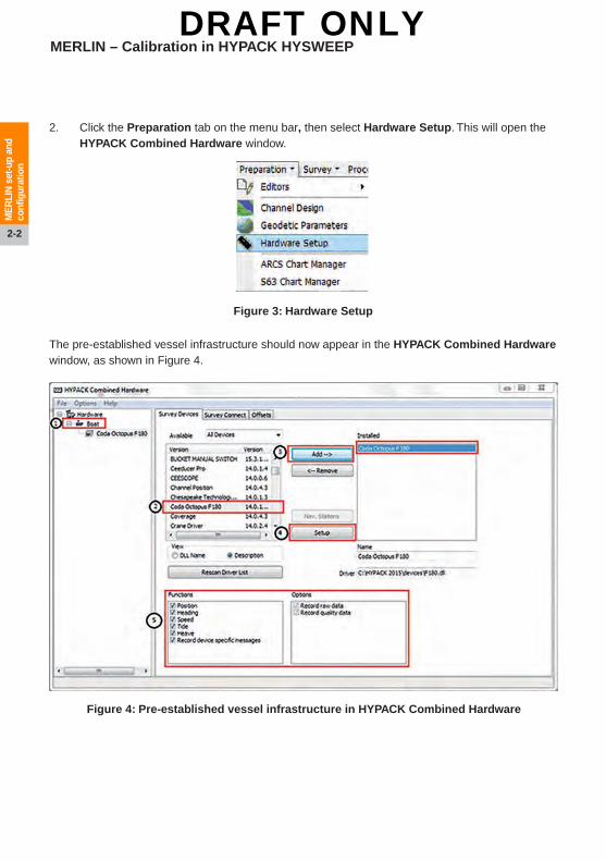
Figure 3: Hardware Setup
Figure 4: Pre-established vessel infrastructure in HYPACK Combined Hardware
2. Click the Preparation tab on the menu bar, then select Hardware Setup. This will open the HYPACK Combined Hardware window.
The pre-established vessel infrastructure should now appear in the HYPACK Combined Hardware window, as shown in Figure 4.
DRAFT ONLY

2-3
ME
RLI
N s
et-u
p an
d co
nfigu
ratio
n
Figure 5: HYSWEEP Survey configuration
2.2 Enable HYSWEEP
MERLIN operates in the HYSWEEP module, which needs to be included. If HYSWEEP is active you will see the HYSWEEP icon in the hardware section on the left. If this is not active, follow the steps below.
1. In the HYPACK Combined Hardware window, click the Hardware icon on the left. This will open the System window.
2. In the HYSWEEP Survey section, select the Include check box.
3. In the HYPACK Survey section, select the Show XYZ Files check box.
4. In the Synchronise Computer Clock section, make sure that the vessel IMU is the selected device (in this example it is the Coda Octopus F180).
DRAFT ONLY

MERLIN – Calibration in HYPACK HYSWEEP
2-4
ME
RLI
N s
et-u
p an
d co
nfigu
ratio
n
Figure 6: Add SLM driver
2.3 Merlin configuration
The following steps outline how to add and configure MERLIN into your pre-established vessel infrastructure project.
1. In the HYPACK Combined Hardware window, go to the Hardware section on the left and select HYSWEEP Survey.
2. Click the Manufacturer/Model tab in the centre window. From the list, select Renishaw SLM.
3. Click Add.
4. The Renishaw SLM will be displayed in the Installed list.
5. In the Name text box beneath the Installed list, rename to MERLIN 1. This will replace Renishaw SLM in the Installed list.
Note: Repeat steps 2 and 3 for a second MERLIN unit if required. When using a dual MERLIN set-up, uniquely identify each MERLIN unit added (for example, MERLIN 1 and MERLIN 2).
DRAFT ONLY
2-5
ME
RLI
N s
et-u
p an
d co
nfigu
ratio
n
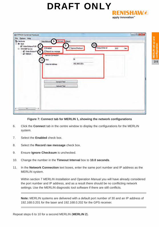
Figure 7: Connect tab for MERLIN 1, showing the network configurations
6. Click the Connect tab in the centre window to display the configurations for the MERLIN system.
7. Select the Enabled check box.
8. Select the Record raw message check box.
9. Ensure Ignore Checksum is unchecked.
10. Change the number in the Timeout Interval box to 10.0 seconds.
11. In the Network Connection text boxes, enter the same port number and IP address as the MERLIN system.
Within section 7 MERLIN Installation and Operation Manual you will have already considered the port number and IP address, and as a result there should be no conflicting network settings. Use the MERLIN diagnostic tool software if there are still conflicts.
Note: MERLIN systems are delivered with a default port number of 30 and an IP address of 192.168.0.201 for the laser and 192.168.0.202 for the GPS receiver.
Repeat steps 6 to 10 for a second MERLIN (MERLIN 2).
DRAFT ONLY
MERLIN – Calibration in HYPACK HYSWEEP
2-6
ME
RLI
N s
et-u
p an
d co
nfigu
ratio
n
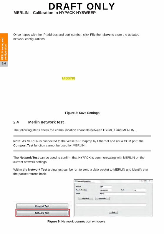
Figure 8: Save Settings
Once happy with the IP address and port number, click File then Save to store the updated network configurations.
2.4 Merlin network test
The following steps check the communication channels between HYPACK and MERLIN.
Note: As MERLIN is connected to the vessel’s PC/laptop by Ethernet and not a COM port, the Comport Test function cannot be used for MERLIN.
The Network Test can be used to confirm that HYPACK is communicating with MERLIN on the current network settings.
Within the Network Test a ping test can be run to send a data packet to MERLIN and identify that the packet returns back.
Figure 9: Network connection windows
MISSING
DRAFT ONLY

2-7
ME
RLI
N s
et-u
p an
d co
nfigu
ratio
n
Figure 10: Ping test – OK
Figure 11: UDP connection successful
To run a ping test:
1. Click the Network Test button.
2. Ensure that the Remote IP Address and Port are correct.
3. Click Ping Device.
4. Confirm that the test was successful, as shown in Figure 10, and then click Close.
If the ping device is unsuccessful, as shown in Figure 11, recheck the MERLIN settings. Make sure there is no IP address conflict with a second MERLIN unit or existing vessel hardware.
DRAFT ONLY

MERLIN – Calibration in HYPACK HYSWEEP
2-8
ME
RLI
N s
et-u
p an
d co
nfigu
ratio
n
Figure 12: Lever arm offsets
2.5 Merlin offsets
To calculate the position of MERLIN on the vessel co-ordinate frame, use the existing values of the vessel’s known reference points.
To understand the required measurements, see the MERLIN Installation and Operation Manual, section 5.9.1, “Lever arm offset measurement”; this outlines how to measure the lever arm with reference to the existing vessel infrastructure.
Note: Often there is an X, Y, Z value of 0,0,0 on the IMU. In HYPACK all Z measurements are positive downwards and measured from the waterline, meaning the traditional origin may have an existing Z value if it is not fixed at the waterline.
The MERLIN lever arm should have been measured during installation and should be entered into HYPACK as below.
1. In the HYPACK Combined Hardware window, go to the Hardware section on the left and select Merlin 1 within HYSWEEP Survey. Click the Offsets tab in the centre window.
2. In the Position section, enter the appropriate lever arm measurements in the Starboard, Forward and Vertical boxes.
3. Repeat steps 1 and 2 if a second MERLIN unit is being used, selecting the second MERLIN unit in HYSWEEP Survey on the left.
DRAFT ONLY

2-9
ME
RLI
N s
et-u
p an
d co
nfigu
ratio
n
Figure 13: MERLIN installed on a level surface
2.6 Merlin rotation
There are two ways to configure the MERLIN rotation offsets:
A. Enter approximate yaw, pitch and roll values, depending on MERLIN’s current horizontal and vertical orientation (see section 2.6.1, “MERLIN default values”). These can then be refined during a patch test calibration (see section 4, “Calibrating MERLIN via a patch test”).
B. Enter the calibration values as determined from the patch test (see section 4, “Calibrating MERLIN via a patch test”).
After entering the desired values, go to the File menu and select Save to finalise the equipment configuration. You can now exit the HYPACK Combined Hardware window. (Repeat steps A or B if a second MERLIN unit is being used.)
2.6.1 MERLIN default values
2.6.1.1 Roll
MERLIN should be mounted on what is deemed as a level surface “at rest”, i.e. parallel with the horizon.
The uncalibrated roll value should be entered as “0°”.
DRAFT ONLY

MERLIN – Calibration in HYPACK HYSWEEP
2-10
ME
RLI
N o
pera
tion
in H
YS
WE
EP
Figure 14: Pitch 0°
Figure 18: Yaw 0°
Figure 15: Pitch 15°
Figure 19: Yaw 15°
Figure 16: Pitch 30°
Figure 20: Yaw 30°
Figure 17: Pitch 45°
Figure 21: Yaw 45°
2.6.1.2 Pitch
The pitch angle value entered will depend on the vertical interval selected for the MERLIN system (see Figures 14–17).
The zero horizontal origin orientation will directly indicate the sign convention to be used for pitch: see Figure 22.
• For a zero horizontal origin orientation facing the STERN, enter a NEGATIVE pitch.
• For a zero horizontal origin orientation facing the BOW, enter a POSITIVE pitch.
2.6.1.3 Yaw (heading)
The yaw angle value entered will depend on the horizontal interval selected for the MERLIN system (see Figures 18-21).
The zero horizontal origin orientation will directly indicate the whole circle angle to be used for yaw: see Figure 22.
• For a zero horizontal origin orientation facing the STERN, enter “0”° yaw.
• Zero horizontal origin orientation facing BOW enter “180”° yaw.
• Calculate yaw for increments in a clockwise direction.
CAUTION: The information in this section, 2.6.1.3, “Yaw (heading)”, assumes that the MERLIN base plate 0° heading marker is orientated along the Y/Forward axis of the vessel – stern to bow. (See MERLIN installation and operation manual, section 5.3.2, “Recommended orientation of the flange plate.)
DRAFT ONLY

2-11
ME
RLI
N o
pera
tion
in H
YS
WE
EP
Fig
ure
22:
ME
RL
IN o
rien
tati
on
PIT
CH
BO
W YY X
ST
ER
N
PORT
STARBOARD
YAW
BO
W
Exa
mp
le A
• B
ow fa
cing
orie
ntat
ion
• 0°
inte
rval
YAW
= 1
80°+
0° =
180
°
Exa
mp
le B
• B
ow fa
cing
orie
ntat
ion
• 45
° in
terv
al (
to p
ort)
YAW
= 1
80°−
45°
= 1
35°
Exa
mp
le D
• S
tern
faci
ng o
rient
atio
n•
45°
inte
rval
(to
por
t)YA
W =
0°+
45°
= 4
5°
Exa
mp
le C
• B
ow fa
cing
orie
ntat
ion
• 45
° in
terv
al (
to s
tarb
oard
YAW
= 1
80°+
45°
= 2
25°
Exa
mp
le E
• S
tern
faci
ng o
rient
atio
n•
45°
inte
rval
(to
sta
rboa
rd)
YAW
= (
0°)3
60°−
45°
= 3
15°
Exa
mp
le F
• S
tern
faci
ng o
rient
atio
n•
0° in
terv
alYA
W =
0°+
0°
= 0
°
YY X
ST
ER
N
PORT
STARBOARD
BO
W F
AC
ING
• P
osi
tive
(+v
e) P
itch
val
ue
ST
ER
N F
AC
ING
• N
egat
ive
(−ve
) P
itch
val
ue
DRAFT ONLY

MERLIN – Calibration in HYPACK HYSWEEP
2-12
ME
RLI
N s
et-u
p an
d co
nfigu
ratio
n
This page is intentionally left blank.
DRAFT ONLY

3-1
ME
RLI
N o
pera
tion
in H
YS
WE
EP
Figure 23: HYPACK
Figure 24: HYPACK Survey and HYSWEEP survey
3 MERLIN operation in HYSWEEP
3.1 MERLIN control screen
Note: Historically, there has been a driver in HYSWEEP which operates a Renishaw Dynascan system. This can also operate a MERLIN system.
The control screen allows a user to adjust how MERLIN operates.
1. Open the main HYPACK window.
2. Click on the Survey tab and select HYPACK Survey and HYSWEEP Survey from the drop-down list.
DRAFT ONLY

MERLIN – Calibration in HYPACK HYSWEEP
3-2
ME
RLI
N o
pera
tion
in H
YS
WE
EP
Figure 25: Example layout of HYPACK Survey and HYSWEEP Survey window
Figure 26: Tools – MERLIN 1 Control
Both HYPACK and HYSWEEP will open.
3. From the HYSWEEP Survey window menu bar, click Tools. From the drop-down list select MERLIN 1 Control.
DRAFT ONLY
3-3
ME
RLI
N o
pera
tion
in H
YS
WE
EP
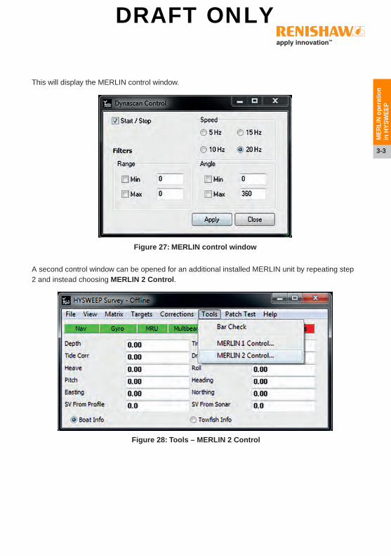
Figure 27: MERLIN control window
Figure 28: Tools – MERLIN 2 Control
This will display the MERLIN control window.
A second control window can be opened for an additional installed MERLIN unit by repeating step 2 and instead choosing MERLIN 2 Control.
DRAFT ONLY

MERLIN – Calibration in HYPACK HYSWEEP
3-4
ME
RLI
N o
pera
tion
in H
YS
WE
EP
3.2 Functionality
The following section describes how to use the Dynascan Controller to operate MERLIN.
Note: Clicking on the Apply button will activate all selected control features within the Control window. It is recommended that these are pre-configured at the start of any data acquisition, although it is possible to alter these during acquisition.
Start/Stop begins or stops the MERLIN laser rotation.
To start the laser, the Start/Stop check box should be checked. The laser will start only when Apply is clicked.
To stop the laser, uncheck the Start/Stop check box and click Apply.
Speed alters the speed of rotation of the MERLIN laser.
To change the speed before the laser is rotating, select the desired speed, make sure the Start/Stop box is checked, and then click Apply.
To change the speed whilst rotating, select the new desired speed then click the Apply button.
For most survey applications, select the maximum speed of 20 Hz.
Note: A slower speed of rotation will equate to a higher point density per 360° swath. If using a slower rotation speed, ensure the vessel velocity is reduced to compensate.
DRAFT ONLY

3-5
ME
RLI
N o
pera
tion
in H
YS
WE
EP
Range filters out data which is less than the set minimum and beyond the set maximum specified range.
To enable the Min and Max filters select the appropriate boxes and type in the desired filter ranges, then click the Apply button.
CAUTION: Any data filtered out will NOT be recorded. If in doubt, leave the range filter unchecked.
Angle filters out data between the minimum and maximum specified angle (see Figures 29 to 32 for examples in the Topographic Laser view).
Notes: • Minimum and maximum angles should be between 0° and
360°.• The 0° angle of MERLIN is orientated upwards (see
Figure 29 below). • The Topographical Laser window shown in Figures 29 to
32 can be opened, as shown in section 3.3.1, “Topographic Laser window”.
Figure 29: MERLIN angular rotation
DRAFT ONLY

MERLIN – Calibration in HYPACK HYSWEEP
3-6
ME
RLI
N o
pera
tion
in H
YS
WE
EP
Figure 31: 180° to 360° angular filter
Figure 32: 270° to 360° angular filter
Figure 30: 90° to 360° angular filter
DRAFT ONLY

3-7
ME
RLI
N o
pera
tion
in H
YS
WE
EP
3.3 Real-time data visualisation
There are two options to visualise real-time MERLIN data acquisition in HYSWEEP:
A. Topographic Laser window.
B. HYPACK Real Time Cloud window.
3.3.1 Topographic Laser window
The Topographic Laser window displays a 2D cross-section and relief view of real-time MERLIN laser data. To view the window:
1. In the HYSWEEP Survey menu bar click View, then select New Window. From the pop-up menu select Topographic Laser.
2. From the drop-down list select MERLIN 1.
3. In the Topographic Laser window menu bar click the icon (Toggle overhead view) to
toggle the 2D aerial/plan view of the laser data on and off.
Figure 33: Select Topographic Laser
Figure 34: Topographic Laser window
DRAFT ONLY

MERLIN – Calibration in HYPACK HYSWEEP
3-8
ME
RLI
N o
pera
tion
in H
YS
WE
EP
Note: Data from a second MERLIN unit can be displayed by following steps 1 and 2 from section 3.3.1, “Topographic Laser window”, making sure to select MERLIN 2 from the drop-down list in the second instance.
The parameters of the Topographic Laser window can be altered in the View Options window. To access this window, click the Display Options icon in the Topographic Laser window menu bar.
Figure 35: Aerial/plan view
Figure 36: Display Options icon
DRAFT ONLY

3-9
ME
RLI
N o
pera
tion
in H
YS
WE
EP
1. From the View Options menu, click the Ranges tab to open the window where you can adjust the extent of the Topographic Laser window:
(a) minimum depth
(b) maximum depth
(c) port and starboard offset limits.
Note: As HYPACK is typically used for below-waterline sensors, to orientate the Topographic Laser window correctly with respect to the real world, the maximum and minimum depth settings need to be inverted. For example, a minimum depth of −10 will show laser data up to 10 m above MERLIN). Equally, a maximum depth of 2.0 will show laser data below MERLIN by up to 2 m.
Figure 37: Topographic Laser range settings in the Ranges window
DRAFT ONLY

MERLIN – Calibration in HYPACK HYSWEEP
3-10
ME
RLI
N o
pera
tion
in H
YS
WE
EP
3. Click Coverage Map and ensure that the Show Topographic Coverage check box isselected. This will enable the laser data to be shown in the Matrix window.
4. Click Other tab and ensure that the Apply Heave, Pitch, Roll Corrections check box isselected. This will apply the heave, pitch and roll corrections to the laser data.
5. Click OK to close the View Options window.
Figure 38: Coverage Map settings
Figure 39: Other settings
DRAFT ONLY

3-11
ME
RLI
N o
pera
tion
in H
YS
WE
EP
3.3.2 HYPACK Real Time Cloud window
The Real Time Cloud window displays a 3D real-time view of MERLIN laser data during acquisition. The user can rotate, pan and zoom the view.
In the HYSWEEP Survey menu bar click View, then select HYPACK Real Time Cloud from the pop-up menu to open.
Figure 40: HYPACK Real Time Cloud
Figure 41: Real Time Cloud view
DRAFT ONLY

MERLIN – Calibration in HYPACK HYSWEEP
3-12
ME
RLI
N o
pera
tion
in H
YS
WE
EP
3.3.2.1 HYPACK Real Time Cloud tools
The following table is an extract from the HYPACK user manual and explains the tools and their functions in the Real Time Cloud window.
Table 1: Real Time Cloud tools
DRAFT ONLY

4-1
Cal
ibra
ting
ME
RLI
N
via
a pa
tch
test
4 Calibrating MERLIN via a patch test
The patch test requirements for the MERLIN laser scanner are similar to a multi-beam system patch test. The calibration process uses overlapping lines or “passes” of LiDAR data to compare the heading, roll and pitch offsets required to align the various passes.
To record accurate point cloud data during the acquisition stage of any project, MERLIN should be calibrated or recalibrated whenever:
• MERLIN has been uninstalled or reinstalled
• the relationship between the MERLIN unit and the IMU has changed (i.e., the location of the MERLIN unit or IMU has moved)
• MERLIN is used with a new or a recalibrated inertial measurement system.
4.1 Vessel-mounted calibration patch test
Note: Recommended practice for a patch test is to collect two pairs of passes for each offset to provide redundant data. The files should be split individually and named appropriately (for example, Heading_North1 and Heading_South1; Heading_North2 and Heading_South2).
4.1.1 Calibration site criteria
Note: Selection of a calibration site should be carefully considered in the planning stages.
The calibration site should be an “open sky’” environment with few surrounding high-rise structures and which can therefore provide good visibility to GNSS satellites and reduce the potential sources of multi-path where possible.
The site should offer coverage of a number of calibration features, for example (but not limited to): lampposts; telegraph or flag poles; industrial buildings; utility pylons; and flat scanable surfaces such as docks or pathways.
Examples of features that are useful to scan for calibration are shown in Figures 39-46.
Tall, straight and linear features are useful for calibrating the yaw (heading offset). They are also useful for calibrating the pitch offset, although the top of the features should ideally be unrestricted.
DRAFT ONLY

MERLIN – Calibration in HYPACK HYSWEEP
4-2
Cal
ibra
ting
ME
RLI
N
via
a pa
tch
test
Figure 42: Example for heading Figure 43: Example for yaw and pitch
Figure 44: Example for yaw and pitch
Figure 46: Cranes, if unmoving, can be used for heading and roll
Figure 45: The pitched building ceilings offer a feature for yaw calibration
Figure 47: If unmoving, these cranes can be used for yaw and the street lights for pitch
calibration
DRAFT ONLY

4-3
Cal
ibra
ting
ME
RLI
N
via
a pa
tch
test
4.1.2 Pre-calibration checks
A patch test requires the best quality GNSS/GPS conditions possible, to minimise any positional error on the calibration data. Efficient mission planning will help to identify a time frame where there is a good quality GNSS satellite geometry. A low PDOP (position dilution of precision) value will correlate to a good satellite geometry. Use mission planning and/or RTK (Real Time Kinematic) or post-processing to improve the quality of the vessel’s trajectory.
4.2 Trailer-mounted onshore calibration
For smaller vessels, an onshore patch test may be possible by mounting the vessel on a trailer and using an open-sky location (such as a supermarket car park or parking lot) with suitable calibration features.
Figure 48: This platform contains struts for yaw and posts for pitch
Figure 49: This dock offers tall, linear posts for pitch calibration
Figure 50: Trailer-mounted onshore calibration
DRAFT ONLY

MERLIN – Calibration in HYPACK HYSWEEP
4-4
Cal
ibra
ting
ME
RLI
N
via
a pa
tch
test
4.3 Patch test methodology
Note: It is recommended to capture features at a distance of 30 m to 50 m for calibration.
4.3.1 Yaw
Travel past a tall, linear feature – for example, a lamppost, telegraph pole or a flagpole. Pass by twice, both times passing in the same direction. If possible, travel past either side of the feature.
4.3.2 Roll
Travel parallel to a flat surface – for example, a towpath, road or car park. Pass by twice, each time travelling in the opposite direction: for example, north to south; then south to north.
Pole
First pass
User-defined line for HEADING calibration
Scan lines from both passes
Second pass
Pole
Indication in swath view if HEADING is misaligned
Ground
Indication in swath view if ROLL is misaligned
Angular error
Figure 51: Yaw calibration routine
Figure 52: Roll calibration routine
First pass direction of travel
User-defined line for ROLL calibration
Scan lines from both passes
Second pass direction of travel
DRAFT ONLY

4-5
Cal
ibra
ting
ME
RLI
N
via
a pa
tch
test
4.3.3 Pitch
Pass by a tall linear feature – for example, a lamppost, telegraph pole or a flagpole. Pass by twice: however, each pass must be made in the opposite direction.
4.4 HYPACK data logging
The laser data can be logged in the HYPACK Survey window by using the logging button to start and stop each line of data.
The laser data will be recorded as an HSX file with an accompanying RAW file. The HSX file can then be opened in the HYSWEEP Editor (64 bit) for processing (see section 5, “Calibrating MERLIN in HYPACK”).
Once the dataset for the patch test has been collected, close the HYPACK Survey and HYSWEEP Survey window: click the Logging icon, then select Exit from the HYPACK Survey toolbar.
The logged data is stored in the Project folder. To access it, click File and select Windows Explorer from the toolbar of the main HYPACK window (see Figure 2). This will open the Project folder structure. The logged data files are stored in the Raw folder.
Pole
First pass
User-defined line for PITCH calibration
Scan lines from both passes
Second pass
Pole
Indication in swath view if PITCH is misaligned
Ground
Angular error
Figure 53: Pitch calibration routine
Figure 54: HYPACK Survey main toolbar
Figure 55: Logging icon
DRAFT ONLY

MERLIN – Calibration in HYPACK HYSWEEP
4-6
Cal
ibra
ting
ME
RLI
N
via
a pa
tch
test
This page is intentionally left blank.
DRAFT ONLY

5-1
Cal
ibra
ting
ME
RLI
N
in H
YPA
CK
5 Calibrating MERLIN in HYPACK
5.1 Importing the patch test data
Open the main HYPACK window.
From the top menu bar click HYSWEEP.
Select either HYSWEEP Editor or HYSWEEP Editor (64-bit).
Note: Use the 64-bit editor only if the computer is running a 64-bit operating system.
The MBMAX64 window will open. From the menu bar click File, then select Load Survey.
Figure 56: HYPACK
Figure 58: Load Survey
Figure 57: HYSWEEP Editor (64 bit)
DRAFT ONLY

MERLIN – Calibration in HYPACK HYSWEEP
5-2
Cal
ibra
ting
ME
RLI
N
in H
YPA
CK
Select the correct .LOG file from the Raw folder of the project of the acquired calibration data, and click Open (see section , “HYPACK data logging”).
The Catalog window will open. Click on the files required to highlight them, and then click Select. (To select multiple files, hold down CTRL, click on the appropriate files, and then click Select. If all files are required, click Select All.)
Figure 59: Open HYPACK Catalog (.LOG)
Figure 60: Catalog window
DRAFT ONLY

5-3
Cal
ibra
ting
ME
RLI
N
in H
YPA
CK
Once all files collected for the Patch test are selected, click on the Select button. The Read Parameters window will open. Click Survey, then select the Elevation Mode radio button.
In the Matrix section, click Edit. The Matrix Settings window will open.
In the Cells section select Auto Cell Size, or manually enter a cell size in the Size text entry box. Once either is selected, click OK to return to the Read Parameters window
Note: Large surveys displayed at a smaller cell size will take longer to load and refresh.
Figure 61: Read Parameters – survey window
Figure 62: Matrix Settings window
DRAFT ONLY

MERLIN – Calibration in HYPACK HYSWEEP
5-4
Cal
ibra
ting
ME
RLI
N
in H
YPA
CK
Click Devices.
Click the Edit button (which is beneath Sonar Head 2), and the Device Offsets window will open (see Figure 64.)
Figure 63: Read Parameters – Devices tab
DRAFT ONLY

5-5
Cal
ibra
ting
ME
RLI
N
in H
YPA
CK
Confirm all installation lever arm offsets are correct and ensure that Renishaw SLM is selected in the Sonar text box. Click OK to return to the Read Parameters window.
CAUTION: Ensure the latency is 0.000.
In the Patch Test section, click Edit. The Patch Tests Offsets window will open.
CAUTION: Ensure the latency is 0.000.
Ensure the yaw, pitch and roll values are the approximate values used for the patch test (see section 2.6, “Merlin offsets”).
Figure 64: Device Offsets window
Figure 65: Patch Test Offsets window
DRAFT ONLY

MERLIN – Calibration in HYPACK HYSWEEP
5-6
Cal
ibra
ting
ME
RLI
N
in H
YPA
CK
Notes: • If different combinations of horizontal and vertical MERLIN orientations were used in a survey,
the appropriate offset values need to be applied to the correct HSX files.• To set the offsets for the first batch of files, select the required HSX files from the left-hand
column of the Read Parameters window. In the Patch Test section, click Edit. In the Patch Test Offsets window (Figure 66), enter the offsets as required and then click OK.
• To enter the offsets for the next batch of files, which have a different orientation, select the relevant HSX files from the left-hand column of the Read Parameters window. In the Patch Test section, click Edit, and type in the new offset values. Then click OK.
• The new values will then be displayed in the Patch Test section.
When the Device offsets and Patch Test offsets are correct in the Read Parameters window, click OK and the files will be loaded into the Editor.
Figure 66: Batch parameter editing
DRAFT ONLY

5-7
Cal
ibra
ting
ME
RLI
N
in H
YPA
CK
When the Device offsets and Patch Test offsets are correct in the Read Parameters window, click OK and the files will be loaded into the Editor , as shown in the left‑hand window in Figure 67.
Figure 67: The MBMAX64 window
DRAFT ONLY

MERLIN – Calibration in HYPACK HYSWEEP
5-8
Cal
ibra
ting
ME
RLI
N
in H
YPA
CK
5.2 MBMAX64 Editor
5.2.1 Loading data
In HYSWEEP Editor, click File and select Stage 2 (Depth Editing) from the drop-down menu.
Stage 2 (Depth Editing) will import the laser data into the Survey Matrix.
Note: To edit any of the installation parameters during processing, click File and select Read Parameters. Change the settings as required and then click the Update Devices button (see section 5.1, “Importing the patch test data”).
5.2.2 MBMAX64 tool bar
In the MBMAX64 tool bar, set the following parameters:
• In the Selection window, select Average from the drop-down menu.
• In the Style window, select Colour Model from the drop-down menu.
These settings will help to distinguish individual features in the matrix for calibration.
Note: An alternative would be to set the Selection to Z Range. This will help locate tall features, such as lampposts or buildings, which will colour features according to height above ground.
• In the Show options check boxes, always ensure Cells is selected.
• Use the icons in the tool bar to select either a map view or profile view .
Figure 68: MBMAX64 tool bar options
Figure 69: Depth Editing
DRAFT ONLY

5-9
Cal
ibra
ting
ME
RLI
N
in H
YPA
CK
• Users can also either:
(a) take a cross-section using the A-B Cross Section tool , or
(b) view a 3D cloud view using the Cloud Pop-up tool .
5.2.3 Data management
To display only the files that are of interest, click Survey Files in the MBMAX64 window.
Ensure the Draw Selected Files Only check box is selected. Highlight only the required files from the list.
To delete a pass, highlight it in the list and click the Remove from survey cross.
Figure 70: Draw Selected Files Only
Figure 72: ‘Remove from survey’ cross
Figure 71: Select roll passes
DRAFT ONLY

MERLIN – Calibration in HYPACK HYSWEEP
5-10
Cal
ibra
ting
ME
RLI
N
in H
YPA
CK
5.2.4 Patch test editor
Click on the A-B Cross Section and Patch Test tool to select it.
In the Survey Matrix window (Figure 67) identify those features that are to be used for the appropriate calibration (yaw, roll and pitch, as described in section 5.3, “Calibrating roll”, section 5.4, “Calibrating yaw”, and section 5.5, “Calibrating pitch”). Click and drag the A-B Cross Section tool over the feature(s).
The A-B Cross Section window will pop up and display the feature in a profile view.
In the Patch Test section under Select there are options to adjust the roll, pitch and yaw using the Automated Test process.
Figure 73: A-B Cross Section and Patch Test tool
Figure 74: A-B Cross Section and Patch Test pop-up window
DRAFT ONLY

5-11
Cal
ibra
ting
ME
RLI
N
in H
YPA
CK
5.3 Calibrating roll
1. From the list of files available in the MBMAX64 window, select the files from the patch test that were collected for calibrating the roll offset. Follow the steps detailed in section 5.2.3, “Data management”.
2. Use the A-B Cross Section tool to drag and draw a section across a suitable flat surface or a tall feature that has been captured in two opposing directions. Follow the steps detailed in section 5.2.4, “Patch test editor”.
3. In the A-B Cross Section and Patch Test window, ensure the Roll check box is selected in the Select options. To start the calibration, select Coarse for Choose Step Size and then click Start Roll Test.
Note: The automated roll adjustment will examine the cross-section and determine an approximate offset that the algorithm calculates would bring the passes into alignment.
4. Use the Step – or Step + buttons to manually improve the adjustment.
This will decrease or increase the steps until the passes appear to be aligned as close as possible. This will decrease or increase the roll offset. Continue to adjust until the passes
Figure 75: Roll – coarse step size
Figure 76: Increasing or decreasing the steps manually
DRAFT ONLY

MERLIN – Calibration in HYPACK HYSWEEP
5-12
Cal
ibra
ting
ME
RLI
N
in H
YPA
CK
shown in the A-B Cross section window are aligned (see Figure 77 and Figure 78). Once approximately aligned, click Test OK.
Figure 77: Example of uncalibrated roll
Figure 78: Example of calibrated roll
DRAFT ONLY

5-13
Cal
ibra
ting
ME
RLI
N
in H
YPA
CK
5. Select Medium from Choose Step Size.
Repeat the process as described in step 4 above, adjusting the Step until the passes are as closely aligned as possible. Once satisfied, apply the adjustment by clicking Test OK.
6. Select Fine roll from Choose Step Step Size.
Repeat the process as described in step 4 above, adjusting as required. Once satisfied, apply the adjustment by clicking Test OK.
The final roll value will now be computed and displayed in the Final Offset text box. Click Update Config Files… to apply the final roll offset to the configuration files from the patch test survey.
7. Close the A-B Cross Section window.
Figure 79: Roll – medium step size
Figure 80: Roll – fine step size
Figure 81: Roll test OK
DRAFT ONLY

MERLIN – Calibration in HYPACK HYSWEEP
5-14
Cal
ibra
ting
ME
RLI
N
in H
YPA
CK
8. In the MBMAX64 window, the Update Devices button should be highlighted red: click it to apply the new roll value to the loaded data on screen.
9. Check the roll value is correct across the dataset by taking cross-sections along flat surfaces from different locations in the patch test survey dataset using the A-B Cross Section tool (see section 5.2.4, “Patch test editor”).
10. To adjust the roll offset, take a cross-section using the A-B Cross Section tool. In the pop-up window, repeat the process of starting roll tests of different step sizes (coarse, medium or fine) until satisfied with the new roll offset, as illustrated in Figure 78.
5.4 Calibrating yaw
1. From the list of files available in the MBMAX64 window, select the files from the patch test that were collected for calibrating the yaw offset. Follow the steps detailed in section 5.2.3, “Data management”.
2. Use the A-B Cross Section tool to drag and draw a section across a tall, linear feature, such as a pole or post, that has been captured in the same direction. Follow the steps detailed in section 5.2.4, “Patch test editor”.
CAUTION: The feature may not yet be aligned at the top, as this is calibrated through a pitch adjustment. However, when adjusting the yaw, the feature should be aligned at the base of the feature.
Figure 82: Update Devices button
DRAFT ONLY

5-15
Cal
ibra
ting
ME
RLI
N
in H
YPA
CK
3. In the A-B Cross Section and Patch Test window, ensure the Yaw check box is selected in the Select options. To start the calibration, select Coarse from Choose Step Size and then click Start Yaw Test.
Note: The automated yaw adjustment will examine the cross-section and determine an approximate offset that the algorithm calculates would bring the passes into alignment.
4. Use the Step – or Step + buttons to manually improve the adjustment.
This will decrease or increase the steps until the passes appear to be aligned as close as possible.
Figure 83: Yaw – coarse step size
Figure 84: Increasing or decreasing the steps
DRAFT ONLY

MERLIN – Calibration in HYPACK HYSWEEP
5-16
Cal
ibra
ting
ME
RLI
N
in H
YPA
CK
Once approximately aligned, click Test OK.
5. Select Medium from Choose Step Size.
Repeat the process as described in step 4 above, adjusting the Step until the passes are as closely aligned as possible. Once satisfied, apply the adjustment by clicking Test OK.
Figure 85: Example of uncalibrated yaw
Figure 86: Example of calibrated yaw
Figure 87: Yaw – medium step size
DRAFT ONLY

5-17
Cal
ibra
ting
ME
RLI
N
in H
YPA
CK
6. Select Fine from Choose Step Size.
Repeat the process as described in step 4 above, adjusting as required. Once satisfied, apply the adjustment by clicking Test OK.
The final yaw value will now be computed and displayed in the Final Offset text box. Click Update Config Files… to apply the final yaw offset to the configuration files from the patch test survey.
7. Close the A-B Cross Section window.
8. In the MBMAX64 window, the Update Devices button should be highlighted red: click it to apply the new yaw value to the loaded data on screen.
9. Check the yaw value is correct across the dataset by taking cross-sections along flat surfaces from different locations in the Patch Test survey dataset using the A-B Cross Section tool.
Figure 88: Yaw – fine step size
Figure 89: Yaw test OK
Figure 90: Update Devices button
DRAFT ONLY

MERLIN – Calibration in HYPACK HYSWEEP
5-18
Cal
ibra
ting
ME
RLI
N
in H
YPA
CK
5.5 Calibrating pitch
1. From the list of files available in the MBMAX64 window, select the files from the patch test that were collected for calibrating the pitch offset. Follow the steps detailed in section , “Data management”.
2. Use the A-B Cross Section tool to drag and draw a section across a tall, linear feature, such as a pole or post, that has been captured in opposite directions. Follow the steps detailed in section , “Patch test editor”.
3. In the A-B Cross Section and Patch Test window, ensure the Pitch check box is selected in the Select options. To start the calibration, select Coarse from Choose Step Size and then click Start Pitch Test.
Note: The automated pitch adjustment will examine the cross-section and determine an approximate offset that the algorithm calculates would bring the passes into alignment.
4. Use the Step – or Step + buttons to manually improve the adjustment.
This will decrease or increase the steps until the passes appear to be aligned as close as possible.
Figure 91: Pitch – coarse step size
Figure 92: Increasing or decreasing the steps
DRAFT ONLY

5-19
Cal
ibra
ting
ME
RLI
N
in H
YPA
CK
Once approximately aligned, click Test OK.
5. Select Medium from Choose Step Size.
Repeat the process as described in step 4 above, adjusting the Step until the passes are as closely aligned as possible. Once satisfied, apply the adjustment by clicking Test OK.
6. Select Fine from Choose Step Size.
Repeat the process as described in step 4 above, adjusting as required. Once satisfied, apply the adjustment by clicking Test OK.
Figure 93: Example of uncalibrated pitch
Figure 94: Example of calibrated pitch
Figure 95: Pitch – medium step size
Figure 96: Pitch – fine step size
DRAFT ONLY

MERLIN – Calibration in HYPACK HYSWEEP
5-20
Cal
ibra
ting
ME
RLI
N
in H
YPA
CK
The final pitch value will now be computed and displayed in the Final Offset text box. Click Update Config Files… to apply the final pitch offset to the configuration files from the patch test survey.
7. Close the A-B Cross Section window.
8. In the MBMAX64 window, the Update Devices button should be highlighted red: click it to apply the new pitch value to the loaded data on screen.
9. Check the pitch value is correct across the dataset by taking cross-sections along flat surfaces from different locations in the patch test survey dataset using the A-B Cross Section tool.
Figure 97: Pitch test OK
Figure 98: Update Devices button
DRAFT ONLY

5-21
Cal
ibra
ting
ME
RLI
N
in H
YPA
CK
5.6 QA check
Once roll, pitch and yaw for MERLIN have been calibrated, ensure that all the HSX files from the patch test survey have been updated with the new offsets.
To check this, open the HYPACK Combined Hardware window, select MERLIN 1 from the HYSWEEP Survey list and click the Offsets tab. The rotation values should have been updated with the new offsets from the patch test.
Note: Make a note of the new values for use in upcoming survey work.
To visualise the data in a 3D model select the Cloud Pop-up tool . Then drag a box around the
area of data you want to visualise in the Survey Matrix (see Figure 69).
Ensure that all areas of the calibration site appear correctly aligned.
Figure 99: Check patch test offsets
DRAFT ONLY

MERLIN – Calibration in HYPACK HYSWEEP
5-22
Cal
ibra
ting
ME
RLI
N
in H
YPA
CK
This page is intentionally left blank.
DRAFT ONLY

DRAFT ONLY

Renishaw plc
Redwood House, Northminster Business Park, York, North Yorkshire, YO26 6QR, UK
T +44 (0)1904 736736 F +44 (0)1904 736701 E [email protected]
www.renishaw.com
For worldwide contact details, visit www.renishaw.com/contact
*H-9931-9503-01*
DRAFT ONLY


![2013 04 29 Post training Portland pke low - Norbit · PDF file29#April,#2013# Prac%cal'Mul%beam'Training' for'Hydrographers# ... 8 So]ware#;#Hypack#Hysweep,#CARIS#g##](https://static.documents.pub/doc/80x56/5a7febdd7f8b9a682c8be259/2013-04-29-post-training-portland-pke-low-norbit-2013-praccalmulbeamtraining.jpg)


