+ All Categories
Home > Documents > Mesoporous gold electrodes for sensors based on ...

Mesoporous gold electrodes for sensors based on ...

Date post: 16-Mar-2022
Category:
Upload: others
View: 2 times
Download: 0 times
Share this document with a friend
21
Mesoporous gold electrodes for sensors based on electrochemical double layer capacitance Alessia Mortari ‡§ , Abbas Maaroof , Donald Martin and Michael B. Cortie Institute for Nanoscale Technology, University of Technology Sydney, Australia § On leave from the Department of Analytical Chemistry, Lund University, Sweden ABSTRACT The use of mesoporous gold as electrode material for measurement of electrochemical capacitance is investigated. The electrodes possess a pore size in the range of 10 to 30 nm and are prepared by de-alloying films of AuAl x , where x2. Analyses conducted with X-ray photoelectron spectra (XPS) show that their surfaces are essentially pure gold, with only traces of aluminium remaining. The electrodes show near-ideal capacitor behaviour under both cyclic voltammetry and potential-step conditions. The higher capacitance of the mesoporous electrodes leads to a better dynamic range in potential-step experiments, resulting in improved accuracy of measurement. The sensitivity of the new material as a capacitive sensor is demonstrated in a milk fouling experiment, and is improved by up to 30 times compared to the control sample of ordinary planar gold. We propose that the use of mesoporous gold electrodes offer a convenient way to sensitively and accurately amplify the capacitance signal of an electrochemical sensor. KEYWORDS: double layer capacitance, capacitive sensor, mesoporous gold, nanoporous gold, accuracy, sensitivity. Institute for Nanoscale Technology, University of Technology Sydney, PO Box 123, Broadway, NSW 2007, Australia; ph. +61-2-9514-2208; fax +61-2-9514-7553; e-mail: [email protected]
Transcript

Mesoporous gold electrodes for sensors based on

electrochemical double layer capacitance

Alessia Mortari‡§

, Abbas Maaroof‡, Donald Martin

‡ and Michael B. Cortie

‡Institute for Nanoscale Technology, University of Technology Sydney, Australia

§On leave from the Department of Analytical Chemistry, Lund University, Sweden

ABSTRACT

The use of mesoporous gold as electrode material for measurement of electrochemical capacitance is

investigated. The electrodes possess a pore size in the range of 10 to 30 nm and are prepared by de-alloying

films of AuAlx , where x≥2. Analyses conducted with X-ray photoelectron spectra (XPS) show that their

surfaces are essentially pure gold, with only traces of aluminium remaining. The electrodes show near-ideal

capacitor behaviour under both cyclic voltammetry and potential-step conditions. The higher capacitance of

the mesoporous electrodes leads to a better dynamic range in potential-step experiments, resulting in

improved accuracy of measurement. The sensitivity of the new material as a capacitive sensor is

demonstrated in a milk fouling experiment, and is improved by up to 30 times compared to the control

sample of ordinary planar gold. We propose that the use of mesoporous gold electrodes offer a convenient

way to sensitively and accurately amplify the capacitance signal of an electrochemical sensor.

KEYWORDS: double layer capacitance, capacitive sensor, mesoporous gold, nanoporous gold, accuracy,

sensitivity.

Institute for Nanoscale Technology, University of Technology Sydney,

PO Box 123, Broadway, NSW 2007, Australia; ph. +61-2-9514-2208; fax +61-2-9514-7553; e-mail:

[email protected]

2

1. Introduction

Electrochemical capacitive sensors have been proposed or used for many different applications [1, 2] and

can serve as a transducting platform on which to design diverse biosensors [3]. In general, emphasis in this

field has been placed on developing new signal processing systems [4, 5] and sensor interfaces [4, 6, 7] in

order to increase the accuracy of capacitance measurement. Nearly all of the existing applications are based

on planar or cylindrical metallic electrodes. However, porous or mesoporous metallic structures can also be

envisaged for electrodes. Porous metallic surfaces produced by electrodeposition , de-alloying or colloidal

aggregation have interesting new properties [8-10] and have found practical or potential applications as

electrodes in electrochemical devices such as super-capacitors [11, 12] and as sensor substrates for optical

techniques such as surface enhanced Raman spectroscopy (SERS) or surface plasmon spectroscopy, e.g. [13,

14]. Mesoporous metal electrodes produced by de-alloying can have particularly high specific surface areas,

in excess of 2 m2/g, and possess tortuous and semi-enclosed pores. The high surface area leads directly to an

enhanced electrochemical double layer capacitance, since the capacitance, C, is proportional to the surface

area, S, via the standard relationship:

C =εε0S

d (1)

where ε is the dielectric constant of the medium, ε0 is the permeability of free space and d the inter-plate

distance. In the present instance d can be taken as the thickness of the electrical double layer developed

around the electrodes.

Compared to a planar gold electrode of same nominal area, mesoporous gold (also known as Raney gold [8,

15], or nanoporous gold [16]) has a significantly increased specific surface area and therefore electrolytic

capacitance [12]. Like planar gold it can be readily produced in thin films [17] but its advantage in respect of

capacitance appears not to have been exploited yet in sensor design. Here we propose that the use of this

material in electrodes could lead to the development of capacitive sensors of improved sensitivity and

accuracy. To address this hypothesis, two different kinds of mesoporous gold were developed and compared

to each other and to conventional sputtered gold electrodes. The microstructure, chemical composition and

electrochemical stability of the gold coatings was characterized, while the electrochemical double-layer

3

formation was studied using cyclic voltammetry. The capacitance values were independently determined

using potential step experiments, and cyclic voltammetry. Finally, to verify the sensitivity of the experimental

electrodes, the proteinaceous fouling that occurs on surfaces immersed in milk was used as a dynamic test.

2. Experimental materials and methods

2.1 Preparation of mesoporous metal films

Mesoporous gold films were made by de-alloying thin films comprised either of the intermetallic compound

AuAl2, or very fine-scale mixtures of it with Al. The starting films were prepared by co-depositing the

elements using high vacuum direct current magnetron sputtering, applied onto glass microscope slides

through a 15 x 15 mm hole in a thin mica mask. The sputtering targets of Au and Al were 99.999% pure discs

(50 mm diameter) placed 150 mm away from the substrate. The base pressure was better than ~1x10⁻⁴

Pa

(~10-6

torr) while sputtering was carried out in the presence of flowing Ar at a pressure of 0.25 Pa (2x10⁻³

torr) with a 3kV 10W radio frequency (RF) biased substrate. To ensure good homogeneity and crystallinity,

the substrate was heated to 400°C during deposition. The aluminum was subsequently removed from the

compound by immersing the films in 0.2 M aqueous NaOH solution for about one minute.

Three types of sample are discussed in this paper. They are designated ‘100mesoAu’, consisting of a

mesoporous layer of Au that is nominally 100 nm thick and deposited as AuAl2, ‘5050mesoAu’, a coating

consisting of 50 nm of solid gold on top of which was 50 nm of mesoporous gold deposited as 1Au:4Al (i.e.

Al-rich), and ‘sAu’, the comparator sample, which consisted of 100 nm of solid gold.

The electrodes were stored under high purity water in order to minimize surface oxidation and non-specific

adsorption of particles such as dust, which we found would otherwise inactivate and/or passivate the metal.

The electrodes were used within two days of de-alloying.

The In-Lens imaging mode of a Zeiss Supra 55VP scanning electron microscope was used to study the

morphology and cross sections of the films. The particular samples studied in this instrument were deposited

4

onto a silicon substrate (rather than onto glass) in order to ensure that they were electrically grounded in the

microscope. The XPS data shown were obtained using Al kα radiation.

2.2 Capacitance measurement

The electrochemical double layer capacitance developed on the electrodes was measured by two instruments,

a cyclic voltammeter, and a custom-built apparatus that applied a potential step to the electrode.

The cyclic voltammetric measurements were performed on an eDAQ potentiostat, using platinum foil as

auxiliary electrode, Ag/AgCl as reference electrode and one of the gold samples under investigation as

working electrode. Capacitance was calculated from current-potential plots by applying the relation:

i = vC (2)

where i is the current, v the scan rate and C the capacitance. The cyclic voltammetry experiments were

executed under diffusion control.

The custom-built apparatus applied a square wave potential to the electrodes using a constant voltage power

supply switched through a reed relay driven by a programmable voltage source (Figure 1). The applied square

wave potential cycled between 60 mV for 3 seconds followed by 3 seconds at 0 mV. The voltage transients in

the test cell were monitored using a LabJack U12 (LabJack Corporation, www.labjack.com) analogue-to-

digital converter interfaced to a computer at an 8 kHz data acquisition rate. A counter-electrode of Pt foil was

used. Capacitance was extracted from the data using custom-written software, which exploited the RC-

induced decay characteristics of the circuit through the expression:

Vt = V0

−t

RC (3)

where Vt is the recorded discharging potential at time t, V0 is the applied potential and R is the resistance of

the circuit (a 8.2 kΩ resistor was used as an external resistance). The software extracted all data with

transient voltages in a user-defined input window (for example, between 60 and 45 mV) and the capacitance

was obtained over this range by applying regression on equation 3. Data sets were highly reproducible and

produced well-defined semi-logarithmic linear plots of ln(E) vs t (see Results and Discussion).

5

2.3 Electrolytes and test solutions

Potassium phosphate monobasic (H2KPO4, Product no. 60220), sodium phosphate dibasic dihydrate

(HNa2PO4·2H2O, Product no. 71644) and potassium chlorate (KCl, Product no. P-3911) were used as-

purchased from Sigma-Aldrich to constitute a Phosphate Buffered Saline (PBS) containing 5·10-3

M

phosphate buffer pH 7.5 and 0.1 M KCl. All the reagents were of analytical grade and solutions were, if not

otherwise specified, prepared using analytical-grade water, produced using a Milli-Q Plus Millipore Water

System (Millipore Australia Pty Ltd). Fresh, pasteurized milk was purchased from a convenience store.

3. Results and discussion

3.1 Microstructure and composition of coatings

The surface of both types of mesoporous coating was characterized by fine pores (Figures 2a and 2b) and it

was also clear that the surface of the 5050mesoAu sample was considerably more uneven than that of the

100mesoAu sample. This effect was common to Al-rich samples and is a consequence of the greater volume

of material removed in those cases by de-alloying. The pores in the 100mesoAu samples were roughly

circular in cross section, with openings varying between about 10 and 30 nm in diameter. This is in

congruence with pore sizes obtained in previous work [12, 17]. However, those of the 5050mesoAu sample,

while consistently about 10 nm across at their narrowest, were elongated and vermicular (worm-like) in

nature. XPS analyses of the surfaces confirmed that they were of elemental Au, with some indications of Al

and C contamination (Figure 3).

3.2 Stability study

Non-specific adsorption of particles such as dust and surface oxidation could inactivate and/or passivate

metal surfaces. Therefore the capacitance of the three electrode types was also investigated as a function of

time (Figure 4). All three samples showed a considerable loss of capacitance over the course of several days.

Consequently, in order to minimize the inactivation processes, the electrodes were stored under high purity

water and used within three days.

6

3.3 Cyclic voltammetry and electrochemical double layer formation

The cyclic voltammetry experiments were performed with the purpose of investigating and comparing

formation, development and detection of the electrical double layer on the samples 100mesoAu, 5050mesoAu

and the control sample sAu. The gold electrodes were immersed in PBS and cycled in the potential window

of interest from 300 to 100 mV and at different scan rates, from 2 to 100 mV/sec. It was necessary to reduce

the potential window since the thin mesoporous gold layer peeled off the glass support if held at potentials

higher then 500 mV. The potential window was first scanned five times to ensure removal of bubbles and

homogeneous diffusion of the buffer ions through the three-dimensional structure to the surface of the gold

electrodes. The results presented correspond to the fifth cycle of every measurement. The voltammograms

recorded with 100mesoAu (Figure 5a) exhibited a rectangular shape, especially at slow sweep-rate. This is

the characteristic of an ideal capacitor and indicates an unopposed electrolyte motion in the pores. In

voltammograms of near-rectangular shape the steepness of the charging process at the switching potential is

small. The steepness is generally defined by the capacitance time constant and the equivalent series resistance

(ESR), where ESR is formed by the contributions of electrode resistance, bulk electrolyte resistance and the

electrolyte resistance in pores. It is reported that small time constants and low resistances are typical of

mesoporous structures of conducting materials such as carbon [18, 19]. The voltammogram profiles gradually

tilted with the increase of the scan rate, which indicates an increased ohmic resistance of the electrolyte in the

pores during fast processes. The same behaviour was observed with 5050mesoAu (Figure 5b); however, the

current developed during the charging and discharging processes was smaller. In contrast, the

voltammograms for sAu exhibited a depressed shape, and the profile was distorted at the slowest sweep rate

(Figure 5c). In this case, the high time constant was mainly due to the resistance of the thin gold layer, which

leads to the loss of capacitance at slow scan rates.

The relation between capacitance and scan rate provides an interesting insight into the behaviour of the

materials (Figure 6). The sample sAu showed little influence of scan rate on the capacitance (rates from 10 to

100 mV/sec) and the capacitance was estimated to be about 1·10-4

F/cm2. Samples 100mesoAu and

5050mesoAu showed two different behaviours in the resulting charging and discharging curves: a first part

where the capacitance increased with the scan rate and a second part where the capacitance hardly changed

with the increase of scan rate. In the second part of the curves, which corresponds approximately to the sAu

7

scan rate window, the same tendency as sAu was displayed and a stable relation between capacitance and

sweep rate was observed. The capacitance values in those cases were calculated to be about 1.3·10-3

F/cm2

and 1.1·10-3

F/cm2 for 100mesoAu and 5050mesoAu respectively (the surface area corresponds to the planar

surface area of the electrodes). Those capacitance values are an order of magnitude greater than the ordinary

gold sAu sample. On the other hand, in the first part of the 100mesoAu and 5050mesoAu curves, from 2 to 10

mV/sec, the capacitance increased with the increase of sweep rate. Consequentially there must be an

additional or increased limiting factor contributing to the decrease of capacitance at slow scan rates. Ion

diffusion in pores is favoured at slow scan rate, while the resistance of the electrode is an intrinsic

characteristic of the material and is unaffected by scan rate. At the same time, the diffusion of bulk ions

should be constant at the experimental concentration (0.1 M KCl supporting electrolyte in 5 mM phosphate

buffer pH 7.5). To verify the effect of the bulk ions diffusion an experiment was run with 10 times higher

electrolyte concentration. Under these experimental conditions, the capacitance increased at slow scan rates

(results not shown). Consequentially it was deduced that a low ionic concentration was the factor limiting the

development of capacitance at the slower scan rates of Figure 6. It is likely that the phenomenon is

exacerbated by the impressive increase of real surface within the three dimensional spongy structure of the

mesoporous electrodes.

It should be also noted that the charging and discharging processes showed different capacitance values. The

disparities may be due to the different diffusion coefficients of the buffer cations and anions. Evidently, use

of 100mesoAu and 5050mesoAu electrodes allowed a more appreciable distinction between the contributions

of the diffusion coefficients than the for the sAu electrode.

3.4 Capacitance from square-wave potential steps

Typical results of square-wave potential step experiments in 5 mM PBS buffer pH 7.5, containing 0.1 M KCl

supporting electrolyte, are shown in Figure 7a. The interval to completely discharge the 100mesoAu electrode

was greater than the period required to discharge the 5050mesoAu, which in turn was longer than for the sAu.

Moreover, the mesoporous samples had the tendency to discharge linearly with time. This behaviour arises

from the greater capacitance of the mesoporous materials and linear discharge curves indicate good

capacitive behaviour [20].

8

If the system followed equation 2 exactly there should be a linear relationship between ln(E) and t in a

discharging experiment. However, this is known to be not strictly true for this type of capacitor [21]. In fact,

a semi-logarithmic plot of the discharging experiment (Figure 7b) showed that sAu presents linearity only in

the very first part of the potential decay. Under such conditions, the capacitance extrapolation is obtained

from a very limited part of the curve, resulting in poor precision of the measurement [17]. This limitation was

overcome by using the mesoporous samples 5050mesoAu and 100mesoAu (Table 1). The longer discharge

time of the mesoporous electrodes extended the range where linearity between ln(E) and t exists, increasing

dramatically the number of available data points within the capacitance extrapolation range. Specifically, the

linear ranges for 5050mesoAu and 100mesoAu were 10 and 15 times longer in time than that of the sAu

sample. The precision of the capacitance detection was then improved accordingly. This difference in

discharge characteristics offers the potential for more precise capacitance measurement if mesoporous

electrodes are used.

3.5 Fouling in milk

‘Fouling’ is a well-known process in the dairy industry. Fouling occurs due to milk residues, such as serum

proteins, calcium phosphates, casein micelles, fat globules and bacteria that are deposited and remain on the

surface of equipment [22]. It is characterized by an initial fast adsorption of milk serum proteins and a

subsequent much slower deposition of the other materials. Fouling is an inconvenience for the dairy industry

due to loss of milk and the need to ensure thorough cleaning and disinfection of all surfaces exposed to it

[22]. Although these deposits can be removed by periodically applied chemical treatments, a more

satisfactory solution to the problem would be to also incorporate a means to monitor the build up of the film

and a means to validate that it has been removed. In this respect surface electrical properties represent one of

the sensing techniques currently in use to monitor fouling and cleaning following its subsequent removal

[23].

The electrodes sAu, 5050mesoAu and 100mesoAu were tested as capacitive sensors for foulant formation. A

layer of foulant on an electrode can be schematized as the correspondent equivalent circuit RC (Figure 8a)

where the total capacitance CTOT is formed from a series of capacitors (Figure 8b) representing essentially the

foulant and the double layer of charges (Figure 8c).

9

The electrodes were placed in fresh, pasteurized milk and a sequence of capacitance measurements initiated

using the potential step technique. The results are shown in Figure 9a and in Figure 9b, where the

experimental values are normalized based on the starting capacitance level C0 simply to illustrate the

decrease in capacitance for all the electrodes. Each of the electrodes was able to detect the onset of foulant

formation and the initial fast adsorption of proteins could be clearly distinguished from the following slow

deposition of fats and other materials. However, the sensitivity of the electrodes, calculated as ∆C/∆t during

the initial protein adsorption, was impressively different: sAu had the lowest sensitivity (6.89·10-8

F/cm2sec),

5050mesoAu improved the parameter of 6 times (4.10·10-7

F/cm2sec) and 100mesoAu showed the highest

sensitivity (2.00·10-6

F/cm2sec), which was about 30 times greater than the sAu performance and about 5

times the 5050mesoAu. The improvement was probably due to the increased surface of the mesoporous gold

electrodes, and it led to a more sensitive capacitance transduction. This enhancement could be generally

exploited in sensors and biosensors that measure double layer capacitance.

4. Conclusions

We have shown here that mesoporous gold electrodes have near-ideal capacitor behaviour under both

potential-sweep and potential-step conditions. The potential step experiments proved that they can provide a

more linear and longer lasting transductance of electrochemical double layer capacitance than ordinary gold

surfaces, leading to higher accuracy of measurement. The higher capacitance of the mesoporous electrodes

led to a better dynamic range in the measurement signal and improved the sensitivity of the transducer, as

confirmed with the tests that followed fouling in milk. Overall, use of mesoporous gold as platform material

for electrodes should provide improved performance of capacitive sensor and biosensors within potential step

perturbation.

Acknowledgments

The authors thank Ass. Prof. Elisabeth Csöregi from the Department of Analytical Chemistry, Lund

University, Sweden, for supporting this project and permitting this collaboration.

10

References

[1] L. K. Baxter, Capacitive Sensors Design and Applications, IEEE Press, New York, 1997.

[2] S. Baglio, Bio-geochemically inspired capacitive sensors for heavy metals pollution

monitoring, IEEE Transactions on Instrumentation and Measurement 52 (2003) 1474-1481.

[3] C. Berggren, B. Bjarnason, G. Johansson, Capacitive biosensors, Electroanalysis 13 (2001)

173-180.

[4] C. Berggren, B. Bjarnason, G. Johansson, Instrumentation for direct capacitive biosensors,

Instrumentation Science & Technology 27 (1999) 131-140.

[5] A. S. Hou, S. X.-P. Su, Design of a capacitive-sensor signal processing system with high

accuracy and short conversion time, Sensors and Actuators A (2005) 113-119.

[6] A. Burstein, W. J. Kaiser, Mixed analog-digital highly sensitive sensor interface circuit for low-cost microsensors, Sensors and Actuators A (1996) 193-197.

[7] W. Brake, P. Merken, R. Puers, C. V. Hoof, Design methods and algorithms for configurable

capacitive sensor interface, Sensors and Actuators A (2005) 25-33.

[8] R. Jurczakowski, C. Hitz, A. Lasia, Impedance of porous Au based electrodes, Journal of

Electroanalytical Chemistry 572 (2004) 355–366.

[9] P. Forrer, F. Schlottig, H. Siegenthaler, M. Textor, Electrochemical preparation and surface

properties of gold nanowire arrays formed by the template technique, Journal of Applied

Electrochemistry 30 (2000) 533-541.

[10] P. N. Bartlett, J. R. Owen, G. S. Attard, J. Elliott, Method of electrodepositing a porous film,

United States Patent 6,503,382, 2003.

[11] B. E. Conway, V. Birss, J. Wojtowicz, J. Power Sources 66 (1997) 1-14.

[12] M. B. Cortie, A. I. Maaroof, G. B. Smith, Electrochemical capacitance of mesoporous gold,

Gold Bull. 38 (2005) 15-23.

[13] M. J. Natan, B. E. Baker, Self-assembled metal colloid monolayers having size and density

gradients, United States Patent 6,242,264, T. P. S. R. Foundation, 2001.

[14] Y. Yang, L. Xiong, J. Shi, M. Nogami, Aligned silver nanorod arrays for surface-enhanced

Raman scattering, Nanotechnology 17 (2006) 2670–2674.

[15] J. P. Candy, P. Fouilloux, M. Keddam, H. Takenouti, The characterization of porous

electrodes by impedance measurements, Electrochimica Acta 26 (1981) 1029-1034.

[16] J. Erlebacher, M. J. Aziz, A. Karma, N. Dimitrov, K. Sieradzki, Evolution of nanoporosity in

dealloying, Nature 410 (2001) 450-435.

[17] M. B. Cortie, A. Maaroof, G. B. Smith, P. Ngoepe, Nanoscale coatings of AuAlx and PtAlx

and their mesoporous elemental derivatives, Current Applied Physics 6 (2006) 440-443.

[18] J. Lee, S. Yoon, S. M. Oh, C.-H. Shin, T. Hyeon, Development of a new mesoporous carbon

using an HMS aluminosilicate template, Adv. Mater. 12 (2000) 359-362. [19] H.-Y. Liu, K.-P. Wang, H. Teng, A simplified preparation of mesoporous carbon and the

examination of the carbon accessibility for electric double layer formation, Carbon 43 (2005)

559-566.

[20] W. Xing, F. Li, Z.-F. Yan, G. Q. Lu, Synthesis and electrochemical properties of mesoporous

nickel oxide, J. Power Sources 134 (2004) 324-330.

[21] C. Berggren, B. Bjarnason, G. Johansson, An immunological interleukine-6 capacitive

biosensor using perturbation with a potentiostatic step, Biosensors & Bioelectronics 13

(1998) 1061-1068.

[22] P. Walstra, Dairy Technology: Principles of Milk Properties and Processes, Marcel Dekker

Incorporated, New York, USA, 1999.

[23] D. I. Wilson, in: P. Watkinson, H. Müller-Steinhagen, and M. R. Malayeri, (Eds.) ECI

Conference on Heat Exchanger Fouling and Cleaning: Fundamentals and Applications, Vol.

RP1, Article 21, The Berkeley Electronic Press, Santa Fe, New Mexico, USA, 2003, p. 146-

157.

11

FIGURE CAPTIONS

Figure 1. A schematic representation of the apparatus used to determine system capacitance of a test cell.

Figure 2. SEM images of mesoporous gold coatings; (a) 100mesoAu and (b) 5050mesoAu.

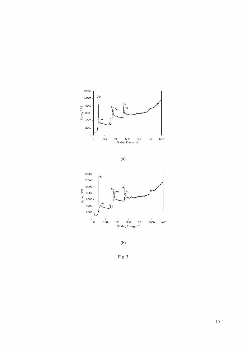
Figure 3. X-ray photoelectron spectra of mesoporous gold surfaces; (a) 100mesoAu and (b) 5050mesoAu.

Figure 4. Electrochemical stability in time of 100mesoAu, 5050mesoAu and sAu electrodes. The capacitance

values were obtained from cyclic voltammetry experiments in 5 mM phosphate buffer pH 7.5 containing 0.1

M KCl, where the potential was scanned from 200 mV to 0 mV at 200 mV/sec scan rate. Capacitance was

sampled at 100 mV during the discharging process of the twentieth cycle.

Figure 5. Cyclic voltammograms for (a) 100mesoAu, (b) 5050mesoAu and (c) sAu electrodes in 5 mM

phosphate buffer pH 7.5 containing 0.1 M KCl.

Figure 6. Variation in capacitance of the electrodes as a function of scan rate. Values recorded in 5 mM

phosphate buffer pH 7.5 containing 0.1 M KCl.

Figure 7. Discharge of the normal and mesoporous gold electrodes (a) linear in time and (b) plotted against

the natural logarithm of time. Values recorded in 5 mM phosphate buffer pH 7.5 containing 0.1 M KCl.

Figure 8. Model for evaluation of potential discharge vs time: (a) RC circuit where R is the dynamic

resistance of the foulant layer and CTOT is the capacitance measured between the electrode and the electrolyte

solution, (b) the contribution of the capacitance due to the foulant Cf and the double layer of charges Cdl,

which are schematically drawn in (c).

Figure 9. Fouling of gold surfaces when immersed in pasteurized milk, at room temperature; (a) raw data and

(b) normalized comparison of the data sets, where C0 was the capacitance at time = 0 seconds.

12

Table 1. Capacitance values and related error, together with number of data points and correlation coefficient, in

the linear range from where the capacitance values were obtained (60-45 mV), for the gold electrodes in a

square-wave potential step experiments in 5 mM phosphate buffer pH 7.5, containing 0.1 M KCl.

Capacitance

(F/cm2)

Error (F/cm2)

Number of data

points

Correlation

coefficient

sAu 5.26·10-5

1.94·10-6

65 0.98

5050mesoAu 5.80·10-4

6.47·10-6

650 0.99

100mesoAu 8.86·10-4

9.18·10-6

1000 0.99

13

Fig. 1

14

(a)

(b)

Fig. 2

15

(a)

(b)

Fig. 3

16

Fig. 4

17

(a)

(b)

(c)

Fig. 5

18

Fig 6.

19

(a)

(b)

Fig. 7

20

Fig. 8

21

(a)

(b)

Fig. 9


Recommended