56
Message Master 4000 Remote Monitoring Controller User Manual Version 2.02 Model: RMC Important! Please read this user manual carefully before using this device.

Message Master 4000
Remote Monitoring Controller User Manual Version 2.02
Model: RMC
Important! Please read this user manual carefully before using this device.

Table of Contents CHAPTER 1: INTRODUCTION...............................................................................................................................2 CHAPTER 2: SAFE USE OF DEVICE...................................................................................................................3 CHAPTER 3: PRODUCT OVERVIEW...................................................................................................................6 CHAPTER 4: HARDWARE INSTALLATION..............................................................................................................11
INTERFACING TO EQUIPMENTS ......................................................................................................................................12 WIRING INSTRUCTIONS: EXAMPLE 1 .............................................................................................................................13 WIRING INSTRUCTIONS: EXAMPLE 2 .............................................................................................................................14
CHAPTER 5: SOFTWARE CONFIGURATION ..........................................................................................................15 STANDALONE CONFIGURATION .....................................................................................................................................17 NETWORK ENVIRONMENT CONFIGURATION .................................................................................................................17
CHAPTER 6: LOGIN PAGE ...........................................................................................................................................18 CHAPTER 7: STATUS PAGE........................................................................................................................................19 CHAPTER 8: IO CONFIG PAGE – INPUT ..................................................................................................................21
INPUT CONFIG: EXAMPLE 1 ...........................................................................................................................................22 INPUT CONFIG: EXAMPLE 2 ...........................................................................................................................................22
CHAPTER 9: IO CONFIG PAGE – OUTPUT..............................................................................................................24 CHAPTER 10: PHONE GROUP PAGE .......................................................................................................................25
OPERATION GROUP ........................................................................................................................................................25 ESCALATION GROUP ......................................................................................................................................................26 AUTHORIZED GROUP ......................................................................................................................................................26 FORWARD NUMBER ........................................................................................................................................................27 SMS SETTINGS...............................................................................................................................................................28
CHAPTER 11: ALARM GROUP PAGE .......................................................................................................................31 CHAPTER 12: ANALOG CONFIG PAGE ...................................................................................................................34 CHAPTER 13: EMAIL ALERT PAGE ..........................................................................................................................38 CHAPTER 14: ADMINISTRATION PAGE ..................................................................................................................40
CHANGE DEVICE ID ........................................................................................................................................................41 CHANGE DATE & TIME ...................................................................................................................................................41 NTP SERVER ...................................................................................................................................................................41 CHANGE ADMINISTRATOR PASSWORD .........................................................................................................................41 CHANGE GUEST PASSWORD .........................................................................................................................................42 NETWORK CONFIGURATION ...........................................................................................................................................42
CHAPTER 15: EVENT LOG PAGE ..............................................................................................................................44 CHAPTER 16: HELP PAGE ...........................................................................................................................................46
QUERY MOBILE PHONE NUMBERS ................................................................................................................................47 PHONE MANAGEMENT ....................................................................................................................................................47 QUERY IO & SYSTEM STATUS ........................................................................................................................................48 OUTPUT CONTROL..........................................................................................................................................................48 REPEAT CONFIGURATION...............................................................................................................................................49
CHAPTER 17: ABOUT PAGE .......................................................................................................................................50 CHAPTER 18: LOGOFF PAGE.....................................................................................................................................50 APPENDIX A .....................................................................................................................................................................51
SETTING A STATIC IP ADDRESS FOR WINDOWS 98.....................................................................................................51 SETTING A STATIC IP ADDRESS FOR WINDOWS 2000 / WINDOWS XP......................................................................54
Linkwise Technology Pte Ltd Message Master 4000 User Manual
2
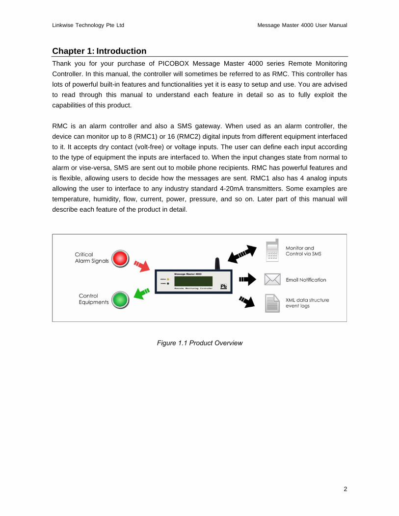
Chapter 1: Introduction Thank you for your purchase of PICOBOX Message Master 4000 series Remote Monitoring Controller. In this manual, the controller will sometimes be referred to as RMC. This controller has lots of powerful built-in features and functionalities yet it is easy to setup and use. You are advised to read through this manual to understand each feature in detail so as to fully exploit the capabilities of this product. RMC is an alarm controller and also a SMS gateway. When used as an alarm controller, the device can monitor up to 8 (RMC1) or 16 (RMC2) digital inputs from different equipment interfaced to it. It accepts dry contact (volt-free) or voltage inputs. The user can define each input according to the type of equipment the inputs are interfaced to. When the input changes state from normal to alarm or vise-versa, SMS are sent out to mobile phone recipients. RMC has powerful features and is flexible, allowing users to decide how the messages are sent. RMC1 also has 4 analog inputs allowing the user to interface to any industry standard 4-20mA transmitters. Some examples are temperature, humidity, flow, current, power, pressure, and so on. Later part of this manual will describe each feature of the product in detail.
Figure 1.1 Product Overview

Linkwise Technology Pte Ltd Message Master 4000 User Manual
3
Chapter 2: Safe Use of Device The following section contains important operating and maintenance (servicing) instructions. Please read it carefully. Warnings To reduce the risk of electric shock:
• Do not remove the cover (or back) of this device. There are no user-serviceable parts inside. Refer servicing to qualified service personnel.
• Do not expose this device to rain or moisture
To reduce the risk of electric shock and electromagnetic interference, use only recommended accessories. Note The serial number of this device is shown on the side of the product. You should record the number and other vital information here and retain this booklet as a permanent record of your purchase. Model No.: Serial No.: Date of Purchase: Dealer Purchased from: Dealer Address: Dealer Telephone No.: Important Safety Instructions In these safety instructions, the word [device] refers to the Message Master 4000 (RMC) and all its accessories. Read Instructions – Read all the safety and operating instructions before operating the device.
• Retain Instructions – Save the safety and operating instructions for future reference.
• Heed Warnings – Heed all warnings on the device and in the operating instructions.
• Follow Instructions – Follow all operating and maintenance instructions.
• Cleaning – Unplug this device from the wall outlet before cleaning. Wipe the device with a clean soft cloth. If necessary, put a cloth in diluted neutral detergent and wring it well before wiping the device with it. Finally, clean the device with a clean dry cloth. Do not use benzene, thinner or other volatile liquids or pesticides as they may damage the
!

Linkwise Technology Pte Ltd Message Master 4000 User Manual
4
product’s finishing. When using chemically treated cleaning cloths, observe their precautions accordingly.
• Accessories – Use only accessories recommended in this manual. Always use specified
connection cables. Be careful to connect devices correctly.
• Water and Moisture (Hazard of electric shock) – Do not use the device near water or in rainy or moist situations.
• Ambient Temperature – Do not put this device near a heater.
• Placing or Moving – Do not place this device on an unstable cart, stand, tripod, bracket or
table. The device may fall and cause serious damage to itself and serious injury to others. A device and cart combination should be moved with care. Quick stops, excessive force and uneven surfaces may cause the device and cart combination to overturn.
• Power Sources – The AC adapter should be operated only from the type of power source
indicated on the marking label. If you are not sure of the type of power supply to your premises, consult your device dealer or local power company.
• Power Cord Protection – Power cords should be routed so that they are not likely to be
walked on, or pinched by items placed upon or against them. Pay particular attention to plugs and the point from which the cords exit the device.
• Outdoor Antenna Grounding – If an outside antenna is connected to the device, be sure
the antenna is grounded so as to provide some protection against voltage surges and built-up static charges.
• Lightning – For added protection of this device during a lightning storm, or when it is left
unattended and unused for long periods of time, disconnect it from the wall outlet and disconnect the antenna. This will prevent damage to the device due to lightning and power-line surges.
• Power Lines – An outside antenna system should not be located in the vicinity of overhead
power lines or other electric light or power circuits, or where it can fall into such power lines or circuits. When installing an outside antenna system, extreme care should be taken to keep from touching such power lines or circuits, as contact with them might be fatal.
• Overloading – Do not overload wall outlets and extension cords as this can result in a risk
of fire or electric shock.
• Object and Liquid Entry – Never push objects of any kind into this device through openings as they may touch dangerous voltage points or short out parts that could result in a fire or electric shock. Be careful not to spill liquid of any kind onto the device.
• Servicing – Do not attempt to service this device yourself as opening or removing covers
may expose you to dangerous voltage or other hazards. Refer all servicing to qualified personnel. Opening the cover may void your warranty.
• Do not install the device in the following locations as this can cause a fire or electric shock:
Hot locations Close to a fire Very humid or dusty locations Locations exposed to direct sunlight Locations exposed to salt spray

Linkwise Technology Pte Ltd Message Master 4000 User Manual
5
Close to flammable solvents (alcohol, thinners, etc.)
• If any of the following occurs, immediately switch the device OFF, unplug it from the mains power supply and contact your distributor or agent:
The device emits any smoke, heat, abnormal noise, or unusual odour A metal object falls into the device The device is damaged in some way
Do not continue to use the device as this can cause a fire or electric shock.
• Please observe the following when using the device. Failure to do so can result in a fire or electric shock.
Do not use flammable sprays near the device. Do not subject the device to strong impact.
Linkwise Technology Pte Ltd Message Master 4000 User Manual
6
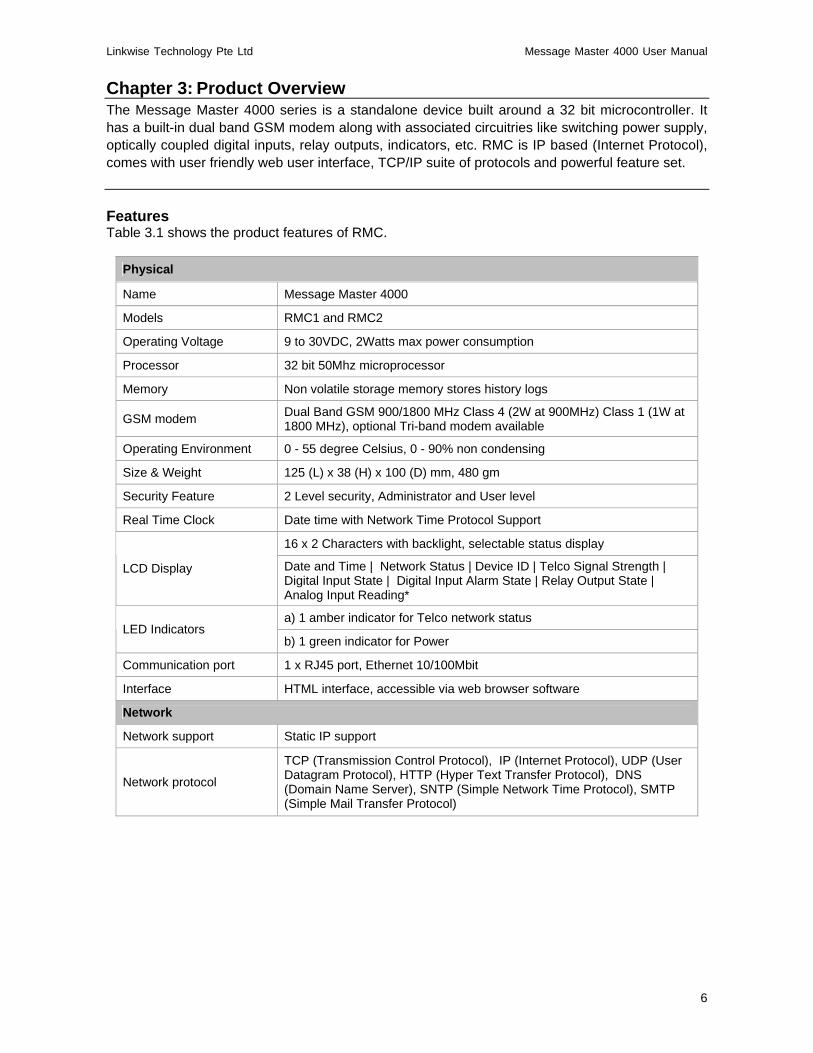
Chapter 3: Product Overview The Message Master 4000 series is a standalone device built around a 32 bit microcontroller. It has a built-in dual band GSM modem along with associated circuitries like switching power supply, optically coupled digital inputs, relay outputs, indicators, etc. RMC is IP based (Internet Protocol), comes with user friendly web user interface, TCP/IP suite of protocols and powerful feature set. Features Table 3.1 shows the product features of RMC.
Physical
Name Message Master 4000
Models RMC1 and RMC2
Operating Voltage 9 to 30VDC, 2Watts max power consumption
Processor 32 bit 50Mhz microprocessor
Memory Non volatile storage memory stores history logs
GSM modem Dual Band GSM 900/1800 MHz Class 4 (2W at 900MHz) Class 1 (1W at 1800 MHz), optional Tri-band modem available
Operating Environment 0 - 55 degree Celsius, 0 - 90% non condensing
Size & Weight 125 (L) x 38 (H) x 100 (D) mm, 480 gm
Security Feature 2 Level security, Administrator and User level
Real Time Clock Date time with Network Time Protocol Support
16 x 2 Characters with backlight, selectable status display
LCD Display Date and Time | Network Status | Device ID | Telco Signal Strength | Digital Input State | Digital Input Alarm State | Relay Output State | Analog Input Reading*
a) 1 amber indicator for Telco network status LED Indicators
b) 1 green indicator for Power
Communication port 1 x RJ45 port, Ethernet 10/100Mbit
Interface HTML interface, accessible via web browser software
Network
Network support Static IP support
Network protocol
TCP (Transmission Control Protocol), IP (Internet Protocol), UDP (User Datagram Protocol), HTTP (Hyper Text Transfer Protocol), DNS (Domain Name Server), SNTP (Simple Network Time Protocol), SMTP (Simple Mail Transfer Protocol)

Linkwise Technology Pte Ltd Message Master 4000 User Manual
7
Digital Input
No of Input points 8 (RMC1) or 16 (RMC2) optically coupled dry contact or voltage inputs
Configuration Independent configuration of input description, open/close status description
Input Response Time Individual selection of response time for each input from 0.2 to 30 seconds (trigger sensitivity)
Alarm State Definable normally open or close as Alarm condition
Relay Output
No of Output points 4 (RMC1) or 2 (RMC2) relay outputs, contacts rated at 30VDC 2A
Configuration User defined output description
Output control Through SMS or Local On / Off relay outputs through web browser
Auxiliary Contact Output Option to activate 4th Output state automatically on Alarm state
Auxiliary Output duration Option time interval from 1sec to infinity on Alarm state
Internal Buzzer Option time interval from 10 to 60 secs on Alarm state
Analog Input *
No of Analog points 4 analog input, 4-20mA, 10-bit resolutions
Configuration Configurable input description, scaling, trigger delay, high/low alarm points
Analog Input Response Time
Individual selection of alarm delay triggering for each analog input from 2 to 30 secs (trigger sensitivity)
Email Alert
5 email recipients Email Group
Server Authentication support
Time Stamp Email sent with time stamps with configurable subject
Event Log
Event Logging Stores up to 500 History logs with Date / Time stamp, FIFO event recording
Data Format XML (Extensible Markup Language), allows users to define their own tags in Excel or Web interface
Security Enable or disable XML data access from external application
Remote Management
a) Query health status
b) Query input / output / analog* status
c) On / Off/ Pulse output equipments / devices
d) Add / Edit / Delete mobile phone numbers
e) Query Operational/ Authorizer/ Escalation/ Forwarder mobile phone numbers
Remote Command via SMS
f) Acknowledgements
Linkwise Technology Pte Ltd Message Master 4000 User Manual
8
SMS Alert
a) 40 mobile phone numbers for Operational
b) 5 mobile phone numbers for 1st level Escalation
c) 5 mobile phone numbers for 2nd level Escalation
d) 1 mobile phone number for Forwarder
Phone Groups
e) accepts International Phone Number format
Configurable SMS Message
Digital inputs, relay outputs & analog input (2 messages per input, One for On State and Off State Triggering)
Auto Health Check Programmable daily/weekly system health check
Time Stamp SMS sent & received with time stamps up to the seconds
Table 3.1 Product Features
* Not available in RMC2 Package contents
1. Remote Monitoring Controller 2. 12V DC adapter 3. 10 way terminal block x 2 4. 6 way terminal block 5. GSM antenna, SMA mount 6. Ethernet Cross Cable 7. CD containing product brochure and user manual 8. Warranty card
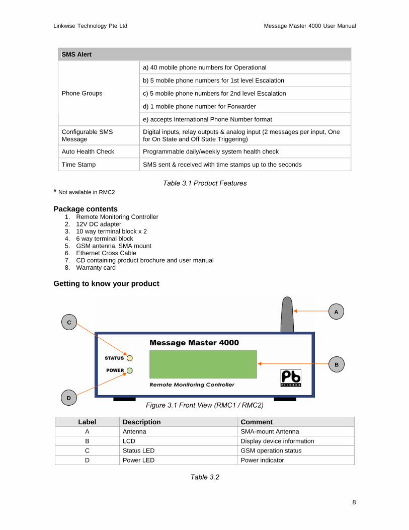
Getting to know your product
Figure 3.1 Front View (RMC1 / RMC2)
Label Description Comment
A Antenna SMA-mount Antenna B LCD Display device information C Status LED GSM operation status D Power LED Power indicator
Table 3.2
C
A
B
D

Linkwise Technology Pte Ltd Message Master 4000 User Manual
9
Figure 3.2 Back View ( RMC1)
Figure 3.3 Back View ( RMC2)
Label Description Comment A Reset Button Reset device to Factory Default B 10 way pluggable screw terminal Power and IO connectors C 10 way pluggable screw terminal IO connectors D 6 ways pluggable screw terminal IO connectors E Sim Card Tray Holder for Sim card F SMA connector SMA-mount antenna G Ethernet port Standard RJ-45 connector
Table 3.3
F
B
C
G
E
D
A
Linkwise Technology Pte Ltd Message Master 4000 User Manual
10
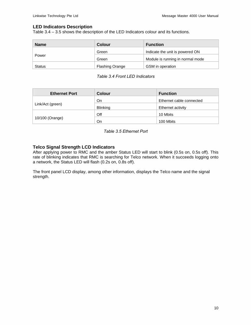
LED Indicators Description Table 3.4 – 3.5 shows the description of the LED Indicators colour and its functions. Name Colour Function
Green Indicate the unit is powered ON Power
Green Module is running in normal mode
Status Flashing Orange GSM in operation
Table 3.4 Front LED Indicators
Ethernet Port Colour Function On Ethernet cable connected
Link/Act (green) Blinking Ethernet activity
Off 10 Mbits 10/100 (Orange)
On 100 Mbits
Table 3.5 Ethernet Port
Telco Signal Strength LCD Indicators After applying power to RMC and the amber Status LED will start to blink (0.5s on, 0.5s off). This rate of blinking indicates that RMC is searching for Telco network. When it succeeds logging onto a network, the Status LED will flash (0.2s on, 0.8s off).
The front panel LCD display, among other information, displays the Telco name and the signal strength.

Linkwise Technology Pte Ltd Message Master 4000 User Manual
11
Chapter 4: Hardware Installation This section will guide you through the installation of your RMC. Just follow the instructions here and you will have your RMC installed very quickly. Before starting installation, ensure that the unit is powered OFF and the power adapter plug disconnected from the POWER connectors of the unit Step 1. Determine a suitable location for the RMC In selecting a location, remember that you will
need to connect the power adapter, termination blocks and Ethernet cable, and have GSM signals. Follow carefully the instructions provided earlier in this manual on the safe use of this device.
Step 2. Insert a valid GSM mobile telephone SIM card into the SIM card socket slot on the front
panel of the RMC. • To insert the card, first eject the SIM card tray by pushing the yellow eject button. Do this
using a small blunt tool. Example: paper clip or a Philips head screwdriver. (Figure 4.1) • Place the SIM card on the tray and insert the tray into the holder. Ensure correct
orientation. The SIM should be facing upwards
• Position it horizontally and slide it in with a gentle force. If you experience tightness or friction when attempting to insert the tray, do not force it in. Check that the SIM card is sitting firmly on the tray.
• Slide it in all the way until you feel it touching the end. About 1 mm of the SIM card tray
will remain exposed to allow its removal.
Step 3. Attach the antenna provided in the package onto the antenna socket. If an external antenna is required, contact your distributor for more information on external high gain antenna.
Step 4. Wire the input/output connection between the equipment and RMC using the supplied pluggable screw terminal connectors provided.
Figure 4.1 Eject Sim Card Tray
1) Push this yellow button to eject Sim Card Tray with a blunt tool.
Connect the Ethernet cable to the Ethernet port
2) Insert tray with Sim Card facing upwards
Linkwise Technology Pte Ltd Message Master 4000 User Manual
12
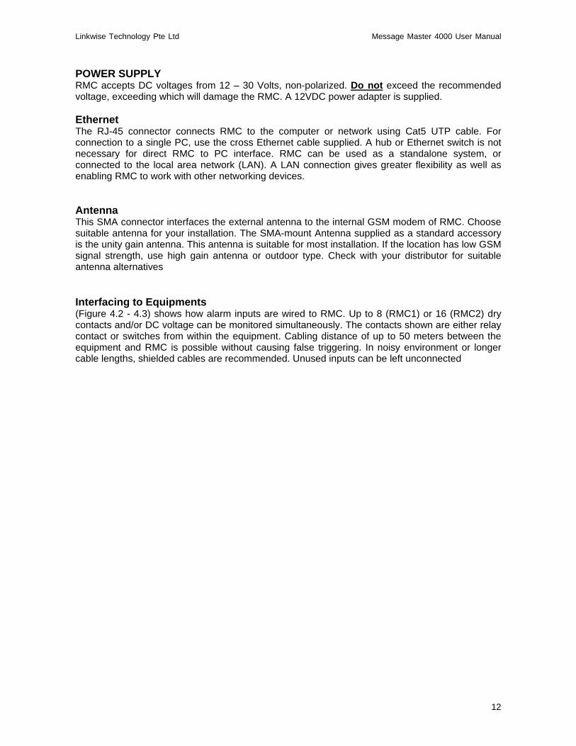
POWER SUPPLY RMC accepts DC voltages from 12 – 30 Volts, non-polarized. Do not exceed the recommended voltage, exceeding which will damage the RMC. A 12VDC power adapter is supplied. Ethernet The RJ-45 connector connects RMC to the computer or network using Cat5 UTP cable. For connection to a single PC, use the cross Ethernet cable supplied. A hub or Ethernet switch is not necessary for direct RMC to PC interface. RMC can be used as a standalone system, or connected to the local area network (LAN). A LAN connection gives greater flexibility as well as enabling RMC to work with other networking devices. Antenna This SMA connector interfaces the external antenna to the internal GSM modem of RMC. Choose suitable antenna for your installation. The SMA-mount Antenna supplied as a standard accessory is the unity gain antenna. This antenna is suitable for most installation. If the location has low GSM signal strength, use high gain antenna or outdoor type. Check with your distributor for suitable antenna alternatives
Interfacing to Equipments (Figure 4.2 - 4.3) shows how alarm inputs are wired to RMC. Up to 8 (RMC1) or 16 (RMC2) dry contacts and/or DC voltage can be monitored simultaneously. The contacts shown are either relay contact or switches from within the equipment. Cabling distance of up to 50 meters between the equipment and RMC is possible without causing false triggering. In noisy environment or longer cable lengths, shielded cables are recommended. Unused inputs can be left unconnected

Linkwise Technology Pte Ltd Message Master 4000 User Manual
13
Wiring Instructions: Example 1 (Figure 4.2) shows the power supply connection to RMC1. Power to RMC can be from 12-24 Volts. A 12VDC adapter is supplied as a standard accessory. The digital inputs shown are dry contacts type. The 4 outputs are relay types with contact ratings of 30V, 2 amps DC max. Also shown in this figure are four 4-20mA transmitters, 2-wire loop powered. Depending on the power requirement of the transmitter, a higher voltage may be needed. In this case, change the power supply to a higher voltage type, but not higher than 30 volts.
Figure 4.2 Wiring Diagram Example 1

Linkwise Technology Pte Ltd Message Master 4000 User Manual
14
Wiring Instructions: Example 2 (Figure 4.3) shows the wiring of RMC1 having a separate power supply for the analog inputs. In cases where the 4-20mA transmitters require an operating voltage of higher than 24 volts, this configuration is recommended. This figure also shows how to interface voltage source digital inputs. The example here shows that input X1, X2, X7, X8 are voltage source inputs. X3, X4, X5, X6 are dry contact inputs. Users can use dry contact or voltage source for any or all the inputs.
Figure 4.3 Wiring Diagram Example 2
Linkwise Technology Pte Ltd Message Master 4000 User Manual
15
Chapter 5: Software Configuration Configuration of messages, phone groups etc are done via the Ethernet port. Alarm Triggering An alarm event happens when any one or more digital input changes state. RMC continuously monitor the input for these events. When an alarm event occurs, it picks up information from the configuration memory and performs the necessary SMS actions. Depending on the configuration, some or all the mobile phones specified will receive the SMS message. The format of the message is [Date/Time] [Device ID] [Input description] → [Status] Date/Time The time of alarm event occurs. The real-time clock within RMC provides the time stamping information. Device ID The identity assigned by the user during software configuration. Input Description The user defines input description and status during software configuration. Each digital input will have its own unique input description name and status text. Example of an SMS alarm message:
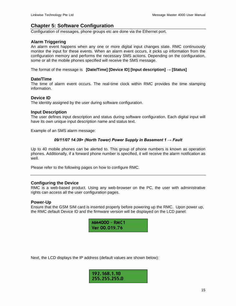
09/11/07 14:39> (North Tower) Power Supply in Basement 1 → Fault Up to 40 mobile phones can be alerted to. This group of phone numbers is known as operation phones. Additionally, if a forward phone number is specified, it will receive the alarm notification as well. Please refer to the following pages on how to configure RMC. Configuring the Device RMC is a web-based product. Using any web-browser on the PC, the user with administrative rights can access all the user configuration pages. Power-Up Ensure that the GSM SIM card is inserted properly before powering up the RMC. Upon power up, the RMC default Device ID and the firmware version will be displayed on the LCD panel:
Next, the LCD displays the IP address (default values are shown below):

Linkwise Technology Pte Ltd Message Master 4000 User Manual
16
Next, the LCD displays the default Device ID:
The date and time are then displayed. The date is formatted as dd-mm-yyyy:
Upon successful detection of the SIM card and GSM network, the display shows the network service provider and the signal strength:
Next, the LCD displays the Digital Input State (depending on the DI state) If connected equipment is in Open state, a ‘0’ will display on the respective column. If connected equipment is in Close state, a ‘c’ will display on the respective column.
Next, the LCD displays the Digital Input Alarm State (Normal state is blank) If connected equipment is in alarm state, a ‘X’ display will appear on the respective column.
Next, the LCD displays the Relay Output State If connected equipment is in Open state, a ‘0’ will display on the respective column. If connected equipment is in Close state, a ‘1’ will display on the respective column.

Linkwise Technology Pte Ltd Message Master 4000 User Manual
17
Next, the LCD displays the first 2 Analog Input readings (default is disabled)
Next, the LCD displays next 2 Analog Input readings (default is disabled)
Standalone Configuration In a standalone environment with one RMC directly connected to a standalone PC, requires a crossover Ethernet cable, which is supplied with the RMC unit. In order for the PC and the RMC to ‘see’ each other, the PC must be manually set to a static IP address that is within the same subnet as the RMC. Given the default configuration of IP address 192.168.1.10 and 255.255.255.0 for the subnet mask, a suitable IP addresses for the PC would be 192.168.1.100 or any other IP address other then 192.168.1.10. Warning Remember that you SHOULD NOT use the same IP address 192.168.1.10 for your PC and RMC and both PC and RMC need to be within the same subnet. If you are unsure of how to set static IP address for your PC, please consult your PC operating system’s documentation for details or Appendix A. Network Environment Configuration If the RMC is connected to a network with multiple PCs, be careful of the effects of any DHCP servers. RMC does not contain DCHP capabilities, and remember that for the PC and the RMC to ‘see’ each other, the IP addresses of the PC and RMC must be in the same subnet. For a network with a DHCP server, you must allocate a fixed IP address for use by the RMC unit, and your RMC’s IP address must be set to this address. If the RMC default settings are not suitable, connect RMC to a standalone PC to first change the settings to the IP address that you have allocated to it, and the required subnet mask (see the following sections on changing the default RMC IP settings) before connecting your RMC to your network. Consult your network system administrator if you have doubts. When swapping a RMC connection between a network and a standalone PC, remember that a direct connection to a standalone PC requires a crossover Ethernet cable, which is supplied with the RMC unit. Accessing RMC Web Pages Once the IP address of RMC is known, the user can setup the device using the PC browser. The PC IP address must be in the same network range as the device. To learn more about IP address and subnet mask, visit www.learntosubnet.com Open the browser application on your PC. It can be Internet Explorer (version 6 and above), Firefox, Netscape, Opera or any other standard web browser. Open your web browser, at the address bar, type in the IP address of RMC and press Enter, the Login Page is then loaded.

Linkwise Technology Pte Ltd Message Master 4000 User Manual
18
Chapter 6: Login Page The login page will appear. Enter the User Name and Password on the text box. The default user name for administrator is admin. Password: admin. Guest user login user name is guest. Password: guest. Administrator user can change the password in the Administration page.
Figure 6.1: Login Page Follow through the various pages to setup the parameters according to the user requirement.

Linkwise Technology Pte Ltd Message Master 4000 User Manual
19
Chapter 7: Status Page Once the user successfully logs in, the status page appears. In a new un-configured unit, the status page shows all preset information about the input and output states.
Figure 7.1 Status Page The left hand side of the page has a set of menu or navigation buttons. On the right side is the page of the currently selected choice. Click on any of the buttons will bring the respective pages out.
Figure 7.2 Menu or Navigation Buttons
Linkwise Technology Pte Ltd Message Master 4000 User Manual
20
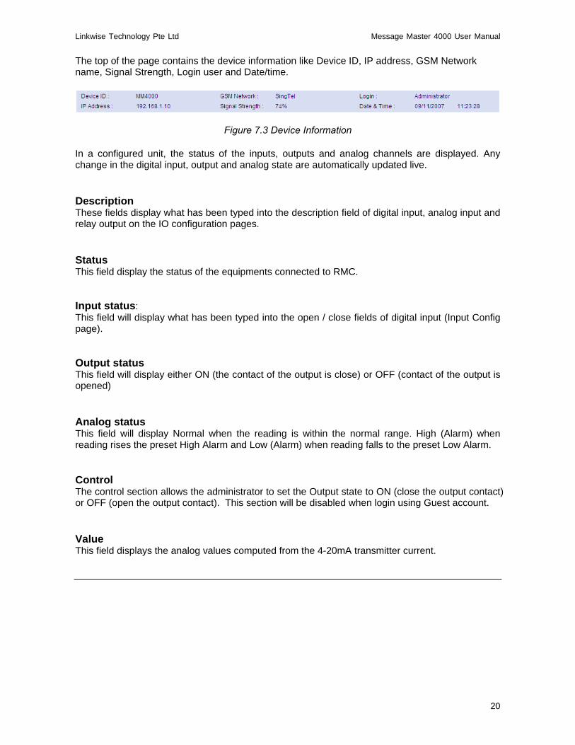
The top of the page contains the device information like Device ID, IP address, GSM Network name, Signal Strength, Login user and Date/time.
Figure 7.3 Device Information
In a configured unit, the status of the inputs, outputs and analog channels are displayed. Any change in the digital input, output and analog state are automatically updated live. Description These fields display what has been typed into the description field of digital input, analog input and relay output on the IO configuration pages. Status This field display the status of the equipments connected to RMC. Input status: This field will display what has been typed into the open / close fields of digital input (Input Config page). Output status This field will display either ON (the contact of the output is close) or OFF (contact of the output is opened) Analog status This field will display Normal when the reading is within the normal range. High (Alarm) when reading rises the preset High Alarm and Low (Alarm) when reading falls to the preset Low Alarm. Control The control section allows the administrator to set the Output state to ON (close the output contact) or OFF (open the output contact). This section will be disabled when login using Guest account. Value This field displays the analog values computed from the 4-20mA transmitter current.
Linkwise Technology Pte Ltd Message Master 4000 User Manual
21
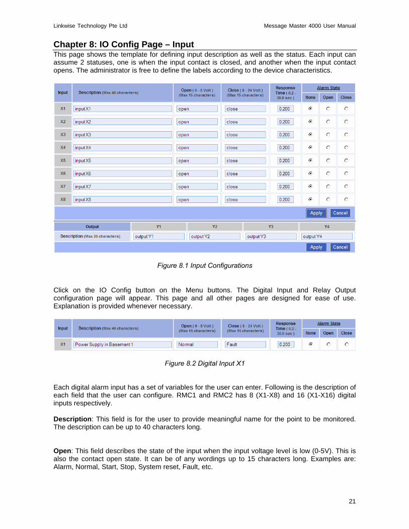
Chapter 8: IO Config Page – Input This page shows the template for defining input description as well as the status. Each input can assume 2 statuses, one is when the input contact is closed, and another when the input contact opens. The administrator is free to define the labels according to the device characteristics.
Figure 8.1 Input Configurations Click on the IO Config button on the Menu buttons. The Digital Input and Relay Output configuration page will appear. This page and all other pages are designed for ease of use. Explanation is provided whenever necessary.
Figure 8.2 Digital Input X1
Each digital alarm input has a set of variables for the user can enter. Following is the description of each field that the user can configure. RMC1 and RMC2 has 8 (X1-X8) and 16 (X1-X16) digital inputs respectively. Description: This field is for the user to provide meaningful name for the point to be monitored. The description can be up to 40 characters long.
Open: This field describes the state of the input when the input voltage level is low (0-5V). This is also the contact open state. It can be of any wordings up to 15 characters long. Examples are: Alarm, Normal, Start, Stop, System reset, Fault, etc.

Linkwise Technology Pte Ltd Message Master 4000 User Manual
22
Close: This field describes the state of the input when the input voltage level is low (8-24V). This is also the contact close state. It can be of any wordings up to 15 characters long. Examples are: Alarm, Normal, Start, Stop, System reset, Fault etc. Response Time: This defines the minimum time the input level must remain in order for the device to register a change in state. The default setting is 0.2 sec or 200 millisecond. This value can be set from between 0.2 sec to 30 sec. Alarm state: Three possible settings can be selected – None, Open, Close. This setting defines what the alarm state is. The status page will show the state of the input, based on the state description configured. Input Config: Example 1 Below is an example of defining the input state X1 as a non alarm input Input Config:- Alarm state None (Figure 8.3 - 8.5) shows Input X1 set to Alarm State None. If X1 is use as a status monitoring input, select the ‘None’ radio button. In this selection, no SMS is sent when the input changes states.
Figure 8.3 Digital Input X1 Alarm:-None Status:- Alarm state None
Figure 8.4 Status X1 Contact Open
Figure 8.5 Status X1 Contact Close
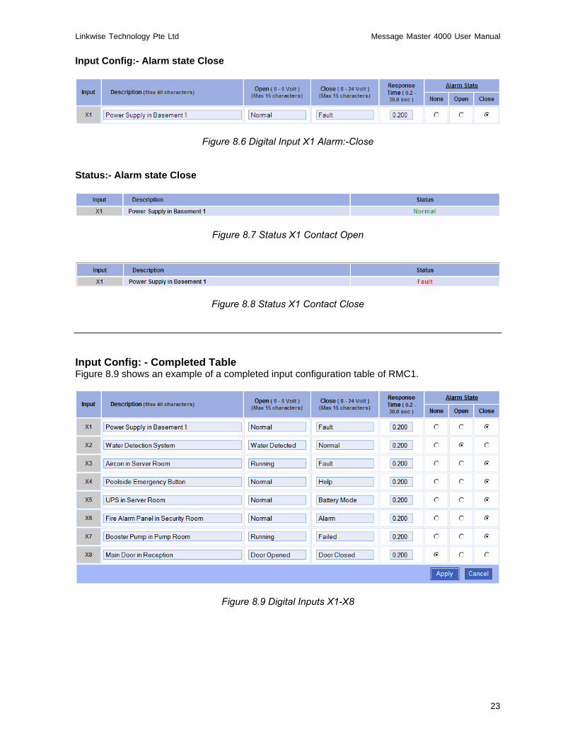
Input Config: Example 2 Below is an example of defining the input state X1 as a contact Close as alarm. Input Config:- Alarm state Close (Figure 8.6 - 8.8) shows Input X1 set to Alarm State Close. If X1 is set as contact close on alarm, select the ‘Close’ radio button. In this selection, Alarm SMS will be sent out when the input X1 changes from Open to Close state.
Linkwise Technology Pte Ltd Message Master 4000 User Manual
23
Input Config:- Alarm state Close
Figure 8.6 Digital Input X1 Alarm:-Close
Status:- Alarm state Close
Figure 8.7 Status X1 Contact Open
Figure 8.8 Status X1 Contact Close
Input Config: - Completed Table Figure 8.9 shows an example of a completed input configuration table of RMC1.
Figure 8.9 Digital Inputs X1-X8
Linkwise Technology Pte Ltd Message Master 4000 User Manual
24
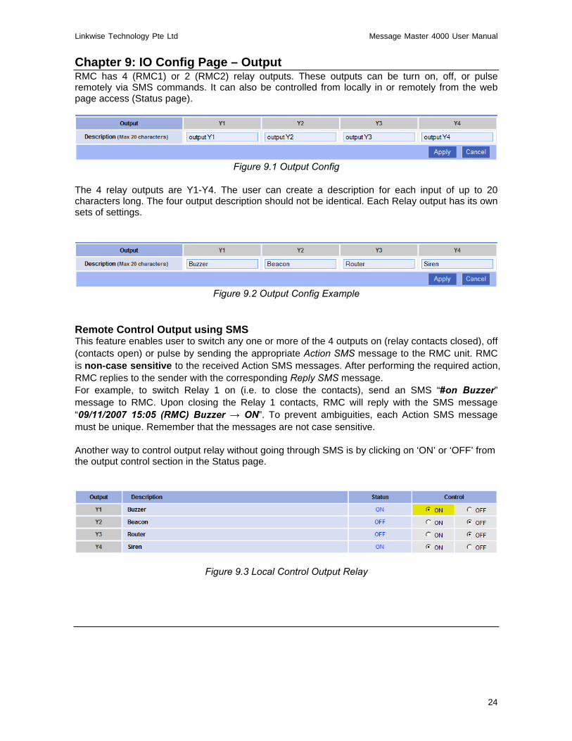
Chapter 9: IO Config Page – Output RMC has 4 (RMC1) or 2 (RMC2) relay outputs. These outputs can be turn on, off, or pulse remotely via SMS commands. It can also be controlled from locally in or remotely from the web page access (Status page).
Figure 9.1 Output Config
The 4 relay outputs are Y1-Y4. The user can create a description for each input of up to 20 characters long. The four output description should not be identical. Each Relay output has its own sets of settings.
Figure 9.2 Output Config Example
Remote Control Output using SMS This feature enables user to switch any one or more of the 4 outputs on (relay contacts closed), off (contacts open) or pulse by sending the appropriate Action SMS message to the RMC unit. RMC is non-case sensitive to the received Action SMS messages. After performing the required action, RMC replies to the sender with the corresponding Reply SMS message. For example, to switch Relay 1 on (i.e. to close the contacts), send an SMS “#on Buzzer” message to RMC. Upon closing the Relay 1 contacts, RMC will reply with the SMS message “09/11/2007 15:05 (RMC) Buzzer → ON”. To prevent ambiguities, each Action SMS message must be unique. Remember that the messages are not case sensitive. Another way to control output relay without going through SMS is by clicking on ‘ON’ or ‘OFF’ from the output control section in the Status page.
Figure 9.3 Local Control Output Relay

Linkwise Technology Pte Ltd Message Master 4000 User Manual
25
Chapter 10: Phone Group Page This page shows the recipients mobile phone numbers, organised into 8 (A-H) Operational groups, 5 user in Escalation Group A, 5 user in Escalation Group B, 3 user in Authorized group & 1 user in Forward group. In operational group there are 5 users in each group. Click Apply for any changes to take effect. International dialling codes can be used. Example: +65912345678.
Figure 10.1 Phone Group
Operation Group These groups of users are those that will receive alarm SMS when one or more digital inputs are activated (open → close, close → open). Analog Input are activated (normal → high, high → normal, normal → low, low → normal). Up to 40 mobile phone numbers can be assigned to this groups. Phone numbers of up to 14 numeric characters and (+) are valid formats. Example 912345678, +65912345678.
Linkwise Technology Pte Ltd Message Master 4000 User Manual
26
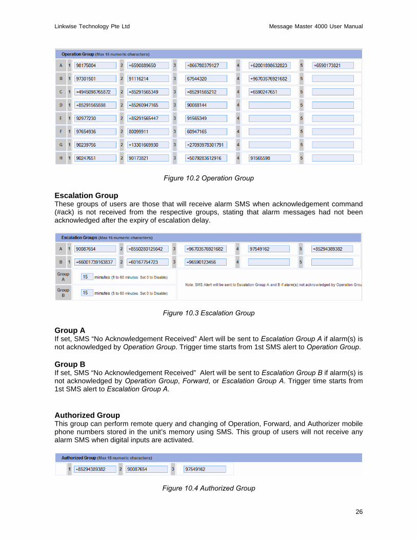
Figure 10.2 Operation Group Escalation Group These groups of users are those that will receive alarm SMS when acknowledgement command (#ack) is not received from the respective groups, stating that alarm messages had not been acknowledged after the expiry of escalation delay.
Figure 10.3 Escalation Group Group A If set, SMS “No Acknowledgement Received” Alert will be sent to Escalation Group A if alarm(s) is not acknowledged by Operation Group. Trigger time starts from 1st SMS alert to Operation Group. Group B If set, SMS “No Acknowledgement Received” Alert will be sent to Escalation Group B if alarm(s) is not acknowledged by Operation Group, Forward, or Escalation Group A. Trigger time starts from 1st SMS alert to Escalation Group A. Authorized Group This group can perform remote query and changing of Operation, Forward, and Authorizer mobile phone numbers stored in the unit’s memory using SMS. This group of users will not receive any alarm SMS when digital inputs are activated.
Figure 10.4 Authorized Group
Linkwise Technology Pte Ltd Message Master 4000 User Manual
27
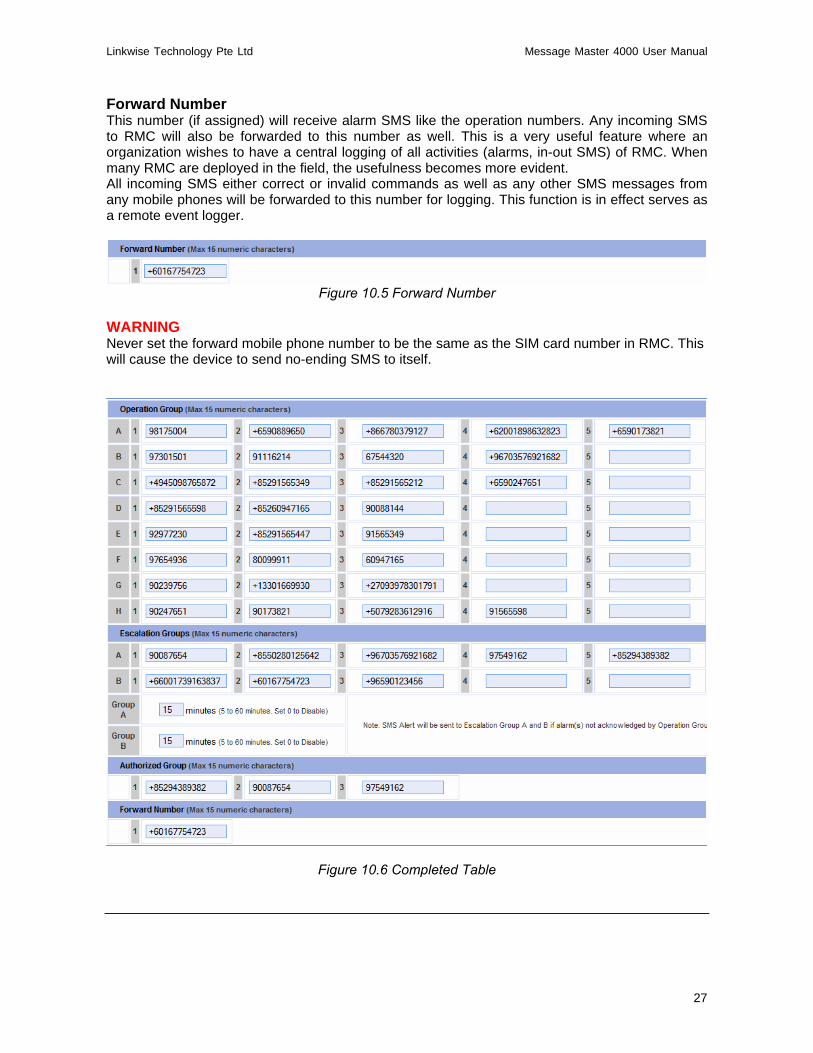
Forward Number This number (if assigned) will receive alarm SMS like the operation numbers. Any incoming SMS to RMC will also be forwarded to this number as well. This is a very useful feature where an organization wishes to have a central logging of all activities (alarms, in-out SMS) of RMC. When many RMC are deployed in the field, the usefulness becomes more evident. All incoming SMS either correct or invalid commands as well as any other SMS messages from any mobile phones will be forwarded to this number for logging. This function is in effect serves as a remote event logger.
Figure 10.5 Forward Number
WARNING Never set the forward mobile phone number to be the same as the SIM card number in RMC. This will cause the device to send no-ending SMS to itself.
Figure 10.6 Completed Table

Linkwise Technology Pte Ltd Message Master 4000 User Manual
28
SMS Settings This feature, when enabled will send the alarm SMS repeatedly up to 4 times to the operation and forward mobile phones. The repeat interval can be set between 2-30 minutes. Repeat SMS on Alarm State If set, when an alarm is triggered, the SMS will be sent repeatedly according to the number of times specified, to the operation and forward group. SMS Repeat Interval SMS repeat duration (2- 30mins).
Figure 10.7 SMS Settings
To cancel repeat sending, any mobile phone from the operation or forward must acknowledge to RMC by replying the acknowledge command (#ack). This command is non-case sensitive. #ack, #ACK, #Ack are valid strings. RMC upon receipt of the acknowledge command stop sending further SMS to this alarm. After the alarm or alarms is acknowledged, new alarms triggered will be sent and repeated until the next #ACK command is received by RMC. Set to None if no repeat is required. Send SMS when status returns to normal If Yes is selected, SMS will be sent once when status of Digital Input or Analog Input changes from Alarm to Normal state. There is no repeat for this ‘Normal’ SMS. If No is selected, SMS will not be sent out when status of Digital Input or Analog Input changes from Alarm to Normal state.

Linkwise Technology Pte Ltd Message Master 4000 User Manual
29
SMS Repeat and Escalation A and B Example: SMS Repeat: 4 Times (maximum) SMS Repeat Interval: 5 minutes Escalation Group A: 15 minutes Escalation Group B: 30 minutes Assuming no acknowledgment received by RMC from respective groups. Alarm Trigger Time: 10:00pm
Time Operation Forward Escalation A Escalation B 10:00pm Yes Yes 10:05pm Yes Yes 10:10pm Yes Yes 10:15pm Yes Yes Yes 10:20pm Yes Yes 10:25pm 10:30pm 10:35pm 10:40pm 10:45pm Yes
Table 10.4 SMS Repeat and Escalation A and B example
SIM Card Pin Code The user can opt to lock the SIM card to prevent unauthorized use of the SIM card. To enable to pin lock feature, place the SIM card on any mobile phone and use the phone function to lock the SIM card. (Refer to the phone manufacturer user manual for instruction). On the Sim Card Pin Code field, supply the same lock code as you have set using the mobile phone. Place the SIM card back to RMC. (Refer to the section on SIM card insertion for detail)
Figure 10.8 SMS Card Pin Lock Auto Health Check The “Auto Health Check” feature automatically report to recipients the health of RMC over SMS.: If “enable” is check, RMC will sent a SMS message on the preset Day and Time. If the auto health check is not enabled, users still can perform manual health check by sending ?syscheck to RMC via sms. If RMC is switched on, or working normally, it will reply to the querying mobile phone with
[Date / Time]> [Device ID] Auto Health Check: [Telco name] -> [Signal level] IP: [IP Address] System Check OK
Example 09/11/2007 14:39> (RMC) Auto Health Check: SingTel-G9 -> 90% IP:192.168.1.10 System Check OK
Forward mobile number, if specified will receive 2 messages from this action

Linkwise Technology Pte Ltd Message Master 4000 User Manual
30
1) ?syscheck from the querying mobile phone 2) Reply from RMC to the querying mobile phone Clear queued SMS If there is a situation of multiple alarms, the alarms are stored in memory queue for the GSM modem to perform SMS’ing of messages. If during the process of sending SMS, a power failure occurs, the queue information remains in memory. When power is restored, RMC will resume the sending of SMS. The Administrator can click on the Clear button to delete the queued SMS alarms. Send test SMS to Mobile Phone To test, type in the Mobile Phone number in the field and click Send to send out a test SMS.
Figure 10.9 Send test SMS

Linkwise Technology Pte Ltd Message Master 4000 User Manual
31
Chapter 11: Alarm Group Page This page is used for selecting the group of users to be notified when any of the 8 Digital Inputs switches close or open. Four Analog Inputs can monitor industrial standards 4-20mA transmitter parameters like, temperatures, humidity, pressures, etc. Each low or high alarm can notify up to 8 phone groups.
Figure 11.1 Alarm Group
Alarm Grouping – Digital Input The Enable checkbox enables the respective Digital Input alarms i.e. selects which alarms are active. In this way you can define alarm configurations beforehand and only enable the ones you require to be active at any particular time. Enable alarm conditions in group Check this box to select the whole group within the column.

Linkwise Technology Pte Ltd Message Master 4000 User Manual
32
Enable alarm conditions Check this box to select every checkboxes within the Digital Input table. The example below, Phone Group A has the whole column check boxes ticked, indicating Group A members are monitoring all the equipments X1 – X8. Whenever there is any alarm from any equipment, Group A will receive the SMS Alert. As for Phone Group B, its has the first four checkboxes ticked, indicating Group B members are monitoring equipment from X1-X4. As such, whenever there is any alarm from X1-X4 equipment, Group B will receive the SMS Alert, but will not receive any SMS Alert if there is any trigger from X5-X8 equipment.
Figure 11.2 Alarm Group - Digital Input
Alarm Grouping – Analog Input The Enable checkbox enables the respective Analog Input alarm, i.e. selects which alarms are active. In this way you can define alarm configurations beforehand and only enable the ones you require to be active at any particular time. Enable alarm conditions in group Check this box to select the whole group within the column. Enable alarm conditions Check this box to select every checkboxes within the Analog Input table. The example below shows for Probe 1 and 2, Groups A and B will be notified whenever the analog values crosses the low or high alarm limits. Groups A and C will monitor Probe 3 and 4 and be notified whenever the analog values crosses the low or high alarm limits.

Linkwise Technology Pte Ltd Message Master 4000 User Manual
33
Figure 11.3 Alarm Group - Analog Input (RMC1) Sound Internal Buzzer This feature will sound internal buzzer on alarm state. Whenever Digital Input changes from Normal to Alarm state or when Analog Input hits the alarm preset value. Select the buzzer duration from the dropdown box. Click Set for any changes to take effect.
Figure 11.4 Sounds Internal Buzzer
Trigger Output 4 (RMC1) / Output 2 (RMC2) This feature will trigger and close the contact of Relay Output Y4 (RMC1) or Relay Output Y2 (RMC2) on alarm state. Whenever Digital Input changes from Normal to Alarm state or when Analog Input hits the alarm preset value. Select the closing of the contact duration from the dropdown box or select ‘ON’ to leave the contact permanently closed till the alarm returns to normal state. Click Set for any changes to take effect. Figure 11.6 shows an example of connecting external alarm (Beacon) to Relay Output Y4.
Figure 11.5 Trigger Output Relay Y4
Figure 11.6 Trigger External Alarm (RMC1)
Beacon
External Power

Linkwise Technology Pte Ltd Message Master 4000 User Manual
34
Chapter 12: Analog Config Page This page shows four channels of 4-20mA analog input interfaces to any industrial standards transmitter. Any such transmitters can be used with RMC1 to monitor temperature, humidity, pressure, current, voltage, power, etc. Refer to the transmitter manufacture specification for help in inputting the fields in this page. RMC2 does not have analog input features.
Figure 12.1 Analog Input Config
Example of Analog Config:- Temperature
Figure 12.2 Example of Analog Input A1: Temperature
Linkwise Technology Pte Ltd Message Master 4000 User Manual
35
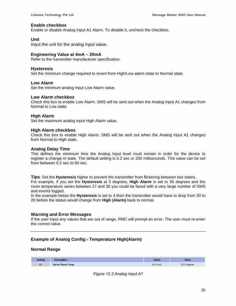
Enable checkbox Enable or disable Analog Input A1 Alarm. To disable it, uncheck the checkbox. Unit Input the unit for the analog input value. Engineering Value at 4mA – 20mA Refer to the transmitter manufacturer specification. Hysteresis Set the minimum change required to revert from High/Low alarm state to Normal state. Low Alarm Set the minimum analog input Low Alarm value. Low Alarm checkbox Check this box to enable Low Alarm. SMS will be sent out when the Analog input A1 changes from Normal to Low state. High Alarm Set the maximum analog input High Alarm value. High Alarm checkbox Check this box to enable High Alarm. SMS will be sent out when the Analog input A1 changes from Normal to High state. Analog Delay Time This defines the minimum time the Analog input level must remain in order for the device to register a change in state. The default setting is 0.2 sec or 200 milliseconds. This value can be set from between 0.2 sec to 60 sec. Tips: Set the Hysteresis higher to prevent the transmitter from flickering between two states. For example, if you set the Hysteresis at 3 degrees, High Alarm is set to 30 degrees and the room temperature varies between 27 and 30 you could be faced with a very large number of SMS and events logged. In the example below the Hysteresis is set to 4 then the transmitter would have to drop from 30 to 26 before the status would change from High (Alarm) back to normal. Warning and Error Messages If the user input any values that are out of range, RMC will prompt an error. The user must re-enter the correct value. Example of Analog Config:- Temperature High(Alarm) Normal Range
Figure 12.3 Analog Input A1

Linkwise Technology Pte Ltd Message Master 4000 User Manual
36
High Alarm (Figure 12.4- 12.5) shows Analog Input A1 in High Temperature Stage. When temperature rises to 30.0 degree, SMS will be send out stating Server Room Temp→ High (Alarm). When temperature falls to 26.0 degree, SMS will be sent out stating Server Room Temp→ Normal.
Figure 12.4 Status Analog Input A1 High Alarm
Figure 12.5 Status Analog Input A1 Normal State
Low Alarm (Figure 12.6- 12.7) shows Analog Input A1 in Low Temperature Stage. When temperature falls to 16.0 degree, SMS will be sent out stating Server Room Temp→ Low (Alarm). When temperature rises to 20.0 degree, SMS will be sent out stating Server Room Temp→ Normal.
Figure 12.6 Status Analog Input A1 Low Alarm
Figure 12.7 Status Analog Input A1 Normal State

Linkwise Technology Pte Ltd Message Master 4000 User Manual
37
Status: Completed Input / Output and Analog Input Example This page shows the example of a completed input/output configuration Status Page. Once the administrator configured successfully, the screen on the right side of the browser will display the updated table, showing the description the devices or equipment and the present status. The devices or equipment are those that are interfaced to RMC termination block. Relay outputs and Analog input are also shown on this same screen.
Figure 12.8 Status Page example
Sensor status colour indicator The colours Red and Green indicate at a glance the status, red is alarm state and green is in the normal state. Black indicates user had defined the equipment as non-critical.
Linkwise Technology Pte Ltd Message Master 4000 User Manual
38
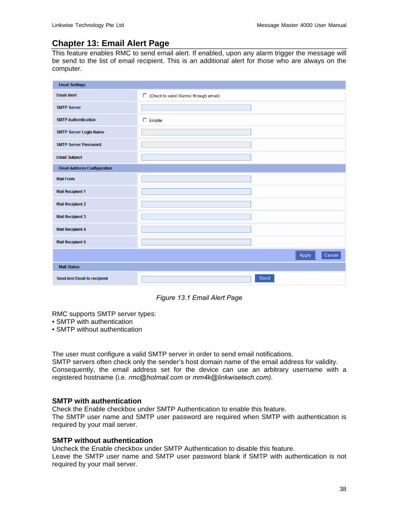
Chapter 13: Email Alert Page This feature enables RMC to send email alert. If enabled, upon any alarm trigger the message will be send to the list of email recipient. This is an additional alert for those who are always on the computer.
Figure 13.1 Email Alert Page RMC supports SMTP server types: • SMTP with authentication • SMTP without authentication The user must configure a valid SMTP server in order to send email notifications. SMTP servers often check only the sender’s host domain name of the email address for validity. Consequently, the email address set for the device can use an arbitrary username with a registered hostname (i.e. [email protected] or [email protected]). SMTP with authentication Check the Enable checkbox under SMTP Authentication to enable this feature. The SMTP user name and SMTP user password are required when SMTP with authentication is required by your mail server. SMTP without authentication Uncheck the Enable checkbox under SMTP Authentication to disable this feature. Leave the SMTP user name and SMTP user password blank if SMTP with authentication is not required by your mail server.
Linkwise Technology Pte Ltd Message Master 4000 User Manual
39
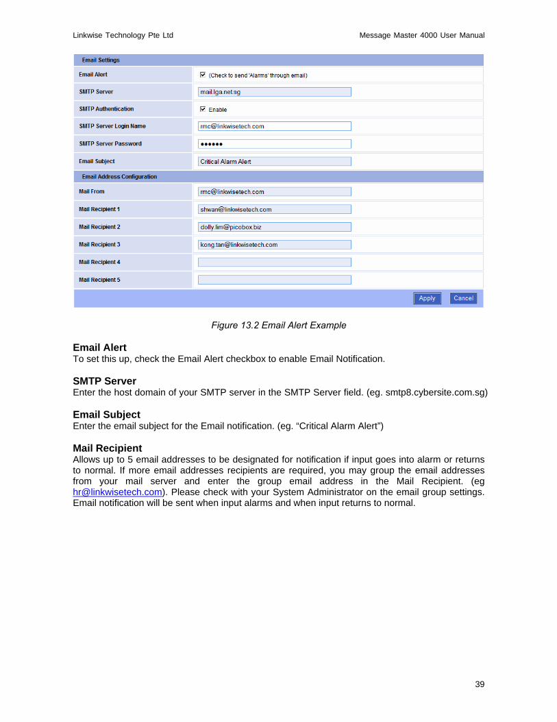
Figure 13.2 Email Alert Example Email Alert To set this up, check the Email Alert checkbox to enable Email Notification. SMTP Server Enter the host domain of your SMTP server in the SMTP Server field. (eg. smtp8.cybersite.com.sg) Email Subject Enter the email subject for the Email notification. (eg. “Critical Alarm Alert”) Mail Recipient Allows up to 5 email addresses to be designated for notification if input goes into alarm or returns to normal. If more email addresses recipients are required, you may group the email addresses from your mail server and enter the group email address in the Mail Recipient. (eg [email protected]). Please check with your System Administrator on the email group settings. Email notification will be sent when input alarms and when input returns to normal.

Linkwise Technology Pte Ltd Message Master 4000 User Manual
40
Chapter 14: Administration Page This page gives you administrator control over RMC.
Figure 14.1 Admin Page

Linkwise Technology Pte Ltd Message Master 4000 User Manual
41
Change Device ID This entry is for the Administrator to assign a unique name to RMC. It accepts up to 15 alphanumeric characters. The Device name will be SMS along with other information when an alarm is triggered. It is advisable to change the Device ID according to the location or site name, as the user will still know where the SMS alert is from which location even if there is a change in the device Sim card number.
Figure 14.2 Device ID Change Date & Time Enter the new date and time in this field. The date and time should use the following format: date/month/year (dd/mm/yyyy) and hour:minute:second (hh:mm:ss). For setting the real-time clock of RMC. Date and time information are also sent to mobile phone(s) when an alarm is triggered.
Figure 14.3 Date & Time
NTP server To enable time synchronize with NTP server. Set the Host or IP address of the NTP server to be used. Select the GMT from the drop down box and check the Enable checkbox. The NTP will synchronize the time with the server that has less number of the stratum.
Figure 14.4 NTP Server
Change Administrator Password This feature enables administrator to change the username and password for the Administrator account. Ensure that the setting is recorded and kept in a safe place. Entering wrong username and password will prevent access to RMC menu. Contact your distributor if this happens. This login account for a user does have full administrator privileges. The default username and password for this user account is “admin”. To change the Administrator password, inside this field under Current Password, type the current administrator password, followed by a new password in both New Password and Verify Password fields, then click on the Apply button.

Linkwise Technology Pte Ltd Message Master 4000 User Manual
42
Figure 14.5 Change Administrator Password
Change Guest Password This feature enables administrator to change the password for the Guest account. The Guest account does not have administrator privileges. Guest user is not allowed to make any changes in configuration or view all the administrative pages. The default username and password for this user account is “guest”. To change the Guest password, type a new password in both New Password and Verify Password fields, then click on the Apply button.
Figure 14.6 Change Guest Password Network Configuration This setting is self explanatory. Care is to be exercised in setting the IP address and subnet mask values. Incorrect IP address /subnet mask setting will render RMC inaccessible from the network. Invalid IP/Subnet range will also cause RMC to be inaccessible from the network. RMC do have error trapping and will warn of any invalid settings. If for some reason, the trapping misses and the invalid values are accepted by the unit and cause network connection difficulties, contact your distributor for assistance.
Figure 14.7 Network Configuration

Linkwise Technology Pte Ltd Message Master 4000 User Manual
43
IP Address You can change the IP address of RMC using this option. Enter the new IP address. Subnet Mask Set the subnet mask of the device using this option. Gateway Set the default gateway of the device using this option. For the example below, user can change the IP Address manually to other address other then the default IP address.
Figure 14.8 Change IP Address PBNet Service Port This is a TCP/IP port setting. It is used for communication with other RMC units or WEC expansion units. If other RMC units or expansion units are present, ensure that all RMC and any expansion units are set to the same service port. Default port number is port 9994. User can choose to use other port numbers that are not used by any PC or equipments on the network. Example, port 80.
Figure 14.9 Server Commns-Check Server Comms-Check When there are multiple RMC (RMC1 and/or RMC2) on the network, user can configure the controllers to check on each other’s connectivity. For example, upon lost communications with Server 1 eg 192.168.1.20, RMC will send an SMS stating communication timeout with 192.169.1.20. Up to three servers can be assigned. Default port number being used is port 9994.
Linkwise Technology Pte Ltd Message Master 4000 User Manual
44
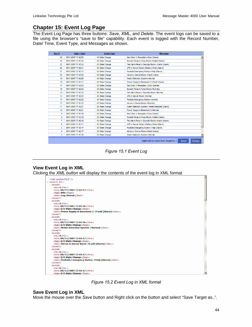
Chapter 15: Event Log Page The Event Log Page has three buttons: Save, XML, and Delete. The event logs can be saved to a file using the browser’s “save to file” capability. Each event is logged with the Record Number, Date/ Time, Event Type, and Messages as shown.
Figure 15.1 Event Log View Event Log in XML Clicking the XML button will display the contents of the event log in XML format
Figure 15.2 Event Log in XML format
Save Event Log in XML Move the mouse over the Save button and Right click on the button and select “Save Target as..”.
Linkwise Technology Pte Ltd Message Master 4000 User Manual
45
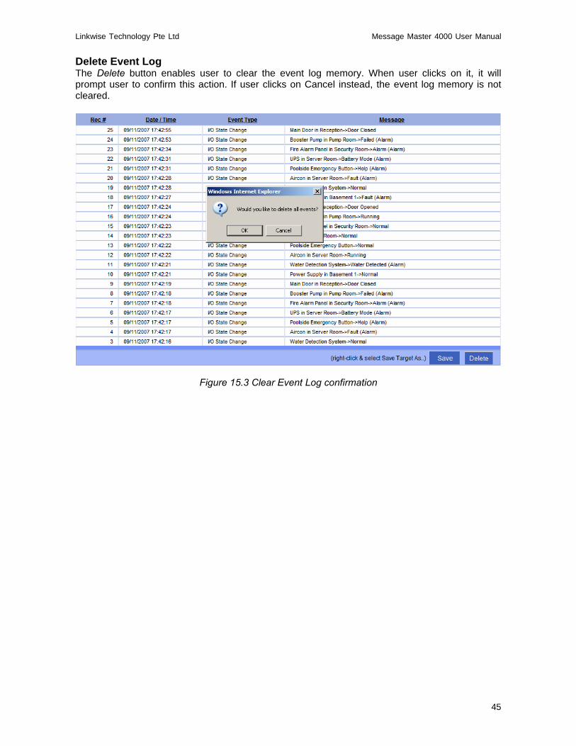
Delete Event Log The Delete button enables user to clear the event log memory. When user clicks on it, it will prompt user to confirm this action. If user clicks on Cancel instead, the event log memory is not cleared.
Figure 15.3 Clear Event Log confirmation

Linkwise Technology Pte Ltd Message Master 4000 User Manual
46
Chapter 16: Help Page RMC allows a number of important functions to be accessed and controlled remotely via SMS by the listed and authorized mobile phones. The four categories of users (Operation, Escalation, Forward, and Authorizer) have specific rights in the use of various remote control functions.
Figure 16.1 Help Page

Linkwise Technology Pte Ltd Message Master 4000 User Manual
47
Note: * All SMS remote commands, Input(X), Output(Y), and Analog Input(AI) are non-case sensitive * Space is necessary after each command and parameters passed are separated by commas * Forward and Operation group have same rights Two important arguments are used in conjunction with the action commands. [?] Is a query and [#] is a set argument.
Example: ?ROP is to query the device: Read Operation Phone #WOP is to write to the device: Write Operation Phone
Note: If a command sent to RMC does not match the required format or is invalid, RMC will not respond to the querying mobile phone and no action is taken by it. Similarly, if any unauthorized mobile phones try to query a status or to do a set command, it will also not respond to that mobile phone. Query Mobile Phone Numbers An authorized person can perform query and hanging of Operation, Forward, and Authorizer mobile phone numbers stored in the unit’s memory.
Rights SMS Remote Action SMS Command Sample
Command Comment Operation Authorizer
Query Operation number(s) ?rop X ?rop A X = Group identifier from A –H
Query whole group yes yes
Query Escalation number(s) ?rep X ?rep A X = Group identifier from A / B
Query whole group Yes yes
Query Forward number ?rfp N ?rfp 1 N = Forward phone 1
Query forward number yes yes
?rap N ?rap 1 Query Authorizer number(s) ?rap ?rap
N = Authorizer phone 1-3 Query whole group leave N empty
no yes
Table 16.1 Query Mobile Phone Numbers
Phone Management An authorized person can remotely phone manage the Operation, Forward, and Authorizer mobile phone numbers stored in the unit’s memory. The Authorizers are allowed to perform Addition, Replacement, and Deletion of mobile phone numbers remotely using SMS commands.
Rights SMS Remote Action SMS Command Sample Command Comment
Operation Authorizer
#wop XN,phn_number #wop A1,98765432 Add / Delete /
Replace Operation number #wop XN, #wop A1,
X = Group identifier from A -H N = Operation phone 1-5 Delete number leave phn_number empty
no yes
#wep XN,phn_number #wep A1,98765432 Add / Delete /
Replace Escalation number #wep XN, #wep A1,
X = Group identifier from A or B N = Operation phone 1 - 5 Delete number leave phn_number empty
no yes

Linkwise Technology Pte Ltd Message Master 4000 User Manual
48
#wfp N,phn_number #wfp 1,98765432 Add / Delete / Replace Forward number #wfp N, #wfp 1,
N = Forward phone 1 Delete number leave phn_number empty
no yes
#wap N,phn_number #wap 1,98765432 Add / Delete / Replace Authorizer number #wap N, #wap 1,
N = Authorizer phone 1-5 Delete number leave phn_number empty
no yes
Table 16.2 Phone Management
Query IO & system status Operation and authorized users can query the status of Inputs/outputs and perform system checks. RMC will reply the current state of the Input and Output, and the System status using the respective commands.
Rights SMS Remote Action SMS Command Sample
Command Comment Operation Authorizer
?ip N ?ip 1 Query Input status
?ip input_name ?ip ups
N = input 1 - 8 input_alarm = none or open or close System reply with Input state
yes yes
?op N ?op 1 Query Output status
?op output_name ?op siren
N = output 1 - 4 output_name = output description System reply with Output state
yes yes
?ai N ?ai 1 Query Analog Input status
?ai analog_input_name ?ai room temp
N = analog input analog_input_name = analog description System reply with Analog reading
yes yes
Query all I/Os ?io ?io System reply with IO status N = Normal or A = Alarm
yes yes
Query system status ?syscheck ?syscheck System reply with Telco signal
strength yes yes
Table 16.3 Query IO & system status
Output Control Operation and authorized users can switch the 2 outputs ON, OFF or Pulse by sending the commands below. Users can also enable or disable the logic specify in the Output Config page.
Rights SMS Remote Action SMS Command Sample
Command Comment Operation Authorizer
Switch on output #on output_name #on siren output_name = output description
yes yes

Linkwise Technology Pte Ltd Message Master 4000 User Manual
49
Switch off output #off output_name #off siren output_name = output description
yes yes
Pulse output #ps output_name #ps siren output_name = output description
yes yes
Table 16.4 Output Control
Repeat Configuration Authorized users can change the SMS alarm repeat settings sending the commands below. To cancel repeat sending, any mobile phone from the operation or forward must acknowledge to RMC by replying the acknowledge command (#ack).
Rights SMS Remote Action SMS Command Sample Command Comment
Operation Authorizer
#rpt 2 N = number of times SMS repeat Set number of
repeat times #rpt N
#rpt 0 0= disable repeat
no yes
Set repeat interval #rpt-time N #rpt-time 5 N = repeat time interval in
minutes no yes
Query repeat status ?rpt ?rpt System reply with repeat
interval yes yes
Acknowledge repeat alarm #ack #ack
System reply with Ack received. SMS repeat stops
yes yes
Table 16.5 Repeat Configuration
Remote SMS command Benefits With the remote command functionality above it saves time and effort.
o Re-assigning of operation personnel, a change of mobile phone number is also common. Rather than having to physically go to the installation site with a notebook computer, the authorized personnel can perform the change from anywhere using their mobile phone. Where there are many installed sites this becomes very efficient.
o Remotely add, change or clear any setting of repeat time interval in RMC memory.
Flexibility to change / clear the repeat SMS, once users are familiar with the monitored site and wish to stop receiving repeat SMS . Or a new site that you wish to receive the repeat SMS. All these control are just as simple by using the above remote command from anywhere using you mobile phone.
Linkwise Technology Pte Ltd Message Master 4000 User Manual
50
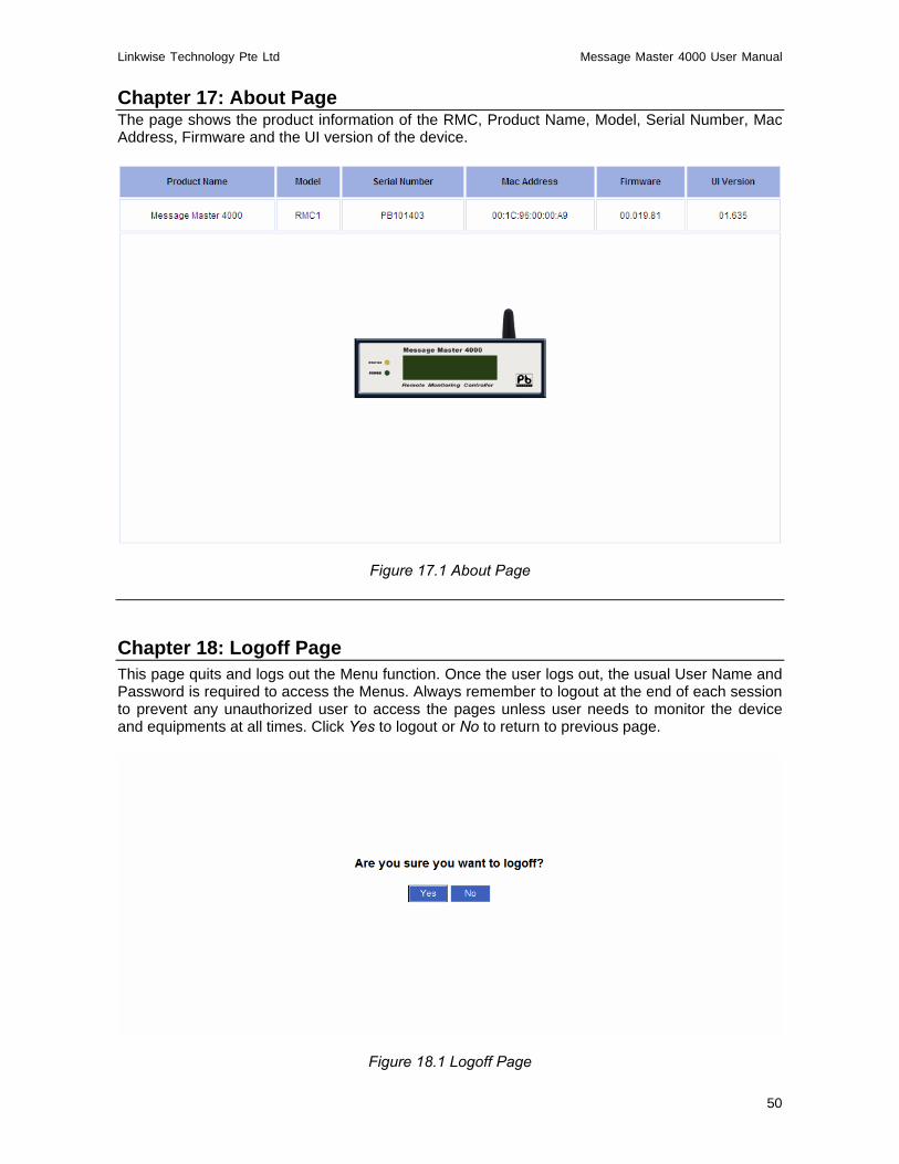
Chapter 17: About Page The page shows the product information of the RMC, Product Name, Model, Serial Number, Mac Address, Firmware and the UI version of the device.
Figure 17.1 About Page
Chapter 18: Logoff Page This page quits and logs out the Menu function. Once the user logs out, the usual User Name and Password is required to access the Menus. Always remember to logout at the end of each session to prevent any unauthorized user to access the pages unless user needs to monitor the device and equipments at all times. Click Yes to logout or No to return to previous page.
Figure 18.1 Logoff Page

Linkwise Technology Pte Ltd Message Master 4000 User Manual
51
Appendix A Setting Static IP Addresses First, you need to know the IP address and subnet mask settings for RMC. To find these, power up the RMC and after about 5 seconds, the display will show its IP address and subnet mask settings. The default values are:
Figure 19.1 Default IP Address
That is, the default IP address is 192.168.1.10 and the default subnet mask is 255.255.255.0. This means the IP address of your PC may be set in the range 192.168.1.1 to 192.168.1.254 inclusive but obviously excluding 192.168.1.10, which is the address for the RMC unit. For the examples below, we are using the address 192.168.1.100 for the PC. Setting a Static IP Address for Windows 98 Step 1. Click on the Start button and select Control Panel. (Figure 19.2)
Figure 19.2 Start Button
Step 2. In the Control Panel window, double-click the Network icon. (Figure 19.3)
192.168.1.10 255.255.255.0

Linkwise Technology Pte Ltd Message Master 4000 User Manual
52
Figure 19.3 Control Panel
Step 3. You will see the Network settings window (Figure 19.4). Select the correct TCP/IP ->
Ethernet Adapter (Ethernet card) configuration. The figure below only shows an example; the correct one in your situation will be the TCP/IP-to-Ethernet setting for the Ethernet card that is connected to the RMC. Select the correct adapter and click the Properties button.
Figure 19.4 Network Settings
Step 4. You will then see the TCP/IP settings window as shown in (Figure 19.4). Enter the fixed IP
address for the PC. If you are keeping the default IP settings for the RMC and are using it in a standalone environment, a suitable setting for the PC is an IP address of

Linkwise Technology Pte Ltd Message Master 4000 User Manual
53
192.168.1.100 and a subnet mask of 255.255.255.0. Click OK to close the window and accept the changes.
Figure 19.5 TCP/IP Settings
Step 5. Restart the PC for the settings to take effect. (Figure 19.6)
Figure 19.6 Shutdown Menu

Linkwise Technology Pte Ltd Message Master 4000 User Manual
54
Setting a Static IP Address for Windows 2000 / Windows XP Step 1. Right click on the My Network Places icon on your desktop and select Properties.
Figure 19.7 My Network Places icon
Step 2. Right click on the Local Area Connection icon and select Properties.
Figure 19.8 Local Area Connection icon
Step 3. Double-click on Internet Protocol (TCP/IP) and you will see the window. (Figure 19.9)
Figure 19.9 IP Configuration
Step 4. Select Use the following IP address and in the IP address field, enter a suitable IP address
for your PC, such as 192.168.1.100. This is your PC’s static IP address. In the Subnet

Linkwise Technology Pte Ltd Message Master 4000 User Manual
55
mask field, enter 255.255.255.0. Leave the Default gateway field blank. You may leave the Obtain DNS server address automatically as it is.
Figure 19.10 IP Configuration Example Step 5. Click the subsequent OK buttons to accept the settings and to close the windows until you
get back to the desktop. Your IP settings are now correct.
- End of Document -


