16

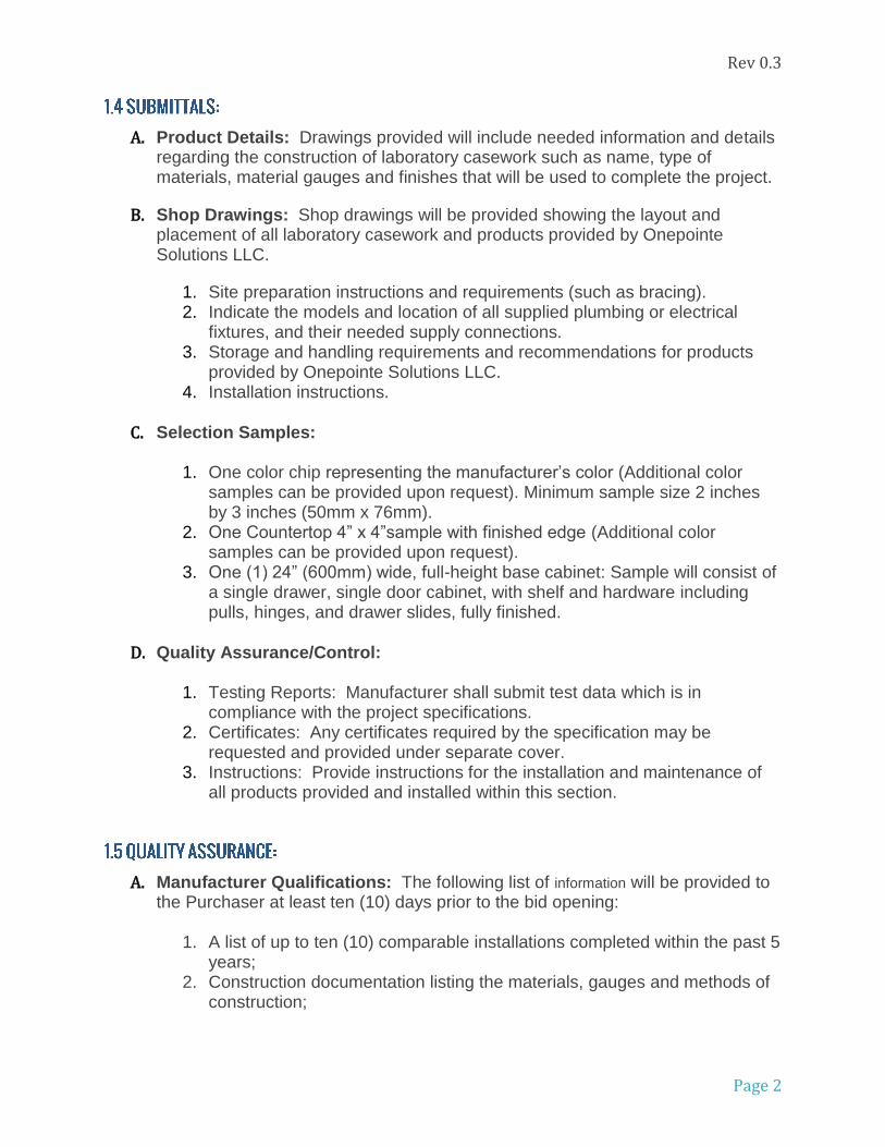
LIGHT GREY WINDOW GREY BASALT GREY OYSTER WHITE
LIGHT IVORY BEIGE GREY JET BLACK (GLOSS) JET BLACK (MATTE)
JET BLACK (TEXTURE) WHITE PAPYRUS WHITE STONE GREY
GENTIAN BLUE GREEN BLUE BLUE GREEN FLAME RED
BLACK RED
CUSTOM COLORSAVAILABLE UPON REQUEST

SpecificationsAprons
Back Panels
Bottom Panels
Drawer/Door Outer Panel
Door Inner Panel
Drawer Boxes
16ga.
20ga.
18ga.
18ga.
20ga.
20ga.
Legs - 2" sq. tube
Shelves
Side Panels
Table Frame
Stainless Steel Shelf Clips
14ga.
18ga.
18ga.
14ga.
18ga.
All surfaces are painted with chemical resistant powder

Rev 0.3
The following specifications are provided to define and clarify areas related to the quality, warranty, and installation of products provided by Onepointe Solutions LLC,
A. Laboratory Grade Casework B. Mobile Modular Casework C. Mobile Tables & Workstations D. Shelving
A. Division 09 Section 65 13, “Resilient Base and Accessories” B. Division 11 Section 53 00, “Laboratory Equipment” C. Division 12 Section 31 00, “Manufactured Metal Casework” D. Division 12 Section 36 00, “Countertops” E. Division 13 Section 21 00, “Controlled Environment Rooms” F. Division 22 Section 40 00, “Plumbing Fixtures” G. Related Work to Be Performed by Others:
1. Installation of any electrical fixtures or outlets that require hard wiring or
the running of wires. 2. Installation of any plumbing fixtures attached to the casework or
countertops. 3. Connections of any service lines for gas, plumbing or electrical fixtures or
outlets.
A. SEFA 8: Casework recommended practice B. ADA (ATBCB ADAAG): Americans with Disabilities Act Accessibility Guidelines
Americans with Disabilities Act (ADA)
Rev 0.3
Page 2
A. Product Details: Drawings provided will include needed information and details regarding the construction of laboratory casework such as name, type of materials, material gauges and finishes that will be used to complete the project.
B. Shop Drawings: Shop drawings will be provided showing the layout and placement of all laboratory casework and products provided by Onepointe Solutions LLC.
1. Site preparation instructions and requirements (such as bracing). 2. Indicate the models and location of all supplied plumbing or electrical
fixtures, and their needed supply connections. 3. Storage and handling requirements and recommendations for products
provided by Onepointe Solutions LLC. 4. Installation instructions.
C. Selection Samples:
1. One color chip representing the manufacturer’s color (Additional color
samples can be provided upon request). Minimum sample size 2 inches by 3 inches (50mm x 76mm).
2. One Countertop 4” x 4”sample with finished edge (Additional color samples can be provided upon request).
3. One (1) 24” (600mm) wide, full-height base cabinet: Sample will consist of a single drawer, single door cabinet, with shelf and hardware including pulls, hinges, and drawer slides, fully finished.
D. Quality Assurance/Control:
1. Testing Reports: Manufacturer shall submit test data which is in compliance with the project specifications.
2. Certificates: Any certificates required by the specification may be requested and provided under separate cover.
3. Instructions: Provide instructions for the installation and maintenance of all products provided and installed within this section.
A. Manufacturer Qualifications: The following list of information will be provided to the Purchaser at least ten (10) days prior to the bid opening:
1. A list of up to ten (10) comparable installations completed within the past 5 years;
2. Construction documentation listing the materials, gauges and methods of construction;

Rev 0.3
Page 3
3. Independent laboratory test reports that include information on cabinets and top finish performance that have been conducted within the last two years
4. A summary of Onepointe Solutions LLC. Quality processes used to assure product conformance.
B. Mock-Ups:
1. If mockups are required, they will be quoted and produced to a high
quality standard for owner approval. Area mockups can be priced for use within the project or quoted separately.
2. Do not proceed with remaining work until installation is approved by Purchaser.
a. Install base cabinet with specified hardware. b. Install wall cabinet with specified hardware. c. Install workstation(s)
A. Packaging, Shipping, Handling and Unloading
1. Packaging: Products will be wrapped sufficiently to protect finished surfaces from dirt or damage during shipping, delivery and installation.
2. Delivery: Casework delivery will only take place after painting, all utility rough-ins and related construction are completed that could otherwise damage, or deteriorate casework in installation areas.
3. Handling: Care should be exercised at all times when moving delivered product. Palletized product should be moved on its shipping skids and only unpackaged at the time of installation to avoid scuffs, discoloration or other damaged to finished product. Until the product is installed, any packaging placed on product for shipping will remain in place to avoid accidental damage.
B. Acceptance at Site: Casework will not be delivered or installed until the
conditions specified under Installation (Part 3) have been met.
C. Storage: Casework is to be stored in the area of installation. If before the installation, it is necessary for casework to be stored in a location other than the intended installation area, the conditions of the storage location will need to meet the requirements listed under the Project Site Conditions article of this section.
D. Waste Management and Disposal: The supplier of the laboratory casework is
responsible for removing any waste resulting from the installation of, or work pertaining to laboratory casework. Installation crews will leave the project site

Rev 0.3
Page 4
clean and free of any packing materials used in shipment and storage. Trash container(s) to be provided by others.
A. Building must be totally enclosed (This includes but is not limited to: Windows and Doors installed, and the location must be weather tight);
B. An operational heating and cooling system that maintains a consistent temperature and humidity at normal levels for occupancy of the space.
C. Nearby and related work shall be complete; D. Ceiling, lighting and any overhead ductwork must be installed and completed; E. Site must be free of additional construction such as painting, taping and floating,
drywall work or other items that could damage or mark finish of installed product; F. Required bracing must be installed properly and be ready for casework
installation.
A. Provide a written warranty that all work performed under this section shall be free from defects of materials, finish and workmanship for a period of two (2) years from date of shipment. Defects in materials and workmanship that may develop within this time are to be corrected by the manufacturer. Defects include, but are not limited to:
1. Product shift, or the failure of attachment to wall, floor, or ceiling (when installed by Onepointe Solutions LLC.)
2. Weld or structural failure 3. Warping or unloaded deflection of components 4. Failure of hardware
B. The warranty of products of another manufacturer, and sold by Onepointe
Solutions LLC, are limited to the warranty extended by that manufacturer to Onepointe Solutions LLC.

Rev 0.3
Page 5
A. Acceptable Manufacturer:
Onepointe Solutions LLC. Direct Phone: (866) 612-7312 Email: [email protected]
B. Substitutions: Are required to meet all specification requirements and have prior written approval.
C. Requests for substitutions: All requests will be considered in accordance with
provisions of Section 01.
A. Sheet Steel: Mild steel, cold rolled furniture grade to requirements of ASTM A1008/A1008M, Grade C or higher, with smooth surfaces to furniture quality.
B. Galvanized Sheet Steel: Commercial quality galvanized sheet steel to ASTM 653, Designation Z275.
C. Stainless Steel: 1. Sheet: ASTM A240, type 304 or 316 alloy. 2. Finish: Unless otherwise indicated, AISI No. 3 or 4 brushed Finish
D. Glass: Clear float, .125” (5mm) thick, conforming to ANSI z97.1, glazing quality.
E. Acrylic: Clear Acrylic .125” (5mm) thick conforming to ANSI z97.1 for use as a
safety glazing material in buildings.
F. Resilient Base and Adhesive: Base cabinets to be designed to work with 4” high base molding provided by others. Metal fillers for non-level floors shall be provided as required after installation and shall be added to the contract as agreed upon.
A. Materials and Thickness: Use the following minimum steel thicknesses for furniture manufacturing:

Rev 0.3
Page 6
12 Ga (2.8mm) under mount sink supports, caster plates for mobile cabinets, and slotted uprights.
14 Ga (1.9mm) top support plates, and legs for leg sets and bolt together tables.
16 Ga (1.5mm) end pedestals, apron rails, knee space panels, reagent uprights, pull out trays, pull out shelves, lower steel table shelves, cross-rails and steel table tops.
18ga (1.2mm) door fronts, cabinet floor, cabinet sides, vertical front members, cabinet toe kick, service cover panels, inner cabinet panels, cabinet shelves, and hat channel supports.
20ga (0.9mm) for drawer backs, drawer boxes, drawer sides, door backs, removable back panels, filler panels, shelf clips, wall case shells, wall case tops, wall case bottoms and slip joints.
B. Cabinet Frame:
1. Provide one-piece die-formed cabinet bottom construction with return side flanges turned down.
2. Cabinet bottoms shall be turned down at front to form .75” (19mm) floor to accept toe kick, and turn down 4.75” (1200mm) at back with 2” (50mm) return to form back lower member of cabinet base and mounting rail for leveler weld nuts. Provide punched .875” (22mm) dia. Corner holes for access to levelers. It shall be possible to access levelers from above cabinet without removing drawer supports.
3. Side panels are constructed from 18ga (1.2mm) steel with a .75” (19mm) return in the front and a 1.5” (40mm) return in the rear to form the front and rear structural members of the cabinet frame. Inner side panels are constructed from 18ga (1.2mm) steel and have a 1” (27mm) return front and back to fit inside outer panel and complete front, back and side frames of cabinet. Inner panels are punched to support drawers and shelves where applicable.
4. Doors and drawers shall be full inlay and rest on return of inner panel and floor panel. Top cross rails are provided for cabinets with two doors or multiple drawers to provide additional support.
5. Top horizontal front framing is turned down 1” (27mm) with a 1.38” (33mm) return flange in the front to create box top frame and provide a surface to secure locking tab for doors and drawers. Rear of top framing has a 1.5” (38mm) turn down with a .38” (9mm) return flange to form top rear framing member.
6. Top horizontal plate contains .28” (7mm) dia. holes for securing top material.

Rev 0.3
Page 7
7. Cabinetry toe space shall be 3” (75mm) deep x 4” (100mm) high and shall act as a total enclosure to bottom of cabinet. Toe space section shall key up into “U” shaped front floor member and act as reinforcement. Toe space, front floor of cabinet and side panel sections shall be welded together forming one structural member.
8. The toe space members, side gable returns, and back lower member shall form all welded structural corner to accept 3/8 (10mm) leveling bolts.
9. Cabinet construction shall be MIG welded (TIG welded on stainless) to form a strong well-fitted, one-piece unit.
C. Cabinet Hardware:
1. Pulls: Provide handles for drawers and hinged doors in [4” (100mm) satin finish aluminum] or [4” (100mm) tubular stainless steel]
2. Door Hinges: Provide concealed half overlay hinges [zinc coated] screwed into door and fastened to cabinet side with 2 #8 x.375 metal screws.
3. Locks: 5-disc tumbler, removable core lock with single cut key. 90-degree cam turn on all locks with key removable in both locked and unlocked position. 200 key changes possible
D. Base Cabinet Components:
1. Provide removable back panels for cupboard base cabinets. Provide partial back panels 12” (300mm) in height to accommodate plumbing at sink units.
2. Shelving edges are turned down on sides .75” (18mm), and turned down front and back .875” (22mm) with returns under front and back .38” (9mm).
3. Doors:
a. Fabricate doors of two metal panels, .875” (22mm) thick when assembled. Reinforce hinge side of door adequately with u shaped hinge channel to prevent sagging or pulling of fasteners. Secure recessed hinges to cabinet with #8 metal screws. Provide each door with two rubber bumpers.
b. Doors, drawers, and back panels shall be replaceable in the field without requiring special tools.
c. All standard double door cabinets shall be designed without center stiles to maximize access to the cabinet.
d. Hinged glass doors shall be fabricated as in Para. 2.3.D.3.a with the modification of a window in the outer and inner panels for installation of glass as per Para. 2.2.D. 20ga (.9mm) channels are used in the door to secure glass internally in the door. Rivets are used to secure

Rev 0.3
Page 8
channels to inner door panel. No externally visible fasteners are permitted.
e. Hinged Plexiglass doors shall be fabricated as in Para. 2.3.D.3.d with the modification that Plexiglass (Para. 2.2E) is used instead of glass for taller doors for strength.
4. Drawers:
a. Fabricate drawer fronts of 20ga (.9mm) metal panels. The exterior drawer front shall have a channel formation at the top edge with fully finished return edges to form finished drawer front when secured to drawer box. Drawer front has lip to fit over inside box on top edge and sides and to lock into position at bottom with rivets to form a rigid one piece .875” (22mm) thick drawer front.
b. Drawer slide systems shall be designed to eliminate metal surface to surface contact and reduce side play while incorporating a self-closing action for 6” (150mm) of drawer travel. Drawer slides are low maintenance ball bearing slides.
c. Provide drawer operation on full extension drawer slides, load capacity 100 lbs. (45kg).
d. Drawer body shall consist of three-piece construction, the first piece including the bottom, back, and inner front flanged end. The other two pieces are the box sides which shall be riveted to the interior drawer front head and drawer box back to form a rigid single inner drawer box. Drawer bodies shall have a reinforcing bend on top edges.
e. Provide built-in stops to prevent inadvertent removal of drawers, with allowance for drawer to be removed by lifting a release tab on the drawer slide and pulling drawer out.
f. Provide drawer pulls in center location of drawer face. Two handles shall be provided on units 36” (914mm) and larger
5. Mobile Cabinets: Mobile cabinets shall be the same construction as fixed
base cabinets with the following modifications:
a. Toe kick space shall be eliminated. b. Cabinet underside shall be reinforced with a 12ga (1.9mm) steel pan
to provide caster mounting points. c. Counterweights shall be provided to prevent the cabinet from tipping
when one drawer is opened. d. Drawers shall be rated at 50lbs (23kg) maximum. e. Four casters shall be provided with a load rating of 150lbs each.
6. Leg Sets:
a. Leg sets shall consist of two 2” (50mm) square metal tubular legs
complete with levelers.

Rev 0.3
Page 9
b. Leg sets shall be provided with 1.5” (30mm) x 1.5” (30mm) steel rail centered 4” (100mm) up from bottom of legs.
c. Top of leg sets are joined by a 14ga, 4” (100mm) tall cross rail with .28” (7mm) punched holes for securing top. Rail includes mounting tabs to mount to horizontal rails or apron assembly.
7. Apron Drawer Assembly:
a. Apron drawer assembly shall be fabricated from metal channel
shaped skirting panels of modular widths the same as standard base cabinets. Rails 4” (95mm) high channel ends shall be turned to fit into end mounting brackets. Drawer suspension framing shall be mechanically fixed to channels, welded integrally with front and back channel sections formed into a rigid one-piece frame.
b. Where called for, drawers located in table aprons shall be supplied in a maximum width of 15” (381mm) with a two drawers option available in aprons 48” (1219mm) and wider. Drawer suspension shall be with ball bearing slides and self-closing action, custom manufactured 18ga (1.2mm) suspension system.
8. Knee Space Rails:
a. Knee space rail units shall be fabricated from a single metal channel-
shaped skirting panel in modular widths the same as standard base cabinets. Channel ends shall be turned to fit into end mounting brackets. Rails are 4” (100mm) high.
9. End Panels:
a. End Panels shall consist of two 16ga (1.5mm) side panels welded
together to form a strong rigid unit. b. End Panels shall be 2” (50mm) thick and be designed to accept a
Knee Space Rail or Apron. c. End Panels shall be provided with two leveling devices.
10. Filler Panels:
a. Fabricate front filler panels complete with flanges on both sides and a 3”
(75mm) x 4” (100mm) toe space along the working face. b. Scribe filler panels shall be flanged on one side and flat on the other, to
be cut on jobsite to suit wall conditions, and shall fit into double angles secured to the wall. No visible mounting screws permitted.
c. Corner filler panels shall be a two-piece construction, one fixed upper panel and the other forming the toe kick. Each shall have flanges and a riveted 3” (75mm) x 4” (100mm) toe space filler to form a one-piece unit.

Rev 0.3
Page 10
d. End closing filler panels shall be flanged on one side 1” (25mm) and secured to back of cabinet. The edge extending to wall shall be flat and fit into a double angle secured to wall. No visible mounting screws permitted.
E. Floor/Wall Cabinet Components:
1. Materials and Thicknesses: Use the following standard steel thicknesses for this furniture manufacturing: a. 18ga (1.2mm) prime grade furniture steel for sides, top, back, bottom,
and bases on tall storage cabinets. b. 20ga (.9mm) prime grade furniture steel for dust caps.
2. Wall Storage Cabinets Open Type:
a. Cabinet sides and back shall be formed of outer 20ga (1mm) panels
welded to a pan 20ga (1mm) floor and top. Inner 20ga (1mm) U shaped side panels include punched mounting holes for shelf clips.
b. Provide a shelf (additional shelves for each unit available for purchase) with edges turned down on front and back .875” (22mm) and .635” (17mm) on left and right sides and a return on the front and back of .38” (8mm). Provide shelf adjustment on 1.5” (38mm) increments for full height of cabinet interior. Provide a minimum of two stainless shelf clips per shelf.
c. Install bumpers on vertical reinforcement members of the cabinet frame.
3. Wall Storage Cabinets; Framed Glass Doors: a. Fabricate cabinet the same as in Para. 2.3.E.2.a. above. b. .125” (5mm) glass shall be provided for frame glass doors as described
in Para. 2.2.
4. Wall Storage Cabinets: Hinged Metal Doors: a. Fabricate cabinets as specified in Para. 2.3.E.2.a. b. Hinged metal doors shall be as specified in Para. 2.3.D.3.
5. Floor Storage Cabinets; Open Type: a. Fabricate cabinet bottom as specified in Section 2.3.B.1., 2.3.B.2. and
2.3.B.3. Provide a finished floor full width and depth of interior with return flanges turned down on all four edges in both upper and lower sections and welded in place. Fabricate cabinet floor flush with front flange.

Rev 0.3
Page 11
b. Provide built-in toe space 4” (100mm) high extending full width of cabinet recessed back 3” (75mm) from front face with a .375” (10mm) diameter steel threaded bolt type levelling device in each corner.
6. Floor Storage Cabinets - Hinged Metal Doors:
a. Construct cabinets as per Para. 2.3.B. and 2.3.C., and modified as in
Para. 2.3.E.5.a. b. Hinged metal doors as per Para. 2.3.D.3.
7. Floor Storage Cabinets – Hinged Glass Doors:
a. Construct cabinets as per Para. 2.3.B. and 2.3.C. b. Hinged Acrylic Doors as per Para. 2.3.D.3.e
8. Dust Cap: a. Dust caps shall be fabricated from 20ga (1.2mm) steel, and shall mount
flush with the front edge of the cabinet and extend back at an angle of 25 degrees to a point perpendicular to the rear of the cabinet. Ends shall be finished and flanged so as to allow attachment to the cabinet below.
9. Steel Furniture Finish:
a. Paint performance data is available upon request. b. All stainless furniture in this section shall be constructed of stainless
steel with a #3 or #4 brushed finish. Grain direction shall be horizontal except where cabinet dimensions do not permit.

Rev 0.3
Page 12
Installer Qualifications:
1. Installer shall have a minimum of five years of experience in installation or application of a similar casework product as this project.
2. Installer shall be authorized by Onepointe Solutions LLC. Warranty will be void if unauthorized installer executes the installation.
Site Preparation requirements: Casework will not be delivered or installed until the following conditions have been met:
1. Building must be fully enclosed and weather-tight; 2. An operational heating and air conditioning system must be in place to
maintain both temperature and humidity levels at the same level as when the space is occupied;
3. Ceiling, lighting and any overhead ductwork must be installed and complete.
4. Site must be free of any further construction that could damage or blemish the finish of the product.
5. Required bracing must be properly installed in the correct locations for installation to proceed.
NOTE: In the event that any of these requirements for installation are not met at the time of requested delivery, the general contractor or owner must provide Onepointe Solutions LLC with a letter of deviation that releases the manufacturer from any responsibility or liability from any damage to the products cause by unfavorable conditions on the job site.
A. Casework Installation:
1. Casework components will be set plumb, straight and square. Concealed shims will be used as needed.
2. Cabinets in continuous runs shall be fastened together flush, and tight with misalignment of adjacent units not to exceed 1/16 of an inch.

Rev 0.3
Page 13
3. Wall casework shall be secured to solid material, not lath, plastic or gypsum board. Where this is not possible, an appropriate wall toggle or anchor bolt system will be used.
4. Top surfaces shall be joined in one level plane. Joints will be flush and gaps shall not exceed 1/8 of an inch between the tops.
5. Casework will be adjusted and aligned to allow for straight and secure connection to each other and proper operation of all doors and drawers with no binding or warpage.
B. Countertop Installation:
1. Countertops will be fabricated in lengths according to design drawings, with
ends fitting tightly and sealed with corrosion resistant sealant. 2. Where possible, seams shall be factory prepared and have no need for in-
field preparation of top and edge surfaces. 3. Seams shall be sealed smoothly, any surface blemishes removed and
entire surface thoroughly cleaned.
A. Ensure all products are blemish free and of matching finish. Damaged or defective product will be removed or repaired as needed.
B. All finished surfaces are to be cleaned, including drawers and cabinet shelves, and touched up as necessary.
C. Counter tops shall be cleaned and free of any blemishes or streaking.
A. Counter tops and ledges shall be covered for the remainder of the construction process.
B. Examine casework for damaged or soiled areas; replace, repair, and touch-up as required.
C. Touch-up, repair or replace damaged products before Substantial Completion.


