Page 1
Metallic Interconnects for Proton Ceramic Fuel Cells
Oxidation behavior and transport properties
under simulated fuel cell conditions
Anders Werner Bredvei Skilbred
Dissertation for the degree of Philosophiae Doctor
Centre for Materials Science and Nanotechnology (SMN)
Department of Chemistry
Faculty of Mathematics and Natural Sciences
UNIVERSITY OF OSLO
2012
Page 2
© Anders Werner Bredvei Skilbred, 2012 Series of dissertations submitted to the Faculty of Mathematics and Natural Sciences, University of Oslo No. 1279 ISSN 1501-7710 All rights reserved. No part of this publication may be reproduced or transmitted, in any form or by any means, without permission. Cover: Inger Sandved Anfinsen. Printed in Norway: AIT Oslo AS. Produced in co-operation with Akademika publishing. The thesis is produced by Akademika publishing merely in connection with the thesis defence. Kindly direct all inquiries regarding the thesis to the copyright holder or the unit which grants the doctorate.
Page 3
III
Preface
This thesis represents parts of the requirements for the degree of Philosophiae Doctor (Ph.
D.) at the Department of Chemistry, Faculty of Mathematics and Natural Sciences, University
of Oslo. This work has been funded by the Research Council of Norway, and has been carried
out at Functional Energy Related Materials in Oslo (FERMiO) at the Centre for Materials
Science and Nanotechnology (SMN).
I would like to thank my two supervisors: Reidar Haugsrud for countless hours of consultancy
services at any time of day. You have accomplished to make a handy-man from Stokke into a
published scientist. I’m impressed with your unstoppable enthusiasm, drive and care both
when it comes to science, life and skiing. I’m also grateful to Truls Norby who has guided me
with enthusiasm and interest since my first semester at UiO. Yngve Larring and Sen Mei at
SINTEF also deserve my gratitude for support and cooperation in the StackPRO project.
I would also like to express my gratitude to Prof. David J. Young and Dr. Jianqiang Zhang
who I was so fortunate to work with at the University of New South Wales, Sydney, for three
months in the autumn of 2009. My fellow PhD students Philip Speck and Thomas Gheno is
acknowledged for making my stay valuable both with regards to science and social activities.
Further, I want to thank all my brilliant colleagues and the students in the group of Solid
State Electrochemistry. You are all exceptional! A special thanks’ to Tor Svendsen Bjørheim,
Vasileios Besikiotis and Harald Fjeld for numerous discussions with and especially without
scientific content.
Page 4
IV
I’m truly grateful to my parents and the rest of my continuously growing family. Thank you
for all your support and care. I also wish to acknowledge my late grandfather, Ole Jacob, for
his important influence on my choices through life.
Further, I would like to thank Sigrid for her highly efficient distractions and unconditional
love. And finally, I will thank Kristin Elise for her love, support and patience. Together we
are strong and clever. I love you!
Oslo, September 2012
Anders Werner Bredvei Skilbred
Page 5
V
Summary
Fuel cells are expected to serve as a contribution to meet the demand for clean energy. High
temperature fuel cells such as solid oxide fuel cells (SOFC) and proton ceramic fuel cells
(PCFC) are developed for use as environment friendly energy conversion devices. However,
the successful implementation of such devices in practical applications relies on series
connections of multiple cells by so-called interconnects. During operation at high
temperatures (600 – 850 °C) facing both air and fuel, oxidation of these metallic interconnect
materials is inevitable. Formation of oxide scales will result in a reduced overall performance
of the fuel cell stack. It is therefore crucial to investigate the oxidation behavior and the
mechanisms responsible for the oxide growth on the interconnect.
This thesis consists of six chapters where the first five chapters give the basis for the work
presented in five articles. Chapter six presents a summarizing discussion which links the
results from PAPER I – IV and discusses them further, and to some extent in more
speculative terms than found suitable in the individual papers.
The applicability of a material as an interconnect for SOFC and PCFC rely on several high
temperature materials’ properties. Some of the most essential properties were investigated in
this study for the Sandvik Sanergy HT. It was found that the thermal expansion was
~12.5×10⁻⁶ /°C, a value that is regarded as suitable for SOFC and PCFC application. Further,
it was found that due to the limited formation of electrical resistive oxide scales, the area
specific resistance (ASR) measured at 700 °C was as low as ~6 mOhm×cm2 after 500 h in wet
air. This is below the generally regarded threshold value of 10 mOhm×cm2 for interconnect
materials.
Page 6
VI
The oxidation behavior of Sanergy HT was thoroughly investigated throughout this thesis. Up
to 900 °C the oxidation behavior showed parabolic kinetics, whereas at 1000 °C the oxidation
process was accelerated after ~300 h. The activation energy for oxidation (800 – 900 °C) was
found to be 272±20 kJ/mol. The oxide scales formed during oxidation in air comprised an
inner layer of Cr2O3 and an outer layer of (Cr,Mn)3O4-spinel.
Two-stage oxidation experiments were performed where the first stage of oxidation was in
18,18O2 (g) and the second stage was in 16,16O2 (g) in order to elucidate the oxide growth
mechanisms. SIMS profiles revealed that the governing transport mechanism responsible for
oxide growth was outward cation diffusion. Oxygen tracer diffusion experiments showed that
inward diffusion of oxygen was significant in the outer region of the oxide scale. As a result
of outward cation transport through the inner layer of Cr2O3 and inward oxygen diffusion
through the outer layer comprising (Cr,Mn)3O4 it was suggested that the oxide growth takes
place within the scale, likely near the Cr2O3 - (Cr,Mn)3O4 interface. However, the diffusion of
cations through the inner chromia layer is still regarded as the rate limiting mechanism for the
oxidation process.
During operation in a fuel cell the interconnect is facing air on the cathode side and fuel on
the anode side simultaneously. Such dual atmosphere exposures have been found to
significantly alter the oxidation behavior of the interconnect on the cathode side as a result of
transport of hydrogen species through the alloy. This was identified by an extensive formation
of Fe-rich oxide nodules, accompanied by localized internal oxidation and metal loss. The
influence of dual atmosphere was further enhanced by increasing the water vapor content in
the air on the cathode side. Introducing water vapor on the anode side gave however the
opposite effect; less extensive nodule formation and metal attack. Further, it was observed
that the preferred location of nodule formation and internal oxidation was related to surface
Page 7
VII
deformations of the as received samples left by cold work during fabrication, e.g. the rolling
process. Interestingly, dual atmosphere conditions was not found to have any significant
effect on the oxidation of samples coated with a metallic layer of Ce (10 nm) with Co (800
nm) on top.
The anomalous oxidation behavior of uncoated samples encountered under dual atmosphere
conditions was suggested to be a breakaway type of oxidation. The transport of hydrogen
through the alloy increases the H2O (g)/O2 (g) ratio near the metal – oxide interface and
triggers breakaway oxidation, identified by internal oxidation, metal attack and formation of
Fe-rich oxide phases observed as nodules. The reduced effect of dual atmosphere conditions
on coated samples was suggested to be due to a combination of reduced hydrogen transport
through the coated samples, and a decreased susceptibility towards breakaway oxidation as a
result of a reduction in the chromium evaporation.
Chromium nitrides are known to improve mechanical and chemical properties of alloys. It has
therefore been suggested that the formation of CrNx on interconnects could also improve the
high temperature performance of these materials. The literature on thermal nitridation of
chromium bearing alloys is limited, and in order to contribute to a more fundamental
understanding of this subject ten Fe-Cr, Ni-Cr and Fe-Ni-Cr model alloys and two ferritic
interconnect materials were treated at high temperatures in an atmosphere containing a
mixture of nitrogen and hydrogen. It was found that the extent of internal precipitation of
Cr2N increased with increasing chromium content, except for the ternary Fe-Ni-Cr alloys. It
was also found that the nitridation kinetics were generally slower for the nickel bearing
alloys. Chromium nitrides were formed on the surface of the ferritic interconnects proving
that thermal nitridation is a possible technique to form an external Cr2N layer on commercial
Page 8
VIII
interconnect alloys. The potential effect on the high temperature properties of these materials
was not further investigated.
On the basis of the investigations presented in this thesis the Sandvik Sanergy HT may be a
good candidate interconnect material for PCFC. The TEC of the alloy is regarded suitable for
PCFC, however this depends on the other materials used in the fuel cell assembly. At lower
temperatures (700 - 800 °C) the alloy proves good oxidation resistance and the oxide scales
formed holds rather good electrical conductivity (~6 m cm2 after 500 h at 700 °C). The
predicted lifetime of the interconnect far exceeds the expected lifetime of the fuel cell
(>50 000 h). At higher temperatures (>800 °C) the effect of dual atmosphere exposures is
significant, and is likely to accelerate the degradation of the performance of the interconnect if
used in SOFC. However, the temperature regime of PCFC (600 – 700 °C) is regarded to result
in slow oxide growth kinetics, and dual atmosphere environments may therefore not
significantly affect the performance of the material. Any effects of dual atmosphere
conditions is likely to be reduced by application of metallic Ce/Co coatings, also improving
the overall performance of the fuel cell stack.
The application of metallic Ce and Co coatings is regarded as a beneficial and likely
improvement of performance of the Sanergy HT, both with respect to limited chromium
evaporation and reduced the effects of dual atmosphere.
Page 9
IX
Contents
1 Introduction ........................................................................................................................ 1
Motivation .............................................................................................................................. 1
Fuel cells ................................................................................................................................ 1
Interconnects .......................................................................................................................... 4
2 Oxidation of metals and alloys ........................................................................................... 5
Oxidation of metals ................................................................................................................ 5
2.1.1 Thermodynamics .................................................................................................. 6
2.1.2 Oxidation kinetics ................................................................................................ 8
2.1.3 Diffusion ............................................................................................................. 11
2.1.4 Internal oxidation ............................................................................................... 12
2.1.5 Defect chemistry of Cr2O3 .................................................................................. 15
Oxidation of Cr ..................................................................................................................... 20
Oxidation of Fe-Cr alloys ..................................................................................................... 22
Diffusion in oxide scales ...................................................................................................... 25
Thermal nitridation of chromium bearing alloys ................................................................. 27
3 Interconnect materials for high temperature solid oxide fuel cells .................................. 29
Purpose and properties ......................................................................................................... 29
Materials ............................................................................................................................... 30
3.1.1 Ceramic interconnect materials .......................................................................... 30
3.1.2 Metallic interconnect materials .......................................................................... 31
4 Experimental .................................................................................................................... 39
Materials selection ................................................................................................................ 39
Experimental setup and instrumentation .............................................................................. 40
4.1.1 Dual atmosphere setup ....................................................................................... 40
4.1.2 Electrical measurements ..................................................................................... 41
4.1.3 Thermogravimetry .............................................................................................. 42
4.1.4 Gas phase analysis .............................................................................................. 42
4.1.5 Gas mixer ........................................................................................................... 43
Materials characterization .................................................................................................... 43
4.1.6 Scanning electron microscope ............................................................................ 43
Page 10
X
4.1.7 Secondary ion mass spectrometer ...................................................................... 44
4.1.8 X-ray diffraction ................................................................................................. 44
4.1.9 Dilatometry ......................................................................................................... 45
5 Papers and manuscripts .................................................................................................... 47
6 Summarizing discussion ................................................................................................. 145
Oxidation behavior of Sanergy HT .................................................................................... 146
Oxidation under dual atmosphere conditions ..................................................................... 149
Sandvik Sanergy HT; a possible PCFC interconnect? ....................................................... 153
References .............................................................................................................................. 155
Page 11
1
1 Introduction
Motivation
During the last decades a growing concern for increasing global temperatures has been raised
by the climate research community worldwide. There is a broad scientific consensus that the
rising temperatures are consequences of increased concentrations of greenhouse gases in the
atmosphere, especially carbon dioxide, CO2. CO2 is released by the combustion of fossil
fuels, and the emission increase has followed the development of the modern society starting
with the industrial revolution. The energy consumption of the world is still increasing, and is
predicted to continue to do so on an average of ~2 % per year from 2003 to 2030 1. The most
rapid growth in energy demand is projected to be found in nations outside the OECD, often
recognized by fast growing economy and old energy technology. It is therefore of critical
interest to develop new energy conversion systems based on renewable energy sources that
are affordable and competitive, and can ensure a sustainable global development.
Fuel cells
In order to meet the increasing energy demand by utilizing cleaner energy resources, a wide
range of renewable energy technologies are called for. Fuel cells can offer a clean and
environment friendly conversion of energy.
Much like an ordinary battery, a fuel cell is a galvanic cell that converts chemical energy
stored in a fuel into electricity (and heat) without combustion. It is built up of four basic
Page 12
2
components; electrolyte, two electrodes (anode and cathode) and interconnect. However,
unlike a battery which is in principle a closed system, a fuel cell is an open system that is
continuously fed with fuel. This enables continuous production of electricity as long as fuel is
provided.
The most widely commercial available type of fuel cells is the polymer exchange membrane
fuel cell (PEM-FC). This low temperature fuel cell (typically < 120 °C) is based on aqueous
transport of hydrogen through a membrane electrolyte, with a proton conductivity in the range
of 0.1 S/cm 3. However, due to the low operation temperature and the working principle of
the membrane, the PEM-FC is vulnerable towards contamination and impurities in both the
fuel and oxidant gases. Hence, only pure and clean hydrogen and oxygen (and to some extent
air) can be utilized. High temperature fuel cell systems are generally more robust towards
challenges regarding impurities and contamination. Furthermore, by increasing the operation
temperature to above 500 °C fuel flexibility and utilization can be improved e.g. by enabling
use of hydrocarbons as alternative fuels.
High temperature solid oxide fuel cells, SOFCs, have been under extensive investigations for
several decades. Traditionally, an SOFC is a term describing a high temperature fuel cell
based on an oxide ion conducting electrolyte. During operation, oxide ions are transported
through the electrolyte from the cathode side (air) to the anode side (fuel) forming water in
the fuel by the reaction between oxide ions and hydrogen on the anode. This results in a
dilution of the fuel, reducing the fuel utilization. The most widely used SOFC is based on an
yttria stabilized zirconia electrolyte (YSZ). State-of-art YSZ SOFC has a target oxygen ion
conductivity of 0.1 S/cm at 750 °C. However, the high operating temperatures are regarded as
a general disadvantage of the YSZ SOFC, although a substantial research effort has resulted
Page 13
3
in decreasing the typical operation temperature from ~1000 °C to ~750 °C making the SOFC
a more realistic alternative for green energy conversion.
In a proton ceramic fuel cell (PCFC) the oxide ion conducting electrolyte is replaced with a
proton conducting material. Protons are transported from the fuel on the anode side to the air
on the cathode side, forming water in the reaction between protons and oxygen. The main
benefit of the PCFC compared to the more traditional SOFC is that the dilution of fuel is
avoided, thus significantly increasing the fuel efficiency. Another advantage of the PCFC
over the conventional SOFC is a potentially lower operation temperature, which facilitates the
use of less complex and costly materials in the fuel cell assembly. However, there are still
challenges to overcome regarding the performance of the PCFC. State-of-art PCFC electrolyte
candidate material, Y-doped BaZrO3, is reported to have a proton conductivity of ~1×10⁻²
S/cm at 450 °C 4. However, high grain boundary resistance and Ba evaporation at high
temperatures (e.g. during fabrication) are major concerns for this type of materials.
Norway has for the last 10 years been an important contributor to the development of PCFC,
with focus on proton conducting oxides as efficient electrolytes. Numerous materials have
been in the searchlight, but only a few have been considered promising. One of these
materials is LaNbO4 which combines rather high proton conductivity (~1×10⁻³ S/cm at 900 °C
for La0.99Ca0.01NbO4) with a superior chemical stability compared to its Ba containing proton
conducting competitors 5. Based on the promising properties of LaNbO4 a number of projects
have been started within the so called “PCFC package” with the scope of identifying,
characterizing and develop materials for a novel and efficient PCFC assembly.
Page 14
4
Interconnects
In practical applications individual fuel cells are stacked in series in order to provide usable
power, where so called interconnects separate the individual cells. The main purpose of the
interconnect is to provide electrical contact between the anode and cathode, as well as to
separate the fuel from the air. This requires a gas tight material with high electronic
conductivity and mechanical strength, even after long term high temperature operation facing
both oxidizing and reducing atmospheres.
Metallic interconnects, based on stainless steels, are proposed to be used in fuel cells with
working temperatures below 800 °C. During operation at elevated temperatures formation of
oxide scales is inevitable, and these layers have different properties with regards to the
electrical conductivity, thermal expansion and mechanical strength as compared to the initial
metallic interconnect material. Consequently, the formation of these oxide scales can
significantly deteriorate the performance of the fuel cell stack. It is therefore of great
importance to attain detailed knowledge about the oxidation processes and the properties of
the formed oxide scales.
This thesis is based on five manuscripts that describe various high temperature properties and
aspects of the oxidation and corrosion of bare and coated ferritic stainless steels used as
interconnects in solid oxide fuel cells and some other selected un-coated alloys. This
represents some of the work done in the StackPro project that was started with the aim of
identifying and characterizing candidate interconnect materials, and to develop a functional
PCFC stack as a proof-of-concept consisting of at least two interconnected fuel cells.
Page 15
5
2 Oxidation of metals and alloys
The field of high temperature oxidation and corrosion of metals and alloys is vast, and the
following chapter will only briefly discuss some of the most essential contributions to our
understanding of this topic and the literature most relevant to this thesis. For a more
comprehensive overview of this fascinating field of science additional sources of literature are
recommended 6-9.
Oxidation of metals
Oxidation of metals by reaction with oxygen is in principle one of the simplest chemical
reactions and can for a general metal, M, be written:
ba2 OMO2baM Eq. 1
The oxidation reaction is initiated by adsorption of oxygen on the metallic surface, followed
by an initial transient stage where all components in an alloy will oxidize. During the initial
nucleation and growth, a thin oxide layer forms and covers the entire metal surface. Surface
defects and impurities in the metal and/or the gas will influence the adsorption of oxygen,
nucleation and formation of the oxide. When a continuous and dense oxide scale is formed,
further oxidation of the metal can only proceed by solid state diffusion of oxygen and/or
metal through the oxide scale barrier. The relative rate of anion and cation transport through
the oxide scale, and thus the predominating defect situation in the oxide, will dictate whether
growth of the oxide scale mainly occurs at the metal – oxide interface (dominated by inward
Page 16
6
oxygen transport) or at the oxide – gas interface (outward cation diffusion), or a mixture of
the two. For very thin oxide scales, the driving force for diffusion is electric fields, while
growth of thicker scales is driven by chemical potential gradients.
2.1.1 Thermodynamics
The stability of an oxide, and thereby whether it will form or not, can be determined by
considering the Gibbs free energy, G , of the system. The change in Gibbs free energy for a
reaction (e.g. oxidation of metal) can be written (when temperature and pressure is constant):
SHG T- Eq. 2
where H and ΔS are the change in enthalpy and entropy, respectively, for the reaction. The
standard free energy, 0G , for the formation of oxide per mole of oxygen is expressed as:
2/0
2
lnR bO
aM
OM
aaa
TG ba Eq. 3
The activities of the solids, baOMa and Ma are defined equal to unity, while the activity for a
gas, in this case oxygen, 2Oa , is given by its partial pressure,
2Op , leading to the equation:
2O0 lnR
2pTbG Eq. 4
Due to the negative standard entropies for the formation of metal oxides, a plot presenting
0G as a function of temperature gives a straight line with a positive slope, indicating that
Page 17
7
the stability of the oxides decreases with increasing temperature. The most stable oxides in
such a diagram will be characterized by the most negative 0G values.
From a thermodynamics point of view an oxide will only form when the oxygen partial
pressure is similar to or larger than the dissociation pressure of the oxide, i.e. when the metal
and oxide coexist:
TbGpR
exp0
O2 Eq. 5
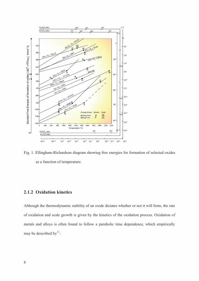
A useful presentation of standard free energies for the formation of selected oxides is an
Ellingham-Richardson diagram as shown in Fig. 1 10. By using this diagram stabilities of
oxides can be compared and the values of dissociation pressures can be obtained directly.
This information can be used to identify which element of an alloy that will form the most
stable oxide and is thereby likely to act as a protective corrosion resistant oxide layer on the
base alloy.
Page 18
8
Fig. 1. Ellingham-Richardson diagram showing free energies for formation of selected oxides
as a function of temperature.
2.1.2 Oxidation kinetics
Although the thermodynamic stability of an oxide dictates whether or not it will form, the rate
of oxidation and scale growth is given by the kinetics of the oxidation process. Oxidation of
metals and alloys is often found to follow a parabolic time dependence, which empirically
may be described by11:
Page 19
9
xk
dtdx
tp1' , Eq. 6
Integration over time yields:
0,0,2 CC'2 tptp kkx Eq. 7
where x is the oxide scale thickness, tpk , denotes the parabolic rate constant and 0C is an
integration constant. The parabolic law (Eq. 6) describes an oxidation process governed by
the lattice diffusion of the reactant through the oxide scale. Due to the continuously increasing
thickness with time, the diffusion paths of the migrating species increases, and the reaction
rate decreases.
Oxidation rates typically show Arrhenius-type temperature dependencies at constant oxygen
partial pressures, and can be expressed by:
TEa
kk R-
0e Eq. 8
Rate constants determined at various temperatures thus enables determination of the
activation energy for oxide growth, aE , by plotting values for parabolic rate constants as a
function of inverse temperature 7. A constant activation energy may imply that the same
oxidation mechanism predominates the oxidation process throughout the experimental
temperature interval. An overall temperature dependence deviating from the Arrhenius
behavior may similarly indicate a changeover between two limiting processes within a certain
temperature interval, for instance from inward oxygen diffusion to outward transport of
cations 12.
Page 20
10
Wagner theory
The first fundamental theory for describing oxidation kinetics was developed by Carl Wagner,
and published ten years after the empirically described parabolic law 13. Wagner based his
theory on the assumption that lattice diffusion of electrically charged species is rate limiting
for the oxidation process 8. Accordingly, the oxide formed must be dense, continuous and
perfectly adherent. Although the scale shows only small deviations from stoichiometry
defects in the oxide allow for migration. At both the metal – oxide and oxide – gas interface
reactions are assumed to be rapid, and local equilibria are established. Both ions and electrical
species are assumed to migrate independently, and the net electrical current is defined as zero.
Wagner’s original equation for metal oxidation is written:
O
a
aO
MMp a
ZZ
Dk O
O
ln d//
/ Eq. 9
where MD is the self-diffusion coefficient of the metal, /Oa and //
Oa represents the oxygen
activities at the metal – oxide and oxide – gas interface, respectively. This expression that can
be modified to describe a number of oxidation situations, e.g. the oxidation of a metal
deficient oxide, baOM , dominated by metal vacancies can be written:
//2
/2
2
p
p O/
, ln O
O
vtp pd
bD
k M Eq. 10
where /, tpk denotes the thickness related parabolic rate constant. In many studies of oxidation
kinetics weight gain due to oxygen uptake of a sample is measured, giving the weight related
parabolic constant, /, wpk . These two parabolic growth rates are related via the molecular mass
of oxygen, OM , the oxide, baOMM , and its density,
baOMd :
Page 21
11
/,
2
/, tp
OMO
OMwp k
dMbM
kba
ba Eq. 11
As previously described, Wagner’s oxidation theory is based on several assumptions and is
only valid when oxidation occurs under ideal conditions. However, the model has proven to
be remarkably accurate and versatile for describing oxide scale growth kinetics of numerous
metals and alloys under real conditions.
2.1.3 Diffusion
Diffusion is described by Fick’s laws, where the first law is written:
xCDJ Eq. 12
It relates the flux of the diffusing species, J , with the diffusion coefficient, D , and the
concentration, C , as a function of position, x . Determination of the diffusion coefficient of
the migrating species is essential for the predictions of growth rates, Eq. 9. Fick’s first law
states that a fixed concentration gradient is required for measuring D . However, this is often
difficult to establish experimentally, hence it is generally more convenient to measure the
change in concentration of the diffusing species as a function of time, given by Fick’s second
law, which can be written:
2
2
xCD
tC Eq. 13
Most oxidation processes of metals are governed by the diffusion of metal and/or oxidant.
When the initial oxide scale is formed further growth is sustained by either outward transport
of metal, and/or inward transport of oxidant. Counter direction diffusion of cations and anions
Page 22
12
is commonly found in growing oxide scales, and the parabolic growth rate can be related to
the diffusion coefficients 14:
2
//2
/2
O0
, ln pdDDZZ
bC
kpO
pO OMO
Mtp Eq. 14
The diffusion coefficients of the cations, MD , and anions, OD , is thereby of great importance
for understanding the oxidation process of the metal. However, this phenomenological
relationship does not explain the mechanisms responsible for the diffusion.
The solution of Fick’s laws can be modified to represent the explicit experimental parameters
15. Diffusion coefficients can be determined by various experimental methods, however, the
most common procedure is by tracer diffusion experiments using isotopes (e.g. 54Cr and 18O)
or foreign atoms (e.g. Fe and Mn in Cr2O3). The distribution of the labeled species in the
oxide is measured by depth sensitive elemental characterization techniques such as secondary
ion mass spectrometry (SIMS) or electron probe micro-analysis (EPMA).
2.1.4 Internal oxidation
Many metals and alloys are susceptible to internal oxidation during high temperature
exposures 6,16. When an oxidant is dissolved in the metal substrate, internal precipitation may
occur provided that the internal concentration of the oxidant is sufficient. Internal formation
of precipitates is controlled by the volume diffusion of oxidant through the metal matrix, and
the penetration of precipitates continues towards the depth of which the concentration of
oxidant is too low for continued growth 8. The concentration of the reactive alloy component
is essential for determining whether internal oxidation will occur or not. Wagner proposed a
Page 23
13
theoretical model for determining the critical concentration of reactive element in the alloy,
)0(BN , at which transition from internal to external oxidation takes place 17:
21
)()0(
2 B
Os
O
OX
ABOB D
DNVVgN Eq. 15
BOg is the volume fraction of internal precipitate, is the stoichiometric factor, AV and OXV
are the molar volumes of parent metal and precipitate, respectively. Further, )(sON is the
surface concentration of oxidant, and OD and BD are the diffusion coefficients of oxidant
and reactive alloy component, respectively.
The growth rate tpk , is in this case based on the rate limiting diffusion of oxidant into the
metal and can be expressed by 16:
)0(
)(
,B
sOO
tp NNDk Eq. 16
where OD is the diffusion coefficient of oxidant, )(sON is the solubility of oxidant at the
surface and )0(BN is the mole fraction of the precipitate forming metal, for instance chromium.
is a constant describing the blocking effect of precipitates and is the stoichiometric factor
for the precipitating phase. The condition for validity of Eq. 16 is )0()(BB
sOO NDND .
The model is based on the assumptions that the solubility product, spK , of the oxidant and
precipitate forming metal is vanishingly small, and that the solubility of the two reacting
elements is close to zero within the precipitation zone. The remaining metal matrix between
the precipitates is depleted of precipitate forming metal, and the diffusion of oxidant is
assumed to occur through the metal bulk alone and not being affected by the presence of the
Page 24
14
precipitates. As a result of this, the area fraction of precipitate is uniform as a function of
depth along the diffusion direction, and zero at the front of the precipitation zone. However,
in the case of the formation of internal precipitates with low stability, e.g. Cr2N, spK will not
be infinitesimal, and thereby formation of precipitates will not necessarily occur whenever
oxidant is present within the metal. Since ON decreases as a function of depth, the minimum
chromium concentration for sustained precipitation increases. In addition, it has been reported
that the formation of internal precipitates provides paths for interfacial oxidant diffusion and
thereby accelerates the internal precipitation, further reducing the validity of the classical
diffusion predictions for modeling these situations 18. The lack of complete precipitation will
necessarily mean that the volume fraction of precipitates, vf , varies with depth. This type of
situation was analyzed by Ohriner and Morral, and can be adopted to the internal nitridation
of chromium bearing alloys, given by the formation of Cr2N precipitates 9,19,20. The reaction
stoichiometry of the precipitate gives the basis for the solubility product of oxidant and metal
in the matrix:
)(2)0( sNCrsp NNK Eq. 17
By assuming that the metal diffusion in the precipitates is insignificant, and that
3)(sNsp NK , the precipitate fraction, r ,can be expressed by:
tr
rxN
DKtr
Cr
Nsp23)0( 1
14 Eq. 18
where is the solubility parameter defined as:
Page 25
15
)0(2
1
)( /1 CrsN
sp NNK
Eq. 19
By utilizing the Boltzmann transformation Eq. 18 can be converted to a differential equation
by integration:
'
0)(
)0(
2
2
d dd
811 r
sNN
Cr rxrx
NtDN
r Eq. 20
This model has proved to describe distribution of internal nitride precipitates in chromium
bearing alloys 9,20.
2.1.5 Defect chemistry of Cr2O3
Imperfections and defects in the oxide scales enable diffusion. Different types of defects give
rise to different diffusion mechanisms. Lattice or point defects in the crystal structure of the
oxides are responsible for bulk diffusion. Transport of atoms through bulk may occur either
by a vacancy mechanism where an atom in a normal site jumps into a neighboring vacant
lattice site, or by an interstitial mechanism where the atom moves from one interstitial site to
a neighboring interstitial site. The latter process involves substantial distortion of the lattice
and is therefore only likely when the moving atom is smaller than the atoms occupying the
normal lattice sites. Knowledge about the defect structure of the oxide is essential to evaluate
the migrating elements dominating the oxidation process.
The majority of oxidation experiments in this work have been performed below 1000 °C, and
it is therefore most relevant to consider the defect structure of Cr2O3 below this temperature.
Cr2O3 is a p-type semi-conductor at temperatures below 1000 °C 7,21,22. At the very lowest
oxygen partial pressures, there is a changeover to n-type electronic conduction. The most
Page 26
16
likely intrinsic ionic majority defects are chromium vacancies, ///Crv and interstitials, iCr ,
and minority defects are likely oxygen interstitials, //iO and vacancies, Ov . Given that the
above mentioned defects dominate concentration-wise, Cr2O3 displays the total
electroneutrality:
np //i
///CrOi O2v3v2Cr3 Eq. 21
Oxygen dependency
As Cr2O3 in an oxidation experiment is subjected to low oxygen activity near the metal –
oxide interface and high oxygen activity at the oxide – gas interface, it is relevant to consider
the dominating defect equilibria in Cr2O3 under these limiting conditions. At low oxygen
activities, undoped Cr2O3 is dominated by Cr interstitials and electrons through:
(g) Oe6Cr2O3Cr2 223/
iOCr Eq. 22
and the electroneutrality (Eq. 21) reduces to nCr3 i . While at the higher oxygen
activities however, Cr vacancies and electron holes are likely to dominate:
O///Cr22
3 O36hv2(g) O Eq. 23
and Eq. 21 in this case reduces to pv3 ///Cr . As illustrated by Eq. 22 and 23, the
concentration of all defects in Eq. 21 will be dependent on the oxygen partial pressure, 2Op .
The 2Op dependency of the individual defect concentrations may be deduced from the two
abovementioned limiting defect situations, in addition to the situation iCrv///Cr , which
is likely to dominate in the mid-2Op region, and the equilibrium constants for formation of
the ionic defects .
Page 27
17
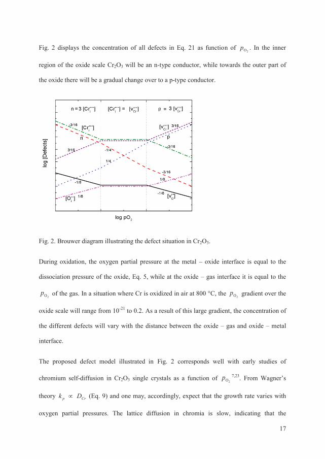
Fig. 2 displays the concentration of all defects in Eq. 21 as function of 2Op . In the inner
region of the oxide scale Cr2O3 will be an n-type conductor, while towards the outer part of
the oxide there will be a gradual change over to a p-type conductor.
Fig. 2. Brouwer diagram illustrating the defect situation in Cr2O3.
During oxidation, the oxygen partial pressure at the metal – oxide interface is equal to the
dissociation pressure of the oxide, Eq. 5, while at the oxide – gas interface it is equal to the
2Op of the gas. In a situation where Cr is oxidized in air at 800 °C, the 2Op gradient over the
oxide scale will range from 10-21 to 0.2. As a result of this large gradient, the concentration of
the different defects will vary with the distance between the oxide – gas and oxide – metal
interface.
The proposed defect model illustrated in Fig. 2 corresponds well with early studies of
chromium self-diffusion in Cr2O3 single crystals as a function of 2Op 7,23. From Wagner’s
theory Crp Dk (Eq. 9) and one may, accordingly, expect that the growth rate varies with
oxygen partial pressures. The lattice diffusion in chromia is slow, indicating that the
Page 28
18
concentration of defects is low in undoped Cr2O3 24. The correspondence between growth
rates and diffusion coefficients reported in literature may therefore have been fortuitous. The
relation between diffusion and oxidation rates will be further discussed later.
Dopants
Formation of pure Cr2O3 is unlikely to occur during high temperature oxidation of a Cr
containing alloy, and various constituents of the alloy may dissolve in the Cr2O3 scale. A
foreign cation may be treated as a dopant.
Mn is a possible lower valent dopant in Cr2O3, a common constituent in chromia forming
alloys. At high 2Op dissolution of Mn in Cr2O3 may proceed according to:
h2O3Mn2)g(O (s) MnO2 O/Cr22
1 Eq. 24
This situation indicates that a lower valent dopant will increase the hole concentration at high
oxygen partial pressures.
At low 2Op the dissolution of Mn may be written:
OO/Cr O2v2Ml (s) 2MlO Eq. 25
Higher valent dopants such as Ti, will on the other hand increase the concentration of
negative defects, notably electrons or Cr vacancies at low and high 2Op , respectively:
g)(Oe2O3Mh2)s(MhO2 221/
OCr2 Eq. 26
///CrOCr2 vO63Mh (s) MhO3 Eq. 27
Page 29
19
As the equilibrium concentrations of native defects in Cr2O3 are small, extrinsic impurities
play an important role in the defect structure Cr2O3. It has for instance been concluded that
the dominating p-type conductivity encountered at temperatures below 1000 °C is due to
compensation of extrinsic acceptor dopants by electron holes 21.
Effects of hydrogen and water
Hydrogen is expected to dissolve in chromia in the form of protons, or more precisely
substitutional hydroxide ions on oxygen ion sites. For a p-type conductor this reaction may
be written:
OO221 OH hO g)( H Eq. 28
or, in the presence of water vapor:
(g) OOH2h2O (g) OH 221
OO2 Eq. 29
Both these defect reactions express that introduction of protons in the oxide will decrease the
concentration of electron holes, and thereby also the p-type conductivity 21. Protons may also
in principle dissolve by formation of Cr vacancies according to:
///CrOO2 v2OH 63O (g) O3H Eq. 30
The total electro neutrality may be written:
nv3pCr3v2OH ///CriOO Eq. 33
It is expected that increasing concentration of Cr vacancies increases the cation diffusion
through the oxide, and thus also influences the oxidation rate of Cr2O3 forming alloys. As a
Page 30
20
significant proton concentration would increase the concentration of Cr vacancies, one may
suspect a similar effect of water vapor on the oxidation behavior of Cr containing alloys 25,26.
Formation of volatile chromium species
Cr2O3 is renowned for the evaporation of volatile chromium species at high 2Op 8,9,27. Under
dry oxidizing conditions, the formation of volatile CrO3 in metal deficient chromia can be
expressed by:
(g) CrOh3v (g) OCr 3///Cr22
3Cr Eq. 34
while under wet conditions another volatile species is more likely to be formed:
(g) OH)(CrOh3 v (g) OH (g) OCr 22///Cr222
3Cr Eq. 35
The loss of mass through evaporation promotes cation diffusion, resulting in an increased
degradation of the metal substrate. It has been found that the growth kinetics of chromia
forming alloys is increased by increasing OH2p and gas flow 28,29.
Oxidation of Cr
Although pure chromium is not used for practical applications on its own it is widely added as
an alloying element to improve corrosion properties of numerous alloys. The oxidation
behavior of Cr is therefore of great importance and has been investigated extensively for
several decades 6. By oxidation at high temperatures a scale of Cr2O3 is formed. The
protective nature of this scale is reflected by a parabolic growth behavior generally found by
oxidation above 700 °C at near atmospheric oxygen partial pressures, indicating diffusion
controlled oxidation mechanism 7. Reported parabolic rates differs up to 4 orders of
Page 31
21
magnitude, depending on the reaction conditions, sample preparation, surface finish,
microstructure of the metal interior, and the formation of volatile chromium species 30,31,32.
The oxidation rate of Cr is dependent on the oxygen pressure of the gas, indicating that the
formed scales behave as p- or n-type conductors and that the defect structure influences the
growth rates 33,34. However, the effect of the oxygen pressure may also be a result of
variations in the oxide scale microstructure. At reduced oxygen pressures, large stresses and
strains are developed within the oxide leading to deformation and cracking of the scale while
at high pressures the scales are more adherent and smooth 7,35-37. The adherence and protective
properties of Cr2O3 scales have also been found to be influenced by the presence of hydrogen
in the metal substrate 38,39. Furthermore, the adhesion and growth rate of chromia is increased
by introducing water vapor to the oxidizing gas 31,40,41.
Although a single phase oxide scale of Cr2O3 is formed by oxidation of Cr, it is often found
that such scales comprise several layers with different microstructure. This has been attributed
to a dissociation process resulting from the failure of the oxide scale to continuously
compensate the Cr consumption zone by plastic flow 42. The oxide scale will crack, and a
more porous oxide will form at the metal – oxide interface or within the oxide scale.
However, the outward cation diffusion through the inner layer of the scale is still the rate
limiting mechanism of the oxidation process.
By oxidation in oxygen rich atmospheres the evaporation of volatile chromium species can be
significant 27,43. Increased velocity of the gas flow, oxygen pressure and water vapor in the
oxidizing gas is found to enhance the evaporation rate 31.
Page 32
22
Oxidation of Fe-Cr alloys
In the initial transient stage of alloy oxidation all available elements, including Cr and Fe,
will react with oxygen and form oxides 7,44. The oxidation process is in this stage governed by
the oxide – gas interaction processes, usually following linear kinetics. Eventually, the scale
grows in thickness and diffusion of reacting species through the oxide scale becomes the rate
limiting represented by parabolic kinetics. The purpose of alloying with Cr is to form a
protective Cr2O3 scale that limits further oxidation and degradation of the alloy. The process
where the oxidation of a solute or alloying element is preferred and forms a continuous scale
on the surface of the alloy is referred to as selective oxidation. A protective oxide scale
formed by selective oxidation is recognized by the oxidation of the least noble constituent of
the alloy showing high stability of the oxide phase.
Chromia scales grown on Cr and Fe-Cr alloys show microstructural similarities, indicating
that the same oxidation mechanisms predominate the process 7. The variations in oxidation
rates reported for chromia forming Fe-Cr alloys are smaller (about two orders of magnitude)
compared to oxidation kinetics of pure Cr 31. The rate constants are generally found to
decrease with increasing Cr content in the alloy 45. At low Cr contents both Cr2O3 and iron
oxides, e.g. FeO, form on the sample surface and to some extent react into iron chromium
spinels, such as FeCr2O4 8. By increasing the Cr concentration a protective Cr2O3 scale is
formed. However, sustained growth can only be achieved as long as a critical level of Cr
content (> ~17 wt.%) is exceeded in the alloy. Most high temperature engineering Fe-Cr
alloys are therefore added excess Cr, i.e. 20 – 27 wt. %, to ensure formation of continuous
layers of chromia 46. Even at high levels of Cr in the alloy, Fe will dissolve into the oxide
scale and diffuse towards the oxide – gas interface. The result is an outer layer of (Cr, Fe)3O4-
spinels or iron oxides 8. As for pure chromium, the surface of the oxide scales is often
Page 33
23
convoluted and wrinkled, in contrast to the “grotesque shapes” formed on pure iron 11.
Features found on the surface such as interfacial cavities and pores often promote cracking
and spallation leaving local areas of the metal substrate open, resulting in an enhanced
oxidation 7,8. The formation of volatile chromium species, e.g. CrO3 (g) or CrO2(OH)2 (g), is
also found to increase the oxidation rate by evaporation of the oxide surface 27,28.
Water vapor in the oxidizing gas is generally found to increase the oxidation rate of Fe-Cr
alloys, compared to dry conditions 47. For many alloys initial formation and growth of a
protective chromia scale is followed by a significant increase in growth rate. The exact
mechanisms responsible for the enhanced rates are not fully understood, although several
theories have been suggested. Fujii and Meussner proposed that dissociative transport of
oxygen by water in interfacial voids maintained high rates of oxidation of Fe-Cr alloys (Cr
15 wt.%) in water vapor at 700 – 1100 °C 45,48. A similar mechanism was suggested by
Rahmel and Tobolski, proposing that oxygen transport within interfacial pores is facilitated
by a so called H2/H2O bridge 49. Water inside the pores oxidizes the metal at the alloy – oxide
interface, while hydrogen reduces the oxide on the outer surface of the void and forms water
again. Water vapor has also been suggested to accelerate internal oxidation of Fe-Cr alloys by
increasing the solubility of oxygen in the alloy through dissolution of hydrogen in alloys 50,51.
Hydrogen is commonly found in alloys as a result of the fabrication process. The presence of
hydrogen in the metal or oxide influences the oxidation behavior, and may alter
microstructure, adherence and/or composition of the forming oxide scales 52-55. As described
in an earlier section, hydrogen defects in the oxide scale have been proposed as an
explanation for the enhanced oxidation in water containing atmospheres 24-26. Formation of
protonic defects may be compensated by increased concentration of cation vacancies,
Page 34
24
accelerating the metal diffusivity. The overall result may be increased growth rate and
alterations in the oxide scale composition 53.
Presence of water vapor in the oxidizing gas also significantly increases the evaporation rate
from chromia forming alloys 27,28. By continuously removing chromium from the outer oxide
layer by evaporation, the ability to maintain the protective properties of the scale depends on
the evaporation rate and the outward flux of chromium from the alloy. The evaporation rate is
found to be proportional to the flow rate and water vapor content of the gas. Although the
oxidation of the alloy is increased, the mass loss through evaporation may lead to an effective
decrease in weight gain and oxide scale thickness of the metal during oxidation, following
para-linear kinetics.
If after a certain time the concentration of Cr in the alloy reaches a critical level (< ~17 wt. %)
the alloy can no longer re-form a protective scale. Failure of the protective chromia scale may
be recognized by the formation of iron oxides, internal oxidation and accelerated oxidation
rates 50,56. This process is termed breakaway oxidation and is detrimental for the performance
of the alloy. Water vapor in the oxidizing atmosphere has been observed to trigger breakaway
oxidation 28,56-58. It has been suggested that the H2O (g)/O2 (g) ratio at the metal – oxide
interface is essential for whether breakaway oxidation will occur or not. High levels of H2O
(g), increases the likelihood for triggering breakaway oxidation by increasing the solubility
and/or the diffusivity of oxygen in the alloy and thus promoting internal oxidation. Moreover,
at sufficiently high 2Op the formation of non-protective Fe rich oxide scales are favored.
To further improve the properties of alloys, minor alloying elements are added. Minor
additions (typically 0.2 – 5 wt. %) of selected elements (e.g. Al, Mn, Si, Ti) can result in
improved oxidation resistance, scale adherence, and/or increased outer spinel formation
7,9,46,59,60. So called reactive elements (e.g. Y, La, Ce, Zr) are also reported to have beneficial
Page 35
25
effects when added in small amounts (typically 0.1 – 0.2 wt. %) 61-63. Some of the effects of
reactive element additions are; increased selective oxidation of chromium, reduced oxidation
rate, increased scale adherence, modifications to the oxide microstructure and the growth
processes 61,64,65. The mechanisms responsible for these effects are not fully understood,
although numerous suggestions have been published 64.
Diffusion in oxide scales
Numerous studies have been dedicated to investigate and characterize the diffusion in single
and poly crystalline samples of Cr2O3, and in thermally grown chromia scales. In an early
study of Hagel and Seybolt the self-diffusion of Cr was determined by tracer experiments
from 1045 – 1550 °C. Based on the results it was suggested that the rate limiting step of high
temperature oxidation of Cr was the volume diffusion of Cr through Cr2O3 66. This was also
the conclusion of Kofstad and Lillerud after comparing the rate of formation of Cr2O3,
between 800 °C – 1100 °C, with existing data for chromium lattice diffusion 22,66,67. However,
the diffusion coefficients determined in these early studies did not only describe lattice
diffusion, but included also contributions from grain boundary diffusion and diffusion through
other high diffusivity paths such as pores and micro cracks. This was illustrated in later
studies concluding that the chromium lattice diffusion was 4 – 7 orders of magnitude lower
than previously determined (1100 – 1570 °C), and that chromium grain boundary diffusion
would be the predominating transport mechanism 23,68-71. A dominating outward cation
diffusion should lead to predominant oxide growth at the outer oxide – gas interface,
however, a significant fraction of growth has been found to take place at the oxide – metal
interface, suggesting that inward diffusion of oxygen also makes a substantial contribution to
the oxidation process 38,52,72,73. In order to clarify the inconsistencies in literature Sabioni et al.
Page 36
26
performed a comprehensive study of chromium and oxygen diffusion in single and poly
crystalline Cr2O3 70,74-76. They reported that both bulk and grain boundary diffusion of oxygen
were faster than the chromium diffusion under the same conditions (1100 – 1300 °C).
However, the deviation between oxide growth rates and diffusion coefficients remained
unexplained. Tsai et al. compared the cation and anion diffusion in massive single and
polycrystalline Cr2O3 samples with thermally grown oxide scales of the same composition at
lower temperatures (800 - 900 °C) 77-79. Their results showed that the bulk diffusion
coefficients of chromium and oxygen were comparable for all three different forms of Cr2O3
samples. Interestingly, grain boundary diffusion of both elements was higher in thermally
grown scales than in synthesized polycrystals. Further, it was established that chromium
diffusivities (especially in grain boundaries) were faster than oxygen. This was in agreement
with results from other studies of tracer diffusion 80,81. By proposing some modifications to
the more classical approach of analyzing diffusion profiles by taking the surface roughness
into account, Tsai et al. found reasonable agreement between calculated (based on diffusion
coefficients) and experimentally obtained growth rates of Cr2O3 scales. It was concluded that
counter current diffusion of chromium and oxygen diffusion, mainly via grain boundaries,
maintain growth of chromia scales 78,80,82.
Lobnig et al. investigated the diffusion of Cr, Mn, Fe and Ni at 900 °C in thermally grown
Cr2O3. They found that the lattice diffusion of Mn was about two orders of magnitude higher
than for the other cations, and that the diffusion decreased in the order DMn > DFe > DNi >
DCr, as also predicted by others 83,84. This was used to explain the frequently observed
formation of an outer (Cr,Mn)3O4-spinel during oxidation of Mn bearing high-alloy steels,
such as ferritic interconnect materials 85,86. Sabioni et al. on the other hand did not find any
significant variations in bulk or grain boundary diffusion when comparing Mn and Cr (700 –
1100 °C) 87. They suggested that MnO and Cr2O3 form simultaneously during the initial stage
Page 37
27
of oxidation. Due to the minor amounts of Mn in the steel and the high stability of chromia
further growth is expected to be dominated by formation of Cr2O3. The growth of the outer
(Cr,Mn)3O4-spinel layer was then attributed to the diffusion of Mn at similar rates as Cr
through the inner Cr2O3. Moreover, Gilewicz-Wolter et al. found that Mn was the fastest
diffusing cation, compared to Cr and Fe, through MnCr2O4 (800 – 900 °C), resulting in
further accumulation of Mn in the outer region of the spinel phase 88.
The formation of multilayered oxide scales on commercial alloys such as interconnects also
influences the oxygen transport. Horita et al. reported that the oxygen diffusion in thermally
grown oxides on complex SOFC interconnect alloys is faster than in Cr2O3 and about two
orders of magnitude higher than the growth rates of the oxide scale 89,90. This discrepancy
between growth rates and diffusion coefficients remains unaccounted for although several
explanations have been proposed.
Thermal nitridation of chromium bearing alloys
Many metals and alloys are susceptible to corrosion by nitridation during high temperature
exposure in nitrogen containing atmospheres. During nitridation both internal and external
metal nitride phases are possible, e.g. Cr2N or CrN 9. Nitridation is a widely used technique
for hardening of steels, and to improve wear and corrosion resistance 46,91. Surface coatings of
CrNx or thermal exposures in nitrogen containing atmospheres can be used to obtain a thin
protective layer 92. Although the chromium nitrides are found to rapidly form into Cr2O3 at
high temperatures in oxygen containing atmospheres, the high temperature oxidation rate of
steels has been found to be reduced by thermal nitridation treatment 93,94. The formation of
dense electrical conducting and corrosion resistant nitrides has also been found to provide a
Page 38
28
beneficial effect on the electrical resistance of interconnect materials in fuel cells 95-99.
However, under certain conditions the amount of nitrogen absorbed into the alloy may exceed
the solubility limit, resulting in the formation of internal nitride precipitates 46. This can lead
to embrittlement of the alloy. Many industrial processes involve atmospheres containing
nitrogen or ammonia, and knowledge of nitridation processes of alloys is therefore of key
interest for avoiding premature failure of the metallic equipment. Young et al. have
investigated the thermal nitridation of various iron and nickel based alloys 18,20,100,101. They
show that the internal nitridation of alloys cannot be described by the Wagner diffusion model
of internal oxidation, assuming infinitesimal solubility products and complete reaction
between chromium and nitrogen. Due to the low stability of chromium nitrides, the volume
fraction of internal nitride precipitates decreases along the diffusion depth of nitrogen into the
alloy, and the distribution of precipitates is controlled by the diffusion path of nitrogen, and
not nucleation. This means that other theories e.g. as proposed by Ohriner and Morral, must
be utilized in order to predict the amount of chromium in the alloy required to form external
scales rather than internal precipitates 19.
Page 39
29
3 Interconnect materials for high
temperature solid oxide fuel cells
Purpose and properties
The theoretical output voltage of a fuel cell is given by the electrochemical potential
difference between the reacting fuel and oxidant (e.g. H2 and O2) and the product of these
(e.g. H2O). To reach usable voltages, multiple cells are connected in series using
interconnects. Interconnects must provide high electrical conductivity while separating the
fuel and air and acting as one of the main structural components in the fuel cell assembly.
This means that the material used for interconnect must fulfill certain requirements:
- High electrical conductivity at high temperatures
- High chemical and mechanical stability
- Suitable thermal expansion with other fuel cell components
- Gas tightness
- Easy machining and fabrication
- Low cost
Page 40
30
While the four first properties may be in focus during the early stages of fuel cell research, the
two latter points will play increasingly important roles towards commercialization.
Materials
Many materials have been proposed as possible interconnects for high temperature fuel cells.
Ceramic and metallic materials represent the two main potential materials families and have
been investigated for decades. A short literature survey of the most essential materials in
interconnect research is given in the following.
3.1.1 Ceramic interconnect materials
For several decades the operating temperature of SOFCs was above 1000 °C. At such high
temperatures metallic materials are inapplicable for several reasons. This led to the
consideration of various ceramic candidate materials for interconnecting purposes. The most
widely investigated ceramics were perovskites, holding high electronic and low ionic
conductivity. Only a few candidates could meet the severe demands, and among these
lanthanum chromites received the most attention. Pure LaCrO3 does not hold sufficiently high
electronic conductivity, hence various dopants were utilized. Under oxidizing conditions
acceptor doping the material by using e.g. Ca and Sr will increase the p-type conductivity
102,103. Although high electrical conductivities were achieved by utilizing various dopants and
by mixing oxide phases e.g. Ca doped LaCrO3 and Sm doped CeO2, some challenges
remained unsolved for the ceramic interconnects. The brittle nature, complicated fabrication
and high cost are some of the main reasons why these materials are in most cases discarded.
Page 41
31
3.1.2 Metallic interconnect materials
Through the decades of extensive research on new and improved materials, and the
introduction of anode supported SOFCs the proposed temperature region for SOFC operation
has been reduced to ~800 °C. In the case of PCFCs the target working temperature is usually
~650 °C. The lowered operating temperatures enable the use of less complex and costly
materials for the interconnect, and various metals and alloys have gained attention as
interesting candidates. Some of the first proposed interconnect materials were unalloyed noble
metals such as gold, platinum and silver. The latter was regarded as the most probable
candidate mostly due to cost, high electrical and thermal conductivity. However, due to the
combination of low melting point, and too large TEC silver was discarded 104. Heat resistant
commercial alloys for engineering purposes, e.g. Fe-Cr-Al, Ni-Cr-Al, and Co-Cr-Al, could be
considered based on their superior oxidation resistance 46. At high temperature exposures in
oxidizing environments these alloys rely on the formation of a protective Al2O3 scale.
Although, this scale provides excellent protection against corrosion, these alloys are ruled out
because of the electrically insulating properties of the oxide 105. Similar arguments can be
used against silica forming alloys. Chromia formers are more susceptible to high temperature
corrosion and the oxidation resistance is lower than for alumina and silica formers, however,
the electrical conductivity of chromia is orders of magnitude higher than that of alumina and
silica 106. Therefore, two of the most widely used types of alloys for engineering purposes,
nickel and iron based chromium bearing alloys came up early in the process, and are still of
the most promising metallic interconnect materials 104,107,108.
Extensive research has been invested in nickel based chromium bearing alloys for
interconnect purposes 108,109. These alloys, e.g. Haynes 230 and Haynes 242, can offer
relatively high electrical conductivity of the oxide scale combined with slow oxidation
Page 42
32
kinetics 110-112. Despite tailoring of the alloy composition to try to meet the interconnect
requirements, the thermal expansion of nickel based alloys (15 - 20×10-6 /°C) are in general
considerably higher than the other fuel cell materials. This makes it nearly impossible to
match the other components of the fuel cell, and excludes these materials as interconnect
candidates.
Ferritic stainless steels have been considered from the beginning of the search for metallic
interconnect materials 104,113. The low cost and suitable TEC coupled with reasonably good
oxidation resistance made this family of alloys tempting alternatives to ceramics and nickel
based alloys. During long term exposures the alloy may be depleted of Cr, and the exclusive
formation of protective chromia may not be sustained. The amount of chromium in the alloy
also influences its thermal expansion coefficient, and can therefore be controlled to match the
other fuel cell components 115,116. As a result of these arguments most ferritic candidate
interconnect materials contain 17 – 26 wt.% Cr. Further improvements of the scale adherence
and oxidation resistance can be achieved by additions of reactive elements, e.g. Y and La,
either in metallic form or as oxides (oxide dispersion strengthening, ODS) 61,104,107,117. Several
other elements can also be utilized to tailor the metallurgical properties and the oxidation
processes of the alloy 117.
Chromia formers have the disadvantage that volatile chromium species form during oxidation
27,118. In addition to the increased oxidation rate, oxide and/or oxyhydroxide species of
chromium released as gas from the interconnect can migrate into the cathode and react into
various chromium containing phases, e.g. strontium chromites 119-121. These phases typically
decrease the electrical conductivity of the cathode material, as well as reduce the number of
active catalytic sites, resulting in a degradation of the cathode’s performance 122. In order to
limit the evaporation, Mn is frequently added in small amounts to the alloy matrix (0.2 – 0.4
Page 43
33
wt %). This enables the formation of (Cr,Mn)3O4-spinel phases in the outer part of the oxide
scale 123. Chromium manganese spinels hold higher electrical conductivities than Cr2O3 and
improve the total electrical conductivity of the oxide scale.
As a result of the extensive research a ferritic stainless steel was developed specifically for
SOFC interconnect application, Crofer 22 APU (ThyssenKrupp VDM) 124. This is still one of
the most widely used interconnect alloys for SOFC. The TEC (~12×10-6 /°C) matches that of
other fuel cell components. The alloy contains ~22 wt.% Cr to form a protective chromia
scale during long term operation, yielding relatively high oxidation resistance 114,125. Small
additions of La improve the oxidation resistance. Further, minor amounts of Mn and Ti are
added to form an outer spinel layer, both to reduce the evaporation and to enhance the
electrical conductivity of the oxide scale. Titanium additions are also expected to reduce the
wrinkling of the oxide. However, some concern has been raised about the high temperature
mechanical strength of the alloy. This issue was addressed by the development of the Crofer
22 H, where Nb, W and Si was added to achieve higher creep strength and improved
oxidation resistance 126-128. A similar approach was used by Sandvik Materials Technology
when developing the Sanergy HT 129. This ferritic steel contains similar amounts of Cr and
Mn as the two Crofer alloys, resulting in an oxidation behavior recognized by an outer
(Cr,Mn)3O4-spinel layer over a sub layer of Cr2O3. Minor amounts of Nb and Mo were added
to improve the high temperature strength and oxidation resistance. Nb is often found as
precipitations inside the alloy after high temperature exposures forming so called Laves
phases. These precipitates have the effect of trapping Si, which will limit the formation of
silica and thereby improve the total electrical conductivity 130,131.
The air on the cathode side of a SOFC or PCFC will contain water vapor in various amounts.
Water vapor is known to influence the oxidation behavior of chromia formers. It is generally
Page 44
34
found that the oxidation rate increases by introducing water vapor 7,132,133. Changes in
microstructure and composition of the oxide scales have also been reported, represented by
increased formation of Fe-rich oxides, and internal oxidation 7,28,50,51,134. Presence of water
vapor can also improve scale adherence 123. An increased Fe concentration in the oxide may
have a beneficial effect on the electrical conductivity of the scale 135-137. Evaporation of
chromium species is generally found to increase by increasing water vapor content in the
oxidizing gas 28,119. Mass loss through evaporation can make it difficult to quantitatively
determine the effect of water vapor on the oxidation rate 138.
Effects of dual atmosphere environments
The interconnect will be simultaneously exposed to oxidizing conditions (air) on the cathode
side and hydrogen containing atmospheres (fuel) on the anode side, the oxygen partial
pressures are high enough to form oxides, i.e. Cr2O3 and (Cr,Mn)3O4-spinels, in both
environments. Investigations of ferritic stainless steels have revealed similar oxidation rates
for air and simulated fuel environments 139,140. Although the same oxide phases are formed in
fuel as in air, the microstructure of the oxide scales are changed. The octahedral shaped spinel
grains observed in air is replaced by fibrous shaped particles also called whiskers 141.
The permittivity of hydrogen in steel at high temperatures is high and expected to rapidly
saturate the alloy 142. High diffusivity paths, such as grain boundaries in the alloy interior
have been suggested to further enhance hydrogen permeation depending on the alloy
composition 54,130. The transport of hydrogen through chromia is slow, hence, when a
continuous oxide scale is formed on the anode side of the alloy, further supply of hydrogen
during the thermal treatment is limited by the hydrogen permeability of the scales 24,38,143,144.
Page 45
35
In so called dual atmosphere environments simulating fuel cell conditions (fuel on the anode
side and air on the cathode side) it has been shown that the composition and growth of oxide
scales in air when hydrogen is present on the other side of the sample are significantly
different from the scales formed in air on both sides 53,54,145-147. Scales formed in air under
dual atmosphere conditions are reported to hold higher concentrations of Fe compared scales
formed in air only 145-148. Moreover, Yang et al. found that by introducing water vapor to the
air on the cathode side under dual atmosphere conditions, the Fe content in the oxide scales of
ferritic stainless steels was further increased 145.
The changes in oxidation behavior under dual atmosphere conditions have been attributed to
formation of protonic defects by dissolution of hydrogen in the oxides formed in air 149,150.
Protons may be charge compensated by cation vacancies, leading to an increase in the
vacancy concentration and enhanced outward transport of metal ions 26,149,151.
It has also been suggested that the presence of hydrogen may locally depress the 2Op favoring
the formation of isolated Fe-rich nodules 54. One should also be aware that hydrogen may
form steam within the oxide scales. If a sufficiently high steam pressure is built up pores may
form which may increase the inward oxygen transport and induce faster scale growth 147,152.
This could also result in localized metal attack as observed in association with the Fe-rich
nodules.
Furthermore, the extensive growth of iron rich oxides may indicate that dual atmosphere
environments increase the risk of breakaway oxidation. The possibility for breakaway
oxidation to occur is reported to increase by an increasing water vapor content in the
oxidizing gas, and that a high H2O (g)/O2 (g) ratio is more likely to trigger breakaway
oxidation than a low ratio 50,51,56,153,154. Breakaway oxidation can in such case be identified by
the formation of Fe rich nodules, localized metal loss and internal oxidation.
Page 46
36
Coatings
Although strongly influenced by the alloy composition, scale formation is inevitable and the
oxide phases formed may not hold sufficiently high electrical conductivity. Further, the
evaporation of volatile chromium species resulting in cathode poisoning remains as one of the
critical issues for the application of stainless steels as interconnects 122. It is therefore a broad
consensus that coatings are needed in practical applications of stainless steel interconnects.
The idea of applying coatings to improve the performance of alloys is not exclusive for the
SOFC interconnect research, also in many other applications coatings are used, mostly with
the aim of reducing the oxidation rate. However, in the case of interconnect materials other
requirements are equally important, including to improve the electrical conductivity and limit
chromium evaporation. Although an additional fabrication step is introduced in the
manufacturing process the total cost of the interconnect may not be severely increased since
less expensive and complex alloys may be utilized provided the coating is protecting the alloy
from extensive oxidation.
Various perovskite and spinel oxide coatings have been investigated in the recent years 140,155-
168. Among a wide variety of oxide coatings, Co containing spinels (e.g. (Co,Mn)3O4 and
Co3O4) have proved to be effective in reducing chromium evaporation, while also providing
high electronic conductivity 169. However, in order to obtain effective blocking of volatile
chromium species most of these oxide coatings have been rather thick. This can often result in
challenges when it comes to adherence, mechanical stability and sufficiently high electrical
conductivity.
Application of thin layers of metallic Co and/or Ce can substantially reduce the corrosion
rates and thus increase the lifetime of the fuel cell stack 170. Furthermore, metallic coatings
simplify the manufacturing process as no sintering or annealing is required as for the ceramic
Page 47
37
coatings. By oxidation, the Co containing coatings form outer layers of (Co,Mn)3O4 and
Co3O4 that are reported to be effective barriers to evaporation and good electrical conductors
168,171. Metallic coatings are thereby considered as promising candidates for improving the
high temperature properties of ferritic interconnect materials.
Page 49
39
4 Experimental
This chapter includes materials selection and some of the most important characterization
methods. Brief descriptions of the experimental setups and instrumentations used during the
work of this thesis are given with the aim of identifying the most important equipment.
Materials selection
The expected low operation temperature of PCFCs enables use of relatively inexpensive
interconnect materials such as stainless steels. In this thesis we have been focusing on a newly
developed alloy from Sandvik Materials Technology, Sanergy HT. This alloy has been
specifically developed as a interconnect material, and tailored to meet the requirements of
high temperature fuel cells, i.e. SOFC and PCFC.
In addition, another interconnect material, Crofer 22 APU (ThyssenKrupp VDM) was used
during nitridation experiments, together with ten model alloys. The compositions of all alloys
are listed in Table 1.
Page 50
40
Table 1. Chemical composition, wt. %, of alloys used in this study 128,129.
Thin layers of metallic Co and Ce had been applied by a roll-to-roll process during the
fabrication. For the coated samples investigated in this study, a single layer of 800 nm Co or
a double layer consisting of 10 nm Ce with 800 nm of Co on top were applied.
Experimental setup and instrumentation
4.1.1 Dual atmosphere setup
The sample holder used for dual atmosphere exposures was made from two stainless steel
flanges connected to a gas mixer with two separate outlets enabling flow of different gases in
each of the individual gas compartments. Samples were mounted in the setup and sealed
Alloy Fe Ni Cr Mn Mo Nb Add.
Sanergy HT Bal. - 22 0.5 1.0 0.75 Ti
Crofer 22 APU Bal. - 22 0.5 - - La, Ti
Fe-10Cr 90 - 10 - - - -
Fe-25Cr 75 - 25 - - - -
Fe-35Cr 65 - 35 - - - -
Fe-50Cr 50 - 50 - - - -
Fe-27Ni-10Cr 63 27 10 - - - -
Fe-22Ni-25Cr 53 22 25 - - - -
Ni-10Cr - 90 10 - - - -
Ni-25Cr - 75 25 - - - -
Ni-35Cr - 65 35 - - - -
Ni-50Cr - 50 50 - - - -
Page 51
41
mechanically using copper gaskets and bolts, Fig. 3. A high flow of Ar was continuously
flushing outside of the experimental setup to decrease degradation of the setup and to avoid
any effects of eventual leakages from the reactive gases. Leakages were tested for by pumping
vacuum in the two chambers both before and after the oxidation experiments using a rotary
pump. Fuel cell conditions were simulated by introducing either wet or dry air on one side
(cathode) and 5% H2 + Ar (wet or dry) on the other side (anode). Serving as a reference, one
sample was additionally inserted into each of the two gas compartments and thereby exposed
to the same thermal treatment in single atmosphere environments.
Fig. 3. Schematic illustration of experimental setup for dual atmosphere exposures.
4.1.2 Electrical measurements
Electrical resistance measurements were carried out in a ProboStat measurement cell (NorECs
AS). Before each experiment two samples were pre-oxidized in wet air for 24 h at 700 °C,
and two gold wires were spot welded on each of the samples. The spot welded electrodes
ensure good electrical contact with the samples, eliminating the contact resistance between
sample and electrode. Further, Pt ink was painted on one side of each sample before they were
Page 52
42
sandwiched together with Pt grid connecting the painted surfaces. The sample assembly was
then mounted in the measurement cell. An S-type thermocouple placed next to the samples
was connected to a Eurotherm 2216 temperature controller that was used to control the
furnace temperature. A constant current was applied and the resulting voltage drop over the
interface between the two samples was measured using an Agilent 35210 data acquisition unit
with a voltmeter switch module. Contributions to the resistance from the alloy itself and the
platinum contact layer were considered negligible. The setup was tested for several currents
and the resulting voltage behaved according to Ohm’s law indicating that the resistance
measured was purely ohmic.
4.1.3 Thermogravimetry
Thermogravimetry is one of most widely used methods in the field of oxidation and corrosion
science. The strength of the method is the in-situ measurement of the oxidation rate. The
specific instrument used for thermogravimetric measurements in this work was a C.I.
Electronics MK2 microbalance with a maximum sensitivity of 10 μg, and a maximum load
capacity of 5 g. Both sample and counterweight were suspended from the balance arms using
Pt threads. The sample was held in a closed alumina tube inside a vertical tube furnace, and
the counterweight was held at room temperature in a glass tube. The gas tight TG setup was
connected to a gas mixer controlling the composition and flow of the reaction gas. Due to
various sources of noise, the practical sensitivity at high temperatures when measuring in air
was ~0.8 mg corresponding to ~0.1 mg/cm2.
4.1.4 Gas phase analysis
Page 53
43
A gas phase analysis apparatus (GPA) was utilized for oxidizing samples in various isotopic
oxygen atmospheres. The GPA consists of an enclosed quartz tube used as reaction chamber
for the samples, a mass spectrometer and a gas supply system. The samples were inserted into
the quartz tube, and a moveable horizontal tube furnace was rolled into position for heating
the samples. Rapid heating/cooling was achieved by rolling the furnace back and forth while
at high temperatures. The total pressure in the enclosed volume, and the composition of the
gas was monitored using a Pfeiffer CMR 261 pressure gauge and a Pfeiffer Prisma QME 200
quadropole mass spectrometer (MS), respectively. The gas supply system enabled use of
atmospheres of different oxygen isotopes (18,18O2 and 16,16O2).
4.1.5 Gas mixer
For controlling the atmosphere during heat treatment of the samples, in-house built gas mixers
were used. Although slightly different design of the different gas mixers, the basic working
principles were the same. The gas flow is controlled by several rotameters (Brooks
Instruments Sho-Rate 1355). Bubblers filled with di-buthylphtalate are connected to the
flowmeters to create a small overpressure through the various parts of the gas mixer and
finally over the samples. A column containing P2O5 is used as a drying stage for the gas
giving a OH2p ~ 10-5 atm. Water vapor is introduced by passing the gas through a saturated
solution of KBr and water, resulting in a OH2p ~ 0.025 atm at 25 °C.
Materials characterization
4.1.6 Scanning electron microscope
Page 54
44
All micro structural characterizations of the samples in this work were carried out using a FEI
Quanta 200 F scanning electron microscope (SEM) equipped with a field emission gun
(FEG). The instrument is a so called environmental SEM (ESEM) that can operate at chamber
gas pressures between 10-4 Pa and 4000 Pa. This enables imaging of samples with low
electronic conductivity without further sample preparation, e.g. by applying conductive
coatings. The SEM was equipped with an Everhart-Thornley detector (ETD) for detecting
secondary electrons at high vacuum mode, and a large field detector (LFD) for low vacuum.
A solid-state backscatter detector, SSD-BSD, was used for phase contrast imaging by
backscattered electrons. The SEM was, moreover, equipped with an energy dispersive X-ray
spectrometer (EDS, EDAX Pegasus 2200). The EDS detects characteristic X-ray radiation,
and is used for semi quantitative elemental analysis of the samples.
Cross sections were also characterized by electron back scattered diffraction (EBSD, EDAX
OIM Analysis System with a CD-200 Nordiff camera). This technique was used for mapping
of crystallographic orientation.
4.1.7 Secondary ion mass spectrometer
Characterization of oxygen isotope distribution in oxide scales was carried out by secondary
ion mass spectrometer (SIMS) using a Cameca IMS 7f instrument with a primary beam of 15
keV Cs+ ions. Concentration profiles of 16O and 18O were recorded versus depth. The depth of
the sputtered craters was measured with a profilometer (Dektak 8 stylus). For depth
calibration a constant erosion rate was assumed. The rastering area was 200×200 μm, while
the area of detection was a centered 70×70 μm area.
4.1.8 X-ray diffraction
Page 55
45
In order to investigate the phases present on the heat treated metal samples X-ray diffraction
(XRD) was used. Three different instruments were utilized; for the samples treated at UiO a
Siemens D5000 was used as a routine instrument until it was replaced by a Bruker D8
Advance, while a Philips X’pert Pro was used to analyze the nitrided surfaces of samples
fabricated at UNSW.
4.1.9 Dilatometry
Thermal expansion measurements were carried out using a Netzsch DIL 402C dilatometer.
The instrument utilizes the displacement of a horizontal pushrod to determine the linear
dilation of the sample as a function of temperature. Measurements were carried out in dry
nitrogen atmosphere in order to limit the oxidation of alloy samples. The instrument has a
resolution of 0.125 nm at 500 μm measuring range, and the temperature accuracy for the S-
type thermocouple used is ±1 °C up to 1000 °C.
Page 57
47
5 Papers and manuscripts
PAPER I Sandvik Sanergy HT - A potential interconnect material for LaNbO4–based
proton ceramic fuel cells
Skilbred, A. W. B.; Haugsrud, R. J. Power Sources 2012, 206, 70.
PAPER II Investigations of oxidation mechanisms and oxygen diffusion in oxide scales
grown on coated and uncoated interconnect material for solid oxide fuel cells
Skilbred, A. W. B.; Haugsrud, R. To be submitted.
PAPER III The effect of dual atmosphere conditions on the corrosion of Sandvik Sanergy
HT
Skilbred, A. W. B.; Haugsrud, R. Int. J. Hydrogen Ener. 2012, 37, 8095.
PAPER IV The effect of water vapour on the corrosion of Sandvik Sanergy HT under dual
atmosphere conditions
Skilbred, A. W. B.; Haugsrud, R. Oxid. Met. Published online: 06 October
2012, DOI: 10.1007/s11085-012-9313-7
MANUSCRIPT A Thermal nitridation of iron and nickel based chromium holding
alloys
Skilbred, A. W. B.; Norby, T.; Zhang, J.; Young, D. J. To be submitted.
Page 59
49
PAPER I:
Sandvik Sanergy HT – A potential interconnect material for LaNbO4-based proton
ceramic fuel cells
Skilbred, A. W. B.; Haugsrud, R. J. Power Sources 2012, 206, 70.
Page 61
59
PAPER II:
Investigations of oxidation mechanisms and oxygen diffusion in oxide scales grown on
coated and uncoated interconnect material for solid oxide fuel cells
Skilbred, A.W. B; Haugsrud, R. To be submitted.
Page 63
83
PAPER III:
The effect of dual atmosphere conditions on the corrosion of Sandvik Sanergy HT
Skilbred, A. W. B.; Haugsrud, R. Int. J. Hydrogen Energ. 2012, 37, 8095.
Page 65
93
PAPER IV:
The effect of water vapour on the corrosion of Sandvik Sanergy HT under dual
atmosphere conditions
Skilbred, A. W. B.; Haugsrud, R. Oxid. Met. Published online: 06 October 2012, DOI:
10.1007/s11085-012-9313-7
Page 67
111
MANUSCRIPT A:
Thermal nitridation of iron and nickel based chromium bearing alloys
Skilbred, A. W. B.; Norby, T.; Zhang, J.; Young, D. J. To be submitted.
Page 69
145
6 Summarizing discussion
The papers presented have addressed various aspects regarding the high temperature
properties of interconnect materials for SOFC and PCFC. A relatively newly developed
ferritic stainless steel Sandvik Sanergy HT was, after careful materials selection, chosen as a
promising candidate. Since little information about the high temperature properties of the
Sanergy HT was found in literature, it was decided to investigate the material thoroughly,
focusing on its performance under PCFC conditions. In PAPER I an overview of key high
temperature properties of the material is given, revealing the overall features of the oxidation
process under various conditions. Further characterization of the oxidation is presented in
PAPER II, focusing on the diffusion of oxygen ions and cations to reveal the mechanisms
governing the oxidation process. PAPER III and IV address key aspects of the oxidation
behavior of Sanergy HT under simulated fuel cell dual atmosphere conditions. The effect of
dual atmosphere exposures was clear, recognized by the formation of Fe rich oxide nodules
accompanied by localized metal loss. It is suggested that the Sanergy HT may have to be
improved by coatings in order to meet the requirements of long term operation in a fuel cell.
PAPER III and IV presents some results on the oxidation behavior of Sanergy HT where a
double layered metallic coating of 10 nm Ce and 800 nm Co had been applied. Another
possible method for improving the oxidation resistance and mechanical properties of steels is
thermal nitridation. This was also suggested utilized in the case of interconnects for PCFC.
PAPER V presents a study performed to research the thermal nitridation of various steels,
including two commercial ferritic interconnect steels. It was found that the amount and depth
of internal Cr2N precipitates increased with increasing Cr content, attributed to formation of
high diffusivity paths for nitrogen along metal–nitride interfaces.
Page 70
146
The aim of this chapter is to take the discussions in PAPER I – IV further, and to link the
individual works.
Oxidation behavior of Sanergy HT
The oxidation of Sanergy HT at high temperatures in single air atmospheres follows parabolic
kinetics, indicating that the oxidation is governed by diffusion of reacting species through the
forming oxide scale. This is commonly found for chromia and alumina formers. It is assumed
that outward diffusion of cations is the rate limiting step during oxidation of these types of
alloys. However, by screening the literature on diffusion properties of Cr2O3 the domination
of growth in the favor of cation diffusion is not so obvious.
During the oxidation of Sanergy HT, and other Cr and Mn bearing alloys, the oxide scale
comprises an inner layer of Cr2O3 and an outer layer of (Cr,Mn)3O4 spinel. By two stage
oxidation we found that the predominant oxide growth occurs in the outer region near the
oxide – gas surface, which is a good indication that outward transport of cations is the
predominant process of the oxidation. However, in this study the two stage oxygen isotope
profiling by SIMS was performed on samples oxidized for a relatively short period of time,
and the outer spinel layer was thin compared to the chromia layer. Our results show that by
extending the oxidation time, and thereby also increasing both the total and relative thickness
of the outer spinel, the (18O and 16O) isotope distribution profiles were remarkably different
and indicated almost complete exchange in the outer oxide scale (close to equal
concentrations of the two isotopes). Close to the metal – oxide interface insignificant
exchange had occurred (meaning that one of the isotopes (16O) was only found in small
amounts).
Page 71
147
Both in the work presented in this thesis (PAPER II) and in literature, rather high oxygen
diffusion coefficients are found in thermally grown oxide scales compared to what is expected
based on studies of the oxidation mechanism. Rapid gas exchange and oxygen diffusion in the
spinel phase is also indicated by the slightly “S-shaped” diffusion profiles at higher
temperatures (900 °C). Based on the depth of the SIMS profiling we found that the obtained
diffusion profiles presented in PAPER II are mainly representing the oxygen ion diffusion in
the outer (Cr,Mn)3O4-spinel layer. Indicating that the effective oxygen diffusion through the
outer spinel phase may be higher than through the inner chromia layer, and that the transport
of oxygen may play a more pronounced role in the oxidation process than expected. This
means that a significant fraction of oxide growth occurs inside the oxide scale, close to the
interface between the spinel and chromia. And that the outward cation transport through the
inner Cr2O3 is the rate limiting mechanism. Mrowec et al. have proposed a similar
mechanisms to account for the formation of multiple layered single phase oxide scales
frequently found for e.g. chromia formers 42.
The effective oxygen diffusion measured also includes transport through high diffusivity
paths e.g. grain boundaries, and transport through micro cracks and pores, the measured
effective oxygen diffusion may therefore be substantially higher than the bulk diffusion
coefficient.
Based on the results from both oxidation studies (including isotopic two stage oxidation) and
the oxygen diffusion profiles we propose that the oxidation process can be separated into
several stages with respect to time, Fig. 5. The rate and duration of the separate stages depend
on the temperature and atmosphere. The figure also includes schematics illustrating SIMS
profiles resulting from the separate stages of oxidation. In the initial stage (stage 1), transient
oxidation occurs and a thin oxide scale is established where the composition reflects
Page 72
148
essentially the composition of the alloy. This is followed by the formation of a protective
Cr2O3 scale (stage 2) and further growth is governed by the outward diffusion of cations.
Growth occurs at the oxide – gas surface, and inward oxygen transport is negligible. The next
stage is identified by predominant growth of the (Cr,Mn)3O4 and Cr2O3 in the outer part of the
oxide scale (stage 3). This is given by the rather fast inward oxygen diffusion in the outer
oxide layer, we suggest that a considerable fraction of oxide growth occurs within the oxide
near the Cr2O3 – (Cr,Mn)3O4-spinel interface. However, the outward cation diffusion through
the inner Cr2O3 layer is still the rate limiting mechanism.
Fig. 4 Proposed oxide scale growth and resulting SIMS profiles after two stage oxidation
experiments.
Page 73
149
A last stage of accelerated oxidation may take place after a certain time period, depending on
the temperature, as found in PAPER I.
Oxidation under dual atmosphere conditions
Over the last decade infrequent reports have been published on the effect of dual atmosphere
environments and its influence on the high temperature oxidation on the air side of
interconnect materials 55,145,147. In comparison with the vast number of papers presenting
oxidation and corrosion of interconnect materials under single atmosphere conditions it may
be suggested that the effect of dual atmospheres is underrated in the scientific community. As
PAPER III and PAPER IV show, the most significant effect of dual atmosphere environments
compared to oxidation under single air conditions is an extensive formation of Fe rich oxide
nodules, accompanied by localized metal loss. There are several mechanisms proposed in
literature to be responsible for the dual atmosphere effect. However, no clear conclusions
have been given. We believe that the dual atmosphere effect on the oxidation in air is a result
of several contributing and cooperating mechanisms.
It has previously been reported that the transport of hydrogen in steels is fast, and hence a thin
sample is likely to be saturated within the initial stage of exposures before a protective oxide
scale is formed 142. The hydrogen diffusion in Cr2O3 on the other hand is very slow. It can
therefore be expected that the hydrogen transport from the fuel to the air side through the
sample is limited after a protective oxide scale is formed. In the case of chromia forming
alloys such as Sanergy HT, the initial stage of oxidation (prior to the establishment of a
protective scale) at high temperatures is short. However, based on the assumption that the
steel sample is saturated with hydrogen within the first few minutes of high temperature
exposures it is suggested in literature that the thermodynamic conditions of the surface may
Page 74
150
be altered, resulting in a more favored formation of Fe rich oxides together with the expected
growth of Cr2O3 54,172.
An interesting observation in PAPER IV is that the formation of Fe rich nodules is not
randomly distributed over the sample surface, but aligned and elongated in a certain preferred
orientation. Additional results (by EBSD) further indicated that the nodule formation was
independent on the alloy interior, contradicting previous assumptions in literature that the
preferred localization of nodule formation would be related to high diffusivity paths, such as
grain boundaries 54. This seems reasonable when considering the fast transport of hydrogen
through steel, which would be expected to lead to a nearly even distribution of hydrogen
throughout the alloy. High diffusivity paths are therefore not expected to have any significant
effect since the alloy may already be saturated with hydrogen. We suggest that the
localization of nodule formation is related to the surface deformations of the as received
samples resulting from the cold work during fabrication, e.g. rolling process. Surface defects
and deformations are known to influence the oxidation behavior of alloys, and could serve as
a trigger for nodule formation. Further, it seems that in the case of Sanergy HT the presence
of surface deformations has no significant effect on the oxidation process under single
atmosphere conditions.
Alterations to the defect chemistry in the oxide scale induced by the hydrogen species present
have been proposed in literature to change the oxidation behavior that could contribute to the
formation of Fe rich oxide phases 25,26. This is explained by a defect chemistry model showing
that an increased concentration of protons (associated with an oxide ion as hydroxide species)
will increase the concentration of metal vacancies in the oxide scale close to the metal – oxide
interface (low 2Op ). The increasing number of metal vacancies is likely to enhance the
outward transport of metal species, e.g. Cr, Mn and/or Fe. This may be a contributing factor
Page 75
151
to the anomalous oxidation behavior observed under dual atmosphere conditions, however, as
the cation volume diffusion is expected to be low any substantial alterations to the oxide scale
is likely to origin from a faster and more pronounced process than a slight increase in cation
diffusion.
Further, growth stresses are known to influence the scaling mechanisms 173. Different starting
thicknesses of high Cr has been suggested to induce different levels of stress between the
oxides and alloys may samples 114. Hence, the change in growth rates of the chromia base
scales may be the result of compressive growth stresses in the scales which can relax by
plastic deformation of the substrate for thin specimens 174. Varying sample thicknesses are
found to result in changes in oxide scale composition and microstructure that resembling the
formation of Fe enriched oxide scales observed under dual atmosphere conditions.
Furthermore, alterations and build-up of growth stresses by surface defects may induce
similar effects, explaining the observed relation between the formation of Fe rich oxide
nodules and surface roughness left by cold work during fabrication.
Breakaway oxidation is a process that involves alterations of the oxidation behavior. Essuman
et al. found that increasing water vapor in the oxidizing gas (single atmosphere) promoted
breakaway oxidation 50,153. They proposed that the formation of Fe-rich oxides during
breakaway oxidation is a result of internal oxidation. We suggest that similar mechanisms are
responsible for dual atmosphere effect identified by extensive formation of Fe-rich nodules.
The hydrogen supplied by transport through the interconnect under dual atmosphere
conditions increases the concentration of water vapor at the metal – oxide interface, leading to
substantial metal loss, internal oxidation and breakaway oxidation resulting in nodules. By
also introducing water vapor in the oxidizing gas (air) this process is further enhanced. This is
in accordance with literature where it is proposed that in gas mixtures of H2O (g) and O2 (g)
Page 76
152
the competitive adsorption of water or oxygen molecules at the metal surface governs whether
breakaway oxidation occurs or not 154. It is therefore suggested that the H2O (g)/ O2 (g) ratio
is crucial for the initiation of breakaway oxidation, and that an increased level of H2O (g) will
increase the chance of breakaway.
Evaporation of volatile chromium species (especially under wet conditions) has been
proposed as a reason for triggering breakaway oxidation since the supply of Cr may not be
sufficient to compensate for the loss of metal both by evaporation and oxide formation. This
may be one of the reasons why we did not observe any evidence of breakaway oxidation of
interconnect samples coated with Ce and Co. These coatings are reported to significantly
reduce evaporation 170,171. However, the lack of dual atmosphere effects on coated samples
may also a result of other processes, e.g. by the inhibiting effect of ceria on breakaway
oxidation 56.
Based on our findings and the available literature we propose that the effect of dual
atmosphere conditions on the oxidation of Sanergy HT is a result of several contributing
processes. The high concentrations of hydrogen at the metal – oxide interface may change the
thermodynamic conditions favoring the formation of Fe-rich oxides. Furthermore, the
hydrogen present may lead to an increased outward cation transport due to alteration in the
defect chemistry of the oxide scale. However, these two mechanisms are considered to be
minor contributions to the anomalous oxidation occurring. We propose that the high
concentration of water vapor present at the metal – oxide interface and in the oxide scale,
resulting from the hydrogen transported through the sample and from the water vapor in the
atmosphere in combination of relaxation of growth stresses are responsible for the breakaway
type of oxidation identified by formation of Fe-rich nodules accompanied by localized metal
Page 77
153
loss. The surface deformations left from the cold work of the samples act as trigger points for
this anomalous oxidation behavior.
Sandvik Sanergy HT; a possible PCFC interconnect?
Based on the TEC and ASR values found in this thesis the Sandvik Sanergy HT may be a
suitable interconnect material for PCFC, depending on the materials used in the fuel cell
assembly. The alloy shows good oxidation resistance, especially at lower temperatures (700 -
800 °C), and the phases in the oxide scale are identified as fairly good electrical conductors
(~6 m cm2 at 700 °). Based on the oxidation rates measured in air it is predicted that the
lifetime of the interconnect far exceeds the expected lifetime of the fuel cell (>50 000 h).
Although, the influence of dual atmosphere conditions on the oxidation behavior is
significant, and generates uncertainties to how this material will perform under operation in a
fuel cell, it is likely that the oxide growth kinetics is so slow at the expected working
temperature of a PCFC (600 – 700 °C) that the influence of dual atmosphere will not produce
any significant effects on the performance of the material. In an SOFC, on the other hand, the
temperature will be higher (750 – 850 °C), and the dual atmosphere effect can pose a threat to
the performance of the interconnect. Further, as pointed out in this thesis the water vapor
content and the composition of the fuel and oxidant atmosphere is of great importance with
regards to the extent of the dual atmosphere effect. The application of metallic Ce and Co
coatings is regarded as a beneficial and likely improvement of performance of the Sanergy
HT, both with respect to limited chromium evaporation and reduced negative effects of dual
atmosphere.
Page 79
155
References
(1) International Energy Outlook 2006, 2006.
(2) Stern, N.; Stern Review: The Economics of Climate Change, Cabinet Office -
HM Treasury, 2007.
(3) Kreuer, K. D. Solid State Ionics 1997, 97, 1.
(4) Kreuer, K. D. Ann. Rev. Mater. Res. 2003, 33, 333.
(5) Haugsrud, R.; Norby, T. Solid State Ionics 2006, 177, 1129.
(6) Kofstad, P. High-Temperature Oxidation of Metals; Wiley, 1967.
(7) Kofstad, P. High temperature corrosion; Elsevier Applied Science, 1988.
(8) Birks, N.; Meier, G. H. Introduction to High Temperature Oxidation of Metals;
Edward Arnold Publishers, Ltd, 1983.
(9) Young, D. J. High Temperature Oxidation and Corrosion of Metals; Elsevier,
2008; Vol. 1.
(10) Ellingham, H. J. T. J. Soc. Chem. Ind., London 1944, 63, 125.
(11) Pilling, N. B.; Bedworth, R. E. J. Inst. Metals 1923, 54.
(12) Brylewski, T.; Dąbek, J.; Przybylski, K. J. Therm. Anal. Calorim. 2004, 77,
207.
(13) Wagner, C. Z. Physik. Chem. 1933, B21, 25.
(14) Atkinson, A. Rev. Mod. Phys. 1985, 57, 437.
(15) Crank, J. The Mathematics of Diffusion. 2nd Ed; Oxford Univ. Press, 1975.
(16) Rapp, R. A. Corrosion (Houston, TX, U. S.) 1965, 21, 382.
(17) Wagner, C. Z. Elektrochem. Angew. Phys. Chem. 1959, 63, 772.
(18) Tjokro, K.; Young, D. J. Oxid. Met.1995, 44, 453.
Page 80
156
(19) Ohriner, E. K.; Morral, J. E. Scripta Metall. 1979, 13, 7.
(20) Udyavar, M.; Young, D. J. Corros. Sci. 2000, 42, 861.
(21) Holt, A.; Kofstad, P. Solid State Ionics 1994, 69, 137.
(22) Kofstad, P.; Lillerud, K. P. J. Electrochem. Soc. 1980, 127, 2410.
(23) Hoshino, K.; Peterson, N. L. J. Am. Ceram. Soc. 1983, 66, C202.
(24) Kofstad, P. Oxid. Met. 1995, 44, 3.
(25) Norby, T. Adv. Ceram. 1987, 23, 107.
(26) Norby, T. J. Phys. IV 1993, 3, 99.
(27) Caplan, D.; Cohen, M. J. Electrochem. Soc. 1961, 108, 438.
(28) Asteman, H.; Svensson, J. E.; Norell, M.; Johansson, L. G. Oxid. Met. 2000,
54, 11.
(29) Young, D.; Pint, B. Oxid. Met. 2006, 66, 137.
(30) Caplan, D.; Harvey, A.; Cohen, M. J. Electrochem. Soc. 1961, 108, 134.
(31) Hindam, H.; Whittle, D. P. Oxid. Met. 1982, 18, 245.
(32) Caplan, D.; Sproule, G. I. Oxid. Met. 1975, 9, 459.
(33) Lillerud, K. P.; Kofstad, P. J. Electrochem. Soc. 1980, 127, 2397.
(34) Young, D. J.; Cohen, M. J. Electrochem. Soc. 1977, 124, 775.
(35) Lillerud, K. P.; Kofstad, P. Oxid. Met. 1982, 17, 195.
(36) Kofstad, P.; Lillerud, K. P. Oxid. Met. 1982, 17, 177.
(37) Lillerud, K. P.; Kofstad, P. Oxid. Met. 1982, 17, 127.
(38) Tveten, B.; Hultquist, G.; Norby, T. Oxid. Met. 1999, 51, 221.
(39) Tveten, B.; Hultquist, G.; Wallinder, D. Oxid. Met. 2001, 55, 279.
(40) Hultquist, G.; Tveten, B.; Hornlund, E. Oxid. Met. 2000, 54, 1.
Page 81
157
(41) Haensel, M.; Quadakkers, W. J.; Young, D. J. Oxid. Met. 2003, 59, 285.
(42) Mrowec, S. High Temp. Mater. Proc. 2005, 24, 375
(43) Gulbransen, E. A.; Andrew, K. F. J. Electrochem. Soc. 1957, 104, 334.
(44) Chattopadhyay, B.; Wood, G. C. Oxid. Met.1970, 2, 373.
(45) Fujii, C. T.; Meussner, R. A. J. Electrochem. Soc. 1964, 111, 1215.
(46) Lai, G. Y. High Temperature Corrosion of Engineering Alloys; ASM
International, 1990.
(47) S.R.J. Saunders, M. M., F. Rizzo Prog. Mater. Sci. 2008, 53, 775.
(48) Fujii, C. T.; Meussner, R. A. J. Electrochem. Soc. 1963, 110, 1195.
(49) Rahmel, A.; Tobolski, J. Corros. Sci. 1965, 5, 333.
(50) Essuman, E.; Meier, G. H.; Zurek, J.; Haensel, M.; Quadakkers, W. J. Oxid.
Met. 2008, 69, 143.
(51) Essuman, E.; Meier, G. H.; Zurek, J.; Haensel, M.; Singheiser, L.; Quadakkers,
W. J. Mater. Sci. Forum 2008, 595-598, 699.
(52) Hultquist, G.; Tveten, B.; Hornlund, E.; Limback, M.; Haugsrud, R. Oxid. Met.
2001, 56, 313.
(53) Zhenguo, Y.; Walker, M. S.; Singh, P.; Stevenson, J. W.; Norby, T. J.
Electrochem. Soc. 2004, 151, B669.
(54) Rufner, J.; Gannon, P.; White, P.; Deibert, M.; Teintze, S.; Smith, R.; Chen, H.
Int. J. Hydrogen Energ. 2008, 33, 1392.
(55) Ziomek-Moroz, M.; Covino, B. D., Jr.; Cramer, S. D.; Holcomb, G. R.;
Bullard, S. J.; Singh, P.; Windisch, C. F., Jr. In 29th International Technical Conference on
Coal Utilization & Fuel Systems; Coal Technology Association: 2004; Vol. 2, p 1121.
(56) Jianian, S.; Longjiang, Z.; Tiefan, L. Oxid. Met. 1997, 48, 345.
(57) Othman, N. K.; Zhang, J.; Young, D. J. Mater. Corros. 2011, 62, 496.
Page 82
158
(58) Pujilaksono, B.; Jonsson, T.; Heidari, H.; Halvarsson, M.; Svensson, J. E.;
Johansson, L. G. Oxid. Met. 2011, 75, 183.
(59) Giggins, C. S.; Pettit, F. S. J. Electrochem. Soc. 1971, 118, 1782.
(60) Stott, F. H.; Wood, G. C.; Stringer, J. Oxid. Met. 1995, 44, 113.
(61) Whittle, D. P.; Stringer, J. Philos. T. Roy. Soc. A 1980, 295.
(62) Wallwork, G. R. Rep. Prog. Phys. 1976, 39.
(63) Cotell, C. M.; Yurek, G. J.; Hussey, R. J.; Mitchell, D. F.; Graham, M. J. Oxid.
Met. 1990, 34, 173.
(64) Hou, P. Y.; Stringer, J. Mater. Sci. Eng. A 1995, 202, 1.
(65) Hussey, R. J.; Graham, M. J. Oxid. Met. 1996, 45, 349.
(66) Hagel, W. C.; Seybolt, A. U. J. Electrochem. Soc. 1961, 108, 1146.
(67) Lillerud, K. P.; Kofstad, P. J. Electrochem. Soc. 1980, 127, 2397.
(68) Atkinson, A.; Taylor, R. I. NATO ASI Ser., Ser. B 1985, 129, 285.
(69) Atkinson, H. V. Oxid. Met. 1985, 24, 177.
(70) Sabioni, A. C. S.; Lesage, B.; Huntz, A. M.; Pivin, J. C.; Monty, C. Philos.
Mag. A 1992, 66, 333.
(71) Sabioni, A. C. S.; Huntz, A. M.; Millot, F.; Monty, C. Philos. Mag. A 1992, 66,
361.
(72) Tveten, B. N. PhD thesis, 2000.
(73) Graham, M. J.; Eldrige, J. I.; Mitchell, D. F.; Hussey, R. J. Mater. Sci. Forum
1989, 43, 207.
(74) Sabioni, A. C. S.; Huntz, A. M.; Philibert, J.; Lesage, B.; Monty, C. J. Mater.
Sci. 1992, 27, 4782.
(75) Sabioni, A. C. S.; Huntz, A. M.; Millot, F.; Monty, C. Philos. Mag. A 1992, 66,
351.
Page 83
159
(76) Sabioni, A. C. S.; Huntz, A. M.; Millot, F.; Monty, C. Philos. Mag. A 1992, 66,
361.
(77) Tsai, S. C.; Huntz, A. M.; Dolin, C.; Monty, C. Mikrochim. Acta, Suppl. 1996,
13, 587.
(78) Tsai, S. C.; Huntz, A. M.; Dolin, C. Oxid. Met. 1995, 43, 581.
(79) Tsai, S.; Tsai Mater. Sci. Eng. A 1996, A212, 6.
(80) Tsai, S. C.; Huntz, A. M.; Dolin, C. Mater. Sci. Eng. A 1996, A212, 6.
(81) Huntz, A. M.; Balmain, J.; Tsaï, S. C.; Messaoudi, K.; Loudjani, M. K.;
Lesage, B.; Li, J. Scripta Mater. 1997, 37, 651.
(82) Huntz, A.; Huntz J. Mater. Sci. Lett. 1994, 13, 821.
(83) Cox, M. G. C.; McEnaney, B.; Scott, V. D. Phil. Mag. 1972, 26, 839.
(84) Wild, R. K. Corros. Sci. 1977, 17, 87.
(85) Quadakkers, W. J.; Piron-Abellan, J.; Shemet, V.; Singheiser, L. Mater. High
Temp. 2003, 20, 115.
(86) Fergus, J. W. Mater. Sci. Eng., A 2005, 397, 271.
(87) Sabioni, A. C. S.; Huntz, A. M.; Borges, L. C.; Jomard, F. Philos. Mag. 2007,
87, 1921.
(88) Gilewicz-Wolter, J.; Dudała, J.; Żurek, Z.; Homa, M.; Lis, J.; Wolter, M. J.
Phase Equilib. Diff. 2005, 26, 561.
(89) Horita, T.; Yamaji, K.; Xiong, Y.; Kishimoto, H.; Sakai, N.; Yokokawa, H.
Solid State Ionics 2004, 175, 157.
(90) Horita, T.; Kishimoto, H.; Yamaji, K.; Xiong, Y.; Brito, M. E.; Yokokawa, H.;
Baba, Y.; Ogasawara, K.; Kameda, H.; Matsuzaki, Y.; Yamashita, S.; Yasuda, N.; Uehara, T.
Solid State Ionics 2008, 179, 2216.
(91) Schramm, B. C.; Scheerer, H.; Hoche, H.; Broszeit, E.; Abele, E.; Berger, C.
Surf. Coat. Technol. 2004, 188-189, 623.
Page 84
160
(92) Paternoster, C.; Fabrizi, A.; Cecchini, R.; El Mehtedi, M.; Choquet, P. J.
Mater. Sci. 2008, 43, 3377.
(93) Issartel, C.; Buscail, H.; Caudron, E.; Cueff, R.; Riffard, F.; Perrier, S.;
Jacquet, P.; Lambertin, M. Corros. Sci. 2004, 46, 2191.
(94) Issartel, C.; Buscail, H.; Caudron, E.; Cueff, R.; Riffard, F.; El Messki, S.;
Perrier, S.; Jacquet, P.; Lambertin, M. Appl. Surf. Sci. 2004, 225, 14.
(95) Brady, M. P.; Weisbrod, K.; Paulauskas, I.; Buchanan, R. A.; More, K. L.;
Wang, H.; Wilson, M.; Garzon, F.; Walker, L. R. Scripta Mater. 2004, 50, 1017.
(96) Brady, M. P.; Wang, H.; Yang, B.; Turner, J. A.; Bordignon, M.; Molins, R.;
Abd Elhamid, M.; Lipp, L.; Walker, L. R. Int. J. Hydrogen Energ. 2007, 32, 3778.
(97) Yang, B.; Brady, M. P.; Wang, H.; Turner, J. A.; More, K. L.; Young, D. J.;
Tortorelli, P. F.; Payzant, E. A.; Walker, L. R. J. Power Sources 2007, 174, 228.
(98) Nam, D.-G.; Lee, H.-C. J. Power Sources 2007, 170, 268.
(99) Gannon, P. E.; Tripp, C. T.; Knospe, A. K.; Ramana, C. V.; Deibert, M.;
Smith, R. J.; Gorokhovsky, V. I.; Shutthanandan, V.; Gelles, D. Surf. Coat. Tech. 2004, 188-
189, 55.
(100) Han, S.; Young, D. J. Oxid. Met. 2001, 55, 223.
(101) Young, D. J. Mater. Sci. Forum 2011, 696, 1.
(102) Armstrong, T. R.; Hardy, J. S.; Simner, S. P.; Stevenson, J. W. Proc. -
Electrochem. Soc. 1999, 99-19, 706.
(103) Fergus, J. W. Solid State Ionics 2004, 171, 1.
(104) Kofstad, P.; Bredesen, R. Solid State Ionics 1992, 52.
(105) Kadowaki, T.; Shiomitsu, T.; Matsuda, E.; Nakagawa, H.; Tsuneizumi, H.;
Maruyama, T. Solid State Ionics 1993, 67, 65.
(106) Kofstad, P. Mater. Sci. Forum 1994, 154, 99.
Page 85
161
(107) Quadakkers, W. J.; Greiner, H.; Köck, W. In 1st European Solid Oxide Fuel
Cell Forum 1994; Vol. 1.
(108) Winkler, W.; Koeppen, J. J. Power Sources 1996, 61, 201.
(109) England, D. M.; Virkar, A. V. J. Electrochem. Soc. 1999, 146, 3196.
(110) Jian, L.; Jian, P.; Bing, H.; Xie, G. J. Power Sources 2006, 159, 641.
(111) Geng, S. J.; Zhu, J. H.; Lu, Z. G. Solid State Ionics 2006, 177, 559.
(112) Geng, S.; Zhu, J. J. Power Sources 2006, 160, 1009.
(113) Ivers-Tiffee, E.; Wersing, W.; Schiessl, M.; Greiner, H. Ber. Bunsen-Ges.
Phys. Chem. 1990, 94, 978.
(114) Huczkowski, P.; Shemet, V.; Piron-Abellan, J.; Singheiser, L.; Quadakkers, W.
J.; Christiansen, N. Mater. Corros. 2004, 55, 825.
(115) Linderoth, S.; Larsen, P. H. Mater. Res. Soc. Symp. Proc. 2000, 575, 325.
(116) Malkow, T.; Crone, U. V. D.; Laptev, A. M.; Koppitz, T.; Breuer, U.;
Quadakkers, W. J. Proc. - Electrochem. Soc. 1997, 97-40, 1244.
(117) Zhu, W.-z.; Yan, M. J. Zhejiang Univ., Sci. 2004, 5, 1471.
(118) Asteman, H.; Segerdahl, K.; Svensson, J.-E.; Johansson, L.-G. Mater. Sci.
Forum 2001, 5, 369.
(119) Hilpert, K.; Das, D.; Miller, M.; Peck, D. H.; Weiss, R. J. Electrochem. Soc.
1996, 143, 3642.
(120) Quadakkers, W. J.; Greiner, H.; Haensel, M.; Pattanaik, A.; Khanna, A. S.;
Mallener, W. Solid State Ionics 1996, 91, 55.
(121) Yokokawa, H.; Horita, T.; Sakai, N.; Yamaji, K.; Brito, M. E.; Xiong, Y. P.;
Kishimoto, H. Solid State Ionics 2006, 177, 3193.
(122) Fergus, J. W. Int. J. Hydrogen Energ. 2007, 32, 3664.
(123) Meulenberg, W. A.; Uhlenbruck, S.; Wessel, E.; Buchkremer, H. P.; Stoever,
D. J. Mater. Sci. 2003, 38, 507.
Page 86
162
(124) Crofer 22 APU, Material Data Sheet No.4046, ThyssenKrupp VDM, 2005.
(125) Antepara, I.; Villarreal, I.; Rodríguez-Martínez, L. M.; Lecanda, N.; Castro, U.;
Laresgoiti, A. J. Power Sources 2005, 151, 103.
(126) Chiu, Y.-T.; Lin, C.-K. Journal of Power Sources 2012, 198, 149.
(127) Palcut, M.; Mikkelsen, L.; Neufeld, K.; Chen, M.; Knibbe, R.; Hendriksen, P.
V. Corros. Sci. 2010, 52, 3309.
(128) Crofer 22 APU, Material Data Sheet No.4046, 2005.
(129) Sanergy HT, Material Data Sheet, Sandvik Materials Technology, 2007
(130) Fergus, J. W.; Zhao, Y.; Haney, R.; Cramer, K.; Riherd, L. ECS Trans. 2010,
25, 101.
(131) Yang, Z.; Xia, G.-G.; Wang, C.-M.; Nie, Z.; Templeton, J.; Stevenson, J. W.;
Singh, P. J. Power Sources 2008, 183, 660.
(132) Chung, J. H.; Huh, J. Y.; Jun, J. H.; Kim, D. H.; Jun, J.-H. Adv. Mater. Res.
(Zuerich, Switz.) 2007, 15-17, 305.
(133) Garcia-Vargas, M. J.; Lelait, L.; Kolarik, V.; Fietzek, H.; Juez-Lorenzo, M. d.
M. Mater. High Temp. 2005, 22, 245.
(134) Fontana, S.; Chevalier, S.; Caboche, G. J. Power Sources 2009, 193, 136.
(135) Larring, Y.; Haugsrud, R.; Norby, T. J. Electrochem. Soc. 2003, 150, B374.
(136) Quadakkers, W. J.; Piron-Abellan, J.; Shemet, V.; Singheiser, L. Mater. High
Temp. 2003, 20, 115.
(137) Sakai, N.; Horita, T.; Xiong, Y. P.; Yamaji, K.; Kishimoto, H.; Brito, M. E.;
Yokokawa, H.; Maruyama, T. Solid State Ionics 2005, 176, 681.
(138) Kofstad, P.; Risoe National Laboratory: 1996, 55.
(139) Brylewski, T.; Maruyama, T.; Nanko, M.; Przybylski, K. J. Therm. Anal.
Calorim. 1999, 55, 681.
Page 87
163
(140) Piccardo, P.; Chevalier, S.; Molins, R.; Viviani, M.; Caboche, G.; Barbucci, A.;
Sennour, M.; Amendola, R. Surf. Coat. Technol. 2006, 201, 4471.
(141) Liu, Y. J. Power Sources 2008, 179, 286.
(142) Yen, S. K.; Tsai, Y. C. J. Electrochem. Soc. 1996, 143, 2736.
(143) Nakagawa, K.; Matsunaga, Y.; Yanagisawa, T. Mater. High Temp. 2003, 20,
67.
(144) Kurokawa, H.; Oyama, Y.; Kawamura, K.; Maruyama, T. Proc. - Electrochem.
Soc. 2003, 2003-16, 170.
(145) Yang, Z.; Xia, G.; Singh, P.; Stevenson, J. W. Solid State Ionics 2005, 176,
1495.
(146) Yang, Z.; Xia, G.-G.; Walker, M. S.; Wang, C.-M.; Stevenson, J. W.; Singh, P.
Int. J. Hydrogen Energ. 2007, 32, 3770.
(147) Holcomb, G.; Ziomek-Moroz, M.; Cramer, S.; Covino, B.; Bullard, S. J.
Mater. Eng. Perform. 2006, 15, 404.
(148) Huang, W.; Gopalan, S.; Pal, U. B.; Basu, S. N. ECS Trans. 2007, 7, 2379.
(149) Norby, T. Adv. Ceram. 1987, 23, 107.
(150) Kofstad, P. Oxid. Met. 1995, 44, 3.
(151) Hultquist, G.; Tveten, B.; Hörnlund, E. Oxid. Met. 2000, 54, 1.
(152) Gannon, P. E.; White, P. T. ECS Trans. 2009, 16, 53.
(153) Essuman, E; Meier, G. H.; Zurek, J.; Hänsel, M.; Singheiser, L.; Quadakkers,
W. J. Scripta. Mater. 2007, 57, 845
(154) Ehlers, J.; Young, D. J.; Smaardijk, E. J.; Tyagi, A. K.; Penkalla, H. J.;
Singheiser, L.; Quadakkers, W. J. Corros. Sci. 2006, 48, 3428.
(155) Fu, C. J.; Sun, K. N.; Zhang, N. Q.; Chen, X. B.; Zhou, D. R. Thin Solid Films
2008, 516, 1857.
Page 88
164
(156) Yang, Z.; Xia, G.-G.; Maupin, G. D.; Stevenson, J. W. Surf. Coat. Technol.
2006, 201, 4476.
(157) Fontana, S.; Amendola, R.; Chevalier, S.; Piccardo, P.; Caboche, G.; Viviani,
M.; Molins, R.; Sennour, M. J. Power Sources 2007, 171, 652.
(158) Chu, C.-L.; Wang, J.-Y.; Lee, S. International Journal of Hydrogen Energy
2008, 33, 2536.
(159) Shaigan, N.; Ivey, D. G.; Chen, W. J. Power Sources 2008, 185, 331.
(160) Yang, Z.; Xia, G.; Simner, S. P.; Stevenson, J. W. J. Electrochem. Soc. 2005,
152.
(161) Montero, X.; Tietz, F.; Sebold, D.; Buchkremer, H. P.; Ringuede, A.; Cassir,
M.; Laresgoiti, A.; Villarreal, I. J. Power Sources 2008, 184, 172.
(162) Alvarez, E.; Meier, A.; Weil, K. S.; Yang, Z. Int. J. Appl. Ceram. Technol.
2010, 8, 33.
(163) Hua, B.; Kong, Y. H.; Lu, F. S.; Zhang, J. F.; Pu, J.; Li, J. Chin. Sci. Bull.
2010, 55, 3831.
(164) Yang, Z.; Xia, G.-G.; Li, X.-H.; Stevenson, J. W. Int. J. Hydrogen Energ.
2007, 32, 3648.
(165) Xin, X.; Wang, S.; Zhu, Q.; Xu, Y.; Wen, T. Electrochem. Commun. 2010, 12,
40.
(166) Balland, A.; Gannon, P.; Deibert, M.; Chevalier, S.; Caboche, G.; Fontana, S.
Surf. Coat. Technol. 2009, 203, 3291.
(167) Uehara, T.; Yasuda, N.; Okamoto, M.; Baba, Y. J. Power Sources 2011, 196,
7251.
(168) Stanislowski, M.; Froitzheim, J.; Niewolak, L.; Quadakkers, W. J.; Hilpert, K.;
Markus, T.; Singheiser, L. J. Power Sources 2007, 164.
(169) Shaigan, N.; Qu, W.; Ivey, D. G.; Chen, W. J. Power Sources, 195, 1529.
Page 89
165
(170) Froitzheim, J.; Svensson, J. E. Mater. Sci. Forum 2011, 696, 412.
(171) Froitzheim, J.; Svensson, J. E. ECS Trans. 2011, 35, 2503.
(172) Yen, S. K.; Taai, Y. C. J. Electrochem. Soc. 1996, 143, 2736.
(173) Zurek, J.; Meier, G. H.; Essuman, E.; Hänsel, M.; Singheiser, L.; Quadakkers,
W. J. J. Alloys Compd. 2009, 467, 450.
(174) Quadakkers, W. J.; Huczkowski, P.; Naumenko, D.; Zurek, J.; Meier, G. H.;
Niewolak, L.; Singheiser, L. Mater. Sci. Forum 2008, 595-598, 1111.