Journal ofComputational and Theoretical Nanoscience
Vol. 9, 1137–1141, 2012
Metallic Items Surface Engineering Due toFriction Plating as an Object of Computer
Simulation and Processing Control
Cyril Kuznetsov, Oleg Smirnov∗, and Sergey TulupovMoscow Institute of Steel and Alloys, 4, Leninsky Prospect, 119049, Moscow, Russia
About 90% of machinery components are known to break down due to surface wear. One of themost effective ways to improve service properties of steel products is coating them by materials pos-sessing high corrosion resistance, wear resistance, high hardness and other properties. In order toobtain such results, it is developed the method of friction plating combining the processes of surfacestrain hardening and plating. Comparison of friction plating with traditional methods of surface pro-tection, hardening and modification has shown that in certain circumstances friction plating methodhas several advantages such as metal and energy saving, elimination of complex and hazardousto personnel operations of surface preparation, high efficiency and productivity of the process andits environmental safety. A good deal of obtained by now experimental results on friction platingprocess investigation and industrial application are not organized yet up to the level of a model;that’s why they can not be used for development of standard industrial equipment with automaticcontrol of friction plating process. In this paper, there are presented the description of friction platingprocess, its technical advantages and outlook for its industrial introduction. Friction plating processis analyzed, first of all, as an object of computer simulation and processing control.
Keywords: Friction Plating, Surface Strain Hardening, Rotating Metal Brush, Coating Material,Nano-Structured Coating, Stages of Friction Plating Process.
1. INTRODUCTION
Resource saving and ecology are the most urgent globalproblems that are directly connected to creation of newmaterials. The significant role here belongs to the sur-face and superficial layers, which can be considered as anoriginal composite possessing special complex of physical-mechanical properties. The surface of a product, first of all,is subjected to harmful environmental influences. Product’ssuperficial layer appreciably determines its durability, tri-bological, corrosion and some other functional properties.Surface characteristics, its adhesion ability are determiningfactors in manufacture of coated materials and products.Strain hardening of superficial layer and surface coat-
ing are the most significant factors of product’s surfacemodification. Strain hardening of the superficial layer itselfresults in increasing durability and serviceability of prod-ucts. On the other hand, application of coatings, whichpossess improved properties such as high corrosion resis-tance, heat resistance, wear resistance, etc., is one of effec-tive ways of improving functional properties of metal
∗Author to whom correspondence should be addressed.
products. In some cases processes of plating and strainhardening can be combined. It seems to be expedientto create materials with superficial layers having essen-tially new properties due to strain hardening and appli-cation of various coatings consisting of such materialsas aluminum, copper or their alloys, or even beforehandprepared composite materials.
2. FRICTION PLATING (FP) PROCESS
The scheme of FP process is presented on Figure 1. Coat-ing material (CM) in the form of rod, stripe, etc. presseswith certain force to the rotating metal brush (RMB). TheCM is warmed in the contact zone up to a high temperature.Particles of CM are seized by the ends of wires of the flex-ible tool and transferred to the surface under processing.In this case, the surface of the processed item is simultane-ously peeled. Heating and plastic deformation of superficiallayer and CM particles promote strong adhesion betweencoating layer and substrate. Various metals and alloys orspecially created composites can be used as coating mate-rials. It enables to form superficial layers with essentiallynew complex of functional properties. Comparison of FP
Delivered by Ingenta to:Rice University, Fondren Library
IP : 95.25.76.51Mon, 01 Oct 2012 19:03:32
RESEARCH
ARTIC
LE
Metallic Items Surface Engineering Due to FP as an Object of Computer Simulation Kuznetsov et al.
Fig. 1. Left: Scheme of FP process (top—processed workpiece of cylindrical shape; bottom—processed workpiece of flat shape): (1)—the piece ofcoating material; (2)—the tool with flexible elastic elements (RMB); (3)—the workpiece under processing; N—tightness (displacement of the toolcontour onto the contour of item under processing). Right: Experimental devise for FP.
method to traditional methods of protection, hardening andmodification of metal surfaces shows that in the certainconditions FP method possesses a number of advantagesi.e., low metal and power consumption, elimination of oper-ations dealt with preliminary preparation of the surface,which are usually labor-intensive and harmful to the atten-dants, high efficiency and productivity of FP process andits ecological safety.
3. EXPERIMENTAL RESULTS
Microstructure of superficial layers of three grades ofsteels containing 0.10% C, 0.20% C and 0.55% C+ 2%
Fig. 2. Microstructures of superficial layers, (×800): top left—steel (0.10% C), top right—steel (0.20% C), bottom—steel (0.55% C+2% Si).
Si after drawing aluminum coating is shown on Figure 2.The greatest changes in structure and the maximal thick-ness of plastically deformed superficial layer take placein the softest steel with 0.10% C. The minimal thicknessof the deformed layer and change of structure at similarparameters of processing are found as a result of metallo-graphic analysis of the steel with 0.55% C+2% Si.Typical microstructure of aluminum coating in longitu-
dinal section is shown on Figure 3 (top left). Along all itsthickness, heterogeneity is precisely traced, and thicknessof “quasi-homogeneous” layers grows in the direction fromthe substrate to the coating surface; total thickness of coat-ing layer makes 40� � � � �50 microns. The layers adjoining
1138 J. Comput. Theor. Nanosci. 9, 1137–1141, 2012
Delivered by Ingenta to:Rice University, Fondren Library
IP : 95.25.76.51Mon, 01 Oct 2012 19:03:32
RESEARCH
ARTIC
LE
Kuznetsov et al. Metallic Items Surface Engineering Due to FP as an Object of Computer Simulation
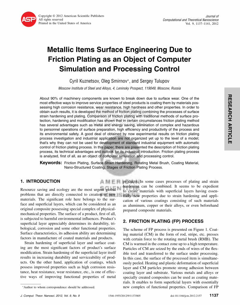
Fig. 3. Microstructure of aluminum coating: Top left—longitudinal section (×800); Right top and bottom—boundaries of aluminum plating adhesionwith steel substrate (×12,000).
to the steel substrate consist of particles more dispersethan those of core and surface, however distribution ofparticles in size covers rather wide range from 50 up to800 nm with separate but very rare particles up to 1500 nm.The “substrate-coating layer” boundary on the length ofthe investigated samples is rather non-uniform. At somesections it can be much diffused and is badly revealed(Fig. 3, top right). Sections with well developed boundaryof “wavy” type (Fig. 3, bottom right) are observed also.The transition zone on “substrate-coating layer” bound-ary can have laminated structure as well. The thickness ofthe layer with fine-disperse particles on “substrate-coatinglayer” boundary makes about 400 nm (Fig. 3, top left) andparticles are so fine, that are not resolved at magnificationsup to ×25,000. In the next layer of approximately samethickness particles in the size of 30� � � � �150 nm are ran-domly distributed in a homogeneous matrix.
4. DISCUSSION
As a result of metallographic analysis, it is possible toallocate in structure of coated samples three zones: thecoating layer itself, the transition layer between substrateand coating and the strengthened superficial layer of steelsubstrate. It is necessary to notice that friction plating onhard substrate (for example, steel with 0.55% C+2% Si)creates transition zone of minimal thickness. Similar pat-tern can be observed after friction plating of low-carbonsteel at small tightness and small number of passes. Para-meters of the tool also influences sizes and state of thetransition zone. While using “rigid” RMB (wire diam-eter dw = 0�4� � � � �0�5 mm) the transition zone happensto be more advanced than in the case of “soft” RMB(dw = 0�2� � � � �0�25 mm).Detailed studies have shown that friction plating cre-
ates at certain conditions nano-structured coatings both due
to disintegration of metallic superficial layers in the pro-cess of plating by metallic materials and whtn plating bycomposites containing strengthening phase in the form ofnano-particles. Disintegration of metallic particles in thecoating layer down to nano-sizes proceeds during repeated“shock-friction” acts of interaction between flexible ele-ments of RMB and coating material rendered on the sur-face of the item under processing, on the one hand, andbetween flexible elements of RMB and the surface of thisitem, on the other hand. As a result of mechanical activa-tion of nano-particles surfaces, strong connections betweenvarious by nature materials included in the coating arise;dense coating layer strongly linked to the surface of thecoated item is formed in this case.Detailed studies of structure and properties of nano-
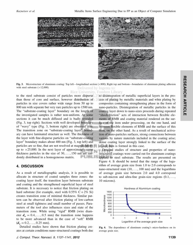
structured coatings were carried out for aluminum coatingsapplied to steel substrate. The results are presented onFigure 4. It should be noted that the range of the loga-rithm of average grain size from 1.0 to 2.0 corresponds tonano-structured state (10� � � � �100 nm) and the logarithmsof average grain size between 2.0 and 4.0 correspondto sub-micron and ultra-fine grain-size regions (0�1� � � � �10 microns).
0200400600800
1000120014001600
0 1 2 3 4 5
Mic
roha
rdne
ss
Logarithm of the average grain size
Hardness of Aluminium coating
Fig. 4. The dependence of aluminum coating’s micro-hardness on itsaverage grain size.
J. Comput. Theor. Nanosci. 9, 1137–1141, 2012 1139
Delivered by Ingenta to:Rice University, Fondren Library
IP : 95.25.76.51Mon, 01 Oct 2012 19:03:32
RESEARCH
ARTIC
LE
Metallic Items Surface Engineering Due to FP as an Object of Computer Simulation Kuznetsov et al.
Fig. 5. Mill rollers after friction plating.
Preliminary studies have shown that this new classof coatings obtained by FP process has excellent func-tional characteristics. Together with high hardness andwear resistance, these coatings possess also high corro-sion resistance and high heat resistance. Micro-hardness ofcoatings depending on their chemical composition changesfrom 1,100 MPa up to 14,000 MPa that provides their highwear resistance in any tribological situation. For example,hardness of aluminum nano-coating reaches 2,700 MPaat hardness of aluminum donor at the level of 300 MPa.Aluminum–zinc coatings with various ratios of Al and Znbuilds up corrosion resistance of steel in humid sea atmo-sphere 11� � � � �16 times as much; aluminum–nickel coat-ing builds up heat resistance of steel at 800 �C 9� � � � �12times as much.Friction plating is a powerful method of surface modi-
fication of metallic and even non-metallic (glass, ceramic)items. Due to friction plating, it is possible to increaseand to decrease friction coefficient, to improve both atmo-spheric corrosion resistance and fretting-corrosion resis-tance, to improve fatigue resistance, to restore worn-outsurfaces, to control surface texture, to decorate surfacesetc. As a result of friction plating, smooth and densecoating with good adhesion is formed on the surface ofmetallic items. FP method enables to make local harden-ing and to draw coatings on certain spots of large-sizedparts. It can find application in processing of mill rollers(Fig. 5), local areas of stamps, in restoration of worn-outfitting sizes of hydraulic systems’ parts etc. Testing of sam-ples has shown that service properties can be improved1�5� � � � �2�5 times as much.
5. CONCLUSION
Trends of Development. By now, it is collected a lot ofexperimental results on investigation of FP process andits industrial application. But these materials are not orga-nized yet up to the level of a physical and mathematicalmodels; that’s why they can not be used for developmentof standard industrial equipment with automatic control ofFP process. Below, it is presented the formal descriptionof FP process as the first step to creation of its computermodel, which is expected to be the basis for developmentof processing control system.FP process is assumed to consist of three stages:Stage 1. CM↔ RMB interaction (Fig. 6).
Fig. 6. Stage 1. Scheme of CM↔ RMB interaction.
At the Stage 1, RMB is pressed against the surface ofCM rod and rotating at high speed heats it to temperaturesnear its melting point. In this case, particles of CM aretrapped by wire ends of RMB and bring them to platingzone. The ability to control this stage of the process isdefined by the following parameters set at the input of theprocess:• Coating material (mechanical and thermal propertiesdepending on temperature; melting temperature).• Initial temperature of the coating material (T CM
0 �.• Features of RMB (material, diameter and length ofRMB wires, density of packing brushes).• Brush rotation speed (V ).• Tightness (N1).
At the output of Stage 1, there are forming indica-tors that characterize potentials of FP process, namely,temperature of CM at the beginning of its transfer onthe surface (T CM
1 ) and CM consumption per unit time(dM /dt).At the Stage 2 takes place interaction between CM and
the environment in the process of its transfer to the surfaceunder processing.The ability to control Stage 2 is determined by the
following parameters:• Coating material (mechanical and thermal propertiesdepending on temperature, melting temperature).• Temperature of CM at the beginning of its transfer tothe surface (T CM
1 �.• The ambient temperature (T A�.• The mass of CM on one wire of RMB (M1�.• Brush rotation speed (V ).• Path of single wire from the CM rod to the surface underprocessing (L).
At the output of Stage 2, it is formed the temperatureat the end of CM transfer to the surface under process-ing (T CM
2 ).Stage 3. Interaction RMB + MP ↔ surface under
processing (Fig. 7).At the Stage 3, the wires of RMB with particles of
CM on the ends interact with the surface under process-ing. In the beginning of the stage, CM is applied on the
1140 J. Comput. Theor. Nanosci. 9, 1137–1141, 2012
Delivered by Ingenta to:Rice University, Fondren Library
IP : 95.25.76.51Mon, 01 Oct 2012 19:03:32
RESEARCH
ARTIC
LE
Kuznetsov et al. Metallic Items Surface Engineering Due to FP as an Object of Computer Simulation
original surface of the workpiece consolidating on it inaccordance with parameters of adhesion between substratematerials (SM) and CM. Further, after formation of theprimary coating layer, CM is applied on this layer sev-eral times, depending on the number of passes; this createsa laminate coating, the density of which depends on theparameters of adhesion between the layers of CM, whichhave different temperatures.The ability to control Stage 3 is determined by the
following parameters:• Coating material (mechanical and thermal propertiesdepending on temperature; melting temperature).
• Features of RMB (material, diameter and length ofRMB wires, density of packing brushes).• The temperature of the CM at the end of its transfer onthe surface under processing (T CM
2 �.• Brush rotation speed (V ).• Tightness (N ).• The mass of CM on one wire of RMB (M1�.• Consumption of MP per unit time (dM /dt).• Surface temperature of the workpiece (T WP
0 �.• Number of passes (n).
At the output of Stage 3, there are forming indica-tors that characterize final results of FP process, namely,the main characteristics of structure and properties of thecoating and its thickness (�).Computer model for simulation of FP process is now in
the process of development.
Acknowledgment: Detailed investigation of FP processwas started due to support of ISTC in frames of the project#2703 finished in 2007.
References
1. L. S. Belevskii, S. A. Tulupov, O. M. Smirnov, J. Gordon, andI. L. Belevskii, Metallurgist 50, 497 (2006).
2. L. S. Belevskii, S. A. Tulupov, O. M. Smirnov, J. Gordon, andI. L. Belevskii, Metallurgist 50, 555 (2006).
Received: 10 August 2010. Accepted: 15 October 2010.
J. Comput. Theor. Nanosci. 9, 1137–1141, 2012 1141