Page 1
Metallographic preparation and degradation of the t-phase
(FeAl2S4) formed after high-temperature oxidation±
sulfidation of Fe±Al alloys
S.W. Banovic*, J.N. DuPont, A.R. Marder
Department of Materials Science and Engineering, Lehigh University, Bethlehem, PA 18015, USA
Received 10 January 2000; received in revised form 1 June 2000; accepted 1 June 2000
Abstract
The stability of corrosion products formed after high-temperature exposure of an Fe±5 wt.% Al alloy in an
oxidizing±sulfidizing environment was investigated both during metallographic preparation and subsequent
exposure to the ambient environment. The primary phases formed were an outer layer of iron sulfide (Fe1 ÿ xS)
and an inner layer composed of t-plates (FeAl2S4) and iron sulfide particles. No difficulties were found
concerning the stability of the iron sulfide phases, but it is known that the t-phase is easily hydrolyzed by water.
Therefore, standard metallographic procedures where water is used as a lubricant and/or cleansing solution during
preparation could not be exercised. Using scanning electron microscopy, energy dispersive spectroscopy, and
electron probe microanalysis, the effect of the use of various lubricants and/or cleansing solutions was examined
in order to produce good quality, polished cross-sections of the corrosion scales. The best results were obtained
using 200-proof dehydrated ethyl alcohol as the lubricant and cleansing solution. It was also observed that post-
exposure of polished samples to the ambient environment degraded the microstructure with time. It is believed that
moisture from the air reacted with the t-phase, resulting in the evolution of hydrogen sulfide gas. D 2000 Elsevier
Science Inc. All rights reserved.
Keywords: Metallographic preparation; Degradation; FeAl2S4; High-temperature oxidation; Sulfidation; Fe± Al alloys
1. Introduction
An important aspect in determining the corrosion
behavior of a material is the post-exposure character-
ization of the corrosion products that develop. Ana-
lysis typically requires observing the cross-sectional
microstructure and determining the chemical compo-
sition in this orientation using electron probe micro-
analysis. This technique requires a flat, polished
surface in order to gain quantitative chemical infor-
mation. However, the corrosion products may not be
stable with respect to the lubricants and/or cleansing
solutions, usually water, used during standard metal-
lographic procedures to prepare polished cross-sec-
tions. Many corrosion phases containing main and
alloying elements standard in materials typically used
for high-temperature applications are found to have
some solubility in water. Sulfides and sulfates of
aluminum (Al2S3, Al2(SO4)3), iron (FeSO4,
Fe2(SO4)3), and nickel (NiSO4) are a few examples
1044-5803/00/$ ± see front matter D 2000 Elsevier Science Inc. All rights reserved.
PII: S1 0 4 4 - 5 8 0 3 ( 0 0 ) 0 0 0 8 2 - 6
* Corresponding author. Tel.: +1-610-758-4270.
E-mail address: [email protected] (S.W. Banovic).
Materials Characterization 45 (2000) 241±249
Page 2
[1]. To substantiate this point, problems were en-
countered by Mrowec and Wedrychowska [2] during
the preparation of corrosion scales after sulfidation of
Fe±Cr±Al alloys at high temperature. They ob-
served that the aluminum sulfide corrosion product
degraded in a matter of hours when exposed to
moisture from the air. A similar problem was also
experienced during research conducted on Fe±Al
alloys exposed to high-temperature oxidizing±sulfi-
dizing atmospheres [3±5]. Surface reactions with the
gaseous environments led to the development of a bi-
layered scale composed of multiple sulfide phases.
While the outer iron sulfide phase was stable with
respect to the ambient environment and metallo-
graphic lubricants, the inner layer containing the t-
phase was not. This paper will briefly review the
general characteristics of the t-phase that was ob-
served to develop in the corrosion product micro-
structure, followed by problems associated with
preparing the samples using standard metallographic
techniques and its degradation once exposed to
ambient air. A procedure used to minimize degrada-
tion of the corrosion products during metallographic
procedures will also be described.
2. Experimental procedure
Fe±Al alloys containing 5 wt.% Al were pro-
duced by arc melting high purity components under
an argon atmosphere then drop casting into a water-
cooled copper mold at Oak Ridge National Labora-
tory (Oak Ridge, TN). Sulfidation experiments were
conducted using a Netzsch STA 409 high-tempera-
ture thermogravimetric balance. Before testing, spe-
cimens were cut to dimensions of 10�10�2 mm,
ground to 600 grit with silicon carbide papers,
ultrasonically cleaned in methanol, and weighed to
the nearest mg. Samples were heated at a rate of
50°C/min and isothermally held at 700°C for 50 h.
An argon ± base gas mixture of 0.1% H2 ± 1.0%
H2S±5 ppm O2 (by volume percent) was used with
the partial pressures of oxygen [pO2] and sulfur
[pS2] set at 10ÿ25 and 10ÿ4 atm, respectively, at
Fig. 1. Polished cross-sections of an Fe± 5 wt.% Al alloy corroded at 700°C for 50 h in an oxidizing/sulfidizing atmosphere. (a)
Light micrograph of the bi-layered scale. (b, c, and d) Secondary electron images of the inner scale. The t-phase (dark plates with
light-colored striations) can be seen, as well as light gray particles of iron sulfide (with arrow in (d)) and porosity (black).
S.W. Banovic et al. / Materials Characterization 45 (2000) 241±249242
Page 3
temperature. The oxygen partial pressure was mea-
sured by means of a solid state oxygen cell and the
sulfur partial pressure was calculated using the
SolGasMix program [6]. The corrosion samples
were mounted in cold-setting epoxy and allowed
to cure. Metallographic preparation consisted of
grinding to 1200 grit with silicon carbide papers
using various lubricants and cleansing solutions.
Subsequent polishing with 1.0-mm diamond paste
on a low-nap cloth was the only polishing step.
Samples were dried using a cold air gun. Analysis of
the cross-sectional morphology of the corrosion
Fig. 2. EPMA data for the corrosion products and underlying substrate overlaid on the Fe± Al± S ternary phase diagram at 900°C
from Ref. [8].
Fig. 3. Schematic diagrams showing (a) the direction of grinding and polishing of the major face and (b) the corrosion scale in
cross-section, indicating the various planes that were analyzed.
S.W. Banovic et al. / Materials Characterization 45 (2000) 241±249 243
Page 4
samples was conducted with light optical micro-
scopy and scanning electron microscopy. Chemical
analysis of the corrosion products was obtained with
an energy dispersive spectrometer (EDS) and an
electron probe microanalyzer (EPMA). For the latter,
Ka X-ray lines were analyzed and counts converted
to weight percentage using a f(rz) correction
scheme [7].
3. Results and discussion
3.1. General corrosion microstructure
Fig. 1 shows a typical cross-section of the bi-
layered corrosion scale that formed on the Fe±5 wt.%
Al alloys after exposure to high-temperature oxida-
tion/sulfidation environments. The porous outer layer
consisted of irregularly shaped plates of iron sulfide
(Fe1ÿxS). The inner scale (Fig. 1b and c) was found to
be composed of dark plates and light particles (shown
by arrows in Fig. 1d). A fair amount of porosity (the
black regions in Fig. 1d) was observed due to the
outward diffusion of iron to form the iron sulfide
surface scale at the gas/scale interface, while the
diffusion of sulfur inward along the phase boundaries
occurred for further development at the scale/alloy
interface. To obtain an overall average composition of
the inner scale, microprobe scans of roughly 25 mm2
were conducted. The results placed the composition
for the inner scale in the two-phase region of Fe1ÿxS
and t-phase (FeAl2S4, a spinel-type compound) (Fig.
2). The dark plates were observed to have light-
colored striations parallel to the lengths, Fig. 1d,
and while the individual phases were too fine to
analyze, the overall composition located the plates
in the center of the t-phase region, Fig. 2. The
striations observed in the t-phase plates may be due
to a decomposition process that occurred upon cool-
ing from high-temperature exposure. Mrowec et al.
[2,9] surmised that this type of decomposition oc-
curred during sulfidation experiments on Fe ± Cr
alloys, during which a complex Fe(FexCr2 ÿ x)S4
spinel was believed to have decomposed into sulfides
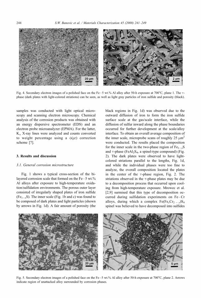
Fig. 4. Secondary electron images of a polished face on the Fe± 5 wt.% Al alloy after 50-h exposure at 700°C, plane 1. The t-
phase (dark plates with light-colored striations) can be seen, as well as light gray particles of iron sulfide and porosity (black).
Fig. 5. Secondary electron images of a polished face on the Fe ±5 wt.% Al alloy after 50-h exposure at 700°C, plane 2. Arrows
indicate region of unattacked alloy surrounded by corrosion phases.
S.W. Banovic et al. / Materials Characterization 45 (2000) 241±249244
Page 5
that were more stable at room temperature (FeCr2S4,
FeS, and Cr2S3) after cooling down from the expo-
sure temperature. The light-colored particles (with
arrow in Fig. 1d) were also too small to analyze
quantitatively using the EPMA, but qualitative EDS
analysis showed high counts of iron and sulfur with
Fig. 6. Secondary electron images of a polished face on the Fe± 5 wt.% Al alloy after 50-h exposure at 700°C, plane 3. (a) Attack
within grains and grain boundaries; (b) four growth directions found in an individual grain; (c) six growth directions found in an
individual grain.
S.W. Banovic et al. / Materials Characterization 45 (2000) 241±249 245
Page 6
very low counts of aluminum, suggesting that it was
iron sulfide with some dissolved aluminum. EPMA
data could not be obtained from the plate tips
extending into the alloy due to their size (bottom of
Fig. 1b), but high counts of iron, aluminum, and
sulfur were found, indicating the possible continua-
tion of the t-phase.
In order to determine the exact shape of the two
phases within the inner scale, a major face of the
sample was polished as shown schematically in Fig.
3a, in addition to reviewing the results of the cross-
sectional morphologies. Fig. 3b shows a schematic of
the corrosion scale in cross-section indicating the
various planes that were analyzed. The middle of
the inner scale (plane 1) revealed the plate morphol-
ogy of the t-phase and the particle nature of the iron
sulfide, Fig. 4. Again, the porosity in the layer and
the striations of the t-phase can be seen. Closer to the
alloy±scale interface (plane 2), the attack of the
corrosion products into the substrate can be viewed,
Fig. 5. EPMA data for the unattacked alloy (with
arrow in Fig. 5b) near the plates showed no sulfur
present and the EDS data for the light-colored
particles showed high counts of iron and sulfur with
low counts of aluminum. Further polishing led to the
removal of the inner corrosion scale, with the sub-
strate and plate protrusion left to be observed (plane
3), Fig. 6. The t-phase can be seen to attack the
substrate both in the grains and grain boundaries.
Analysis of numerous grains revealed a crystallo-
Fig. 7. Light optical micrographs of cross-sections polished by techniques using three different media: (a) methanol; (b)
kerosene and methanol; and (c) 200-proof (dehydrated) alcohol.
S.W. Banovic et al. / Materials Characterization 45 (2000) 241±249246
Page 7
graphic orientation of the plates with the substrate
that may suggest easy growth directions for the
corrosion product. Most grains displayed only four
growth orientations (Fig. 6b), while some had six
directions due to a few plates being oriented in a
slightly different manner (Fig. 6c).
3.2. Sample preparation
Many different types of preparation techniques
were tried in order to obtain good quality, polished
cross-sections of the corrosion scales for quantita-
tive chemical analysis. It is known that the t-
phase is easily hydrolyzed by water [10], and
therefore, standard metallographic procedures in
which water is used as a lubricant and/or cleansing
solution during preparation could not be employed.
Investigations were thus conducted to find a sui-
table preparation method.
Fig. 7 shows light optical micrographs of
samples prepared using different media. All sam-
ples were prepared in the same manner, with the
exception of lubricant or cleansing solution, and
pictures taken immediately following preparation
(within 5 min). Fig. 7a shows the structure after
preparation using methyl alcohol for the lubricant
and cleansing solution. The structure of the inner
scale appeared to be smudged and attempts to
obtain photomicrographs with sharp definition
were difficult. This was primarily due to loss of
the t-phase during the preparation procedure and
the resulting difference in depth of field of the
structure. Fig. 7b displays the structure after pre-
paration with kerosene as the lubricant and metha-
nol as cleansing solution. The structure appearance
was slightly less smudged, but again, distinctive
features could not be made out in the inner scale.
Fig. 7c shows the microstructure after preparation
with 200-proof (dehydrated) ethyl alcohol as the
lubricant and cleansing solution. Features in the
inner scale (in terms of the t-plates and iron
sulfide particles) can be clearly distinguished and
the smudged appearance was not observed. How-
ever, these results were obtained only after using a
fresh bottle of alcohol. Use of an aged bottle
produced no better results than with the methanol.
It was presumed that moisture became dissolved in
the alcohol upon exposure to ambient air and
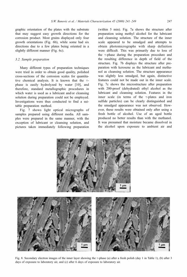
Fig. 8. Secondary electron images of the inner layer showing the t-phase (a) after a fresh polish (day 1 in Table 1), (b) after 3
days of exposure to laboratory air, and (c) after 6 days of exposure to laboratory air.
S.W. Banovic et al. / Materials Characterization 45 (2000) 241±249 247
Page 8
attacked the structure during the preparation pro-
cedure. Other lubricants or cleansing solutions
used were water, general grade ethyl alcohol,
isopropyl alcohol, and various dry techniques.
However, those results were less satisfactory than
the ones presented here.
3.3. Degradation in air
Upon re-examination of the polished samples after
a few days, the observance of the `̀ smudged'' ap-
pearance was again found. It was also noted that upon
opening the desiccator lid, a strong odor of hydrogen
sulfide gas (rotten eggs) was released. In addition,
electron probe microanalysis of the same sample
tested days apart detected a relatively large amount
of oxygen in the structure at the later time. Thus, it
was believed that the sample was degrading while
exposed to ambient air, even with the use of fresh
desiccant. Therefore, a study was conducted to de-
termine the degradation of the t-phase upon exposure
to ambient air.
A freshly polished sample was characterized
using scanning electron microscopy (Figs. 8a and
9a) and electron probe microanalysis (day 1 in
Table 1) immediately after being prepared using
the above technique. The areas of analysis were
located in the middle of the inner scale and at the
alloy±scale interface. After being exposed to la-
Table 1
EPMA data for the degradation of the t-phase, Fe± 5 Al at 700°C for 50 h
Time Fe (wt.%) Al (wt.%) S (wt.%) O (wt.%)
Stoichiometric
composition
23.5 22.7 53.9 0.0
Day 1 24.5 � 0.7 21.9 � 0.7 53.3 � 0.7 0.8 � 0.4
Day 3 23.4 � 0.8 21.6 � 0.7 49.1 � 0.5 4.8 � 0.3
Day 6 24.8 � 0.5 22.3 � 0.4 46.6 � 0.6 5.1 � 0.4
Fig. 9. Secondary electron images showing the alloy±scale interface and protruding t-phase (a) after a fresh polish (day 1 in
Table 1), (b) after 3 days of exposure to laboratory air, and (c) after 6 days of exposure to laboratory air.
S.W. Banovic et al. / Materials Characterization 45 (2000) 241±249248
Page 9
boratory air for periods of 3 and 6 days, the sample
was re-analyzed using the above mentioned techni-
ques. These results can be found in Figs. 8 and 9,
as well as the EPMA data in Table 1. It can be
seen that the structure of the t-phase did not appear
to change significantly after 3 days of exposure but
the oxygen content had increased to about 5 wt.%,
concurrent with a decrease in the sulfur content.
Similar results were obtained after an additional 3
days of exposure. From this analysis, it is believed
that the t-phase may be reacting with moisture
from the atmosphere according to the reaction
(Eq. (1)):
FeAl2S4 � 3H2O�g� ! Al2O3 � FeS� 3H2S�g�:�1�
The release of hydrogen sulfide from the structure
would account for the odor upon opening the
desiccator. Mrowec and Wedrychowska [2] also
observed the degradation of corrosion scales when
sulfidizing Fe±Cr±Al alloys. They found that the
Al2S3 reaction product that formed, which also reacts
with moisture, degraded in a matter of hours.
4. Summary
The importance of obtaining good quality, po-
lished cross-sections of the corrosion scale is an
integral part of understanding the high-temperature
corrosion behavior of Fe±Al alloys in an oxidiz-
ing/sulfidizing environment. The reaction of the
corrosion products with both the environment
and the materials used to prepare the cross-sec-
tions is of equal importance. This research has
yielded a method for preparing metallographic
cross-sections of corrosion scales that may react
and/or dissolve when exposed to water, either from
the ambient air or in the lubricant/cleansing solu-
tion. The use of 200-proof (dehydrated) ethyl
alcohol was found to retain the t-phase, while
the stability of the iron sulfide phase was never a
concern. In addition, this work has shown the
importance of analyzing the structure in a timely
manner as reactions with moisture from ambient
air can degrade the corrosion products over time.
Acknowledgments
This research was sponsored by the Fossil
Energy Advanced Research and Technology De-
velopment (AR&TD) Materials Program of the US
Department of Energy, under contract DE-AC05-
96OR22464 with the Lockheed Martin Energy
Research. The authors wish to thank V.K. Sikka
and P.F. Tortorelli from ORNL for the cast Fe±Al
alloys used in corrosion testing and technical
discussions, respectively. Suggestions by A.O.
Benscoter regarding sample preparation techniques
were well received.
References
[1] Lide DR, editor. CRC Handbook of Chemistry and
Physics, 76th edn. New York, NY: CRC Press, 1995.
pp. 4-37± 98.
[2] Mrowec S, Wedrychowska M. Kinetics and mechan-
ism of high-temperature sulfur corrosion of Fe ±Cr ±Al
alloys. Oxid Met 1979;13(6):481 ±504.
[3] Banovic SW, DuPont JN, Marder AR. The role of
aluminum on the weldability and sulfidation behavior
of iron ± aluminum claddings. Weld J January
1999;17(1):23s± 30s.
[4] Banovic SW, DuPont JN, Marder AR. High tempera-
ture sulfidation behavior of low Al iron ± aluminum
compositions. Scr Mater 1999;38(12):1763±7.
[5] Banovic SW, DuPont JN, Marder AR. The effect of
aluminum content on the corrosion behavior of Fe ±Al
alloys in reducing environments at 700°C. Metall
Trans 2000;31A(7):1805± 17.
[6] Roine A. HSC Chemistry, Version 3.02. Pori, Finland:
Outokumpu Research Oy, 1998.
[7] Goldstein JI, Newbury DE, Echlin P, Joy DC, Romig
AD Jr., Lyman CE, Fiori C, Lifshin E. Scanning Elec-
tron Microscopy and X-ray Microanalysis, 2nd edn.
New York, NY: Plenum, 1992.
[8] Raghavan V. Phase Diagrams of Ternary Alloys, Pt 2.
Calcutta, India: The Indian Institute of Metals, 1988.
pp. 5 ± 9.
[9] Mrowec S, Walec T, Werber T. High-temperature sul-
fur corrosion of iron ± chromium alloys. Oxid Met
1969;1(1):93± 120.
[10] Macintyre JE, editor. Dictionary of Inorganic Com-
pounds (Vol. 1). New York, NY: Chapman & Hall,
1993. p. 52.
S.W. Banovic et al. / Materials Characterization 45 (2000) 241±249 249