53
Welding Metallurgy Metallurgical Effects of . the Weld Thermal Cycle Lecture 9 p1

Welding Metallurgy
Metallurgical Effects of.the Weld Thermal Cycle
Lecture 9 p1
9
Lecture Scope
• Metallurgical phenomena involved in welding.
• Effects on weld and HAZ properties
p2
(
(
Weld and Heat Affected Zone
A welded joint consists of:
• weld metal- melted and re-solidified base metal mixed with filler metal
(if added)
• heat affected zone (HAZ)- the region around the weld whose properties or
microstructure are affected by the thennal cycle- reheating also alters the structure of under1ying weld
metal in multi-pass welds
• and base metal
Lecture 9 p3

9
Metallurgical Phenomena
• Welding is a complex process that involves:- Gas-metal & slag-metal reactions- Solidification- Metallurgical reactions in the solid state
• annealing & recovery• grain growth• precipitation• phase transformation
• These metallurgical phenomena control weldstrength and ductility
p4
(

Gas-Metal Reactions
• Reactive gases (especially N2, 02, H2) may be present inthe arc atmosphere due to surface contamination,imperfect shielding, or purposeful additions.
• These gases dissociate in the arc and react rapidly withthe high temperature, turbulent liquid metal in the weldpool.
• Once dissolved in the metal, oxygen and nitrogen combinewith deoxidizers such as Si or AI. The resulting oxides ornitrides remain as small indusions in the weld metal.
• Excess dissolved gas is rejected during solidification andmay cause porosity (e.g. hydrogen in AI)
• Dissolved hydrogen can cause cracking in steels
Lecture 9 p~

9
Slag-Metal Reactions
• Fluxes and slags interact with the molten weld metal
• The slags used in flux shielded processes are designed toabsorb deoxidation products and other contaminants -
• The cleanliness and properties of the weld metal depend onthe oxidation potential of the arc atmosphere and on thetype of flux
• Highly basic fluxes reduce weld metal oxygen content andgive superior notch toughness. Acid fluxes tend to givehigher oxygen contents and poor notch toughness.
• Fluxes may also be used to modify weld metal compositionby transfer of alloying elements from the slag to the liquidmetal
--~---- -
p6
(
Dilution
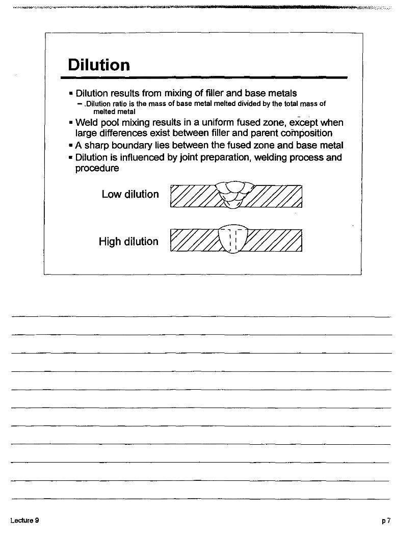
• Dilution results from mixing of filler and base metals- .Dilution ratio is the mass of base metal melted divided by the total mass of
melted metal
• Weld pool mixing results in a uniform fused zone, except whenlarge differences exist between filler and parent composition
• A sharp boundary lies between the fused zone and base metal• Dilution is influenced by joint preparation, welding process and
procedure
Lowdilution~
High dilution~
Lecture 9 P7

9
Solidification
• Factors controlling the solidification modesof metals are:- temperature gradient- composition- rate of solidification
p8
(
(

Constitutional Undercooling
The variation in composition, temperature, and freezingtemperature in front of a solid liquid interface can make aplane interface unstable
Lecture 9
Distance
T_-~,-.:;==--- TL
Distance
p9
Cellular growth (
,9
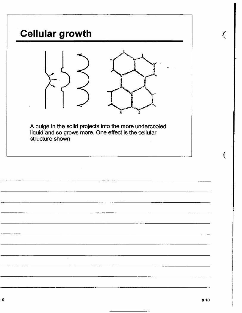
A bulge in the solid projects into the more undercooledliquid and so grows more. One effect is the cellularstructure shown
P 10
(
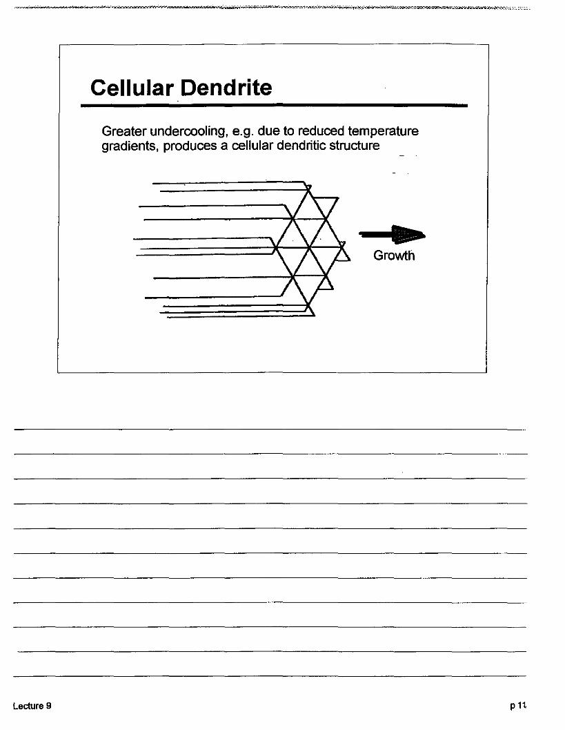
Cellular Dendrite
Greater undercooling, e.g. due to reduced temperaturegradients, produces a cellular dendritic structure
Lecture 9
-...Growth
pH
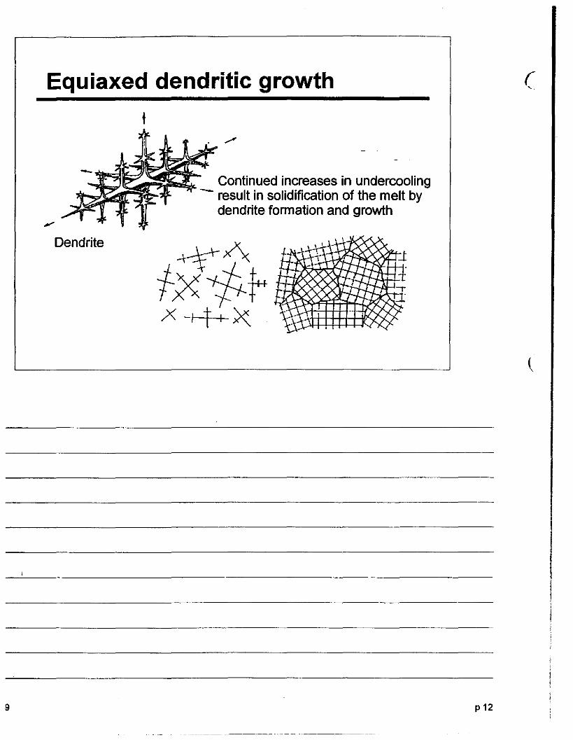
Equiaxed dendritic growth
t
Continued increases in undercooling- result in solidification of the melt by
dendrite formation and growth
(,
9
Dendrite
p12
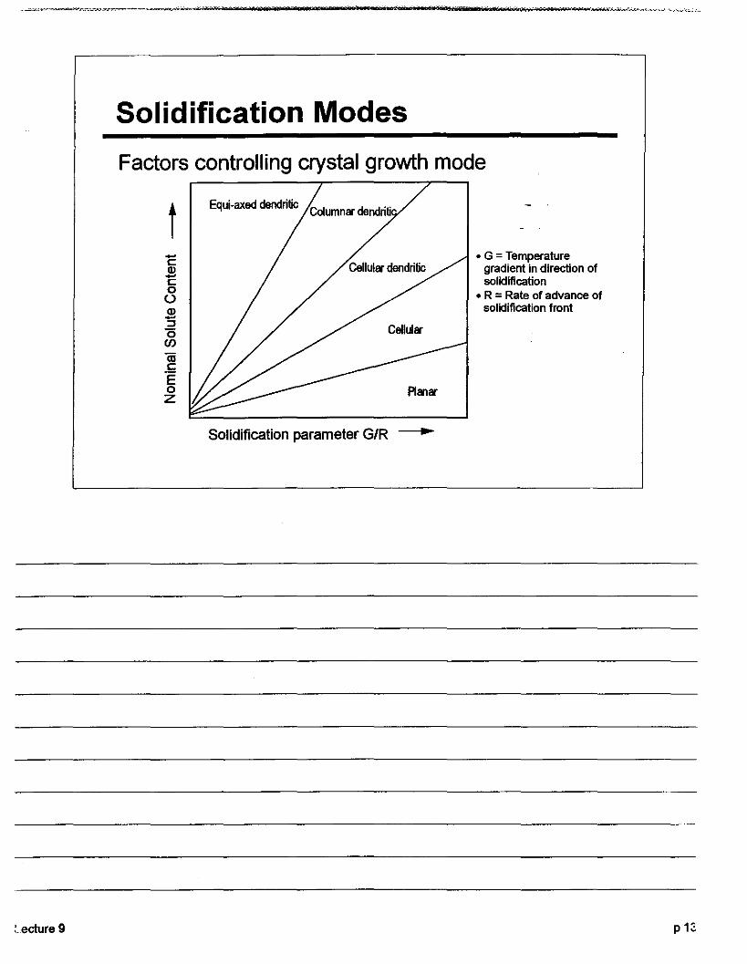
Solidification Modes
Factors controlling crystal growth mode
tC2c:o()
2:::J"0(J)
iiic:°Eoz
Equi·axed dendritic Columnar dendriti
Cellular dendritic
Cellular
• G =Temperaturegradient in direction ofsolidification
• R = Rate of advance ofsolidification front
Lecture 9
Solidification parameter G/R ----
P 13

Epitaxial Growth (
J.F. Lancaster Metallurgy of WeldingGeorge Allen & Unwin, 1980
.• The crystals in solidifyingweld metal nucleate ongrains in the surrounding·solid.
• Crystals whose orientationsare favourable for growthdominate.
• Termed "competitiveepitaxial growth."
• Results in adirectionalsolidification structure.
I,(c) cellulardendritic
(a} (b) cellularplanar
base metal solidified weld melal grains
I
(d) columnardendritic
(
·9 p14
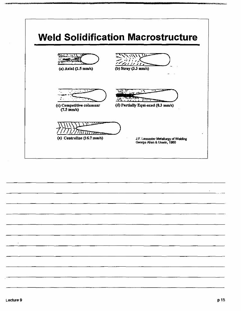
Weld Solidification Macrostructure
(a) Axial (2.5 mmls)
.....: )..~,.~~~~,c: ..,.. -.:. '.". ".' .. :
(c) Competitive columnar(7.5 mmls)
(b) Stray (3.3 mmls)
i!i;:;,i .'::, )(d) Partially Equi-axed (8.3 mmls)
Lecture 9
ll....l..!..»nm\>»i!J1lU:rm:=!:i.:il2Z::::::::_. )
(e) Centreline (16.7mmls) J.E Lancaster Melall..-gy of WeldingGeorge Allen & Unwin, 1980
p15
9
Reactions in the solid phase
• Annealing, recrystallization & grain growth• Precipitation hardening• Phase transformation
p16
(
(

Lecture 9
Annealing and Recrystallization
• Welding has little effect on the properties of annealedsingle phase alloys that are strengthened by solutkJnstrengthening- e.g. hot rolled low carbon steels, austenitic stainless
steels, commercially pure aluminum, titanium andzirconium.
• However, when such materials are strengthened by coldwork, the weld thermal cycle induces recrystallization andgrain growth
• The welding heat anneals the heat affected zone, reducingits strength and increasing ductility
pH
9
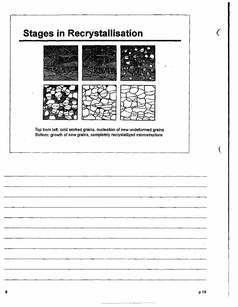
Stages in Recrystallisation
Top from left: cold worked grains, nucleation of new undeformed grainsBottom: growth of new grains, completely recrystallized microstructure
p18
(
(
)-nnw ± _of f", l"-M
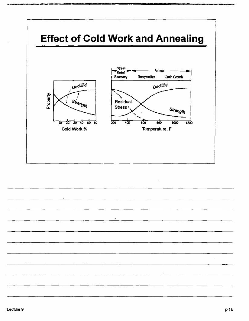
Effect of Cold Work and Annealing
~StresS AnnealRelief ...... ~II Recovery Recrystallize Grain Growth J
OUc'U\i~ ouc\i\i~
~tilC.e
Q..
Strength
10 30 40 60 10 200 400 800 lDOD 1200
Cold Work % Temperature, F
Lecture 9 pH,

.9
Precipitation Hardening
• Precipitation hardening alloys are strengthened-byfineprecipitates dispersed in the matrix -- AI, Cu, stainless steel
• PH alloys are hardened by heating to a high temperature,at which the solutes are taken into solution, andquenching, followed by ageing at a lower temperature topermit the development of fine precipitates.
p20
(
I

-------------------------------_....__....._-----~""""'-.;;,.-:-"""-..-".,.,-
Weld & HAZ in PH alloys
A
Lecture 9
z .....QzlIlO~N--------Z
OwF=z30 ll:! T,0'" ~!!L «_lew a::
00 ~~~ ~OO"O<N :::;:
0 .. - .....'Iun fil I-
~:::.-::: ti ....•••••••• UI:H••••••• ll: ~........ .-~(/):>
cr-B
%B-- B
p21
"e9
Effects of Welding on PH Alloys
• The weld thennal cycle disrupts the microstructure of alloyswelded in the hardened condition
• The weld metal and high-temperature HAZ are in effect solution treated.
• In parts of the HAZ that reach temperatures below thesolution temperature, the precipitates coarsen, causing lossof strength. This over-ageing can be recovered only by fullheat treatment
• However, precipitation hardening alloys can be welded withreasonable success in the solution-treated condition,followed by an ageing treatment after welding
p22
(

Phase Transformations
• The properties of steels are influenced by the phasetransformations they undergo on heating and coOling
• Iron solidifies as a body-centred crystal structure nameddelta-ferrite
• On further cooling it transforms to a face-centred cubiccrystalline phase called gamma iron or austenite
• The austenite subsequently transforms back to abody-centred cubic form known as alpha iron or ferrite
Lecture 9 p22
Phase Transformations
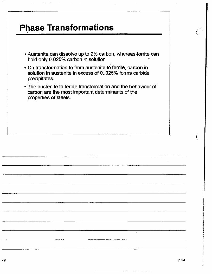
• Austenite can dissolve up to 2% carbon, whereas-ferrite canhold only 0.025% carbon in solution
• On transformation to from austenite to ferrite, carbon insolution in austenite in excess of 0..025% forms carbideprecipitates.
• The austenite to ferrite transformation and the behaviour ofcarbon are the most important determinants of theproperties of steels.
p24
(
(

Fe-C of 1600 °c2800
Phase /) Uquid 1400
Diagram 2400
1200
• The concentration of2000 y
(Austenite) 1000carbon alters the Y+csbides
temperatures at 1600800
which phase changes"3OCCU[ 1200 600
• This phase diagramsshow the equilibrium 800 a (Ferrite) + carbides 400
phases at variouscompositions and 400 200temperatures
1 2 3 4 5Weight % Carbon
Lecture 9 p25
~9
Kinetic effects
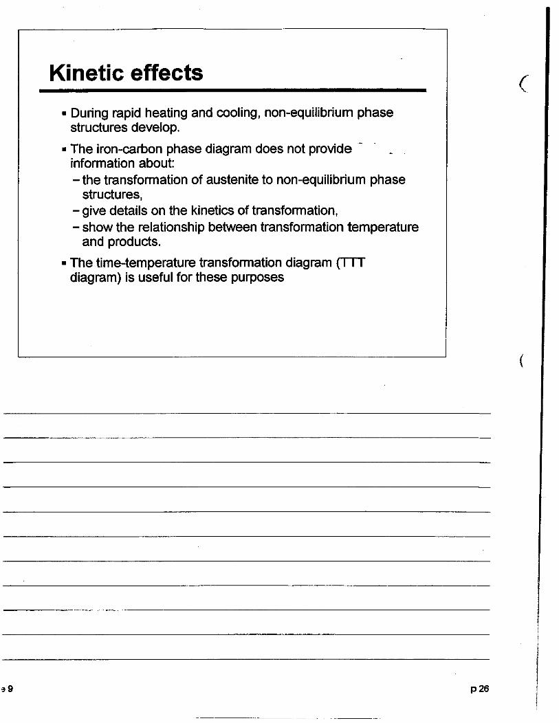
• During rapid heating and cooling, non-equilibrium phasestructures develop.
• The iron-carbon phase diagram does not provide information about:- the transformation of austenite to non-equilibrium phase
structures,- give details on the kinetics of transformation,- show the relationship between transformation temperature
and products.
• The time-temperature transformation diagram (TTTdiagram) is useful for these purposes
.._---_...._-
p26
(
(

Lecture 9 p27

Transformation products in steel
89
Pearlite
Upperbainite
I .: (oe l ""Q tide~ , J
1'.,[,' 'CtS,I'cv.J
Lowerbainite
I
~nucl.....
C-enrithcd T
11-rerrilenucl....
p28
(
(

Continuous CoolingTransformation (CCT) Diag.;..ra_m~_
800
500
J.F. Lancaster Melall"ll)' of WeldingGeorge Allen & UnwIn, 19S0
Lecture 9
0400S!-----:l:lO,.-----:!:I}!::----:40~~S)=--=IO,..-J
Time(s)
P2f.

e9
CCT diagram
a. inclusion formationb. solidification of liquid to delta ferritec. fully austenitic structured. nucleation of elleUiQAlQ",llie ferritee. growth of ferritef. Widmanstatten ferrite fonnationg. acicular ferrite formation
K. Munclra, T. DeBroy, 5.5. Babu and SA OaYld: WakingJollllOl R....'ch SUpplomont April 1997, 1635-171.
~ I--J
.I" t ..10'" ~ 10'
-(0)
p30
(
(

Effect of Transformation Temp
200 400 600 800 C
180
~12' ro
160 a...s::::; :::2:...... 140 10< .s::::;C>
H"rd"lrss ? C......C>
~ UO C...... IIlJ( ~en -.S!2 100 en•"Ci)
MARTCNsL ' FERRITE
eo< .S!2c 80 "Ci)
~ c
.$ 80 ~ro <IQ(
.$E 40 IB~NnEfEARLnE roE E=> :zo +=>
20 501.-....J...--'''--..J...--lL.-.J....~:-:-I
400 800 1200 1600 F
Temperature of Maximum Rate ofTransformation
1'V)c.~~O''''"''~""COOLl(l(,. k/I-r-r
Lecture 9 p31
HAZ Structure in SteelsT, OF T, 'c
(
1700
1500
1300
'100
1.0 2.0 3.0 4.0%C
IRON.cARBON DIAGRAM
II
FERRITE +CARBIDEII
900
~~--"''f-=--------1700
500
432 ',yz&./O.30%C STEEL ,~
BASE METAL 'HAZ
/
MAXIMUM 1TEMPERATURE
IF
(
,9 p32
---------.- - ---

HAZ Structure in Steels
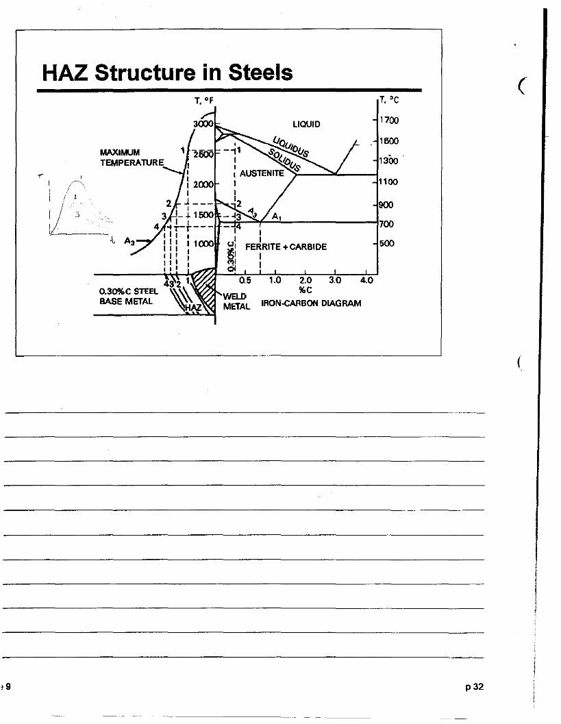
• In the preceding figure, Regions 1 and 2 were heated aboveA3 and were transformed fully into austenite and back oncooling -
• Region 1 exceeded the temperature at which the carbideparticles that pin the austenite grain boundaries dissolve,causing austenite grain growth
• Region 3 was heated between the A1 and A3 temperaturesand partially transformed to austenite
• Region 4 did not exceed A1 and is termed the "sub-criticalHAZ." Some annealing or tempering may occur in thisregion.
Lecture 9 p33

~ ',- f
METALLOGRAPHY01' WELDSIN CARBONMANGANESESTEELSSlide set number 7
~mTIrnrnrnrnrnTIrnrn)1 mrnTI~~,
I
~/iThe Welding InstituteAbington Hall Abington CambrIdge CB 1 6AL UK

Weld metals
Principal microstructures of weld metals 3
Slide number
Heat affected zones
0712 Heat affected zone 16"0713 Coarse grained super-
critical HAZ 180714 Fine grained super-
critical HAZ 190715 Intercritical HAZ 200716 Subcritical HAZ 2l:Principal microstructunal constituentsin HAZs 23'Typical microstructures in HAZs 2t0717- Most <rapid cooling ~0722 Least. rapid cooling :11
Slides. wallcharts 3JKey to identification letters :Ill
ISBN 0 85300142 1 INTRODUCTION
07010702 }0703
0704, 07050706
0707 }070807090710 }0711
Single pass welds
{
Acicular ferriteand grain boundaryferriteFerrite with aligned M-A-CRetained martensite andausteniteHigh heat input welds
Heat treatmentMultipass welds
numbe
1
56
78
9~{ ~~\
13
{1415
-.'.- ~- -"~--'~-'-"--~'-------
~ .'"'""'\.

lNTKOlJUCTlON
Steels alloyed with carbon (C) (0.1-0.25%) andmanganese (Mn) (1-2%) are used in many applications as economical constructional materials, andare often welded.
The mechanical properties of weld metals inC-Mn steels (such as strength and toughness) aredetermined primarily by microstructure, which isdependent on factors such as chemical composition,thermal history and the type and quantity of anynon-metallic inclusions. The microstructure isrevealed by the standard metallographic techniqueof sectioning, polishing and etching, followed byexamination under a microscope. The normal etchantis nital (2% nitric acid in ethyl alcohol, requiringestablished safety precautions), and was used inthe preparation of all the samples except thatshown in slide 0706.
In assessing the properties of C-Mn steel weldmetals. it is important to be able to recognise thevarious microstructural types; these slides illustratetheir normal appearances.
The terminology for describing weld metalmicrostructures can vary considerably. but thischart follows that currently proposed by theInternational Institute of Welding (CommissionIX-J) .
The second part of this slide set deals withthe effect of welding on the adjacent unmeltedparent metal designated the heat affected zone orHAZ.
HAZ microstructures in C-Mn steels aregoverned by the steel chemistry and the thermalcycle experienced. Increase~ in the alloy content.the peak temperature. time at peak temperatureand the cooling rate through the transformationtemperature range will all promote the formation ofhigher hardness constituents in the microstructure.The thermal cycle at any point in the HAZ ishighly dependent on the heat input and thedistance from the fusion boundary. As this
1

reducea. glVlIl& VJ."U~1·t:Hjb.Vt:1Y ~UU.t::l· UU\,O.I:V··
structures. This is shown In slide 0712, whichillustrates the whole heat affected zone. startin gwith the fusion boundary on the left.
2
"" 11"" "~&... IU", ._..... _ ... _.
ACICULAR FERRITEAcicular ferrite consists of small laths of ferrite. oflow aspect ratio. which occur in several distinctorientations. and which therefore give the appearance of an interlocking microstructure. This mlcrostructure is usually associated with excellenttoughness. The laths are formed in intragranularregions. and it is believed that transformatlen isnucleated at fairly high temperatures (about806OC).
FERRITE WITH ALIGNED MARTENSITE/AUSTENITE/CARBIDES (M-A-C)This microstructure can be easily distinguishedfrom acicular ferrite. because the individual lathslie parallel to each other. have a much largeraspect ratio. and are usually nucleated at anaustenitic grain boundary. One or more minorphases (martensite. austenite and carbides) arealways found on the interlath boundaries. Ferritewith aligned M-A-C is generally associated withpoor toughness. except in lower strength we;lds.
FERRITE-CARBIDE AGGREGATES (INCLUDINGPEARLITE)In high heat Input welds, which have a slow cooling,rate. formation of polygonal ferrite leads to 1"ele<:ti.of carbon by the advancing transformation Interface.and eventually the carbon content can rise sufficiently to transform by eutectoid decomposition.giving either pearlite or a ferrite /carbide aggrega~
containing equiaxed carbidl!s in a ferritic matrix i
Continued oyerl...
3
~
~
"-----.._--"_._---------------
POLYCh.. •• AL FERRITE
Grain Boundary Ferrite
Intragranular Ferrite
Polygonal ferrite can nucleate both at austenitegrain boundaries, and in intragranular regions. ItIs the product of transformation at high temperatures, and Its formation Is therefore favoured Inhigh heat Input welds. Large amounts of grainboundary polygonal ferrite are not generallyconsidered beneficial for toughness. especially Inhigher strength steels. although Intragranularpolygonal ferrite Is never present in sufficientquantity to influence properties significantly. It Isgenerally of lower strength than other transformationproducts.
MARTENSITEComplete transformation of C-Mn steel weld metalto martensite Is unusual, but not unknown. It canhappen in conditions where the cooling rate isartificially enhanced (i.e. in underwater welding),and is promoted by the use of low heat input. Thetoughness Is generally very poor. and the strengthvery high.
MINOR PHASESBecause of segregation during solidification, thelast regions to solidify often have a much highercontent of alloying elements than the rest of theweld; such regions do not always transform fromaustenite, or may transform at such a temperaturethat martensite Is formed.
4
SINGLE PASS WELDS
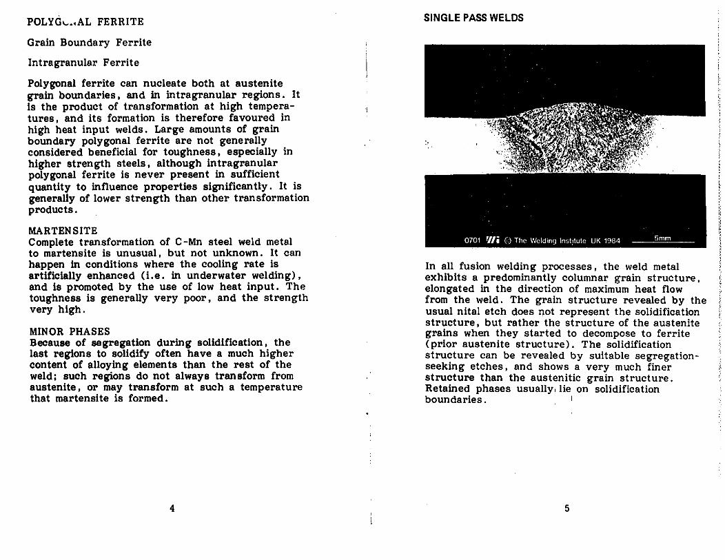
In all fusion welding processes. the weld metalexhibits a predominantly columnar grain structure.elongated in the direction of maximum heat flowfrom the weld. The grain structure revealed by theusual nltal etch does not represent the solidificationstructure, but rather the structure of the austenitegrains when they started to decompose to ferrite(prior austenite structure). The solidificationstructure can be revealed by suitable segregatlonseeking etches, and shows a very much finerstructure than the austenitic grain structure.Retained phases usually, lie on solidificationboundaries. I
5
,.i>
t>;:,>'>,'>~;:),,,I~,)'i
f:
~"

The micrographs above and on the next page showacicular ferrite. AF and grain boundary ferrite GF.Note the interlocking appearance of the acicularferrite. its low aspect ratio. and the fairly clearlydefined orientations along which the laths lie. Theamount of grain boundary ferrite can varyconsiderably.
6
7
/-
"0._... _,-- 1"'"'\

, .
,,
'. ,
,•
' •• J. " ..
.'
"
'-
• " j
,
,
.;...~ ....
". ... ,.;' -,
.... '
,
.,'
0706 'IIi ©' The Welding Institute UK 1984~
...'l
•
t'_ • ...
Rl:l AINED MARTENSITE P~H I I,v:, I t.1\l1 "
':,'/:<.'': \;~~., ,. , .J .. _ • •
. ~ ...... ,. ....- "'-""~.. " i
.::'~'~>...~(~:; ~;;OJ:.: C,,':.'... f' (;~.. :~.,...;.
.. 'f' ~ . . t'\. • t /
)' ,. ..•• p •••• ; .... 1", ••~... ,:~," -... \. --. .
.,'
FERRI. _ WITH ALIGNED M·A·C
The micrographs above and below show typicalexamples of ferrite with aligned M-A-C AC. Theappearance of this phase can vary SUbstantially asshown in these two examples.
The presence of 'retained' phases (austenite andmartensite) is revealed using a picral (5% picricacid in ethyl alcohol) etch. The volume fractionof these phases can be quite substantial, but theyare often difficult to detect if conven tional nitaletches are used.
!;(
~
8 9
HIGH HEAT INPUT WELDS
. , -- ,". '.... ....:. -"'~)"J' ~~'.l "l;:"'" :':\~,' .~ ""-.'. , \. ~/·. . :,,'·:-·l·il ~ .. ,.~~, ~ .•" ':" ~ '~.< .~•. , ~.;. . ..• '4'''/ " 1;~,., •.~ "J~.r ." ,.; ~ J. .f"" -,'" ~:j.-'" ... \~. y -,.,1'_ ..':. ... .• ,~ ~..,. ". 40 '. ~,... '" '" ~'-:~i"~ _ ~~ ;." :l,l,~..... "~.~:.,).) -;'\,.'-. v.... .C~· P, .........-~·;N':>'i'~ ·~~:'-h'".~••~ '\\;''':~''i''<'~'''''!l\ t'S!;"1·. ":~'''''.''),),\.~~~ ,'-. '.,~, ~ .t~.. '., \ .', X.\" ".*",. . ~ _..,.., •• ,.·:";~I~- '1:-. \11' "f~ \,;:O:;J~ ••\V~::;.·j~'··'~~''''''M~_~~~-,,-_,<'.·r It V" ...~.<~4,:~.'. .,'.1\' GF ...·'y .."l2..·:t~..::,'~ :!;..... , --c~·,· ~;\~,/~, t .' ... )c\r"~!.I.· ,ti~ ..: I
. \.f~'" ~ :'J4~. ,;.\ ~ ":'. ""~ ." ~."'..t ..."" J~. .. I...... ;-,,, ~~~~ 1; . ,I ~r~-. ,..~~ " 'I- \.''N .~;o.' ,. .....
:rf~, ..~~~YJ ...*·, \~~;~;~:~~ \i,.....~~:~.J....' '~~l:;.-~ ~~ . ~.~..:.}'\. '-~i'''it{<.t,~'f~~... ~>:~t, .rI~ "~~.~~f,,··,l.';r~' ~ ~ (.~'-tit;!~r;l,¢·.~>.rW..(.~t.;,,·'~1-~ F~~~Vl:,,~').I.I '.'"fL~' ~~>t~< l.'"+ii.l~., ·..··~,I "" ~+''''' N ... ·$, AF •. I."",~ 'Ca'''''':;m.:~...! ... ,iI : .::;;"~ '1< "'';'7'''':: . . : .... ~ .4fF·.J'.:;. '.\\
;:.,< ~.~.~.~;;;{.~-.., ...-"~~i.l }"":"'J<4'.I"ll~ "-:"t . ~{.".t~.~ .. ~......... • ~~":"'''s.- ~"""":'-~".,~.'.. ~""I''''' } . ,~~J' " ')1 '. ''111== . - .. ~,,;: '.M>" I . ; '~'J'\ +0••. ~... ' ...... -,' - '~:'_4:S: '~"' •.-. '."t~.~ ". :...
• I' "1".""- ~...~.-.,'~• ...:......!!···..:y~··L x,~ f, ;......... .s ~ .··.··8 . ;"i.,1 '.' ...,
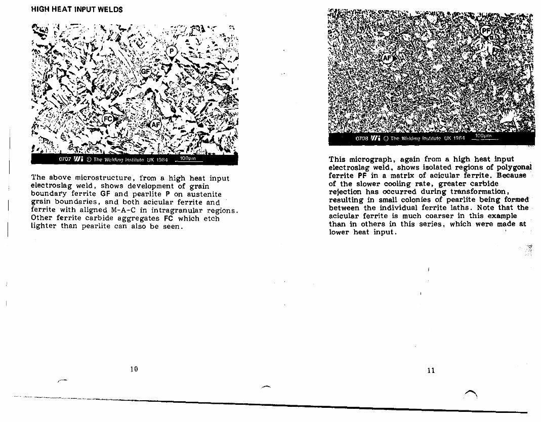
The above microstructure. from a high heat inputelectroslag weld. shows development of grainboundary ferrite GF and pearlite P on austenitegrain boundaries, and both acicular ferrite andferrite with aligned M-A-C in intragranular regions,Other ferrite carbide aggregates Fe which etchlighter than pearlite can also be seen ..
10
,-.-
This micrograph. again from a high heat Inputelectroslag weld. shows isolated regions of polygonalferrite PF in a matrix of acicular ferrite. Becauseof the slower cooling rate. greater carbiderejection has occurred during transformation.resulting in small colonies of pearlite being formedbetween the Individual ferrite laths. Note that theacicular ferrite is much coarser in this examplethan in others in this series. which were made atlower heat input.
11
.... _."'-" .....- .... - ..- ."'"'\

12
HEAT TREATMENT
Conventional post-weld normalising does not givesuch a fine microstructure as normalising bysUbsequent welding, as the thermal cycle is muchlonger. This microstructure, from a thick sectionplate, shows a typical ferrite F pearlite P structure.The pearlite regions are generally associated withthe solidification boundaries, more noticeably inhigh heat input welds where initial segregation isprobably greater. Stress relief by heat treatment isnot readily visible·in the microstructure. It can leadto transformation of retained phases. precipitationof carbides etc .• and spheroidisation of pearlitein high heat input welds.
13
....-.- .. ~- ,

Weld metal which has been reheated above AC 3 bya SUbsequent weld pass has a rapid therme.l cycle.resulting in a very fine ferritic transformationstructure. Such a microstructure is normallyassociated with very good toughness,
15
~'~ .-~. '... -~.. '-.' ,.... :"t.' . -r"I..- .;. ...it": ~.: '~'. , ...r'....,;;;~ .•~-""'~. ~ ... , \.•. !o'<!.,,:-. h~~'... . 4~;t..Il;y;....;K.-e.t,,._~'." "':~~A:t' <l.;;J~
~"'~r·:-'-· !~. " ~C.\. _'" ".~""."" 7:"-: or,. .' '. ". -'''f'#.' ,~'$.("."'~ol;··;)~.,\;t;.W.,~~·:~~~~r;,~:.~~?~.'~)t·.':!'·'?"'~,~~.·"~'.':'~~I:~"f':l.:~t.i'." ._~~,.<,... ,W r " r~' " • .'" ,"" '~:.Iij' '. "';4. _ " •.. ~''' '" <~..... ''!,,) 'It: ~.r ;:,". ·_l~·-:........ \, ..\",,; :>' .. r".l'''''1"':' ~,. " ~ ." . . "';fI' \ '. "'f". t·"·",,, ' .,...~.,~'~:1f<{ .~. )H~!t:~I~r;';~.~[~l'~i''';.''!<'.!Fi:F.:/~.'I"'j,"",'I~~.cr ).'~~.....i"':J1··~.~ ·_/)..·· 10".... ..,~ ..... ,\" ... ~··;.,T.41" M 'O"'-"'J '~'l:-'" .I'..l • ~l~ ':"'\'.~:'/(':-'-".' '~\' ~~ "'/':t~. (,.:P~:";"\.~~r \t !.~·l't~~A.,,~ ~~ ,,,{.,. .', .....::/~r~. ,'t (,,0.'
., <"",·1 C',..l'_" " ,,,I<-J> 's" '" .<,., ,,-." ''v?'' , . • .':)~ "~...,{~..,~ ~.' .. ;. !"lll;~~d'~ ";~.' ;"~i..2!':~.'" \ l-", ":.!' ;.:!::: '~:"""'" ":··'.J.tC\'~"'~''''''... ....;~~..,;.:.... 'SJ ~'-.J ..~, 'Q.~l: "" ~e:t~./" ", , ':--:'" ''';;;:''Jl.of, ." ..• ~••~'"';;...:.
:{~"::~~~;lfIJ,~FJ;~_t.::.~~E-~."tti;t-,y~·~}t...sL~';;~\:;,:~'. ~ "~,,. "-";';-h~@';" ·:l"'~· .,!,,,;,~~ ~ "'-'i!~" '~~".-¥.' .J .."" ..r',:, ... ~ .::~..;-o;r'~·,.'>V:.... J .... :4l'·~.~ ,.t·.:f';~.f1·"\:~I.'-~I"1 . . :,t~ .. ;:.C1'\;;' . :' ;- •,~>,.{t .:>~.~""'"'..!>'.~.,,,;I .~:r.".' -I-,""?H~" """-..~:. ""'Ji~\~~,.. J'(-,.,.. ~!i"'"'~:l.;, "';'?" )1'1" .• '~"'I>i;'t· ",g'~.- ,,.;:>o;,,.:'It" '. ":I." :\~~... :..« . f~r~:-"~' ~. ".:,'" ,l>"';~ >,:::;r..e;:'~,,- ...')oo....~_: --:<.'! r'"d;,
"\,It~;~'.r.~, -,~·~~,:tf~H/'~4~";'1-,'" '~"':<,,<.,.Z!~,l¢ 't:t,s·. 'Y.tl.,::.....-t. . .:. .'~' .N");~!:· .... I ....~ r-o_':.o\: . /.~ t\- 4 .......~1~r:"1\t .. ". ..~: ·~.fl~· i:~)}$ ''::' ~..~!{t:t~ :.:.~y~ .. J~'~~ ,~·~~'..;.<(;·..: .. r.~e·
14
Where a joint is welded in more than one run. themicrostructure of the early runs can be completelyaltered by the heat from SUbsequent passes. Wherethe temperature rises above a critical value (Ac 3 )
in the region of 875cC. then complete transformation to austenite will occur. which results in arefined structure which is essentially similar to anormalised structure, i.e. containing only equiaxedferrite and carbides. As the thermal gradients dueto successive passes are steep. the microstructuresin reheated regions can vary considerably overshort distances.
~.
----.-.._... ~

HEAT I-\t'FECTED ZONE
The thermal cycle at any point in the HAZ is highlydependent on the heat input and the distance fromthe fusion boundary. As this distance increases, thepeak temperature and cooling rate through the trans-
16
1I
formation range are reducetl. giving progressivelysofter microstructures. This is shown above, whichillustrates the whole heat affected zone, startingwith the fusion boundary on the left.
17

A view at higher magnification of part of the heataffected zone shown in slide 0712, near the fusionboundary. heated to a temperature sufficient topermit rapid austenite grain growth, typicallyabove 1000oC.
18
~
A view at higher magnification of part of the hea~affected zone shown in slide 0712, towards thefusion boundary, but farther from it than slideheated to a temperature above Ac 3 • but insufficientto produce rapid austenite grain growth.
19
,...""""",

INTERCRITICAL HAZ
A view at higher magnification of part of the heataffected zone shown in slide 0712. towards theparent metal. but farther from it than the nextpicture. heated to a temperature between Ac 1 andAC3' resulting in only partial transformation toaustenite. SUbstantial refinement occurs.
20
SUBCRITICAL HAZ
A view at higher magnification of part of the heataffected zone shown in slide 0712. near the parentmetal. maximum temperature less than Ac l' Pearlitemay be spheroidised.
21

22
MARTENSITEAlthough this constituent M is promoted byincreased alloy content, it can also be found incommon C-Mn steels welded at low heat input. Itis hard, usually of poor toughness. and can giverise to HA Z hydrogen cracking. Complete transformation to martensite is unusual in the HAZs ofC-Mn steels. and only occurs when cooling is veryrapid.
FERRITE WITH MARTENSITE/AUSTENITE/CARBIDES (M-A-C)This is generally the predominant microstructuralconstituent ,in C-Mn steels, occurring over a widerange of heat, inputs. The illustrations show thatferrite with M-A-C can have an aligned AC ornon-aligned FN appearance, but this variation isprobably largely a sectioning effect.
INTRAGRANULAR WIDMANSTATTEN FERRITEIntragranular Widmanstatten ferrite WF may beformed with high heat input. It cari be distinguishedfrom ferrite with M-A-C by the small aspect ratioof the ferrite laths, and the characteristic basketweave type of structure. It resembles acicularferrite commonly found in weld metal. Intragran~r
Widmanstatten ferrite forms at higher transformation temperatures, and is favoured by the slowercoollng ra,tes associated with high heat input.
PRO-EUTECTOID FERRITE I
This constituent FP is often formed on prioraustenite grain boundaries, esp'ecially with high:.!:heat input. Its formation is suppressed by aIloyihgelements Which lower the austenite decomposition,temperature.
Continued~f
23
.."
,..,",
....•.....~._----------

This con .uent P is associated with very highheat input, such as in electroslag welding, and issuppressed by alloying elements which depress theaustenite decomposition temperature. It is generallyfound only in association with pro-eutectoid ferrite.
FERRlTE-CARB IDE AGGREGATESThis phase Fe appears in regions away from prioraustenite boundaries, and is the result of theeutectoid decomposition reaction. At very highmagnifications. It appears as a dispersion ofcarbides in ferrite.
24
I Yt'I~AL MIl;HUSI HUt; I UH!:S 11'\1 HtA I Al-fl: ';U
ZONES
Slides 0712-0716 show one HAZ with a limitedrange of cooling rates; the following six photographs, slides 0717-0722, illustrate a wide rangeof HAZ microstructures arranged in order ofcooling rate, starting with the most rapid.
Most rapid cooling - low heat input
071707180719072007210722
Least rapid cooling - highest heat input
25
:;
t::~t:
IifJ
"'I
t:Ii~!
Ill,:j';"t~,,'i;",>.¥~ft~,~I·;,i:j~.
~,'..'".;~(;

In this exampll'!, transformation to martensite isvirtual1y complete.
26
'.. . ~~\ c ; /$'
.~''- ..\.' .
. .,.f. '",
"
The ferrite with aligned M-A-C, AC. is nucleatedprimarily at prior austenite grain boundaries.Martensite M is also present.
27
")-,-~,._._-. ".-~-.~-- <--'''''''''."""",---"

~ I '.' , • • ....
.. ,",' ,., .. ~, ~ .'~":~~':: (I'.' .~:... :~~. :,::" t9 . "/~:.\t. " '... ",' . . . ""'.' ., .. , ~. , " I. ''. \. . c.. . ". ._ ;'j .' '. ,of.,: • ' • ....,•• '••
.... \ ,,\,: l'>.1'l' ... ·./.4' '._i, ,I! I.I ..~,:;.. ""\' AC .. :"-..,:...,:/"."'\ ...., l "",:.''''~~.~.:i~\··f,. ~\:" __ ', ~~ .. . J.' :. ..~.••f,:" : ::..,11":"\ .. ,~::, ;'·.~'::J·:·?:\~?(~~S'~!;.~~\,\.\t ".~' '::":"'!(':2'·. :..:. ~.:: ,~,,~ ': f~>,::.;
~ .' ....~~ .....~~~"~.,,.,',..~~,~;..~\~9.:.::. f .{ .. ~ ~ •. ~:-'.,' ,., ..... ,. ,_,,, ~.,) ••,_.~,'" '," .;'..-: ·,::-J.·~~~,,\,"tj:.~}·"~'::~~~~:; ~'~~r:'!, '."~ .<r·:.··,::i, ..~~:f·;.!.(,~ ••••••••• , 0.. ~·"'~·,fIl'\..\.\ .....,·,~.~·}., . ..-:.,·~".'J" ·.IJ ....~~:~\ '1· I ..... /' .~~.. ,.:.~
'" ....... .,. ,~ , \', 't': • ".,. ,-_",...of: .... M ·~t.. '.. ).... .... -., .....\\.\.\..~ ......}.,.\ .~I.: .. \ l,.~~,;~~~\'\»'~.•r. '.~'"-''' "'" Y··~!'r.~·••} l·.....·<I.· Jt•• ...;-..,
.•. ~'~. ~, :"p~:-~ '" r " '\\ ~,...,\~··ft·\:,~r "1 1 \..:~\ 'f'L::'r,t,~' .. ,\';~"'jfJ:./I "" .... ':I>. ~•..l:\·~.:·~:\\~~' \.~:;~i::'.: ~~~:i;.\tz~11~~~1-I',~};.~~::;~7;~ .~~~·l·~/y '0~:?l,::··~ ~~:;.,:"M ," •• ~ ( • \,. " ~• ...... i /.It:l~1 . oJ.,£,· ~I ".;; .J ... .,. ... ~... ....... I. \; 1.(' .~.'.._{.;,,,,: .._~ \\\...~/:. .....t:~~~\i':'e.'~ .. t:.' .... ~l::" •• :{..ll·~;'1o£:,t,,,,,· ~ :~'\"'.:.''''''-';' ..., :.~":a....:.:;.1.J~~.~\. \. :<<':"~ I..: ..,·\f~~..~l;~~;;~ 'l't::;f~ ._~~:-~.~~':~1.~'~\''':::::' ... '/ <. ,"-,._.?t.¥.Z.~~:~~:{~~~~~\·>:~~~:):1~1~~1~1~~I#)~·~~~~\;~~~~:·:o~ •.,." ...~_......,q. ~":~"'.'.~':."lt.. ::~ l~;,," .", ......~V.~l-_ ~':o~~i"i:--: •• C,.r:.1.t.. ~,:.:..~~;....";" ..:.l)t;O:;·iUf"\,·.~ .,''"':'':..... :~ ..... '·'';'j.\P~'l''·~:'''''::;}'~'';ir,...'';u''''··'~ ..··IJ.~I:--:~~~~'•"f··;,.f:;· ·..~.l!. ~ tv,"';' .~;t': tv,:.:\1..f~:-: ii::.... !~~::: ..~~-;~:t "'Il'" ~,.e-,.IIo,~" t ..~.:..~,~.~;.:.o:...,: ~"'_Jf2:.7:'..:c\\" ....-t ,I' .. :., ~.~~~/... "'\t..:..,,,~.t"~(1"'''' ..''l' 1 .. """ .,t~' ..\:..?-""",~\ ~.t'~..4.-;j,n '-:-:~~(i" ,".l ~t:',-~j';"~1': \. • :l~lf.r."""#"'" ~;:'-',,: ~~(•• ~\ :1.::;).., ~~ \'~)")."f:~".. "J"""l~j ~~r~ 1-' ;!'l··~.t· ~"'~ .-.' FN ,1)1,f'i.........:,Io;!..!.,::.~i7·, !tt,' ~.!t\\, · ~v ,'~v:~~\.\ ~..oS,';,\ "/1."" "'l'" ~,1';J' ...~~ "" J. ~.·.lli'i·._ ... r •.r<l'.~/;I-, .. ,; .... :'.: .... ,,'ltc'.. ,:,,#~~ .,:. ..{ ~:,,·... t·,;.-=: 'C, ••)~f.:. r·r.'.::·~";$ ·~:wl,l...2·'~«i 'ti 1~ ..~.,·;,·"tl·••l:>;l,..... -~...·,;·~,..·: ... 11t, ..·-~·, ~t .... ,'.,""'\~·-:~·· ...~ ~ •.. ; j'• •••" .. '.~~~ll,.\v. .......;....,;,J-....·t .. ;,. ':Of ,....:.~.:-.t':':·pS'~:.J:.~1r.• !r .~!-'''~'.~!,1'Ii ~'... Z~. ,:/'f: .-J; .\ .~/.1.",:"'.I"~
Fine ferrite with M-A-C. showing aligned AC andnon-aligned FN modes. In this example. grainboundary ferrite is suppressed.
28
Coarser ferrite with M-A-C than in slide o?;sinpresent in both modes. aligned AC and n<aligned FN.
29
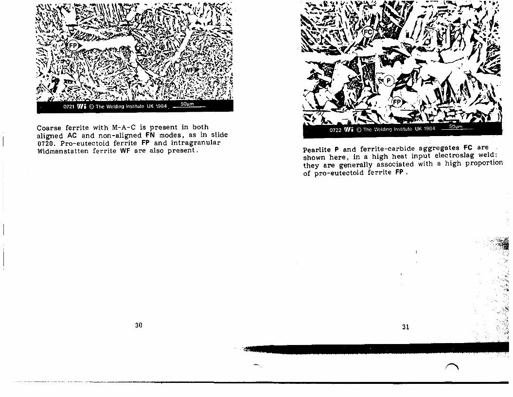
Coarse ferrite with M-A-C is present in bothaligned AC and non -aligned FN modes. as in slide0720. Pro-eutectoid ferrite FP and intragranularWidmanstatten ferrite WF are also present. Pearlite P and ferrite-carbide aggregates FC are
shown here. in a high heat input electroslag weld:they are generally associated with a high proportionof pro-eutectoid ferrite FP .
30 31
,'.J>',
/'""'1
'.,., ....".'''' ..,._~.,._---.,----------------------------
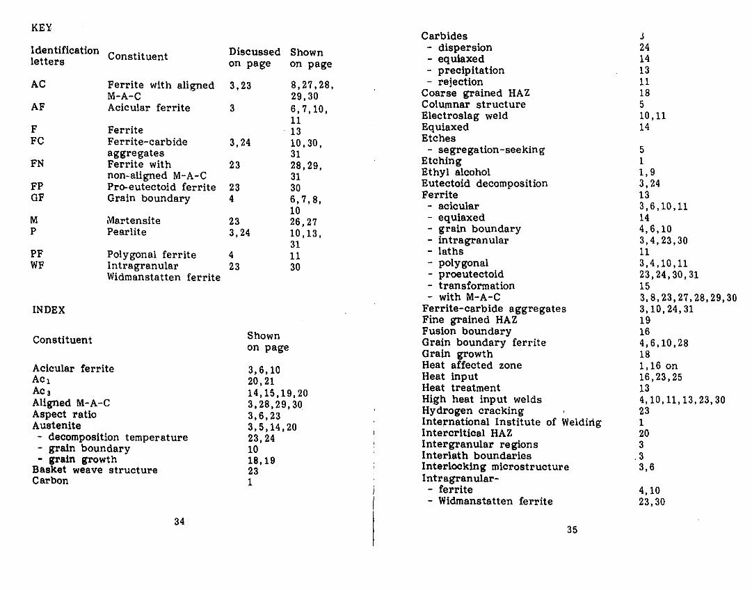
KEYCarbides J
Identification . Discussed Shown - dispersion 24letters Constituent on page on page - equiaxed 14
- precipitation 13AC Ferrite with aligned 3,23 8,27,28, - rejection 11
M-A-C 29,30 Coarse grained HAZ 18AF Acicular ferrite 3 6,7,10, Columnar structure 5
11 Electroslag weld 10,11F Ferrite 13 Equiaxed 14FC Ferrite-carbide 3,24 10,30, Etches
aggregates 31 - segregation-seeking 5FN Ferrite with 23 28,29, Etching 1
non-aligned M-A-C 31 Ethyl alcohol 1,9FP Pro-eutectoid ferrite 23 30 Eutectoid decomposition 3,24GF Grain boundary 4 6,7,8, Ferrite 13
10 - acicular 3,6,10,11M Martensite 23 26,27 - equiaxed 14P Pearlite 3,24 10,13, - grain boundary 4,6,10
31 - intragranular 3,4,23,30PF Polygonal ferrite 4 11 - laths 11WF Intragranular 23 30 - polygonal 3,4,10,11
Widmanstatten ferrite - proeutectoid 23,24,30,31- transformation 15- with M-A-C 3,8,23,27,28,29,30
INDEX Ferrite-carbide aggregates 3,10,24,31Fine grained HAZ 19
Constituent Shown Fusion boundary 16on page Grain boundary ferrite 4,6,10,28
Grain growth 18Acicular ferrite 3,6,10 Heat affected zone 1,16 onACl 20,21 Heat input 16,23,25AC3 14,15,19,20 Heat treatment 13Aligned M-A-C 3,28,29,30 High heat input welds 4,10,11,13,23,30Aspect ratio 3,6,23 Hydrogen cracking 23Austenite 3,5,14,20 International Institute of Weldirlg 1- decomposition temperature 23,24 Intercritical HAZ 20- grain boundary 10 Intergranular regions 3- grain growth 18,19 Interlath boundaries .3
Basket weave structure 23 Interlocking microstructure 3,6Carbon 1 Intragranular-
- ferrite 4,10- Widmanstatten ferrite 23,30
3435

.u .....··6.....·· ... _ ...MartensiteMinor phasesMUltipass weldsNitalNitric acidNon-aligned M-A-CNormalisingPearlite
- spheroidisationPicralPicric acidpolishingpolygonal ferritePrior austenitePro-eutectoid ferriteReheated regionsRefinementRetained phases
- austenite- martensite- transformation
SectioningSegregationSingle pass weldsSolidification boundariesSpheroidisationStrengthStress reilefSubcritical HAZSupercritical HAZThermal cycleThermal gradientThick sectionToughnessTransformationUnderwater weldingWidmanstatten ferrite
3,4,23,26,274141,5,9128,29,30133,10,11,13,24,3113,219913,4,115,23,2723,24,30,3114205,9,13991311355,1313,211132118,191,13,15,1614131,15,2314,15,20,26423,30
~·,l
";.iI!
'::ii··;;S.. "'~
,;(:,'. ~"""
",""
,j;'"
36
A
·.···..t··;
. . 's·'"
-_.__ ..~... _...•..._--.__.._----------------......,..------


