This is the manual for Meter is the program to make scales for analog metermovements.
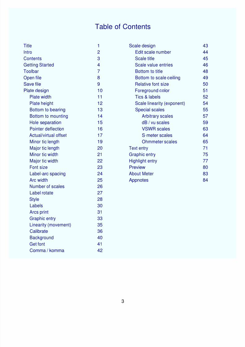
After a short How To Start section, the manual is intended to be for referencepurposes. The items listed in the Table of Contents will illustrate how to do various tasks. It is arranged in a logical manner but is not a "how to" document with theexception of the AppNotes section.
This is the first printing of this manual. Surely there will be areas that should beupgraded, corrected or changed and we will most certainly welcome comments andsuggestions. E-mail us at [email protected] and we will respond assoon as possible.
Meter is a Windows program from Tonne Software. As downloaded it is wrapped intoan executable install package with a filename of MeterInstallxxx.exe, where xxx
is the revision number.
After that executable has been downloaded onto your computer, run it to perform theinstallation. If this is an upgrade then run it and answer Yes to the question aboutunloading the old version. If upgrading, your designs should remain intact unless theyhave the same name as one of those in the install package; the installation willoverwrite those files that have the same name as any in that package. It will not overwrite the user's designs if they have unique names.
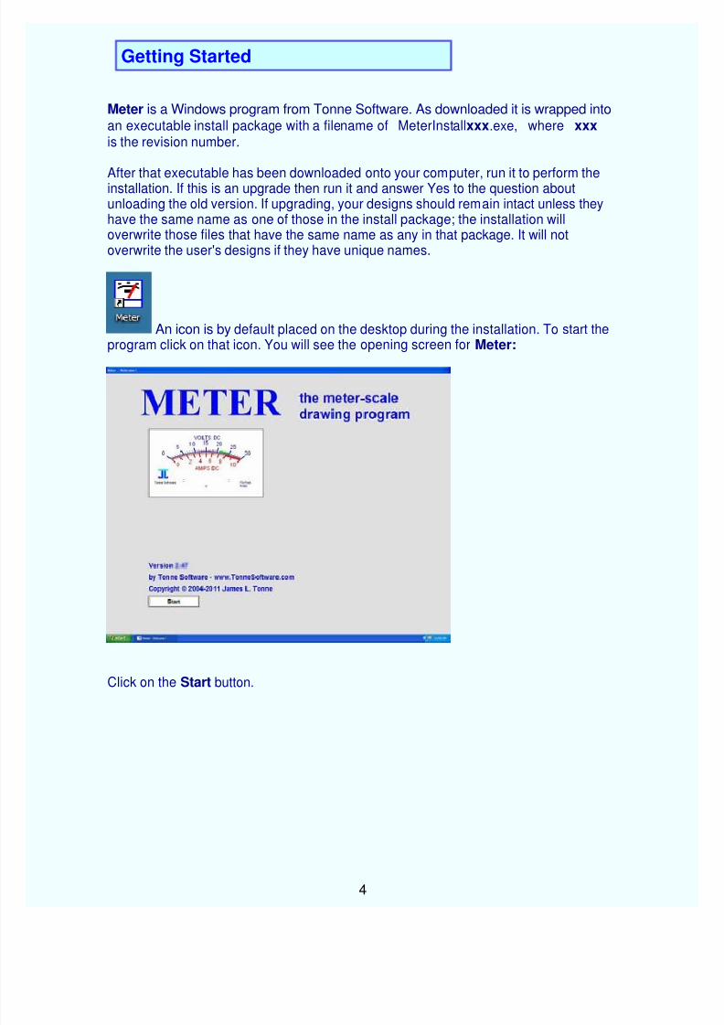
An icon is by default placed on the desktop during the installation. To start theprogram click on that icon. You will see the opening screen for Meter:
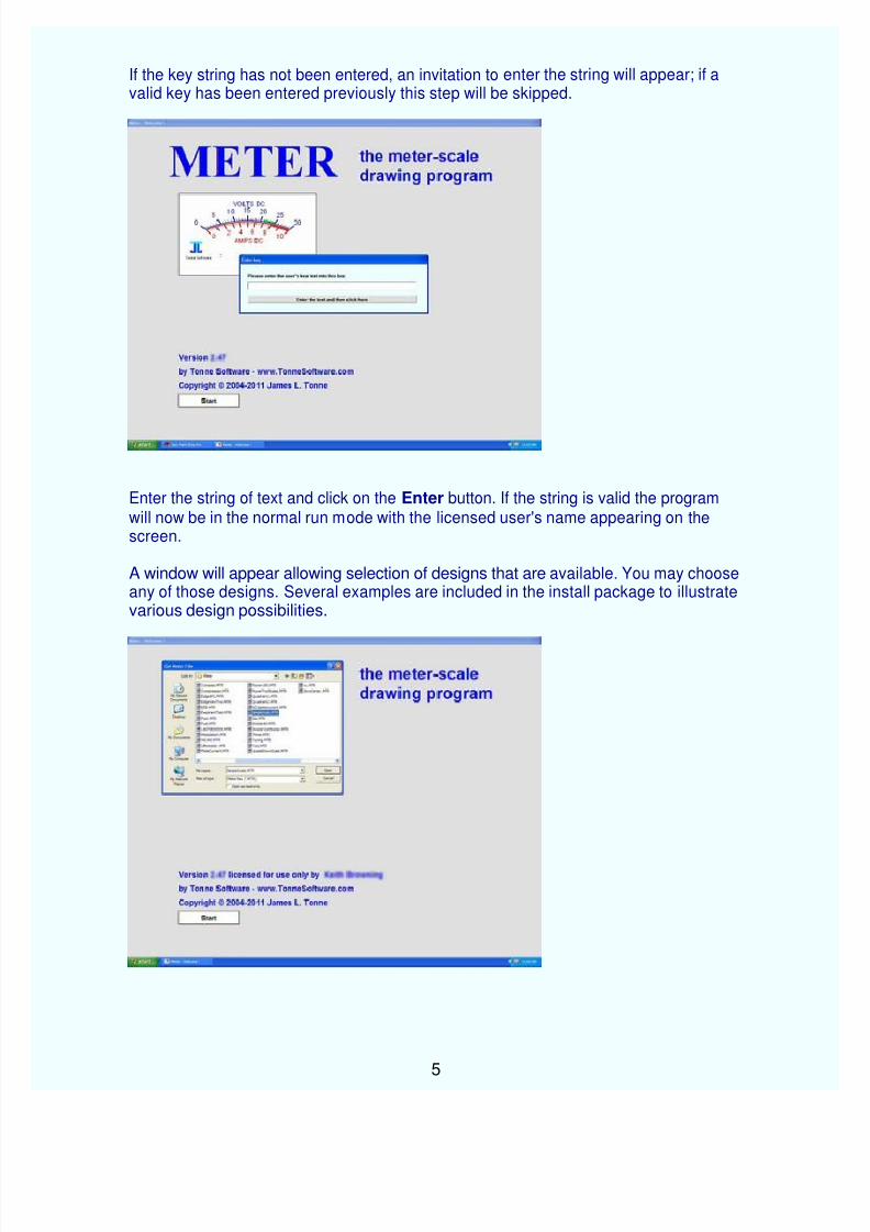
If the key string has not been entered, an invitation to enter the string will appear; if avalid key has been entered previously this step will be skipped.
Enter the string of text and click on the Enter button. If the string is valid the programwill now be in the normal run mode with the licensed user's name appearing on thescreen.
A window will appear allowing selection of designs that are available. You may chooseany of those designs. Several examples are included in the install package to illustrate various design possibilities.
For this writeup we chose "SimpleScale." As soon as the selection was made thatdesign appeared on the screen as seen here:
Now we can exercise the various options in Meter to edit the design as desired. To dothat we need to take a look at the toolbar with its icons at the top of the screen.
At the top of each of the major pages in Meter is a toolbar with icons. Clicking on one of those icons will enable a particular action.
Here is the toolbar:
Beneath each icon is a word describing the action.
Clicking on that first button will take you to a routine to open or get a Meter file.
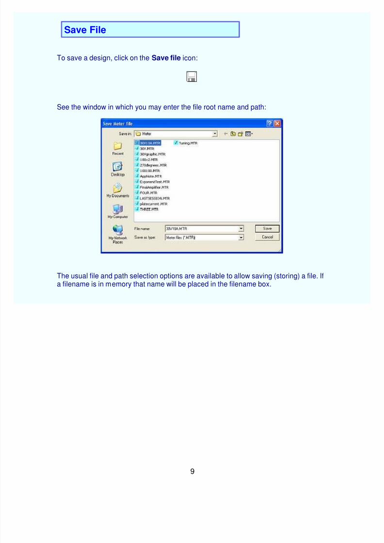
Clicking on that second button takes you to a routine to save a Meter file.
Clicking on this button takes you to the Plate design page.
Clicking on this button takes you to the Scales design page.
Clicking on this button takes you to the Text entry page.
Clicking on this button takes you to the Graphic entry page.
Clicking on this button takes you to the Highlights entry page.
Clicking on this button allows you to Preview the meter scale you have designed.
Clicking on this button allows you to Print the scale as designed.
Clicking on this button calls the Help system.
The exact page which is called is context-sensitive.
Clicking on this button allows you to Exit the program. The small screen called up also allows you to cancel this operation and return to
the program.
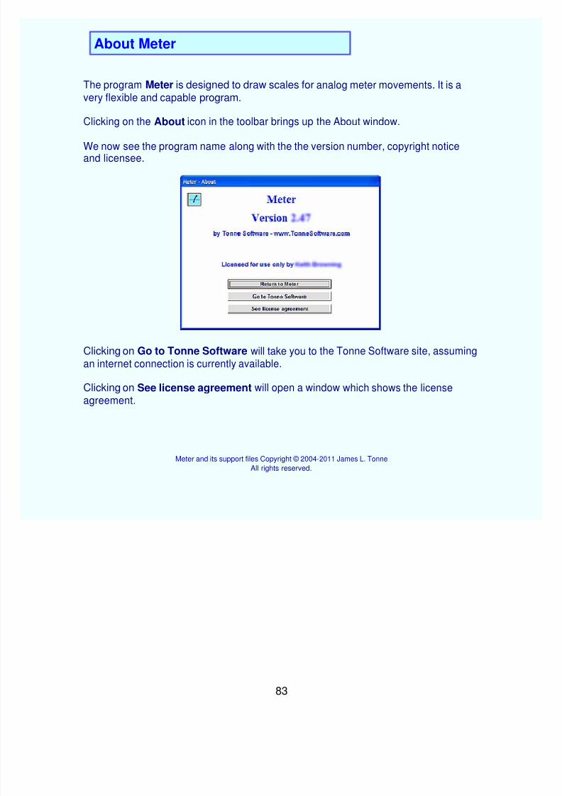
Clicking on this button allows you to look at the About page.
Now we are going to look more closely at those items. The Plate icondiscussion will be followed immediately by discussions of each of the optionson that page. Similarly, the Scale icon discussion will be followed immediatelyby discussions of each of the options on that page.
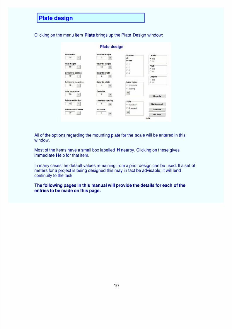
Clicking on the menu item Plate brings up the Plate Design window:
All of the options regarding the mounting plate for the scale will be entered in thiswindow.
Most of the items have a small box labelled H nearby. Clicking on these givesimmediate Help for that item.
In many cases the default values remaining from a prior design can be used. If a set ofmeters for a project is being designed this may in fact be advisable; it will lendcontinuity to the task.
The following pages in this manual will provide the details for each of the
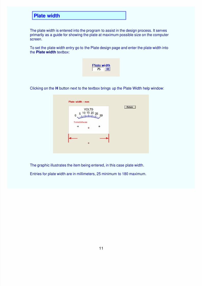
The plate width is entered into the program to assist in the design process. It servesprimarily as a guide for showing the plate at maximum possible size on the computer screen.
To set the plate width entry go to the Plate design page and enter the plate width intothe Plate width textbox:
Clicking on the H button next to the textbox brings up the Plate Width help window:
The graphic illustrates the item being entered, in this case plate width.
Entries for plate width are in millimeters, 25 minimum to 180 maximum.
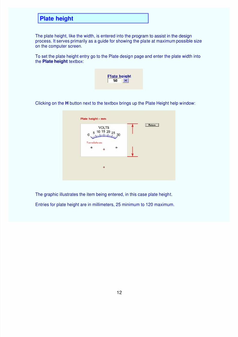
The plate height, like the width, is entered into the program to assist in the designprocess. It serves primarily as a guide for showing the plate at maximum possible sizeon the computer screen.
To set the plate height entry go to the Plate design page and enter the plate width intothe Plate height textbox:
Clicking on the H button next to the textbox brings up the Plate Height help window:
The graphic illustrates the item being entered, in this case plate height.
Entries for plate height are in millimeters, 25 minimum to 120 maximum.
To change the distance between the bottom of the plate and the pointer bearing, go tothe Plate design window and enter the new value in the Bottom to bearing textbox:
Clicking on the H button next to that box will bring up the Bottom to bearing helpwindow:
The graphic illustrates the item being entered, in this case the distance between platebottom and the bearing.
Entries for bottom to bearing are millimeters, -100mm minimum to +200mm maximum.
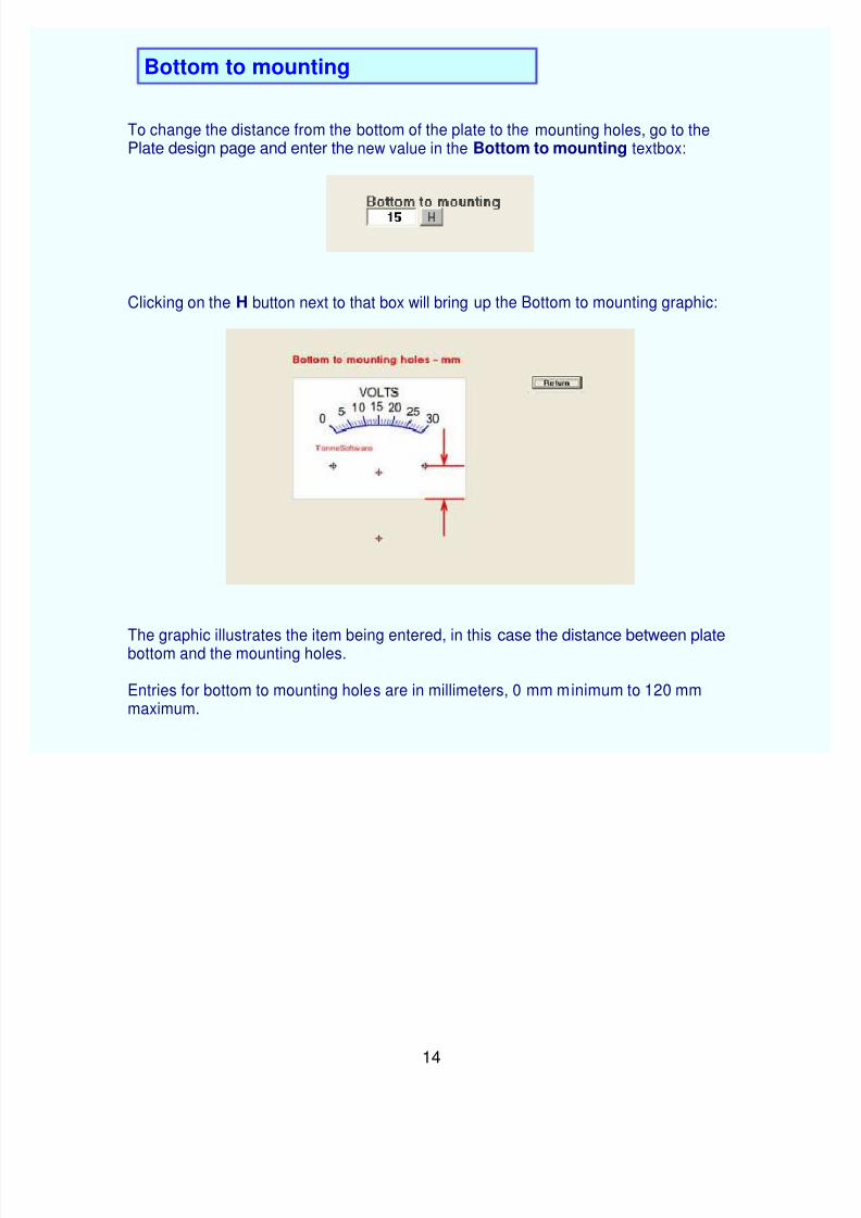
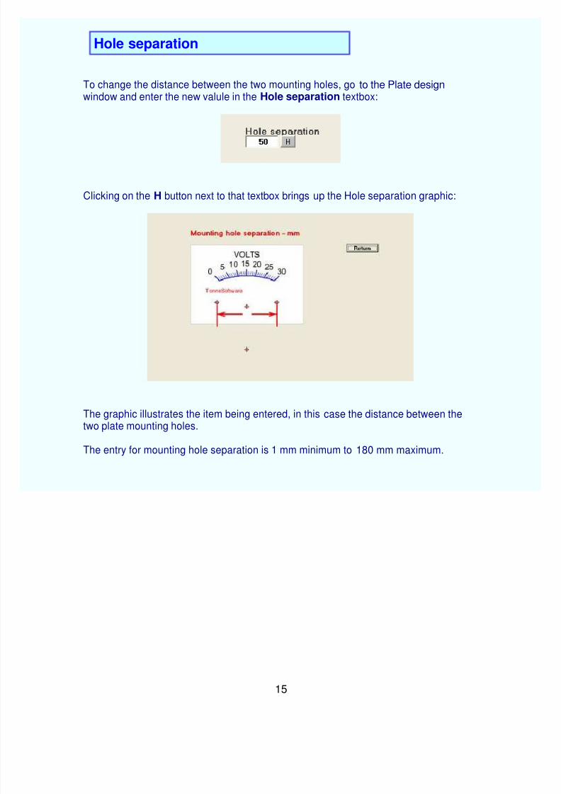
To change the distance from the bottom of the plate to the mounting holes, go to thePlate design page and enter the new value in the Bottom to mounting textbox:
Clicking on the H button next to that box will bring up the Bottom to mounting graphic:
The graphic illustrates the item being entered, in this case the distance between platebottom and the mounting holes.
Entries for bottom to mounting holes are in millimeters, 0 mm minimum to 120 mmmaximum.
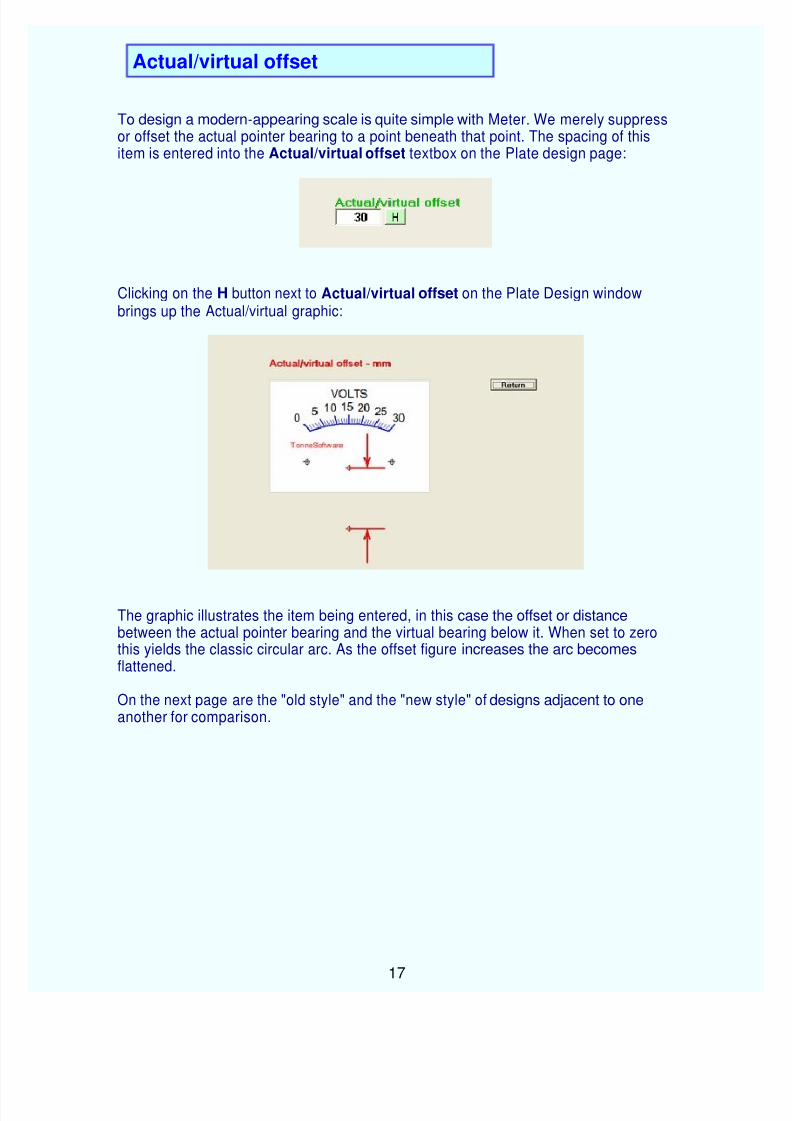
To design a modern-appearing scale is quite simple with Meter. We merely suppressor offset the actual pointer bearing to a point beneath that point. The spacing of this item is entered into the Actual/virtual offset textbox on the Plate design page:
Clicking on the H button next to Actual/virtual offset on the Plate Design windowbrings up the Actual/virtual graphic:
The graphic illustrates the item being entered, in this case the offset or distancebetween the actual pointer bearing and the virtual bearing below it. When set to zero this yields the classic circular arc. As the offset figure increases the arc becomesflattened.
On the next page are the "old style" and the "new style" of designs adjacent to oneanother for comparison.
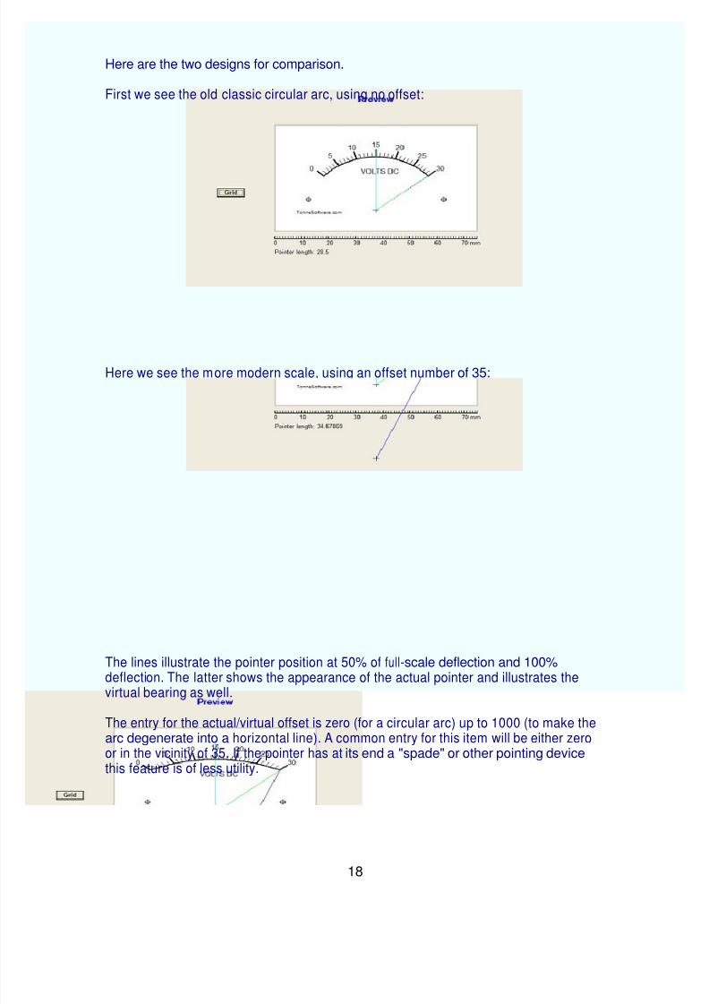
First we see the old classic circular arc, using no offset:
Here we see the more modern scale, using an offset number of 35:
The lines illustrate the pointer position at 50% of full-scale deflection and 100%deflection. The latter shows the appearance of the actual pointer and illustrates the virtual bearing as well.
The entry for the actual/virtual offset is zero (for a circular arc) up to 1000 (to make thearc degenerate into a horizontal line). A common entry for this item will be either zeroor in the vicinity of 35. If the pointer has at its end a "spade" or other pointing devicethis feature is of less utility.
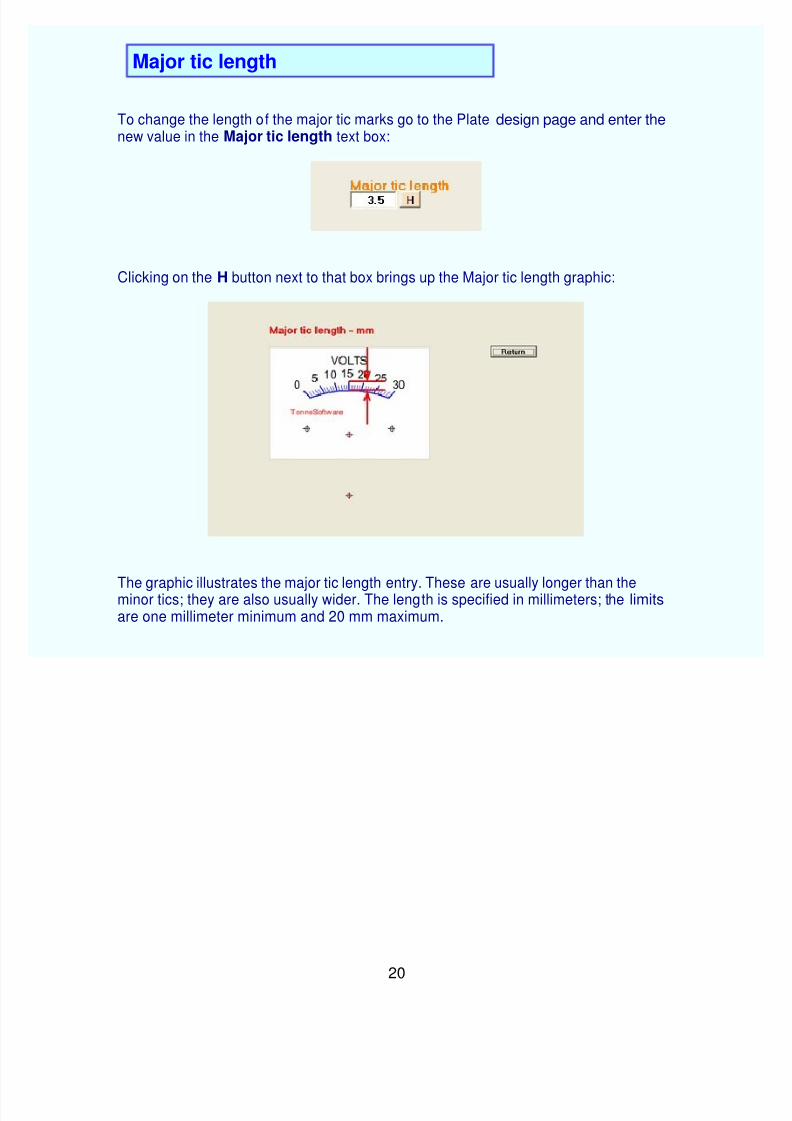
To change the length of the major tic marks go to the Plate design page and enter thenew value in the Major tic length text box:
Clicking on the H button next to that box brings up the Major tic length graphic:
The graphic illustrates the major tic length entry. These are usually longer than theminor tics; they are also usually wider. The length is specified in millimeters; the limitsare one millimeter minimum and 20 mm maximum.
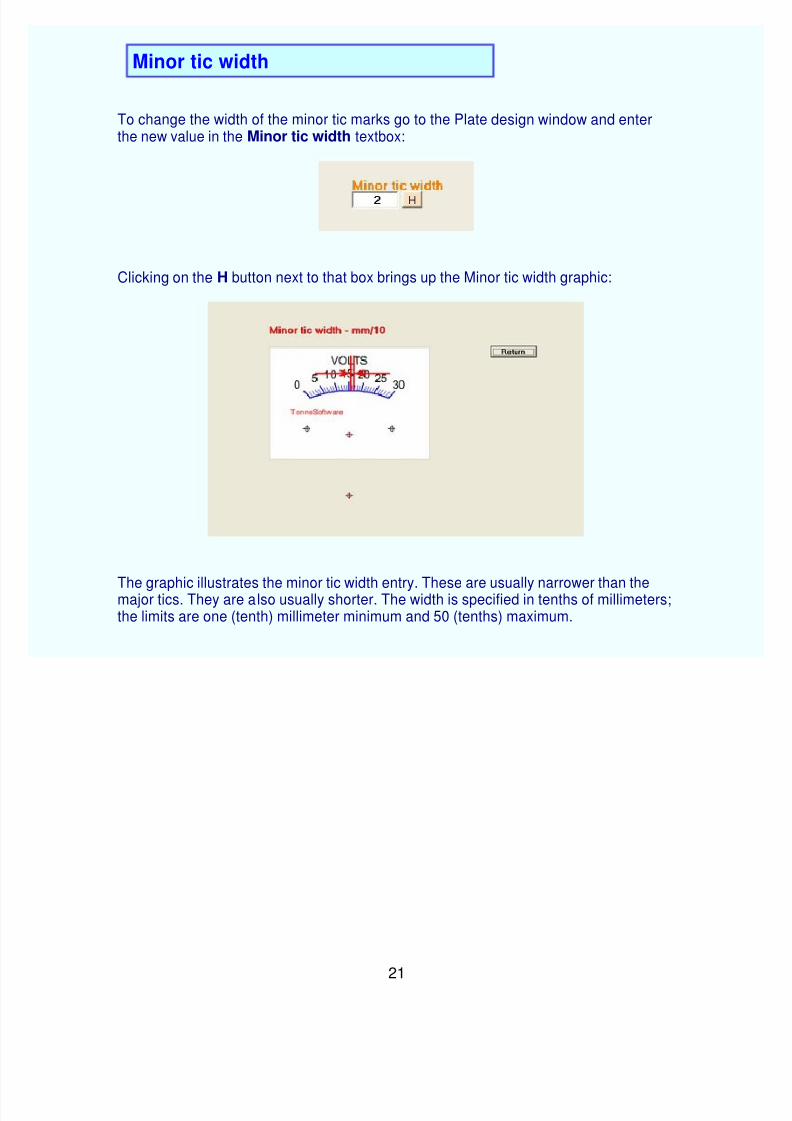
To change the width of the minor tic marks go to the Plate design window and enterthe new value in the Minor tic width textbox:
Clicking on the H button next to that box brings up the Minor tic width graphic:
The graphic illustrates the minor tic width entry. These are usually narrower than themajor tics. They are also usually shorter. The width is specified in tenths of millimeters;the limits are one (tenth) millimeter minimum and 50 (tenths) maximum.
To change the width of the major tic marks, go to the Plate design page and enter thenew value in the Major tic width textbox.
Clicking on the nearby H button brings up the Major tic width graphic:
The graphic illustrates the major tic width entry. These are usually wider than the minortics. They are also usually longer. The width is specified in tenths of millimeters; thelimits are one (tenth) millimeter minimum and 50 (tenths) maximum.
The size of the font is adjusted by going to the Plate design window and entering thedesired font size into the Font size textbox:
Clicking on the H button next to that textbox brings up the Font size graphic:
The graphic illustrates the font size entry. The program has been set to approximatelyagree with the fonts as printed using MS standards. A typical value is 6 to 8. The minimum is 2 and the maximum is 20.
The spacing between the arc and the labels for a given scale can be adjusted by goingto the Plate design window and entering the value in the Label-arc spacing textbox:
Clicking on the H button next to that box brings up the Label-arc graphic:
The graphic illustrates the spacing between the arc and the labels for the ticmarks. Atypical value is 6 to 8. Adjust this value so that the numbers are spaced slightly away from the ends of the major tics. The minimum is 0 and the maximum is 100. Thespacing for this measurement is from the arc to the vertical center of the text.
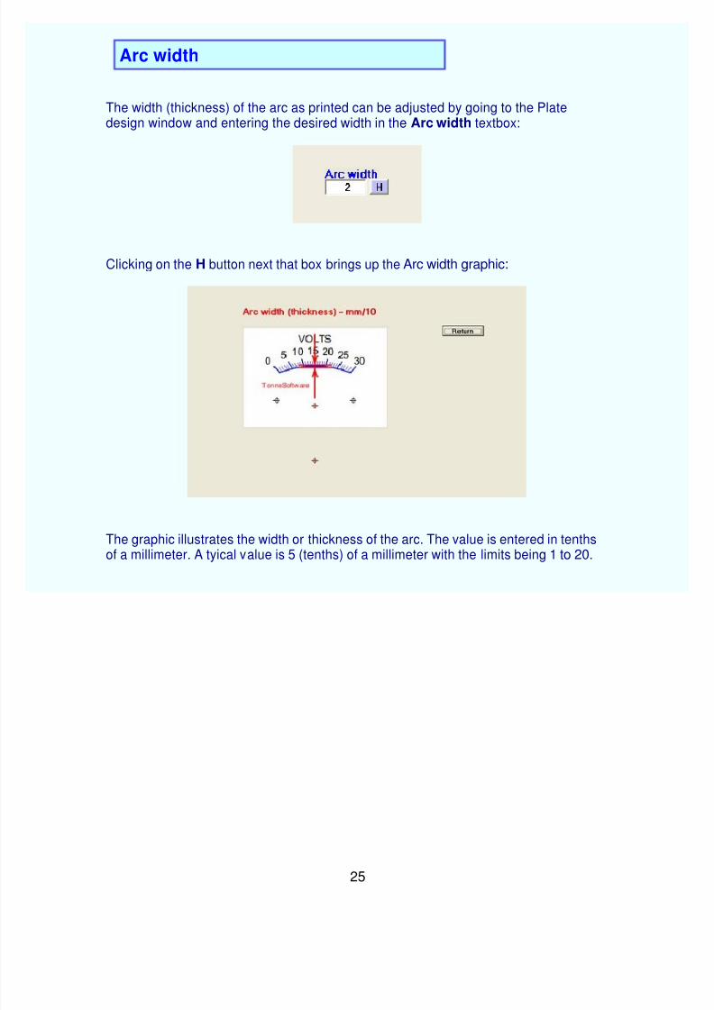
The width (thickness) of the arc as printed can be adjusted by going to the Platedesign window and entering the desired width in the Arc width textbox:
Clicking on the H button next that box brings up the Arc width graphic:
The graphic illustrates the width or thickness of the arc. The value is entered in tenthsof a millimeter. A tyical value is 5 (tenths) of a millimeter with the limits being 1 to 20.
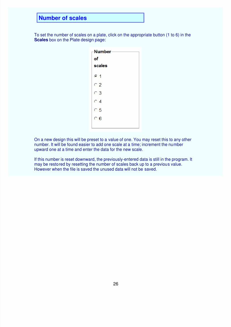
To set the number of scales on a plate, click on the appropriate button (1 to 6) in theScales box on the Plate design page:
On a new design this will be preset to a value of one. You may reset this to any othernumber. It will be found easier to add one scale at a time; increment the numberupward one at a time and enter the data for the new scale.
If this number is reset downward, the previously-entered data is still in the program. Itmay be restored by resetting the number of scales back up to a previous value. However when the file is saved the unused data will not be saved.
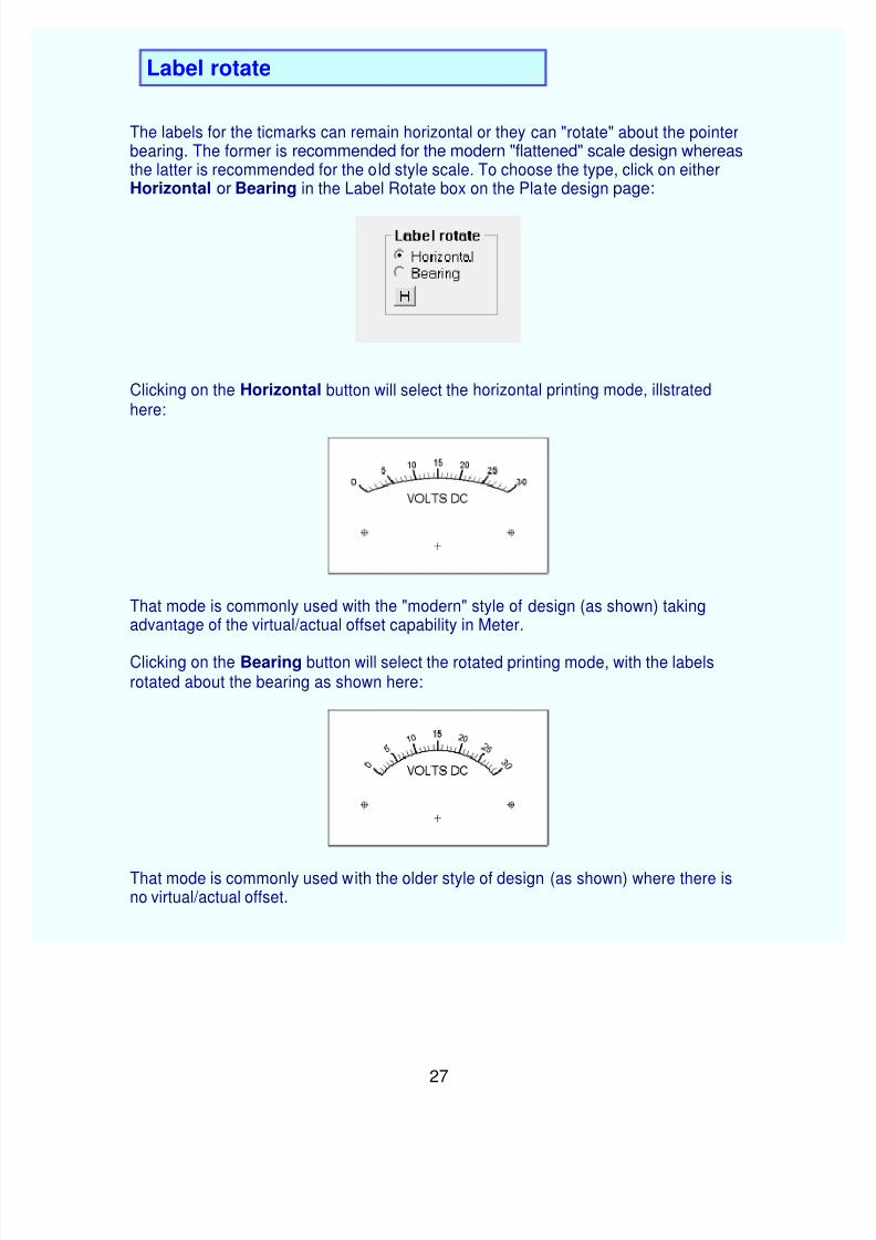
The labels for the ticmarks can remain horizontal or they can "rotate" about the pointerbearing. The former is recommended for the modern "flattened" scale design whereasthe latter is recommended for the old style scale. To choose the type, click on eitherHorizontal or Bearing in the Label Rotate box on the Plate design page:
Clicking on the Horizontal button will select the horizontal printing mode, illstratedhere:
That mode is commonly used with the "modern" style of design (as shown) takingadvantage of the virtual/actual offset capability in Meter.
Clicking on the Bearing button will select the rotated printing mode, with the labelsrotated about the bearing as shown here:
That mode is commonly used with the older style of design (as shown) where there isno virtual/actual offset.
Meter can do "Quadrant" or "Sector" plate designs. The default is the older "Standard"style but on the Plate design page is an option to switch to the Quadrant style:
When this option is chosen the result is the Standard style:
To switch to the Quadrant style, click on the Quadrant option:
The label for scale number one is left- justified but its vertical positioning may bealtered just as is done with the Standard style. The label for scale number two is right-
justified but again it may be repositioned vertically.
The normal pointer deflection for the quadrant style is 90 degrees and the use ofactual/virtual offset is contraindicated.
The mounting hole printout is suppressed for the Quadrant style. This slightlycomplicates the placing of the printout on the underlying plate as shown in theAppNote.
The labels for the ticmarks and also the label for a given scale can be printed as usualor this may be suppressed. To choose whether or not the labels will be printed, click on the appropriate button (yes or no) in the Labels box on the Plate design page:
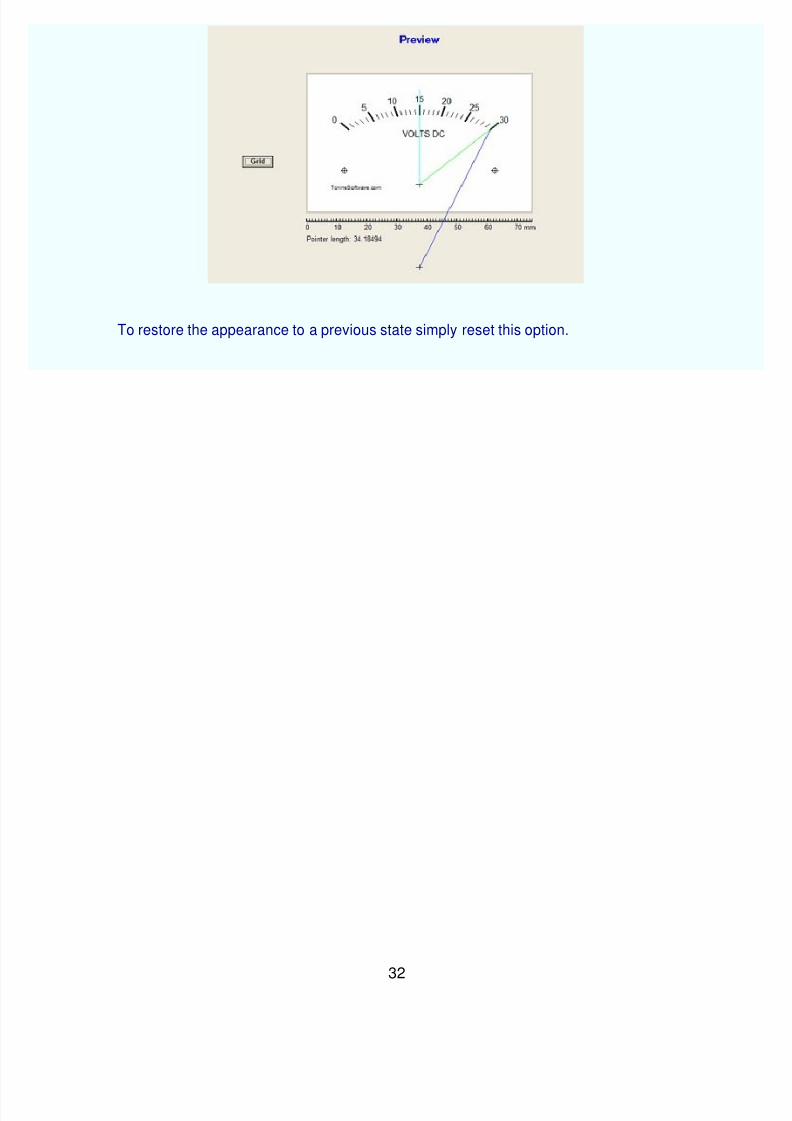
To restore the appearance to a previous state simply reset this option.
This on/off function is independent of the text items added using the Text Entry screen.To delete any of those items simply delete the text string in the appropriate textbox.
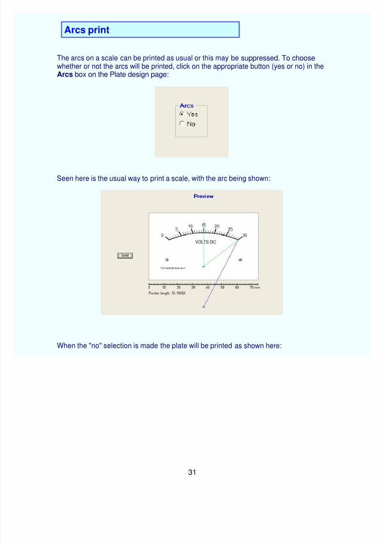
The arcs on a scale can be printed as usual or this may be suppressed. To choosewhether or not the arcs will be printed, click on the appropriate button (yes or no) in the Arcs box on the Plate design page:
Seen here is the usual way to print a scale, with the arc being shown:
When the "no" selection is made the plate will be printed as shown here:
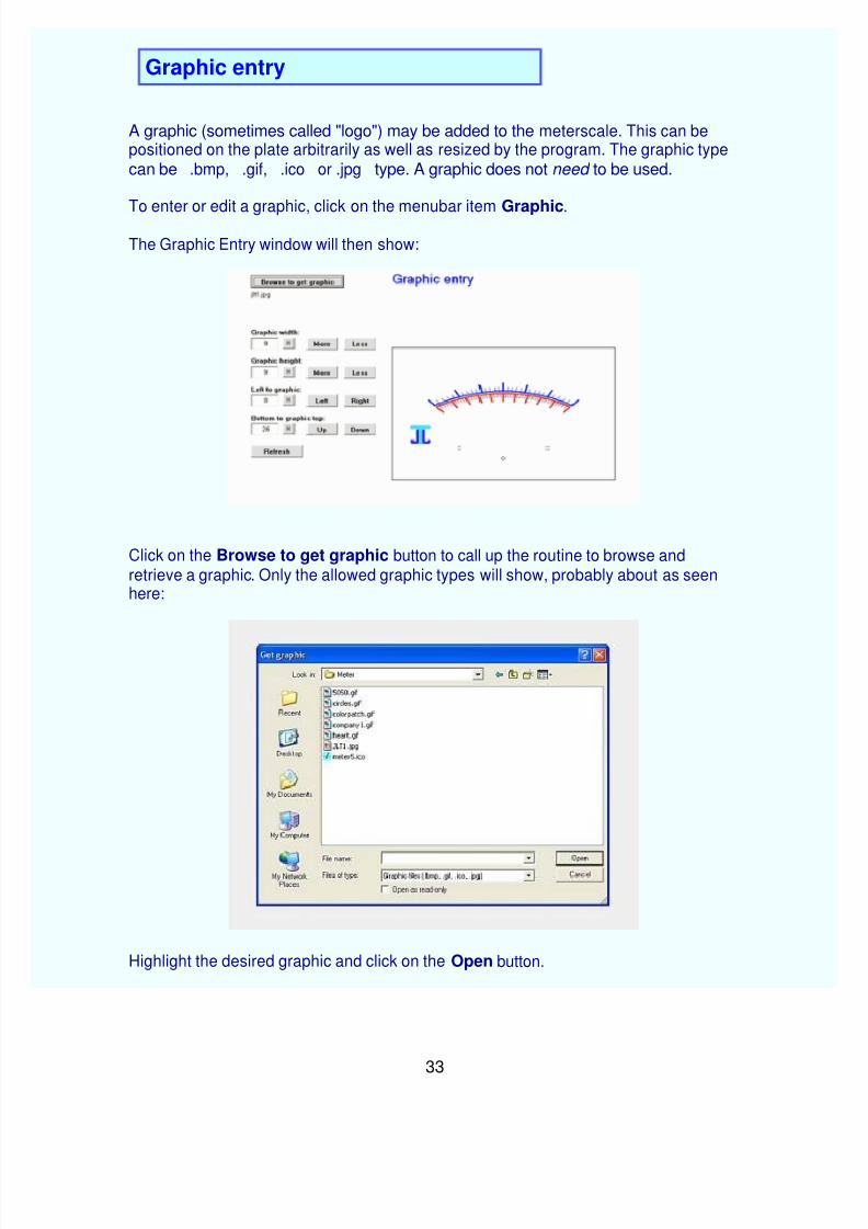
A graphic (sometimes called "logo") may be added to the meterscale. This can bepositioned on the plate arbitrarily as well as resized by the program. The graphic typecan be .bmp, .gif, .ico or .jpg type. A graphic does not need to be used.
To enter or edit a graphic, click on the menubar item Graphic.
The Graphic Entry window will then show:
Click on the Browse to get graphic button to call up the routine to browse andretrieve a graphic. Only the allowed graphic types will show, probably about as seen here:
Highlight the desired graphic and click on the Open button.
We are now back at the Graphic Entry screen and the chosen graphic is shown in asummary of the plate so that the graphic can be seen in context with the scale.
You may position and resize the graphic using the set of buttons. You may also enterthe new number(s) into the textboxes. If that is done use the Refresh button to enter
those numbers into the system.
The graphic can be turned on or off by using the Yes/No entry on the Plate designpage.
Significant resizing of a graphic, either making it wider or narrower, or taller or shorter,may result in a distorted reproduction. It is best to use an external graphics program tosignificantly resize a graphic.
Meter has the capability to compensate for meter movement nonlinearity. Thisprocedure allows correction of the nonlinearity frequently found in less-expensivemeters. This routine can also be used to advantage in creating special scales, butbear in mind that all scales on the plate will have the same degree of correction. If the plate has but a single scale this is of no concern.
To use the Linearity procedure, go to the Plate Design page and click on the Linearity
button. This takes us to the Linearity routine.
A set of textboxes where currents ("x-axis") and their resulting deflections ("y-axis") can
be entered is at the left side of the page. After any such entries are made press theAccept these entries button.
The entries can also be made by using the mouse to "drag and drop" the segment junctions in the plot. Six such segments are available to produce the correction.
The end points (at zero current and at fullscale current) cannot be changed. Entries arealways checked to confirm that they are legitimate, resulting in a realizable function.The process is blocked until the last-entered point is corrected.
The resultng transfer is then shown as a graph on the right side of the page. Beneath
that graph is a ruler-like presentation of the meter deflection.
Clicking on the Save this curve button saves the transfer data to the hard drive usinga user-specified location and name.
Clicking on the Get old curve button retrieves one of these earlier-saved curves.
At any time the curve can be restored to a linear function by clicking on the Restore tolinear button.
Clicking on the Show table button shows the slopes of each of the six segments alongwith a 50-point table of X and Y values.
Clicking on the Return to Plate design button exits from this process and takes thedesigner to the Plate Design page. At this point the most likely thing to be done is toclick on the Preview button to see how the linearity correction looks.
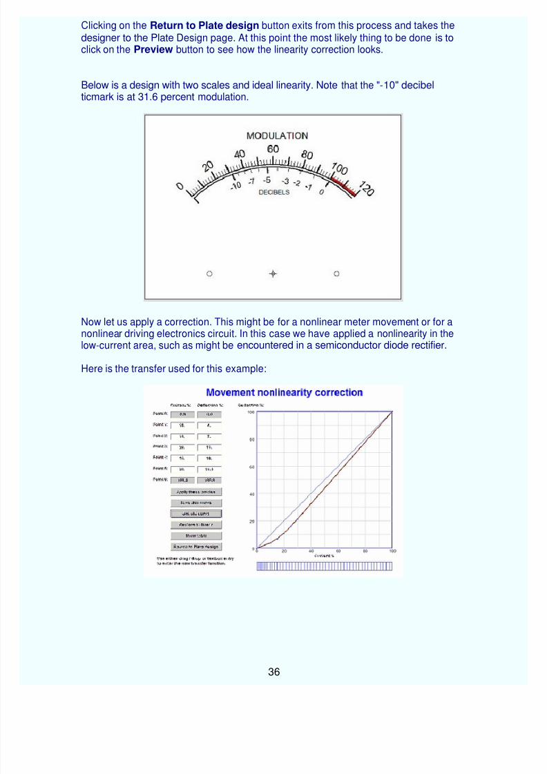
Below is a design with two scales and ideal linearity. Note that the "-10" decibelticmark is at 31.6 percent modulation.
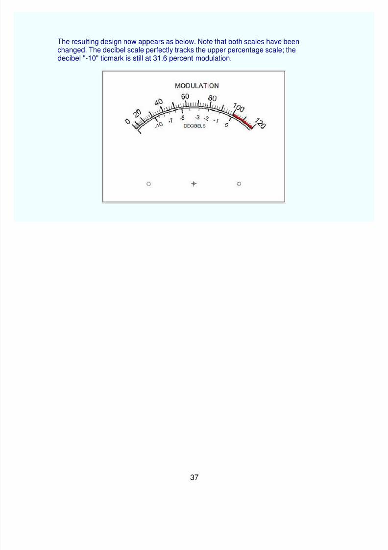
Now let us apply a correction. This might be for a nonlinear meter movement or for anonlinear driving electronics circuit. In this case we have applied a nonlinearity in thelow-current area, such as might be encountered in a semiconductor diode rectifier.
The resulting design now appears as below. Note that both scales have beenchanged. The decibel scale perfectly tracks the upper percentage scale; the decibel "-10" ticmark is still at 31.6 percent modulation.
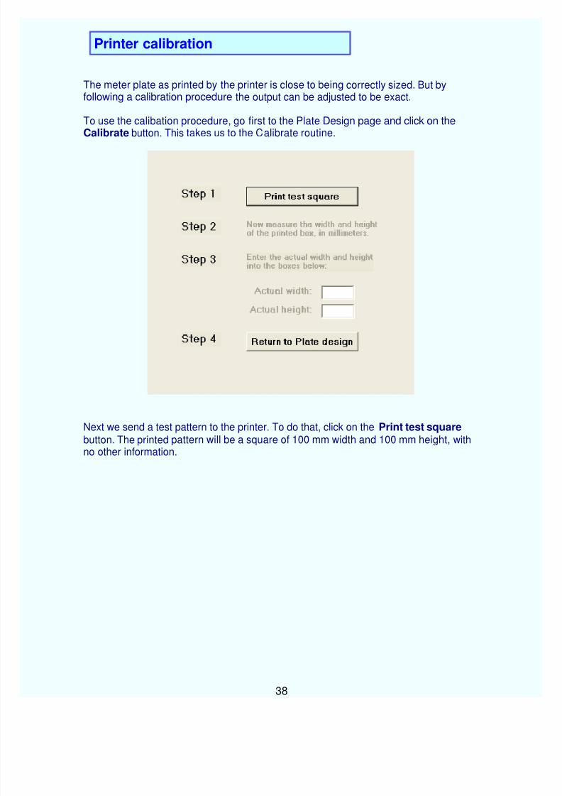
The meter plate as printed by the printer is close to being correctly sized. But byfollowing a calibration procedure the output can be adjusted to be exact.
To use the calibation procedure, go first to the Plate Design page and click on theCalibrate button. This takes us to the Calibrate routine.
Next we send a test pattern to the printer. To do that, click on the Print test square button. The printed pattern will be a square of 100 mm width and 100 mm height, withno other information.
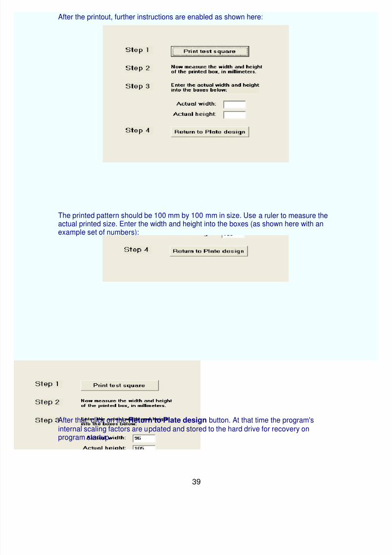
After the printout, further instructions are enabled as shown here:
The printed pattern should be 100 mm by 100 mm in size. Use a ruler to measure theactual printed size. Enter the width and height into the boxes (as shown here with anexample set of numbers):
After that, click on the Return to Plate design button. At that time the program's internal scaling factors are updated and stored to the hard drive for recovery onprogram startup.
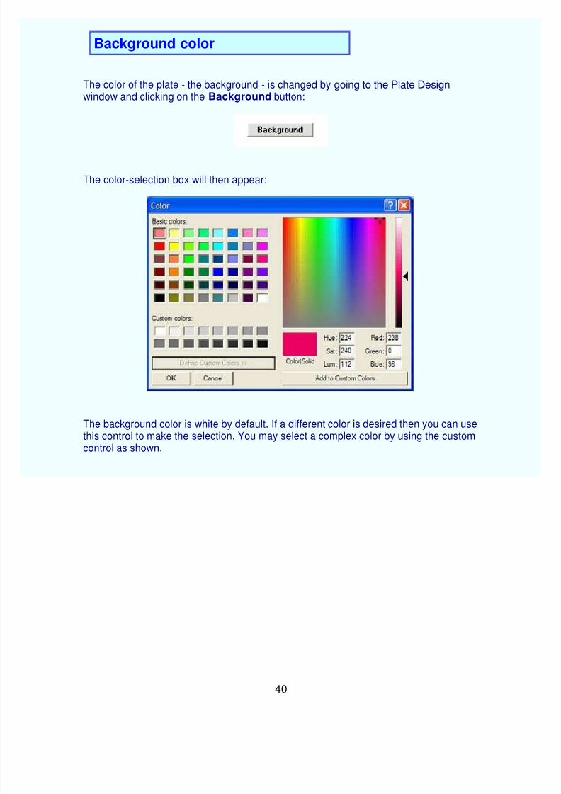
The color of the plate - the background - is changed by going to the Plate Designwindow and clicking on the Background button:
The color-selection box will then appear:
The background color is white by default. If a different color is desired then you can usethis control to make the selection. You may select a complex color by using the customcontrol as shown.
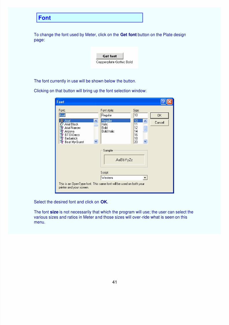
To change the font used by Meter, click on the Get font button on the Plate designpage:
The font currently in use will be shown below the button.
Clicking on that button will bring up the font selection window:
Select the desired font and click on OK.
The font size is not necessarily that which the program will use; the user can select thevarious sizes and ratios in Meter and those sizes will over-ride what is seen on thismenu.
On a global basis, the decimal delineator for value entry may be either "." or ","according to the computer's regional setting.
This program has been modified to use the regional setting for the decimal point.
Should you have a problem with the decimal, try using the "other" kind: if you normallyuse a period (".") try the comma (",") and also the other way around.
The scale uses only "." for printout to the plate.
Decimal point delineation is thought to be correct. If you are having a problem with thisplease send us an e-mail including your regional and keyboard settings.
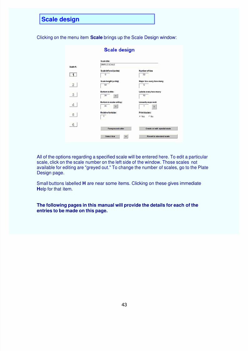
Clicking on the menu item Scale brings up the Scale Design window:
All of the options regarding a specified scale will be entered here. To edit a particularscale, click on the scale number on the left side of the window. Those scales notavailable for editing are "greyed out." To change the number of scales, go to the PlateDesign page.
Small buttons labelled H are near some items. Clicking on these gives immediateHelp for that item.
The following pages in this manual will provide the details for each of theentries to be made on this page.
On the Scale design page is the place where you select which scale to edit. The scaleto be edited is chosen by clicking on the appropriate scale number in the Edit scale # box:
That illustration shows that this plate has two scales and scale number two has beenselected for editing. Because there are only two scales, the remaining scales are not available for editing; this is shown by their being "greyed out."
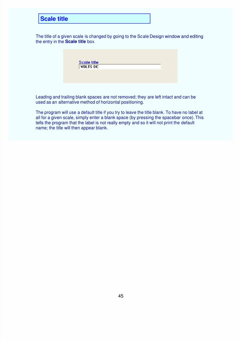
The title of a given scale is changed by going to the Scale Design window and editingthe entry in the Scale title box.
Leading and trailing blank spaces are not removed; they are left intact and can beused as an alternative method of horizontal positioning.
The program will use a default title if you try to leave the title blank. To have no label at
all for a given scale, simply enter a blank space (by pressing the spacebar once). Thistells the program that the label is not really empty and so it will not print the defaultname; the title will then appear blank.
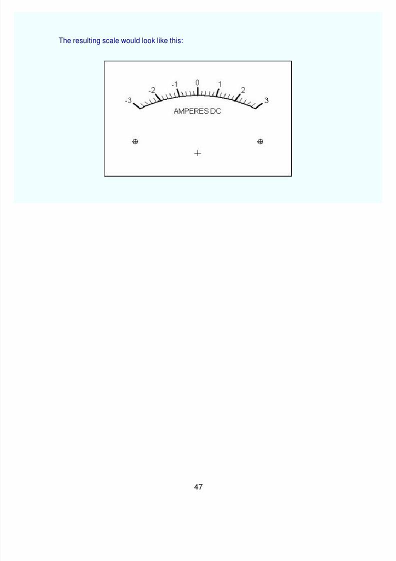
The values for a given scale (volts, amperes, etc.) are changed by going to the ScaleDesign window and editing the items in the Scale left end and Scale length boxes.
Such an entry pair will yield this scale:
This is the most common kind of scale in that the left-end value will be zero. Scaleswith left-end values other than zero are easily designed.
An example of this would be a "zero-center" meter. For example letus design a scalewith a left end reading of -3 and a right end reading of +3. For that design the scale leftend would be -3 and the scale length would be 6. The entries would then appear asshown here:
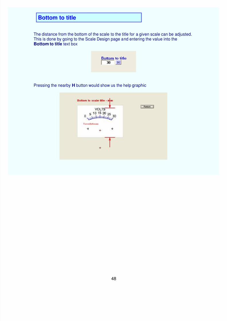
The distance from the bottom of the scale to the title for a given scale can be adjusted.This is done by going to the Scale Design page and entering the value into theBottom to title text box
Pressing the nearby H button would show us the help graphic
The distance from the bottom of the scale to the top of a scale arc - the ceiling - isadjusted by going to the Scale Design page and entering the value into the Bottom toscale ceiling text box
Pressing the nearby H button would show us the help graphic
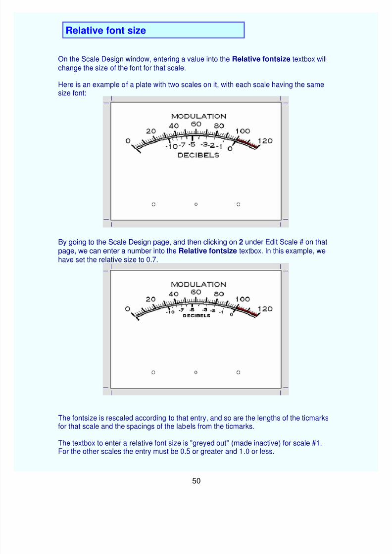
On the Scale Design window, entering a value into the Relative fontsize textbox will
change the size of the font for that scale.
Here is an example of a plate with two scales on it, with each scale having the same
size font:
By going to the Scale Design page, and then clicking on 2 under Edit Scale # on thatpage, we can enter a number into the Relative fontsize textbox. In this example, wehave set the relative size to 0.7.
The fontsize is rescaled according to that entry, and so are the lengths of the ticmarksfor that scale and the spacings of the labels from the ticmarks.
The textbox to enter a relative font size is "greyed out" (made inactive) for scale #1.For the other scales the entry must be 0.5 or greater and 1.0 or less.
The color of a given scale is changed by going to the Scale Design window andclicking on the Foreground color button:
The color-selection box will then appear:
Scale colors are black by default. If a color has been chosen it will be retained if youpress the Cancel button on this control. You may select a complex color by using thecustom control as shown.
The color chosen will apply to that scale and its associated text.
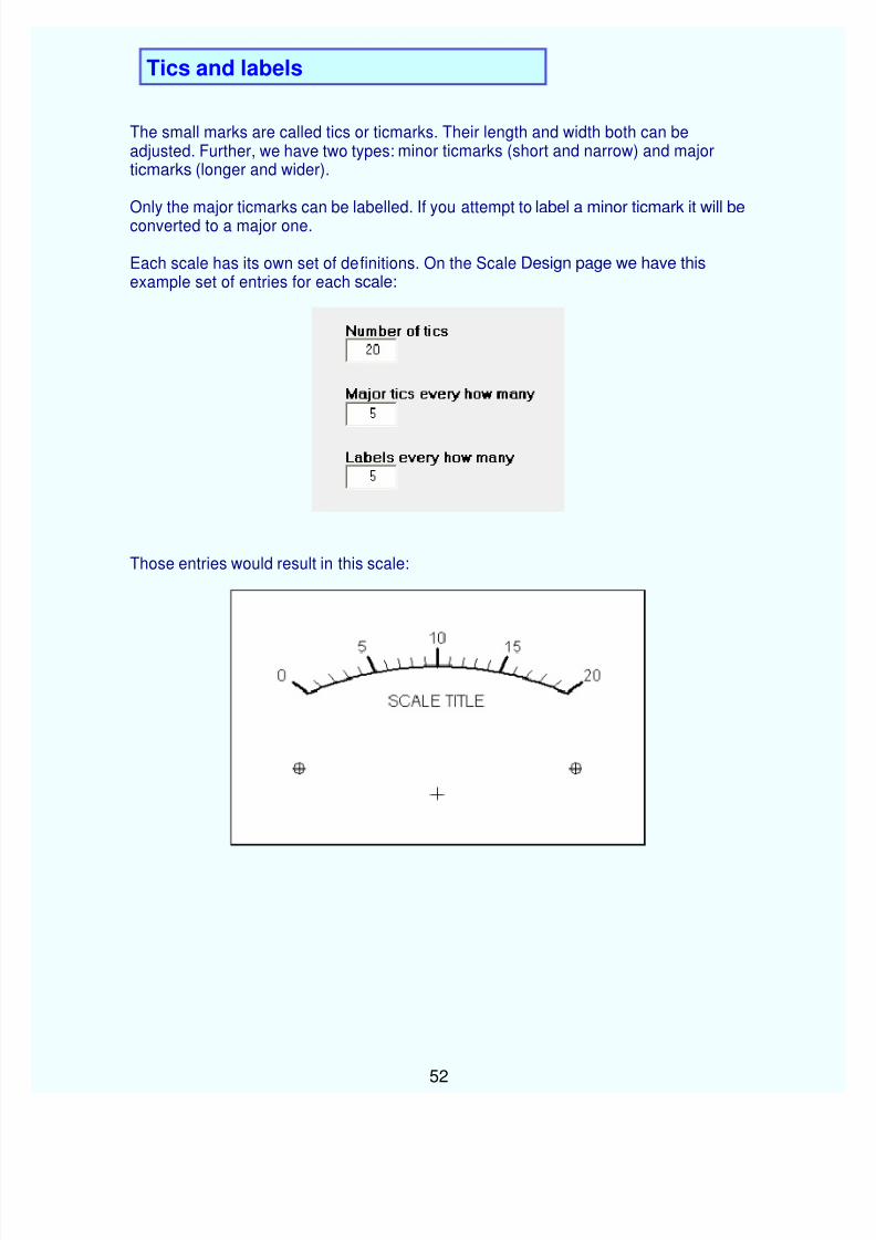
The small marks are called tics or ticmarks. Their length and width both can beadjusted. Further, we have two types: minor ticmarks (short and narrow) and majorticmarks (longer and wider).
Only the major ticmarks can be labelled. If you attempt to label a minor ticmark it will beconverted to a major one.
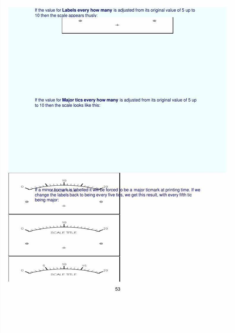
Each scale has its own set of definitions. On the Scale Design page we have thisexample set of entries for each scale:
If the value for Labels every how many is adjusted from its original value of 5 up to10 then the scale appears thusly:
If the value for Major tics every how many is adjusted from its original value of 5 upto 10 then the scale looks like this:
If a minor ticmark is labelled it will be forced to be a major ticmark at printing time. If wechange the labels back to being every five tics, we get this result, with every fifth ticbeing major:
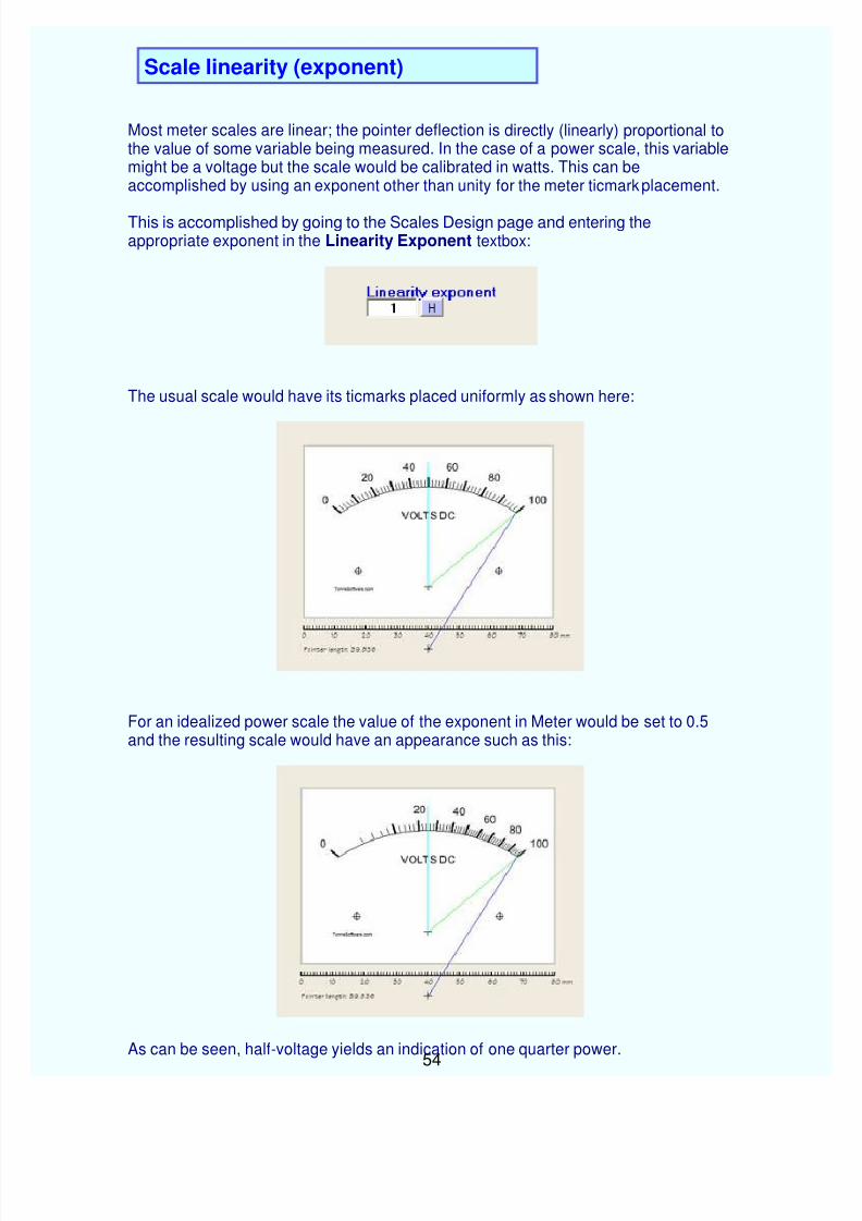
Most meter scales are linear; the pointer deflection is directly (linearly) proportional tothe value of some variable being measured. In the case of a power scale, this variablemight be a voltage but the scale would be calibrated in watts. This can beaccomplished by using an exponent other than unity for the meter ticmark placement.
This is accomplished by going to the Scales Design page and entering theappropriate exponent in the Linearity Exponent textbox:
The usual scale would have its ticmarks placed uniformly as shown here:
For an idealized power scale the value of the exponent in Meter would be set to 0.5and the resulting scale would have an appearance such as this:
As can be seen, half-voltage yields an indication of one quarter power.
Clicking on the menu item Scale brings up the Scale Design window. In the lower-righthand corner is the Generate special scale button.
Clicking on that button takes you to the special scale menu where you can choose fromany of the five available types. Examples of each are shown.
Each tic is normally printed but printing of each can be suppressed if desired. Andeach tic is normally made minor but can be changed to major if desired. And each ticcan be labelled or the labelling can be suppressed. This degree of control over thedesign allows a very large variety of designs.
Fontsize and background (plate) color are set in the Plate design page and theForeground color is set in the Scale design page, as usual. Further, the linearity of the
scale can be warped to some degree by using the Linearity entry box. This item isinitialized to unity.
The following pages illustrate the special scales that are available in Meter.
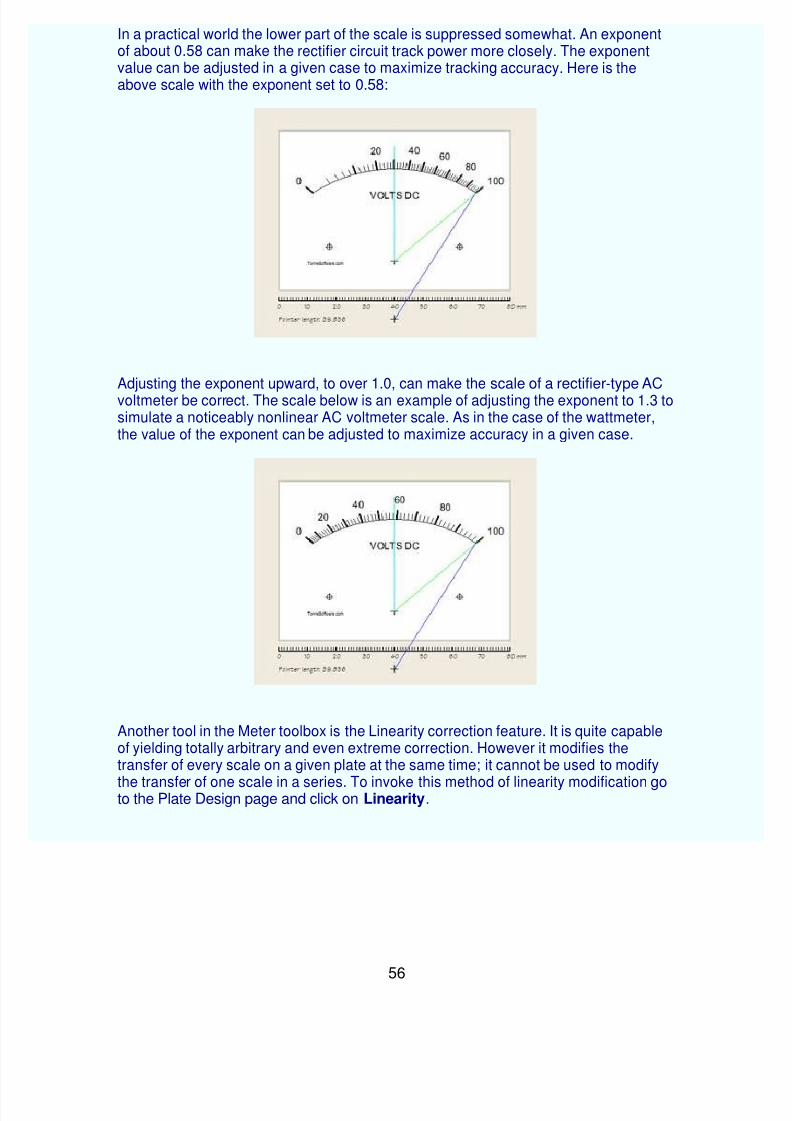
In a practical world the lower part of the scale is suppressed somewhat. An exponentof about 0.58 can make the rectifier circuit track power more closely. The exponent value can be adjusted in a given case to maximize tracking accuracy. Here is theabove scale with the exponent set to 0.58:
Adjusting the exponent upward, to over 1.0, can make the scale of a rectifier-type ACvoltmeter be correct. The scale below is an example of adjusting the exponent to 1.3 tosimulate a noticeably nonlinear AC voltmeter scale. As in the case of the wattmeter,the value of the exponent can be adjusted to maximize accuracy in a given case.
Another tool in the Meter toolbox is the Linearity correction feature. It is quite capableof yielding totally arbitrary and even extreme correction. However it modifies thetransfer of every scale on a given plate at the same time; it cannot be used to modify
the transfer of one scale in a series. To invoke this method of linearity modification goto the Plate Design page and click on Linearity.
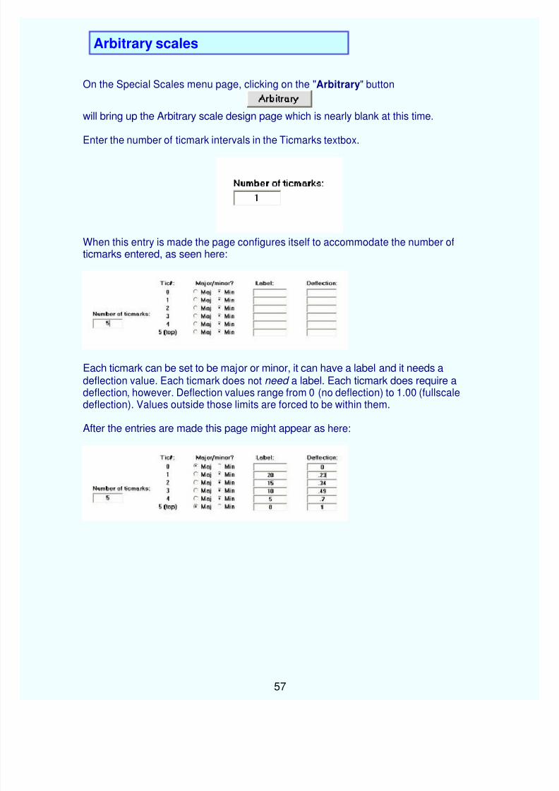
On the Special Scales menu page, clicking on the "Arbitrary" button
will bring up the Arbitrary scale design page which is nearly blank at this time.
Enter the number of ticmark intervals in the Ticmarks textbox.
When this entry is made the page configures itself to accommodate the number ofticmarks entered, as seen here:
Each ticmark can be set to be major or minor, it can have a label and it needs adeflection value. Each ticmark does not need a label. Each ticmark does require adeflection, however. Deflection values range from 0 (no deflection) to 1.00 (fullscaledeflection). Values outside those limits are forced to be within them.
After the entries are made this page might appear as here:
Clicking on the Preview button shows what the scale would look like:
If you want to abandon this entire process click on the Ignore button to go back to theScale design page.
If you are satisfied with the design, click on the Accept button:
The design will then be read into the system and you will be returned to the Scaledesign page.
The values for the previous design (prior to conversion to one of the special scales)are still in memory until the program is exited. If you have made an error and want to restore that earlier design, go to the Scale Design page and click on the Revert tostandard scale button.
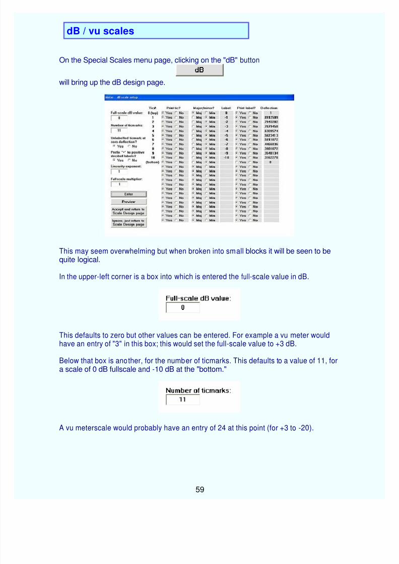
On the Special Scales menu page, clicking on the "dB" button
will bring up the dB design page.
This may seem overwhelming but when broken into small blocks it will be seen to bequite logical.
In the upper-left corner is a box into which is entered the full-scale value in dB.
This defaults to zero but other values can be entered. For example a vu meter wouldhave an entry of "3" in this box; this would set the full-scale value to +3 dB.
Below that box is another, for the number of ticmarks. This defaults to a value of 11, fora scale of 0 dB fullscale and -10 dB at the "bottom."
A vu meterscale would probably have an entry of 24 at this point (for +3 to -20).
The dB scales are designed by starting at full scale and working downward. It isapparent then that the design process never reaches down to the zero-deflection point. But it is customary to have a ticmark at zero deflection. Accordingly the program willask if you want such a mark.
This option defaults to "Yes" but can be changed by clicking on the "No" button.
It is customary to have the "+" symbol prefixed to positive decibel vallues. The programasks if this should be done.
This option defaults to "Yes" but can be changed by clicking on the "No" button.
As with standard scales, a nonlinearity (typically due to diode rectifier nonlinearity) canbe invoked.
This defaults to 1.0 but other values can be used.
By default the highest dB number is at fullscale. This can be adjusted over slight limitsby using the fullscale multiplier function:
This number defaults to unity (1.0). It can be adjusted over the range of 0.7 to 1.1 toallow the decibel scale to be in exact agreement with an associated percentmodulation scale or any other voltage scales.
After any items are changed on this page the Enter button must be pressed.
This updates the matrix of options which occupy most of the page. At that time it wouldbe best to immediately see what the design at that point looks like. To do that, click on the Preview button.
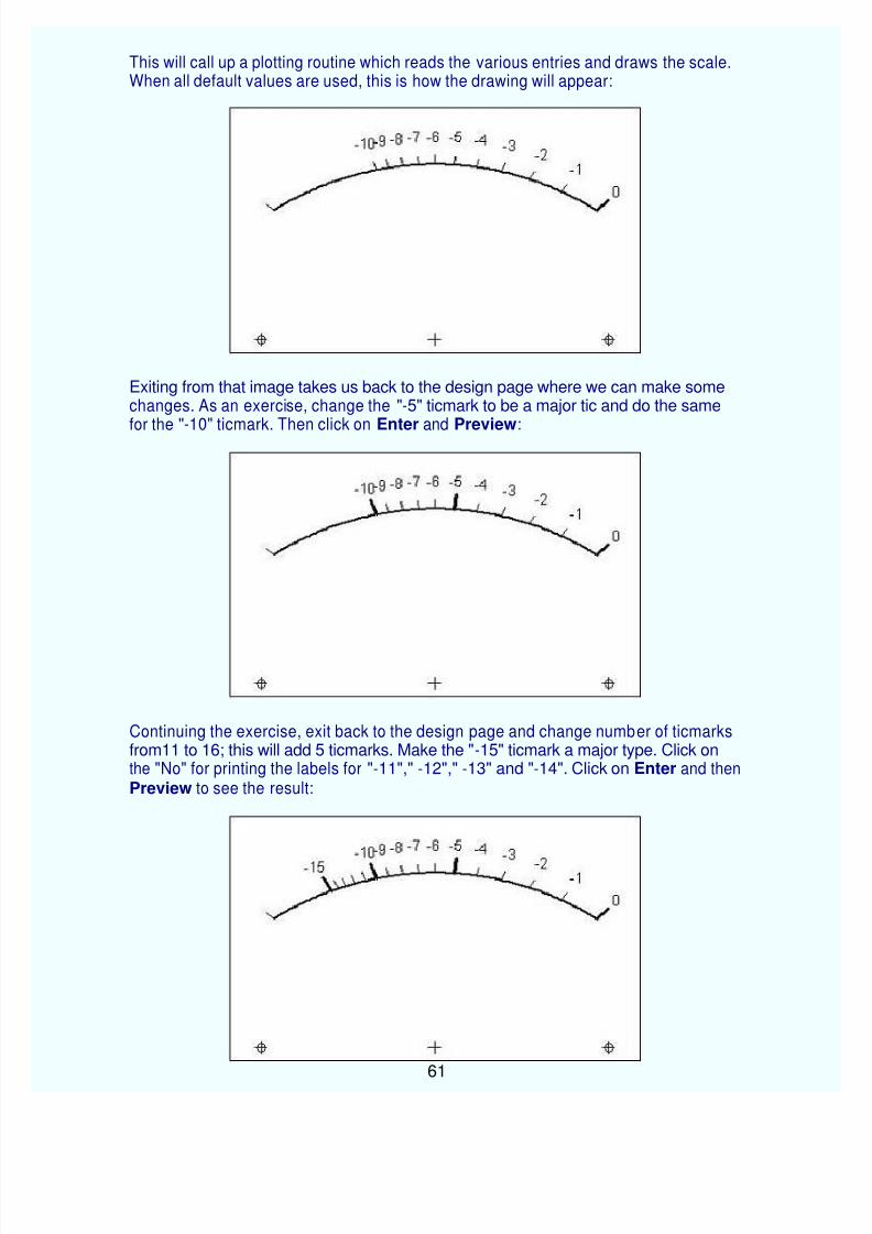
This will call up a plotting routine which reads the various entries and draws the scale.When all default values are used, this is how the drawing will appear:
Exiting from that image takes us back to the design page where we can make somechanges. As an exercise, change the "-5" ticmark to be a major tic and do the same
for the "-10" ticmark. Then click on Enter and Preview:
Continuing the exercise, exit back to the design page and change number of ticmarksfrom11 to 16; this will add 5 ticmarks. Make the "-15" ticmark a major type. Click onthe "No" for printing the labels for "-11"," -12"," -13" and "-14". Click on Enter and then Preview to see the result:
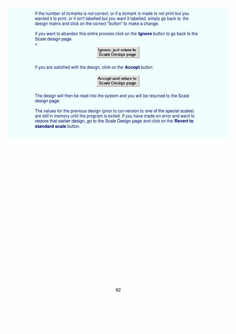
If the number of ticmarks is not correct, or if a ticmark is made to not print but youwanted it to print, or it isn't labelled but you want it labelled, simply go back to thedesign matrix and click on the correct "button" to make a change.
If you want to abandon this entire process click on the Ignore button to go back to theScale design page.<
If you are satisfied with the design, click on the Accept button:
The design will then be read into the system and you will be returned to the Scaledesign page.
The values for the previous design (prior to conversion to one of the special scales)
are still in memory until the program is exited. If you have made an error and want to restore that earlier design, go to the Scale Design page and click on the Revert to
On the Special Scales menu page, clicking on the "VSWR" button
will bring up the VSWR design page which is nearly blank at this time.
For this run-through, click on the 1.0 button. That design will be shown.
You may also click on the other designs. They differ only in the resolution of theticmarks.
Modest system nonlinearities can be accommodated by adjusting the value entered inthe Linearity box. The value of this variable defaults to unity (1.0) but can be adjusted toaccount for (as an example) diode nonlinearity.
If you want to abandon this entire process click on the Ignore button to go back to the
Scale design page.
If you are satisfied with the design, click on the Accept button:
The design will then be read into the system and you will be returned to the Scaledesign page.
The values for the previous design (prior to conversion to one of the special scales)are still in memory until the program is exited. If you have made an error and want to restore that earlier design, go to the Scale Design page and click on the Revert tostandard scale button.
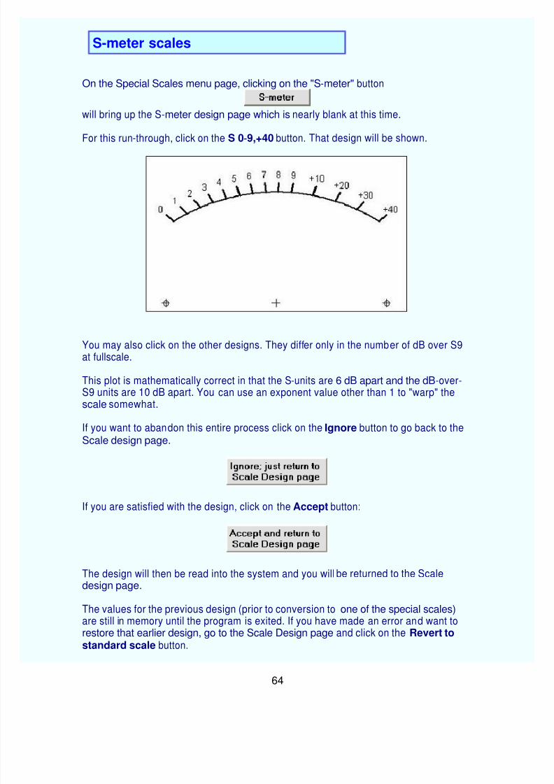
On the Special Scales menu page, clicking on the "S-meter" button
will bring up the S-meter design page which is nearly blank at this time.
For this run-through, click on the S 0-9,+40 button. That design will be shown.
You may also click on the other designs. They differ only in the number of dB over S9at fullscale.
This plot is mathematically correct in that the S-units are 6 dB apart and the dB-over-S9 units are 10 dB apart. You can use an exponent value other than 1 to "warp" thescale somewhat.
If you want to abandon this entire process click on the Ignore button to go back to theScale design page.
If you are satisfied with the design, click on the Accept button:
The design will then be read into the system and you will be returned to the Scaledesign page.
The values for the previous design (prior to conversion to one of the special scales)are still in memory until the program is exited. If you have made an error and want to restore that earlier design, go to the Scale Design page and click on the Revert tostandard scale button.
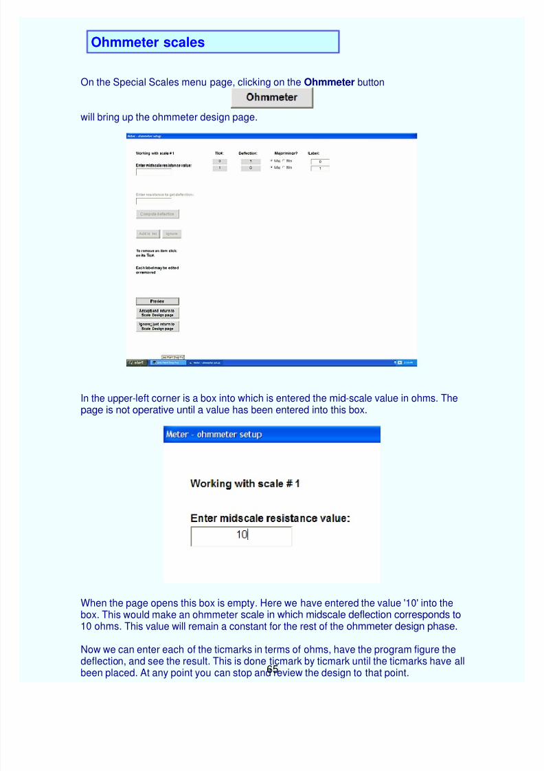
On the Special Scales menu page, clicking on the Ohmmeter button
will bring up the ohmmeter design page.
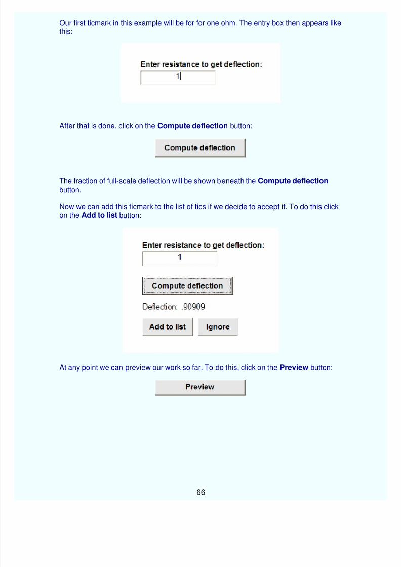
In the upper-left corner is a box into which is entered the mid-scale value in ohms. Thepage is not operative until a value has been entered into this box.
When the page opens this box is empty. Here we have entered the value '10' into thebox. This would make an ohmmeter scale in which midscale deflection corresponds to10 ohms. This value will remain a constant for the rest of the ohmmeter design phase.
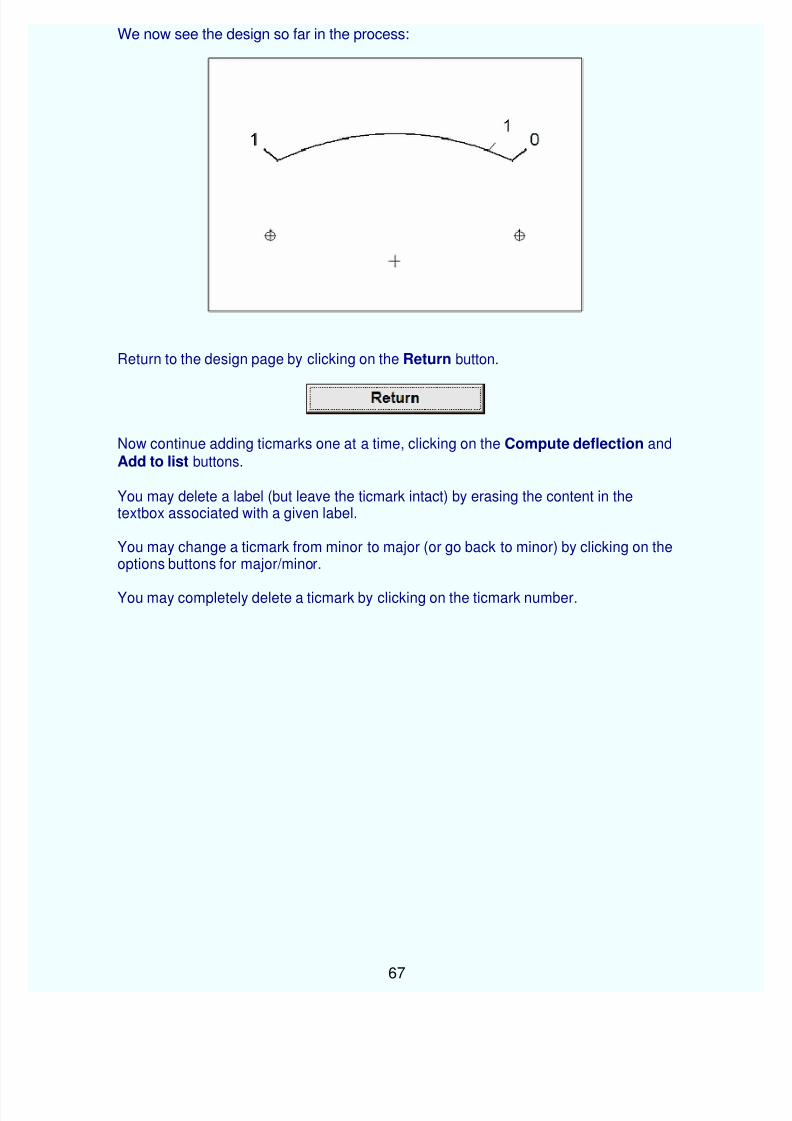
Now we can enter each of the ticmarks in terms of ohms, have the program figure thedeflection, and see the result. This is done ticmark by ticmark until the ticmarks have all
been placed. At any point you can stop and review the design to that point.
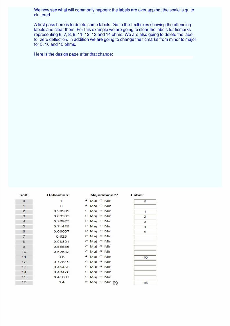
We now see what will commonly happen: the labels are overlapping; the scale is quitecluttered.
A first pass here is to delete some labels. Go to the textboxes showing the offendinglabels and clear them. For this example we are going to clear the labels for ticmarks representing 6, 7, 8, 9, 11, 12, 13 and 14 ohms. We are also going to delete the labelfor zero deflection. In addition we are going to change the ticmarks from minor to majorfor 5, 10 and 15 ohms.
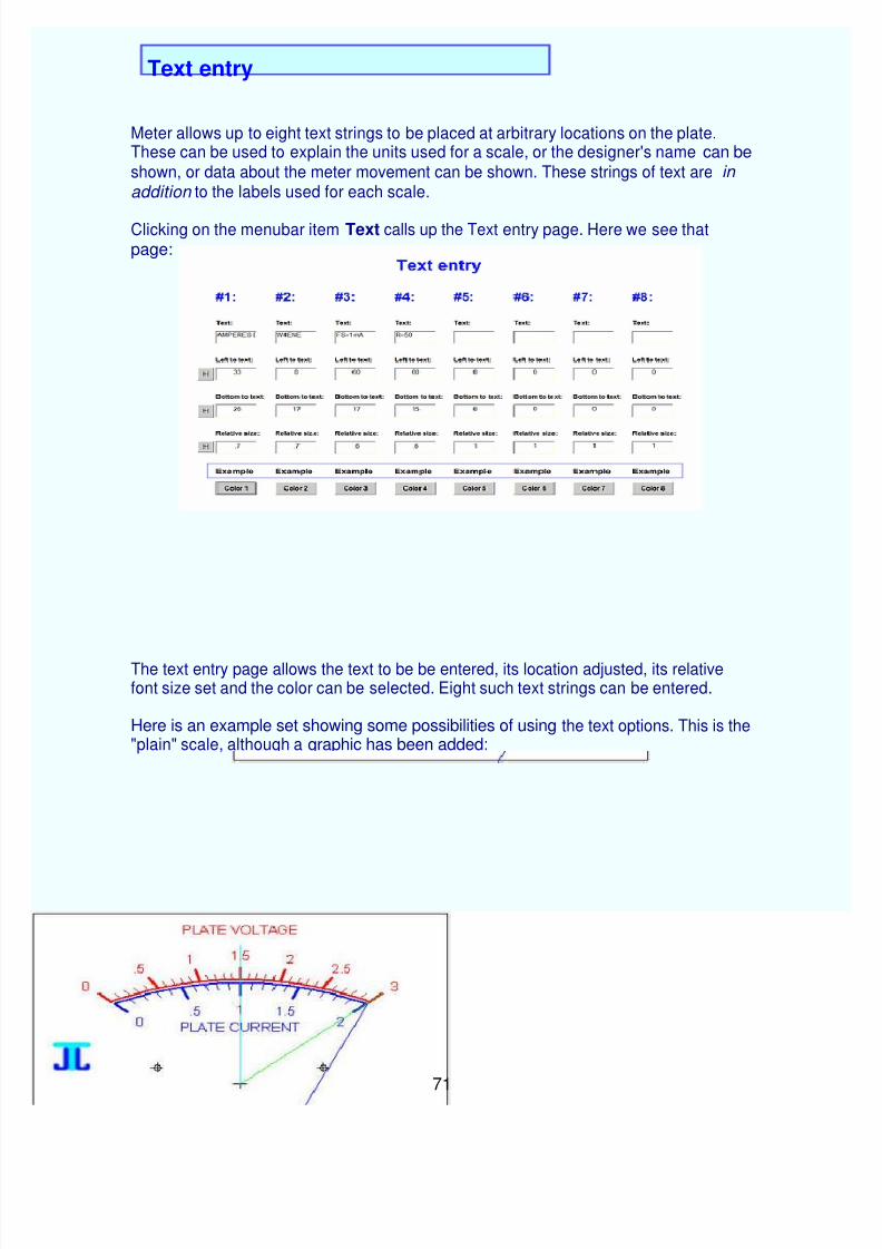
Meter allows up to eight text strings to be placed at arbitrary locations on the plate.These can be used to explain the units used for a scale, or the designer's name can be
Text entry
shown, or data about the meter movement can be shown. These strings of text are in
addition to the labels used for each scale.
Clicking on the menubar item Text calls up the Text entry page. Here we see thatpage:
The text entry page allows the text to be be entered, its location adjusted, its relativefont size set and the color can be selected. Eight such text strings can be entered.
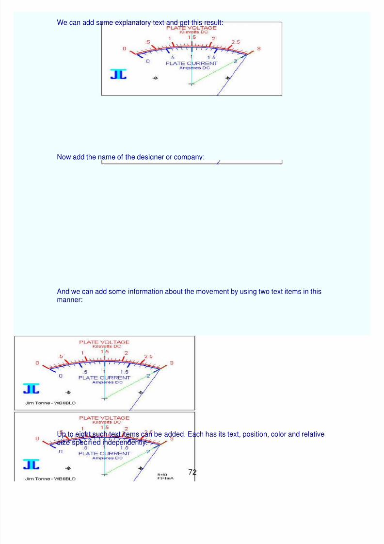
Here is an example set showing some possibilities of using the text options. This is the"plain" scale, although a graphic has been added:
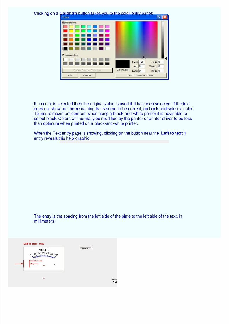
Clicking on a Color #n button takes you to the color entry panel:
If no color is selected then the original value is used if it has been selected. If the textdoes not show but the remaining traits seem to be correct, go back and select a color.
To insure maximum contrast when using a black-and-white printer it is advisable toselect black. Colors will normally be modified by the printer or printer driver to be lessthan optimum when printed on a black-and-white printer.
When the Text entry page is showing, clicking on the button near the Left to text 1 entry reveals this help graphic:
The entry is the spacing from the left side of the plate to the left side of the text, inmillimeters.
A graphic (sometimes called "logo") may be added to the meterscale. This can bepositioned on the plate arbitrarily as well as resized by the program. The graphic typecan be .bmp, .gif, .ico or .jpg type. A graphic does not need to be used.
To enter or edit a graphic, click on the menubar item Graphic.
The Graphic Entry window will then show:
Click on the Browse to get graphic button to call up the routine to browse andretrieve a graphic. Only the allowed graphic types will show, probably about as seen here:
Highlight the desired graphic and click on the Open button.
We are now back at the Graphic Entry screen and the chosen graphic is shown in asummary of the plate so that the graphic can be seen in context with the scale.
You may position and resize the graphic using the set of buttons. You may also enterthe new number(s) into the textboxes. If that is done use the Refresh button to enter
those numbers into the system.
The graphic can be turned on or off by using the Yes/No entry on the Plate designpage.
Significant resizing of a graphic, either making it wider or narrower, or taller or shorter,may result in a distorted reproduction. It is best to use an external graphics program tosignificantly resize a graphic.
Meter allows up to eight "highlights" to be used on each scale. These are commonlyused to indicate "off limits" or "overload" areas on a given scale. To add one or morehighlights, click on the menubar item Highlights and see the Highlight Entry screen:
Let us examine one of the entry blocks, in this case the first one on the far left.
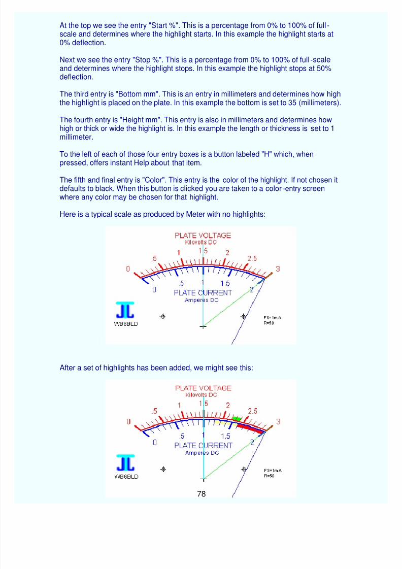
At the top we see the entry "Start %". This is a percentage from 0% to 100% of full-scale and determines where the highlight starts. In this example the highlight starts at 0% deflection.
Next we see the entry "Stop %". This is a percentage from 0% to 100% of full-scaleand determines where the highlight stops. In this example the highlight stops at 50% deflection.
The third entry is "Bottom mm". This is an entry in millimeters and determines how highthe highlight is placed on the plate. In this example the bottom is set to 35 (millimeters).
The fourth entry is "Height mm". This entry is also in millimeters and determines howhigh or thick or wide the highlight is. In this example the length or thickness is set to 1millimeter.
To the left of each of those four entry boxes is a button labeled "H" which, whenpressed, offers instant Help about that item.
The fifth and final entry is "Color". This entry is the color of the highlight. If not chosen itdefaults to black. When this button is clicked you are taken to a color-entry screen
where any color may be chosen for that highlight.
Here is a typical scale as produced by Meter with no highlights:
After a set of highlights has been added, we might see this:
Up to eight such highlights may be added to a plate. This plate illustrates the use ofthree.
The highlights are printed first on the plate and then the other items are printed on topof them. In this manner the highlights are in the "background" so the other items are notcovered or concealed.
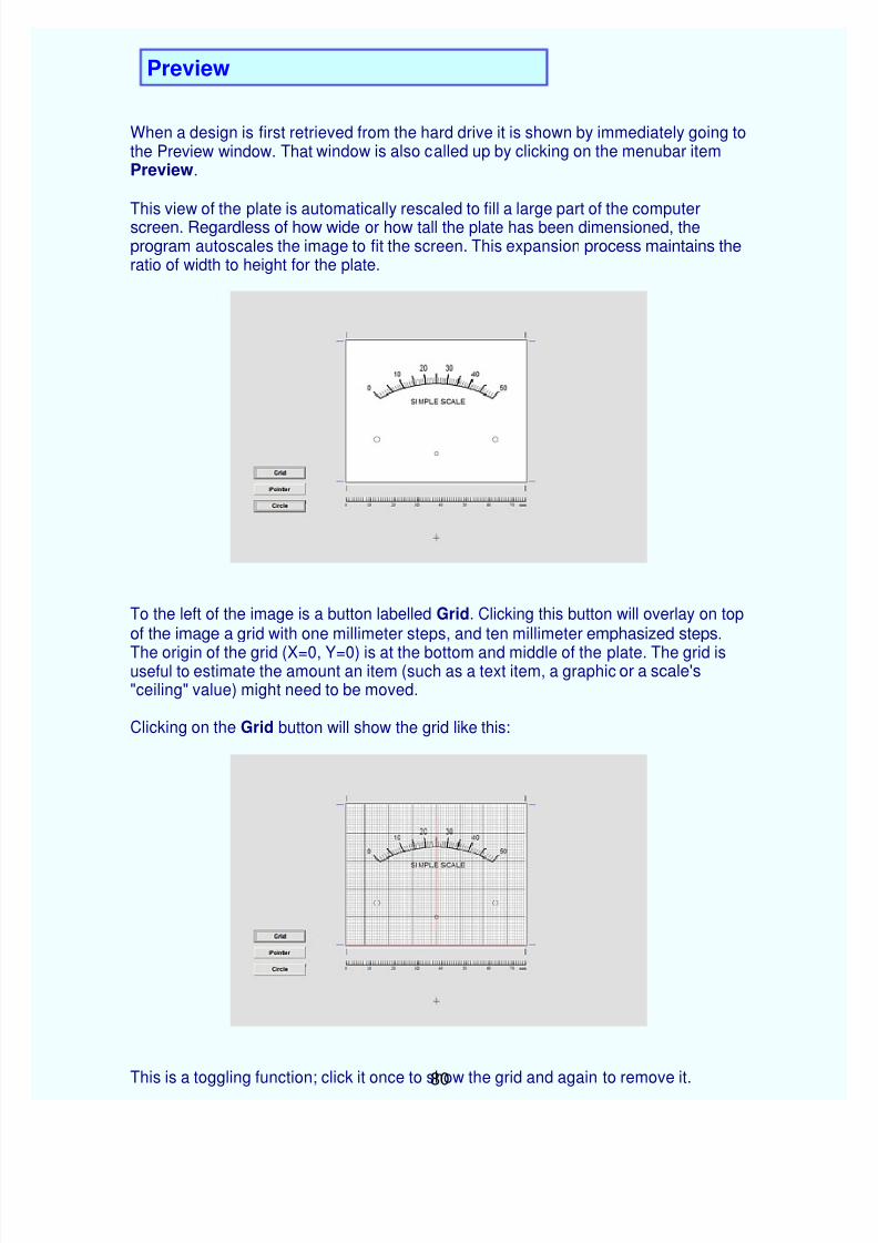
When a design is first retrieved from the hard drive it is shown by immediately going tothe Preview window. That window is also called up by clicking on the menubar item Preview.
This view of the plate is automatically rescaled to fill a large part of the computerscreen. Regardless of how wide or how tall the plate has been dimensioned, theprogram autoscales the image to fit the screen. This expansion process maintains theratio of width to height for the plate.
To the left of the image is a button labelled Grid. Clicking this button will overlay on topof the image a grid with one millimeter steps, and ten millimeter emphasized steps.
The origin of the grid (X=0, Y=0) is at the bottom and middle of the plate. The grid isuseful to estimate the amount an item (such as a text item, a graphic or a scale's"ceiling" value) might need to be moved.
Clicking on the Grid button will show the grid like this:
This is a toggling function; click it once to show the grid and again to remove it.
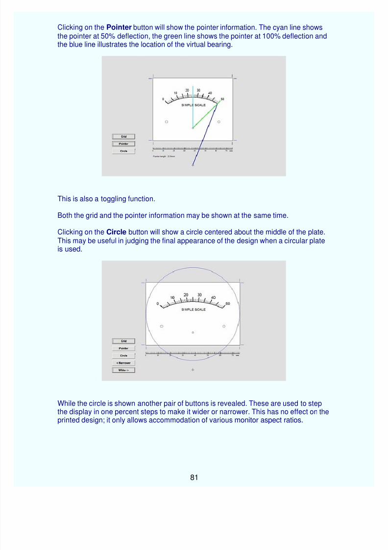
Clicking on the Pointer button will show the pointer information. The cyan line showsthe pointer at 50% deflection, the green line shows the pointer at 100% deflection andthe blue line illustrates the location of the virtual bearing.
This is also a toggling function.
Both the grid and the pointer information may be shown at the same time.
Clicking on the Circle button will show a circle centered about the middle of the plate.This may be useful in judging the final appearance of the design when a circular plateis used.
While the circle is shown another pair of buttons is revealed. These are used to stepthe display in one percent steps to make it wider or narrower. This has no effect on theprinted design; it only allows accommodation of various monitor aspect ratios.
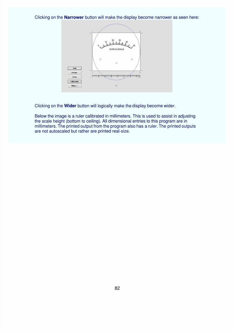
Clicking on the Narrower button will make the display become narrower as seen here:
Clicking on the Wider button will logically make the display become wider.
Below the image is a ruler calibrated in millimeters. This is used to assist in adjustingthe scale height (bottom to ceiling). All dimensional entries to this program are inmillimeters. The printed output from the program also has a ruler. The printed outputsare not autoscaled but rather are printed real-size.
This page was written to illustrate the mechanics of changing a meterscale using, ofcourse, Meter as the scale design aid. It does not cover the design of a particularscale but rather covers "how to do it" in some practical detail.
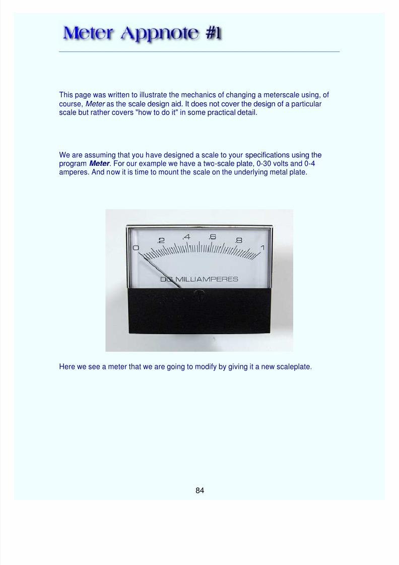
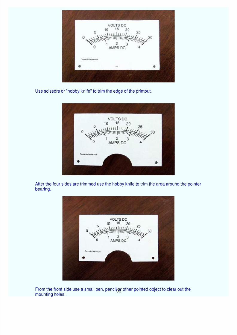
We are assuming that you have designed a scale to your specifications using theprogram Meter . For our example we have a two-scale plate, 0-30 volts and 0-4amperes. And now it is time to mount the scale on the underlying metal plate.
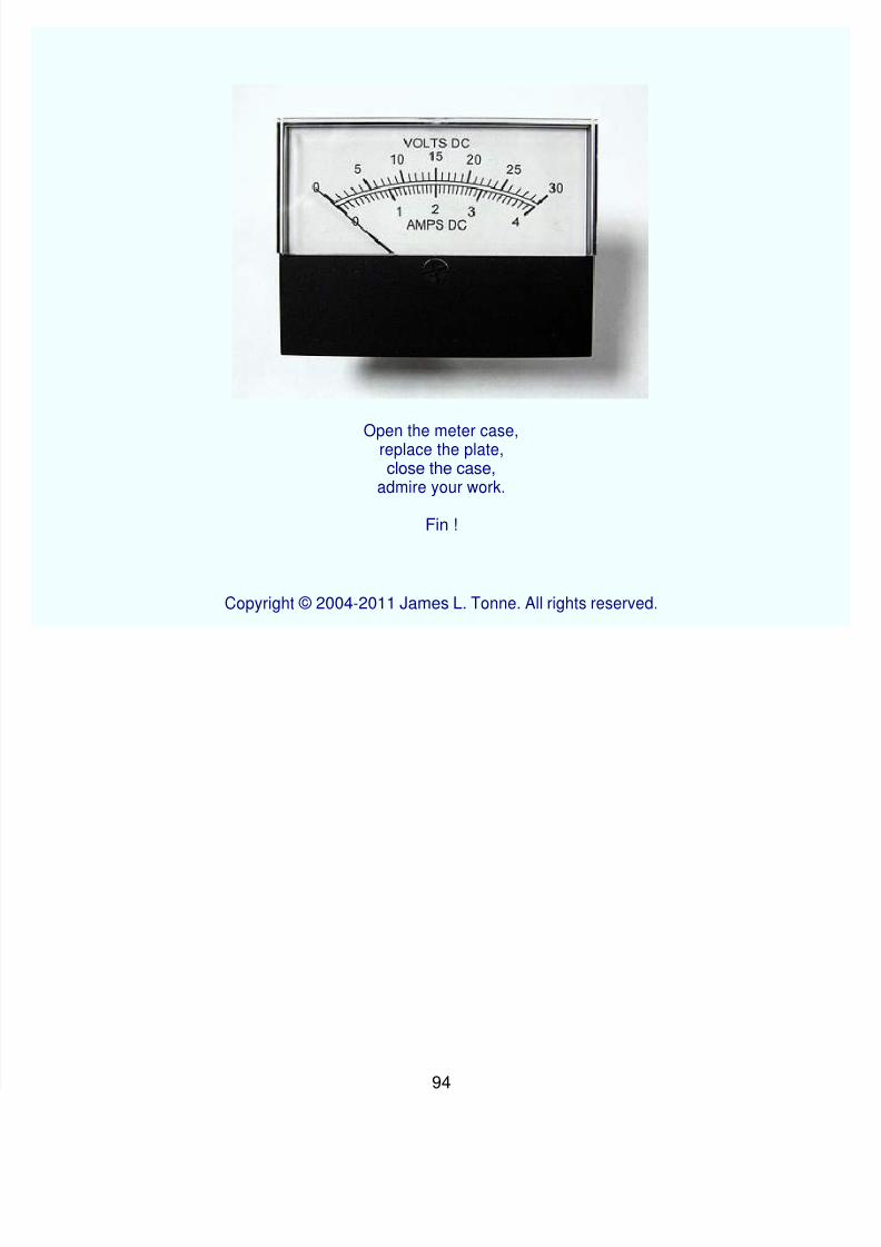
Here we see a meter that we are going to modify by giving it a new scaleplate.
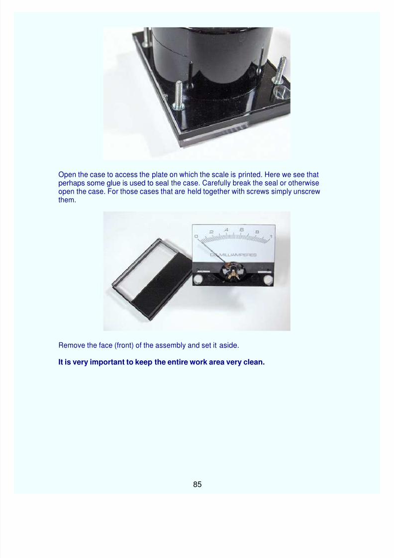
Open the case to access the plate on which the scale is printed. Here we see thatperhaps some glue is used to seal the case. Carefully break the seal or otherwiseopen the case. For those cases that are held together with screws simply unscrewthem.
Remove the face (front) of the assembly and set it aside.
It is very important to keep the entire work area very clean.
An obstacle that might be encountered is a plate with a "mirror" on it. This can showthrough most papers on which a scale would be printed. The mirror might very well bea thin sheet of plastic film which has been metalized. The best way to minimize thepossibility of the mirror showing through the printed paper is to use a paper which has sufficient thickness. Alternatively you could add another layer of paper between theplate and the printout.
The paper should be bright white and smooth. It does not need to be thick. Ye scribe
has used old photographs on which to print.
Now we can make various measurements and put them into the program Meter.
Measure the plate width (76 mm here).
Measure the plate height (45 mm here).
The measurement of width and height are not critical. If you wish, round them up to thenext higher millimeter or more.
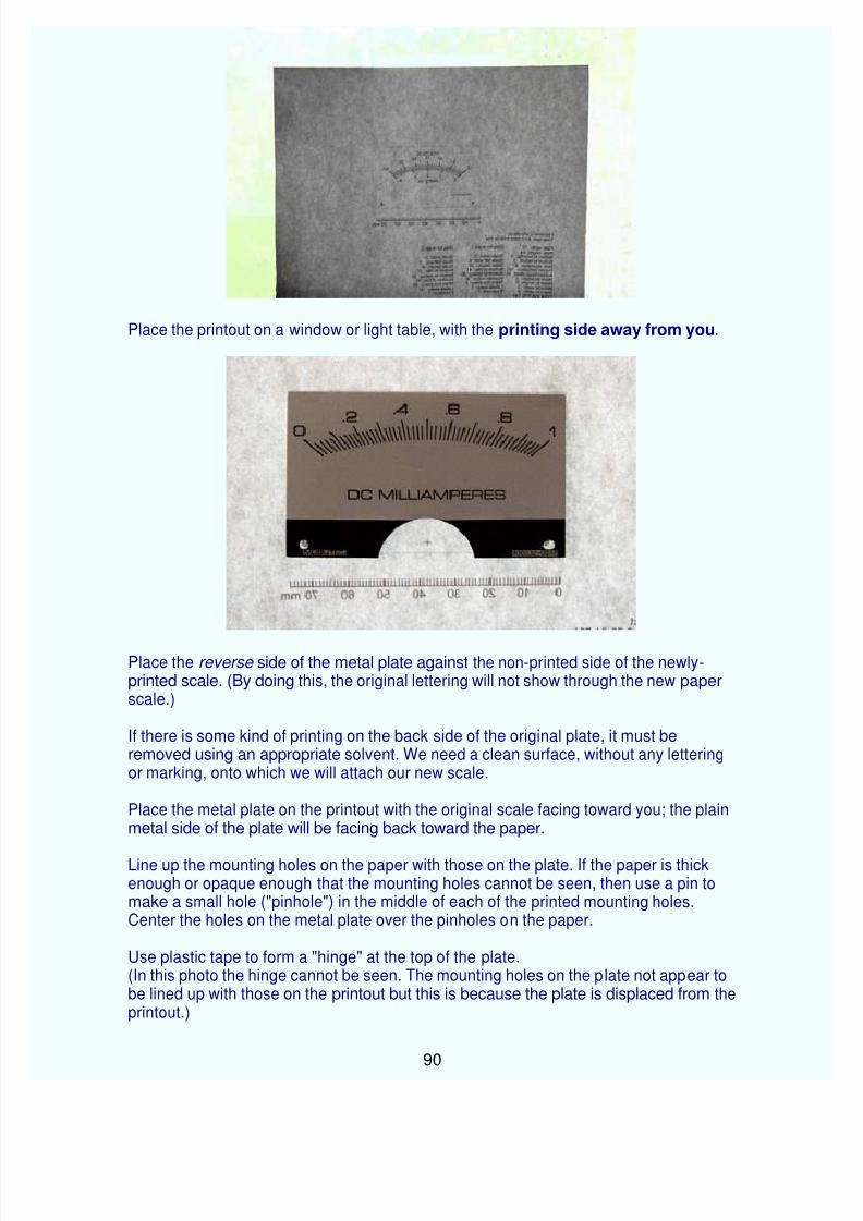
Place the printout on a window or light table, with the printing side away from you.
Place the reverse side of the metal plate against the non-printed side of the newly-printed scale. (By doing this, the original lettering will not show through the new paperscale.)
If there is some kind of printing on the back side of the original plate, it must beremoved using an appropriate solvent. We need a clean surface, without any letteringor marking, onto which we will attach our new scale.
Place the metal plate on the printout with the original scale facing toward you; the plainmetal side of the plate will be facing back toward the paper.
Line up the mounting holes on the paper with those on the plate. If the paper is thickenough or opaque enough that the mounting holes cannot be seen, then use a pin tomake a small hole ("pinhole") in the middle of each of the printed mounting holes.Center the holes on the metal plate over the pinholes on the paper.
Use plastic tape to form a "hinge" at the top of the plate. (In this photo the hinge cannot be seen. The mounting holes on the plate not appear tobe lined up with those on the printout but this is because the plate is displaced from theprintout.)


![User Manual Three Phase Energy Meter - INOGATE Manual Three Phase Energy Meter HXE310 CT & CTPT Meter Hexing Electrical Co., Ltd. [2013.3] Meter User Manual-HXE310 2 / 76 Introduction](https://static.documents.pub/doc/80x56/5aa750e17f8b9a50528c3353/user-manual-three-phase-energy-meter-manual-three-phase-energy-meter-hxe310-ct.jpg)


