Methanol is a clear liquid usually made from natural gas. It is a clean burning fuel, containing almost no sulphur or nitrogenous materials. It is a petrochemical that is used to make countless industrial and consumer products. In the future, methanol could be used as a source of hydrogen for fuel cells. Different concepts are in use to produce methanol looking always for higher plant efficiency and product quality.
All processes require the use of ex-tensive process analyzer systems to monitor both process chain and product quality. Siemens, a leader in process analytics, has proven over decades its capability to plan, engi-neer, manufacture, implement and service such analyzer systems.
This Case Study provides details about the Methanol process and related ana-lyzer tasks.
MethanolMethanol (CH3OH) is an important multipurpose base chemical, a sim-ple molecule which can be recov-ered from many resources, predom-inantly natural gas. By tradition, methanol is principally used to pro-duce formaldehyde, methyl tertiary butyl ether (MTBE) and acetic acid. To a lesser extend, methanol is used as a general solvent. Today, Metha-nol is projected to be increasingly used as a fuel, so a comparison to LNG could be made. Like LNG, meth-anol is manufactured from natural gas, but with higher capital costs per unit of energy. But it is easier and cheaper to transport.
Natural Gas (NG) is one of the cleanest, safest, and most useful of all energy sources. NG is colorless, shapeless, and odorless in its pure form. It is combustible, and when burned it emits lower levels of potentially harmful by-products into the air than other fuels. NG is a mix-ture of hydrocarbon gases. While it is formed primarily of methane, it can also include ethane, propane, butane, pentane and certain impuri-ties.
To produce methanol, Natural gas is heated, desulfurized, mixed with steam, heated further and fed to the synthesis gas production reactor. Synthesis gas is then cooled and compressed to a suitable pressure for methanol synthesis in a cascade of reactors. The crude methanol passes to a methanol distillation section where it is stabilized and treated for transport.
Many different Methanol produc-tion technologies exist (Lurgi, Haldor Topsoe, Davy, Uhde e.a.). Whatever technology is applied, the process steps require always to be monitored and controlled continu-ously. Process analyzers play an important role for that. Up to 100 and more process analyzers, most of them process gas chromatographs, are in use in a typical methanol plant.
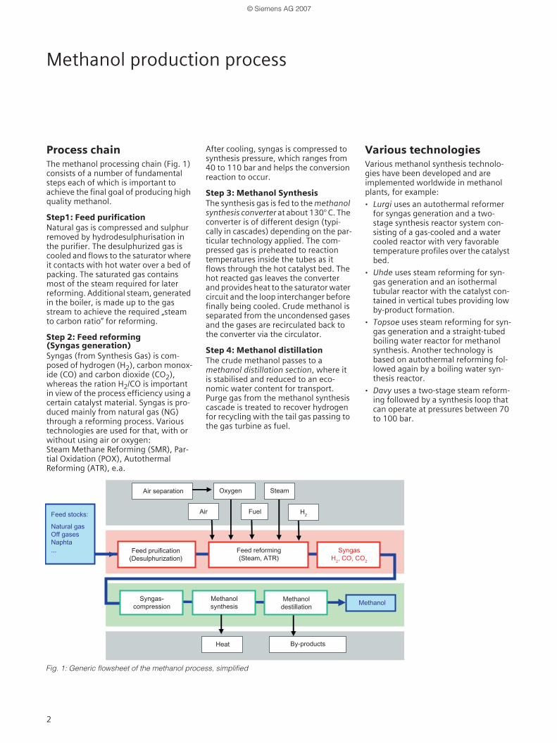
Process chainThe methanol processing chain (Fig. 1) consists of a number of fundamental steps each of which is important to achieve the final goal of producing high quality methanol.
Step1: Feed purification Natural gas is compressed and sulphur removed by hydrodesulphurisation in the purifier. The desulphurized gas is cooled and flows to the saturator where it contacts with hot water over a bed of packing. The saturated gas contains most of the steam required for later reforming. Additional steam, generated in the boiler, is made up to the gas stream to achieve the required „steam to carbon ratio“ for reforming.
Step 2: Feed reforming (Syngas generation) Syngas (from Synthesis Gas) is com-posed of hydrogen (H2), carbon monox-ide (CO) and carbon dioxide (CO2), whereas the ration H2/CO is important in view of the process efficiency using a certain catalyst material. Syngas is pro-duced mainly from natural gas (NG) through a reforming process. Various technologies are used for that, with or without using air or oxygen: Steam Methane Reforming (SMR), Par-tial Oxidation (POX), Autothermal Reforming (ATR), e.a.
After cooling, syngas is compressed to synthesis pressure, which ranges from 40 to 110 bar and helps the conversion reaction to occur.
Step 3: Methanol SynthesisThe synthesis gas is fed to the methanol synthesis converter at about 130° C. The converter is of different design (typi-cally in cascades) depending on the par-ticular technology applied. The com-pressed gas is preheated to reaction temperatures inside the tubes as it flows through the hot catalyst bed. The hot reacted gas leaves the converter and provides heat to the saturator water circuit and the loop interchanger before finally being cooled. Crude methanol is separated from the uncondensed gases and the gases are recirculated back to the converter via the circulator.
Step 4: Methanol distillation The crude methanol passes to a methanol distillation section, where it is stabilised and reduced to an eco-nomic water content for transport. Purge gas from the methanol synthesis cascade is treated to recover hydrogen for recycling with the tail gas passing to the gas turbine as fuel.
Various technologiesVarious methanol synthesis technolo-gies have been developed and are implemented worldwide in methanol plants, for example:
· Lurgi uses an autothermal reformer for syngas generation and a two-stage synthesis reactor system con-sisting of a gas-cooled and a water cooled reactor with very favorable temperature profiles over the catalyst bed.
· Uhde uses steam reforming for syn-gas generation and an isothermal tubular reactor with the catalyst con-tained in vertical tubes providing low by-product formation.
· Topsoe uses steam reforming for syn-gas generation and a straight-tubed boiling water reactor for methanol synthesis. Another technology is based on autothermal reforming fol-lowed again by a boiling water syn-thesis reactor.
· Davy uses a two-stage steam reform-ing followed by a synthesis loop that can operate at pressures between 70 to 100 bar.
Wärme
Fig. 1: Generic flowsheet of the methanol process, simplified
Feed pretreatmentNG is a mixture consisting primarily of hydrocarbons, but other gases are also present such as nitrogen, carbon diox-ide and sulfur compounds. In order to avoid poisoning of the catalyst material in the conversion process, the NG is first purified, mainly from sulfur, in a hydro-genation reactor and a washing system. After purification the feed gas is pre-treated (saturated with process conden-sate and process water and preheated) before being fed to the syngas genera-tion process.
Feed reforming(Syngas generation)Syngas can be made by various technol-ogies which require mostly steam and air or oxygen. During the feed (NG) reforming process, the hydrocarbon molecules are broken down and stripped of their hydrogen atoms. The carbon atoms together with oxygen, introduced as steam, air or as pure gas, form CO molecules. All reactions, inde-pendently of the technology applied, result in a gas consisting of H2, CO and CO2 called Synthesis Gas or Syngas.
Steam-Methane Reforming (SMR)In steam-methane reforming, the most widely used technology for syngas pro-duction, natural gas and steam are mixed and passed over a catalyst located in a firebox. Heat for the reac-tion is supplied by burning some of the feedstock gas. SMR does not require a separate air or oxygen supply from a oxygen plant.
Partial Oxidation Reforming (POX)The partial oxidation process is a direct non-catalytic reaction between oxygen and the hydrocarbon gas. It uses no steam and requires no catalyst. It is operated at very high temperatures of about 1400 °C and oxygen is needed.
Autothermal Reforming (ATR)Unlike POX, autothermal reforming uses a catalyst to reform NG to syngas in the presence of steam and oxygen. The reaction produces high temperatures and no additional heat source is needed („autothermal“). It produces syngas that
is suitable for most conversion pro-cesses. But an air separation plant is required.
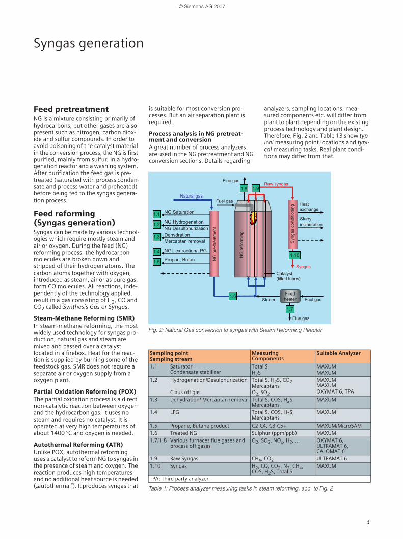
Process analysis in NG pretreat-ment and conversionA great number of process analyzers are used in the NG pretreatment and NG conversion sections. Details regarding
analyzers, sampling locations, mea-sured components etc. will differ from plant to plant depending on the existing process technology and plant design. Therefore, Fig. 2 and Table 13 show typ-ical measuring point locations and typi-cal measuring tasks. Real plant condi-tions may differ from that.
Table 1: Process analyzer measuring tasks in steam reforming, acc. to Fig. 2
Sampling point Sampling stream
MeasuringComponents
Suitable Analyzer
1.1 SaturatorCondensate stabilizer
Total SH2S
MAXUMMAXUM
1.2 Hydrogenation/Desulphurization
Claus off gas
Total S, H2S, CO2MercaptansO2, SO2
MAXUMMAXUMOXYMAT 6, TPA
1.3 Dehydration/ Mercaptan removal Total S, COS, H2S,Mercaptans
MAXUM
1.4 LPG Total S, COS, H2S,Mercaptans
MAXUM
1.5 Propane, Butane product C2-C4, C3-C5+ MAXUM/MicroSAM1.6 Treated NG Sulphur (ppm/ppb) MAXUM1.7/1.8 Various furnaces flue gases and
process off gasesO2, SO2, NOx, H2, ... OXYMAT 6,
ULTRAMAT 6,CALOMAT 6
1.9 Raw Syngas CH4, CO2 ULTRAMAT 61.10 Syngas H2, CO, CO2, N2, CH4,
COS, H2S, Total SMAXUM
TPA: Third party analyzer
Fuel gas
Catalyst filled tubes
Steam
Raw syngas
Natural GasHeat exchange
Flue gas
1.8
1.2NG Hydrogenation
NG Desulphurization
NG Saturation
Dehydration
Mercaptane removal
NGL extraction/LPG
NG
pre
-trea
tmen
t
1.3
1.4
Syng
asco
nditi
onin
g
Slurry incineration
Syngas
1.6
NG
refo
rmin
g
Firedheater
Flue gas
1.10
1.7
1.1
1.9
Fuel gas
Propane, Butane1.5
1.8
1.6
1.10
1.7
1.9
Fig. 2: Natural Gas conversion to syngas with Steam Reforming Reactor
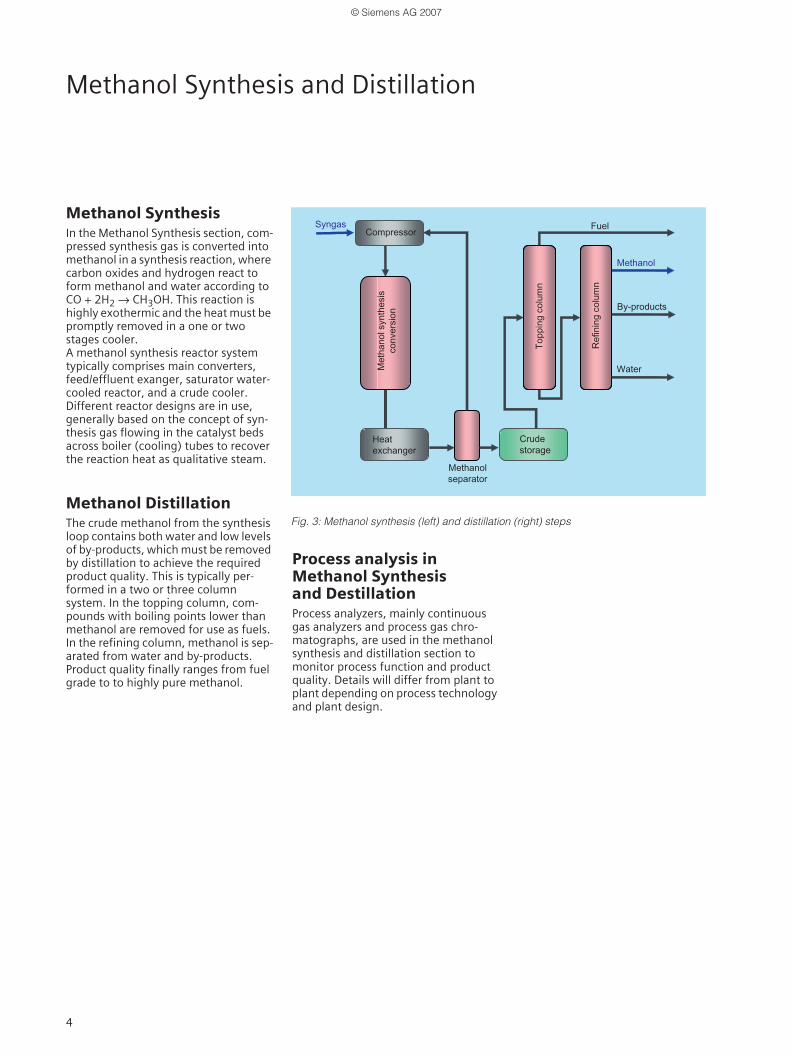
Methanol SynthesisIn the Methanol Synthesis section, com-pressed synthesis gas is converted into methanol in a synthesis reaction, where carbon oxides and hydrogen react to form methanol and water according to CO + 2H2 → CH3OH. This reaction is highly exothermic and the heat must be promptly removed in a one or two stages cooler. A methanol synthesis reactor system typically comprises main converters, feed/effluent exanger, saturator water-cooled reactor, and a crude cooler. Different reactor designs are in use, generally based on the concept of syn-thesis gas flowing in the catalyst beds across boiler (cooling) tubes to recover the reaction heat as qualitative steam.
Methanol DistillationThe crude methanol from the synthesis loop contains both water and low levels of by-products, which must be removed by distillation to achieve the required product quality. This is typically per-formed in a two or three column system. In the topping column, com-pounds with boiling points lower than methanol are removed for use as fuels. In the refining column, methanol is sep-arated from water and by-products. Product quality finally ranges from fuel grade to to highly pure methanol.
Process analysis in Methanol Synthesis and DestillationProcess analyzers, mainly continuous gas analyzers and process gas chro-matographs, are used in the methanol synthesis and distillation section to monitor process function and product quality. Details will differ from plant to plant depending on process technology and plant design.
Fig. 3: Methanol synthesis (left) and distillation (right) steps
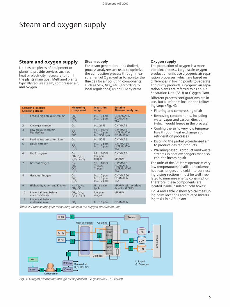
Steam and oxygen supplyUtilities are pieces of equipment or plants to provide services such as heat or electricity necessary to fulfill the plants main goal. Methanol plants typically require steam, compressed air, and oxygen.
Steam supplyFor steam generation units (boiler), process analyzers are used to optimize the combustion process through mea-surement of O2 as well as to monitor the flue gas for air polluting components such as SO2, NOx, etc. (according to local regulations) using CEM systems.
Oxygen supplyThe production of oxygen is a more complex process. Large-scale oxygen production units use cryogenic air sepa-ration processes, which are based on differences in boiling points to separate and purify products. Cryogenic air sepa-ration plants are referred to as an Air Separation Unit (ASU) or Oxygen Plant.
Different process configurations are in use, but all of them include the follow-ing steps (Fig. 4):
· Filtering and compressing of air
· Removing contaminants, including water vapor and carbon dioxide (which would freeze in the process)
· Cooling the air to very low tempera-ture through heat exchange and refrigeration processes
· Distilling the partially-condensed air to produce desired products
· Warming gaseous products and waste streams in heat exchangers that also cool the incoming air
The units of the ASU that operate at very low temperatures (distillation columns, heat exchangers and cold interconnect-ing piping sections) must be well insu-lated to minimize energy consumption. Therefore, these components are located inside insulated "cold boxes”.
Fig. 4 and Table 2 show typical measur-ing point locations and related measur-ing tasks in a ASU plant.
Table 2: Process analyzer measuring tasks in the oxygen production unit
Siemens Process AnalyticsSiemens Process Analytics is a leading provider of process analyzers and pro-cess analysis systems. We offer our glo-bal customers the best solutions for their applications based on innovative analysis technologies, customized sys-tem engineering, sound knowledge of customer applications and professional support. And with Totally Integrated Automation (TIA). Siemens Process Analytics is your qualified partner for efficient solutions that integrate pro-cess analysers into automations sys-tems in the process industry.
From demanding analysis tasks in the chemical, oil & gas and petrochemical industry to combustion control in power plants to emission monitoring at waste incineration plants, the highly accurate and reliable Siemens gas chro-matographs and continuous analysers will always do the job.
Siemens process Analytics offers a wide and innovative portfolio designed to meet all user requirements for compre-hensive products and solutions.
Our ProductsThe product line of Siemens Process Analytics comprises extractive and in-situ continuous gas analyzers (fig. 5 to 8), process gas chromatographs (fig. 9 to 12), sampling systems and auxiliary equipment. Analyzers and chromato-graphs are available in different ver-sions for rack or field mounting, explo-sion protection, corrosion resistant etc.
A flexible networking concept allows interfacing to DCS and maintenance stations via 4 to 20 mA, PROFIBUS,Modbus, OPC or industrial ethernet.
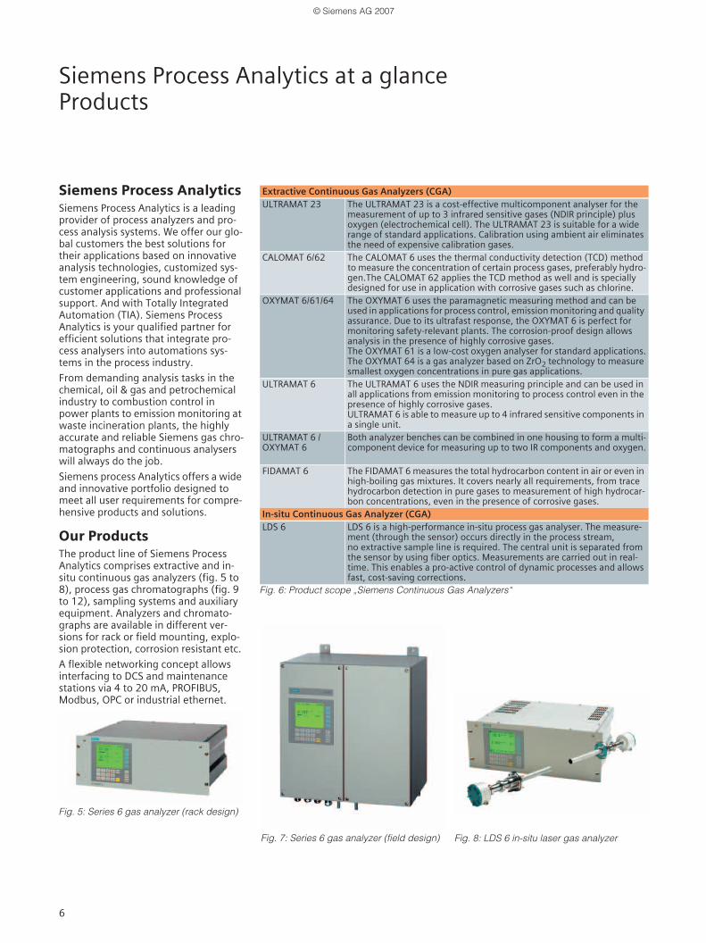
Fig. 5: Series 6 gas analyzer (rack design)
Fig. 6: Product scope „Siemens Continuous Gas Analyzers“
Extractive Continuous Gas Analyzers (CGA)ULTRAMAT 23 The ULTRAMAT 23 is a cost-effective multicomponent analyser for the
measurement of up to 3 infrared sensitive gases (NDIR principle) plusoxygen (electrochemical cell). The ULTRAMAT 23 is suitable for a wide range of standard applications. Calibration using ambient air eliminates the need of expensive calibration gases.
CALOMAT 6/62 The CALOMAT 6 uses the thermal conductivity detection (TCD) method to measure the concentration of certain process gases, preferably hydro-gen.The CALOMAT 62 applies the TCD method as well and is speciallydesigned for use in application with corrosive gases such as chlorine.
OXYMAT 6/61/64 The OXYMAT 6 uses the paramagnetic measuring method and can be used in applications for process control, emission monitoring and quality assurance. Due to its ultrafast response, the OXYMAT 6 is perfect for monitoring safety-relevant plants. The corrosion-proof design allows analysis in the presence of highly corrosive gases.The OXYMAT 61 is a low-cost oxygen analyser for standard applications.The OXYMAT 64 is a gas analyzer based on ZrO2 technology to measure smallest oxygen concentrations in pure gas applications.
ULTRAMAT 6 The ULTRAMAT 6 uses the NDIR measuring principle and can be used in all applications from emission monitoring to process control even in the presence of highly corrosive gases.ULTRAMAT 6 is able to measure up to 4 infrared sensitive components in a single unit.
ULTRAMAT 6 /OXYMAT 6
Both analyzer benches can be combined in one housing to form a multi-component device for measuring up to two IR components and oxygen.
FIDAMAT 6 The FIDAMAT 6 measures the total hydrocarbon content in air or even in high-boiling gas mixtures. It covers nearly all requirements, from trace hydrocarbon detection in pure gases to measurement of high hydrocar-bon concentrations, even in the presence of corrosive gases.
In-situ Continuous Gas Analyzer (CGA)LDS 6 LDS 6 is a high-performance in-situ process gas analyser. The measure-
ment (through the sensor) occurs directly in the process stream,no extractive sample line is required. The central unit is separated from the sensor by using fiber optics. Measurements are carried out in real-time. This enables a pro-active control of dynamic processes and allows fast, cost-saving corrections.
Fig. 7: Series 6 gas analyzer (field design) Fig. 8: LDS 6 in-situ laser gas analyzer
Siemens Process Analytics at a glanceProducts (continued) and Solutions
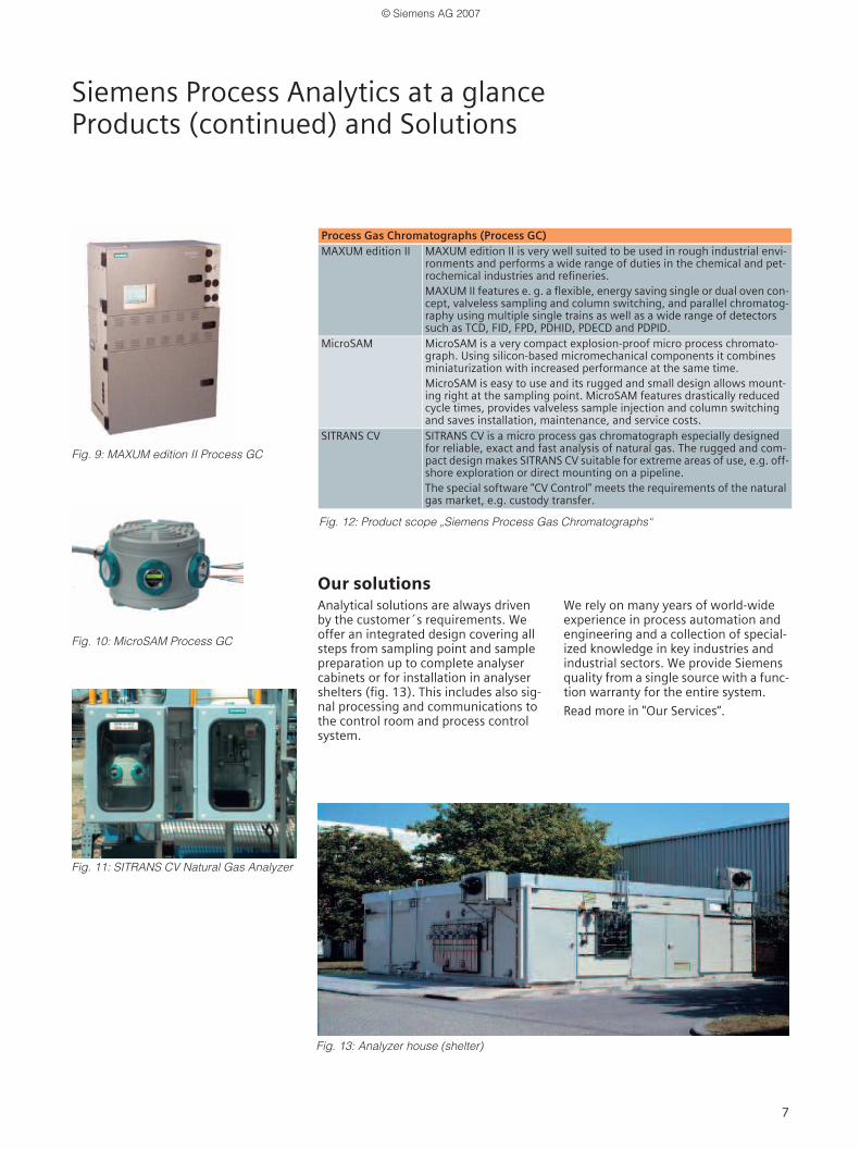
Fig. 9: MAXUM edition II Process GC
Fig. 10: MicroSAM Process GC
Fig. 11: SITRANS CV Natural Gas Analyzer
Our solutionsAnalytical solutions are always driven by the customer´s requirements. We offer an integrated design covering all steps from sampling point and sample preparation up to complete analyser cabinets or for installation in analyser shelters (fig. 13). This includes also sig-nal processing and communications to the control room and process control system.
We rely on many years of world-wide experience in process automation and engineering and a collection of special-ized knowledge in key industries and industrial sectors. We provide Siemens quality from a single source with a func-tion warranty for the entire system.
Read more in "Our Services“.
Fig. 13: Analyzer house (shelter)
Process Gas Chromatographs (Process GC) MAXUM edition II MAXUM edition II is very well suited to be used in rough industrial envi-
ronments and performs a wide range of duties in the chemical and pet-rochemical industries and refineries.MAXUM II features e. g. a flexible, energy saving single or dual oven con-cept, valveless sampling and column switching, and parallel chromatog-raphy using multiple single trains as well as a wide range of detectors such as TCD, FID, FPD, PDHID, PDECD and PDPID.
MicroSAM MicroSAM is a very compact explosion-proof micro process chromato-graph. Using silicon-based micromechanical components it combines miniaturization with increased performance at the same time.MicroSAM is easy to use and its rugged and small design allows mount-ing right at the sampling point. MicroSAM features drastically reduced cycle times, provides valveless sample injection and column switching and saves installation, maintenance, and service costs.
SITRANS CV SITRANS CV is a micro process gas chromatograph especially designed for reliable, exact and fast analysis of natural gas. The rugged and com-pact design makes SITRANS CV suitable for extreme areas of use, e.g. off-shore exploration or direct mounting on a pipeline.The special software "CV Control" meets the requirements of the natural gas market, e.g. custody transfer.
Fig. 12: Product scope „Siemens Process Gas Chromatographs“
Siemens Process Analytics at a glanceSolutions (continued) and Services
Our solutions ...
Analyzer networking fordata communication Engineering and manufacturing of pro-cess analytical solutions increasingly comprises "networking". It is getting a standard requirement in the process industry to connect analyzers andanalyzer systems to a communication network to provide for continuous and direct data transfer from and to the analysers.The two objectives are (fig. 15):
· To integrate the analyzer andanalyzer systems seamless into the PCS / DCS system of the plantand
· To allow direct access to the analyzers or systems from a maintenancestation to ensure correct and reliable operation including preventive orpredictive maintenance (fig.14).
Siemens Process Analytics provides net-working solutions to meet the demands of both objectives.
Our ServicesSiemens Process Analytics is your com-petent and reliable partner world wide for Service, Support and Consulting.
Our rescources for that are
· ExpertiseAs a manufacturer of a broad variety of analyzers, we are very much expe-rienced in engineering and manufac-turing of analytical systems and analyzer houses.We are familiar with communication networks, well trained in service and maintenance and familiar with many industrial pro cesses and industries.Thus, Siemens Process Analytics owns a unique blend of overall analytical expertise and experience.
· Global presenceWith our strategically located centers of competence in Germany, USA,Singapore, Dubai and Shanghai, we are globally present and acquainted with all respective local and regional requirements, codes and standards.All centers are networked together.
Fig. 15: Networking for DCS integration and maintenance support
Siemens Process Analytics at a glanceServices, continued
Our Services ...
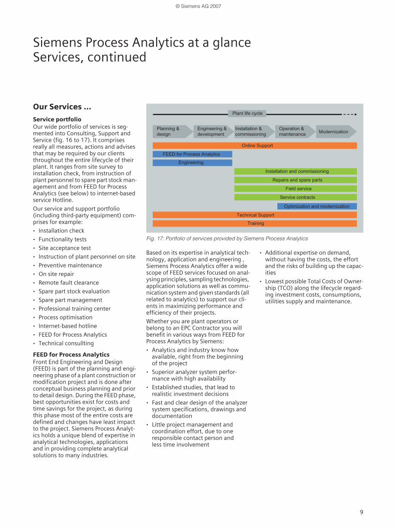
Service portfolio Our wide portfolio of services is seg-mented into Consulting, Support and Service (fig. 16 to 17). It comprises really all measures, actions and advises that may be required by our clients throughout the entire lifecycle of their plant. It ranges from site survey to installation check, from instruction of plant personnel to spare part stock man-agement and from FEED for Process Analytics (see below) to internet-based service Hotline.
Our service and support portfolio (including third-party equipment) com-prises for example:
· Installation check
· Functionality tests
· Site acceptance test
· Instruction of plant personnel on site
· Preventive maintenance
· On site repair
· Remote fault clearance
· Spare part stock evaluation
· Spare part management
· Professional training center
· Process optimisation
· Internet-based hotline
· FEED for Process Analytics
· Technical consullting
FEED for Process AnalyticsFront End Engineering and Design (FEED) is part of the planning and engi-neering phase of a plant construction or modification project and is done after conceptual business planning and prior to detail design. During the FEED phase, best opportunities exist for costs and time savings for the project, as during this phase most of the entire costs are defined and changes have least impact to the project. Siemens Process Analyt-ics holds a unique blend of expertise in analytical technologies, applications and in providing complete analytical solutions to many industries.
Based on its expertise in analytical tech-nology, application and engineering , Siemens Process Analytics offer a wide scope of FEED services focused on anal-ysing principles, sampling technologies, application solutions as well as commu-nication system and given standards (all related to analytics) to support our cli-ents in maximizing performance and efficiency of their projects.
Whether you are plant operators or belong to an EPC Contractor you will benefit in various ways from FEED for Process Analytics by Siemens:
· Analytics and industry know how available, right from the beginning of the project
· Superior analyzer system perfor-mance with high availability
· Established studies, that lead to realistic investment decisions
· Fast and clear design of the analyzer system specifications, drawings and documentation
· Little project management and coordination effort, due to one responsible contact person and less time involvement
· Additional expertise on demand, without having the costs, the effort and the risks of building up the capac-ities
· Lowest possible Total Costs of Owner-ship (TCO) along the lifecycle regard-ing investment costs, consumptions, utilities supply and maintenance.
Fig. 17: Portfolio of services provided by Siemens Process Analytics