Page 1
Method 315 8/7/2017
1
While we have taken steps to ensure the accuracy of this Internet version of the document, it is not the
official version. To see a complete version including any recent edits, visit:
https://www.ecfr.gov/cgi-bin/ECFR?page=browse and search under Title 40, Protection of
Environment.
METHOD 315—DETERMINATION OF PARTICULATE AND METHYLENE CHLORIDE
EXTRACTABLE MATTER (MCEM) FROM SELECTED SOURCES AT PRIMARY ALUMINUM
PRODUCTION FACILITIES
NOTE: This method does not include all of the specifications (e.g., equipment and supplies) and
procedures (e.g., sampling and analytical) essential to its performance. Some material is
incorporated by reference from other methods in this part. Therefore, to obtain reliable results,
persons using this method should have a thorough knowledge of at least the following additional
test methods: Method 1, Method 2, Method 3, and Method 5 of 40 CFR part 60, appendix A.
1.0 Scope and Application
1.1 Analytes. Particulate matter (PM). No CAS number assigned. Methylene chloride extractable
matter (MCEM). No CAS number assigned.
1.2 Applicability. This method is applicable for the simultaneous determination of PM and
MCEM when specified in an applicable regulation. This method was developed by consensus
with the Aluminum Association and the U.S. Environmental Protection Agency (EPA) and has
limited precision estimates for MCEM; it should have similar precision to Method 5 for PM in
40 CFR part 60, appendix A since the procedures are similar for PM.
1.3 Data quality objectives. Adherence to the requirements of this method will enhance the
quality of the data obtained from air pollutant sampling methods.
2.0 Summary of Method
Particulate matter and MCEM are withdrawn isokinetically from the source. PM is collected on a
glass fiber filter maintained at a temperature in the range of 120 ±14 °C (248 ±25 °F) or such
other temperature as specified by an applicable subpart of the standards or approved by the
Administrator for a particular application. The PM mass, which includes any material that
condenses on the probe and is subsequently removed in an acetone rinse or on the filter at or
above the filtration temperature, is determined gravimetrically after removal of uncombined
water. MCEM is then determined by adding a methylene chloride rinse of the probe and filter
holder, extracting the condensable hydrocarbons collected in the impinger water, adding an
acetone rinse followed by a methylene chloride rinse of the sampling train components after the
filter and before the silica gel impinger, and determining residue gravimetrically after
evaporating the solvents.
3.0 Definitions [Reserved]
4.0 Interferences [Reserved]
Page 2
Method 315 8/7/2017
2
5.0 Safety
This method may involve hazardous materials, operations, and equipment. This method does not
purport to address all of the safety problems associated with its use. It is the responsibility of the
user of this method to establish appropriate safety and health practices and determine the
applicability of regulatory limitations prior to performing this test method.
6.0 Equipment and Supplies
NOTE: Mention of trade names or specific products does not constitute endorsement by the EPA.
6.1 Sample collection. The following items are required for sample collection:
6.1.1 Sampling train. A schematic of the sampling train used in this method is shown in Figure
5-1, Method 5, 40 CFR part 60, appendix A-3. Complete construction details are given in APTD-
0581 (Reference 2 in section 17.0 of this method); commercial models of this train are also
available. For changes from APTD-0581 and for allowable modifications of the train shown in
Figure 5-1, Method 5, 40 CFR part 60, appendix A-3, see the following subsections.
NOTE: The operating and maintenance procedures for the sampling train are described in APTD-
0576 (Reference 3 in section 17.0 of this method). Since correct usage is important in obtaining
valid results, all users should read APTD-0576 and adopt the operating and maintenance
procedures outlined in it, unless otherwise specified herein. Alternative mercury-free
thermometers may be used if the thermometers are, at a minimum, equivalent in terms of
performance or suitably effective for the specific temperature measurement application. The use
of grease for sealing sampling train components is not recommended because many greases are
soluble in methylene chloride. The sampling train consists of the following components:
6.1.1.1 Probe nozzle. Glass or glass lined with sharp, tapered leading edge. The angle of taper
shall be ≤30 °, and the taper shall be on the outside to preserve a constant internal diameter. The
probe nozzle shall be of the button-hook or elbow design, unless otherwise specified by the
Administrator. Other materials of construction may be used, subject to the approval of the
Administrator. A range of nozzle sizes suitable for isokinetic sampling should be available.
Typical nozzle sizes range from 0.32 to 1.27 cm ( 1⁄8 to 1⁄2 in.) inside diameter (ID) in increments
of 0.16 cm (1/16 in.). Larger nozzle sizes are also available if higher volume sampling trains are
used. Each nozzle shall be calibrated according to the procedures outlined in section 10.0 of this
method.
6.1.1.2 Probe liner. Borosilicate or quartz glass tubing with a heating system capable of
maintaining a probe gas temperature at the exit end during sampling of 120 ±14 °C (248±25 °F),
or such other temperature as specified by an applicable subpart of the standards or approved by
the Administrator for a particular application. Because the actual temperature at the outlet of the
probe is not usually monitored during sampling, probes constructed according to APTD-0581
and using the calibration curves of APTD-0576 (or calibrated according to the procedure
outlined in APTD-0576) will be considered acceptable. Either borosilicate or quartz glass probe
liners may be used for stack temperatures up to about 480 °C (900 °F); quartz liners shall be used
for temperatures between 480 and 900 °C (900 and 1,650 °F). Both types of liners may be used
Page 3
Method 315 8/7/2017
3
at higher temperatures than specified for short periods of time, subject to the approval of the
Administrator. The softening temperature for borosilicate glass is 820 °C (1,500 °F) and for
quartz glass it is 1,500 °C (2,700 °F).
6.1.1.3 Pitot tube. Type S, as described in section 6.1 of Method 2, 40 CFR part 60, appendix A,
or other device approved by the Administrator. The pitot tube shall be attached to the probe (as
shown in Figure 5-1 of Method 5, 40 CFR part 60, appendix A) to allow constant monitoring of
the stack gas velocity. The impact (high pressure) opening plane of the pitot tube shall be even
with or above the nozzle entry plane (see Method 2, Figure 2-6b, 40 CFR part 60, appendix A)
during sampling. The Type S pitot tube assembly shall have a known coefficient, determined as
outlined in section 10.0 of Method 2, 40 CFR part 60, appendix A.
6.1.1.4 Differential pressure gauge. Inclined manometer or equivalent device (two), as described
in section 6.2 of Method 2, 40 CFR part 60, appendix A. One manometer shall be used for
velocity head (Dp) readings, and the other, for orifice differential pressure readings.
6.1.1.5 Filter holder. Borosilicate glass, with a glass frit filter support and a silicone rubber
gasket. The holder design shall provide a positive seal against leakage from the outside or around
the filter. The holder shall be attached immediately at the outlet of the probe (or cyclone, if
used).
6.1.1.6 Filter heating system. Any heating system capable of maintaining a temperature around
the filter holder of 120 ±14 °C (248 ±25 °F) during sampling, or such other temperature as
specified by an applicable subpart of the standards or approved by the Administrator for a
particular application. Alternatively, the tester may opt to operate the equipment at a temperature
lower than that specified. A temperature gauge capable of measuring temperature to within 3 °C
(5.4 °F) shall be installed so that the temperature around the filter holder can be regulated and
monitored during sampling. Heating systems other than the one shown in APTD-0581 may be
used.
6.1.1.7 Temperature sensor. A temperature sensor capable of measuring temperature to within ±3
°C (5.4 °F) shall be installed so that the sensing tip of the temperature sensor is in direct contact
with the sample gas, and the temperature around the filter holder can be regulated and monitored
during sampling.
6.1.1.8 Condenser. The following system shall be used to determine the stack gas moisture
content: four glass impingers connected in series with leak-free ground glass fittings. The first,
third, and fourth impingers shall be of the Greenburg-Smith design, modified by replacing the tip
with a 1.3 cm (1/2 in.) ID glass tube extending to about 1.3 cm (1/2 in.) from the bottom of the
flask. The second impinger shall be of the Greenburg-Smith design with the standard tip. The
first and second impingers shall contain known quantities of water (section 8.3.1 of this method),
the third shall be empty, and the fourth shall contain a known weight of silica gel or equivalent
desiccant. A temperature sensor capable of measuring temperature to within 1 °C (2 °F) shall be
placed at the outlet of the fourth impinger for monitoring.
Page 4
Method 315 8/7/2017
4
6.1.1.9 Metering system. Vacuum gauge, leak-free pump, temperature sensors capable of
measuring temperature to within 3 °C (5.4 °F), dry gas meter (DGM) capable of measuring
volume to within 2 percent, and related equipment, as shown in Figure 5-1 of Method 5, 40 CFR
part 60, appendix A. Other metering systems capable of maintaining sampling rates within 10
percent of isokinetic and of determining sample volumes to within 2 percent may be used,
subject to the approval of the Administrator. When the metering system is used in conjunction
with a pitot tube, the system shall allow periodic checks of isokinetic rates.
6.1.1.10 Sampling trains using metering systems designed for higher flow rates than that
described in APTD-0581 or APTD-0576 may be used provided that the specifications of this
method are met.
6.1.2 Barometer. Mercury, aneroid, or other barometer capable of measuring atmospheric
pressure to within 2.5 mm (0.1 in.) Hg.
NOTE: The barometric reading may be obtained from a nearby National Weather Service station.
In this case, the station value (which is the absolute barometric pressure) shall be requested and
an adjustment for elevation differences between the weather station and sampling point shall be
made at a rate of minus 2.5 mm (0.1 in) Hg per 30 m (100 ft) elevation increase or plus 2.5 mm
(0.1 in) Hg per 30 m (100 ft) elevation decrease.
6.1.3 Gas density determination equipment. Temperature sensor and pressure gauge, as described
in sections 6.3 and 6.4 of Method 2, 40 CFR part 60, appendix A, and gas analyzer, if necessary,
as described in Method 3, 40 CFR part 60, appendix A. The temperature sensor shall, preferably,
be permanently attached to the pitot tube or sampling probe in a fixed configuration, such that
the tip of the sensor extends beyond the leading edge of the probe sheath and does not touch any
metal. Alternatively, the sensor may be attached just prior to use in the field. Note, however, that
if the temperature sensor is attached in the field, the sensor must be placed in an interference-free
arrangement with respect to the Type S pitot tube openings (see Method 2, Figure 2-4, 40 CFR
part 60, appendix A). As a second alternative, if a difference of not more than 1 percent in the
average velocity measurement is to be introduced, the temperature sensor need not be attached to
the probe or pitot tube. (This alternative is subject to the approval of the Administrator.)
6.2 Sample recovery. The following items are required for sample recovery:
6.2.1 Probe-liner and probe-nozzle brushes. Nylon or Teflon® bristle brushes with stainless steel
wire handles. The probe brush shall have extensions (at least as long as the probe) constructed of
stainless steel, nylon, Teflon®, or similarly inert material. The brushes shall be properly sized and
shaped to brush out the probe liner and nozzle.
6.2.2 Wash bottles. Glass wash bottles are recommended. Polyethylene or tetrafluoroethylene
(TFE) wash bottles may be used, but they may introduce a positive bias due to contamination
from the bottle. It is recommended that acetone not be stored in polyethylene or TFE bottles for
longer than a month.
Page 5
Method 315 8/7/2017
5
6.2.3 Glass sample storage containers. Chemically resistant, borosilicate glass bottles, for
acetone and methylene chloride washes and impinger water, 500 ml or 1,000 ml. Screw-cap
liners shall either be rubber-backed Teflon® or shall be constructed so as to be leak-free and
resistant to chemical attack by acetone or methylene chloride. (Narrow-mouth glass bottles have
been found to be less prone to leakage.) Alternatively, polyethylene bottles may be used.
6.2.4 Petri dishes. For filter samples, glass, unless otherwise specified by the Administrator.
6.2.5 Graduated cylinder and/or balance. To measure condensed water, acetone wash and
methylene chloride wash used during field recovery of the samples, to within 1 ml or 1 g.
Graduated cylinders shall have subdivisions no greater than 2 ml. Most laboratory balances are
capable of weighing to the nearest 0.5 g or less. Any such balance is suitable for use here and in
section 6.3.4 of this method.
6.2.6 Plastic storage containers. Air-tight containers to store silica gel.
6.2.7 Funnel and rubber policeman. To aid in transfer of silica gel to container; not necessary if
silica gel is weighed in the field.
6.2.8 Funnel. Glass or polyethylene, to aid in sample recovery.
6.3 Sample analysis. The following equipment is required for sample analysis:
6.3.1 Glass or Teflon® weighing dishes.
6.3.2 Desiccator. It is recommended that fresh desiccant be used to minimize the chance for
positive bias due to absorption of organic material during drying.
6.3.3 Analytical balance. To measure to within 0.l mg.
6.3.4 Balance. To measure to within 0.5 g.
6.3.5 Beakers. 250 ml.
6.3.6 Hygrometer. To measure the relative humidity of the laboratory environment.
6.3.7 Temperature sensor. To measure the temperature of the laboratory environment.
6.3.8 Buchner fritted funnel. 30 ml size, fine (<50 micron)-porosity fritted glass.
6.3.9 Pressure filtration apparatus.
6.3.10 Aluminum dish. Flat bottom, smooth sides, and flanged top, 18 mm deep and with an
inside diameter of approximately 60 mm.
7.0 Reagents and Standards
Page 6
Method 315 8/7/2017
6
7.l Sample collection. The following reagents are required for sample collection:
7.1.1 Filters. Glass fiber filters, without organic binder, exhibiting at least 99.95 percent
efficiency (<0.05 percent penetration) on 0.3 micron dioctyl phthalate smoke particles. The filter
efficiency test shall be conducted in accordance with ASTM Method D 2986-95A (incorporated
by reference in §63.841 of this part). Test data from the supplier's quality control program are
sufficient for this purpose. In sources containing S02 or S03, the filter material must be of a type
that is unreactive to S02 or S03. Reference 10 in section 17.0 of this method may be used to select
the appropriate filter.
7.1.2 Silica gel. Indicating type, 6 to l6 mesh. If previously used, dry at l75 °C (350 °F) for 2
hours. New silica gel may be used as received. Alternatively, other types of desiccants
(equivalent or better) may be used, subject to the approval of the Administrator.
7.1.3 Water. When analysis of the material caught in the impingers is required, deionized
distilled water shall be used. Run blanks prior to field use to eliminate a high blank on test
samples.
7.1.4 Crushed ice.
7.1.5 Stopcock grease. Acetone-insoluble, heat-stable silicone grease. This is not necessary if
screw-on connectors with Teflon” sleeves, or similar, are used. Alternatively, other types of
stopcock grease may be used, subject to the approval of the Administrator. [Caution: Many
stopcock greases are methylene chloride-soluble. Use sparingly and carefully remove prior to
recovery to prevent contamination of the MCEM analysis.]
7.2 Sample recovery. The following reagents are required for sample recovery:
7.2.1 Acetone. Acetone with blank values <1 ppm, by weight residue, is required. Acetone
blanks may be run prior to field use, and only acetone with low blank values may be used. In no
case shall a blank value of greater than 1E-06 of the weight of acetone used be subtracted from
the sample weight.
NOTE: This is more restrictive than Method 5, 40 CFR part 60, appendix A. At least one vendor
(Supelco Incorporated located in Bellefonte, Pennsylvania) lists <1 mg/l as residue for its
Environmental Analysis Solvents.
7.2.2 Methylene chloride. Methylene chloride with a blank value <1.5 ppm, by weight, residue.
Methylene chloride blanks may be run prior to field use, and only methylene chloride with low
blank values may be used. In no case shall a blank value of greater than 1.6E-06 of the weight of
methylene chloride used be subtracted from the sample weight.
NOTE: A least one vendor quotes <1 mg/l for Environmental Analysis Solvents-grade methylene
chloride.
7.3 Sample analysis. The following reagents are required for sample analysis:
Page 7
Method 315 8/7/2017
7
7.3.l Acetone. Same as in section 7.2.1 of this method.
7.3.2 Desiccant. Anhydrous calcium sulfate, indicating type. Alternatively, other types of
desiccants may be used, subject to the approval of the Administrator.
7.3.3 Methylene chloride. Same as in section 7.2.2 of this method.
8.0 Sample Collection, Preservation, Storage, and Transport
NOTE: The complexity of this method is such that, in order to obtain reliable results, testers
should be trained and experienced with the test procedures.
8.1 Pretest preparation. It is suggested that sampling equipment be maintained according to the
procedures described in APTD-0576. Alternative mercury-free thermometers may be used if the
thermometers are at a minimum equivalent in terms of performance or suitably effective for the
specific temperature measurement application.
8.1.1 Weigh several 200 g to 300 g portions of silica gel in airtight containers to the nearest 0.5
g. Record on each container the total weight of the silica gel plus container. As an alternative, the
silica gel need not be preweighed but may be weighed directly in its impinger or sampling holder
just prior to train assembly.
8.1.2 A batch of glass fiber filters, no more than 50 at a time, should placed in a soxhlet
extraction apparatus and extracted using methylene chloride for at least 16 hours. After
extraction, check filters visually against light for irregularities, flaws, or pinhole leaks. Label the
shipping containers (glass or plastic petri dishes), and keep the filters in these containers at all
times except during sampling and weighing.
8.1.3 Desiccate the filters at 20 ±5.6 °C (68 ±10 °F) and ambient pressure for at least 24 hours
and weigh at intervals of at least 6 hours to a constant weight, i.e., <0.5 mg change from previous
weighing; record results to the nearest 0.1 mg. During each weighing the filter must not be
exposed to the laboratory atmosphere for longer than 2 minutes and a relative humidity above 50
percent. Alternatively (unless otherwise specified by the Administrator), the filters may be oven-
dried at 104 °C (220 °F) for 2 to 3 hours, desiccated for 2 hours, and weighed. Procedures other
than those described, which account for relative humidity effects, may be used, subject to the
approval of the Administrator.
8.2 Preliminary determinations.
8.2.1 Select the sampling site and the minimum number of sampling points according to Method
1, 40 CFR part 60, appendix A or as specified by the Administrator. Determine the stack
pressure, temperature, and the range of velocity heads using Method 2, 40 CFR part 60, appendix
A; it is recommended that a leak check of the pitot lines (see section 8.1 of Method 2, 40 CFR
part 60, appendix A) be performed. Determine the moisture content using Approximation
Method 4 (section 1.2 of Method 4, 40 CFR part 60, appendix A) or its alternatives to make
isokinetic sampling rate settings. Determine the stack gas dry molecular weight, as described in
section 8.6 of Method 2, 40 CFR part 60, appendix A; if integrated Method 3 sampling is used
Page 8
Method 315 8/7/2017
8
for molecular weight determination, the integrated bag sample shall be taken simultaneously
with, and for the same total length of time as, the particulate sample run.
8.2.2 Select a nozzle size based on the range of velocity heads such that it is not necessary to
change the nozzle size in order to maintain isokinetic sampling rates. During the run, do not
change the nozzle size. Ensure that the proper differential pressure gauge is chosen for the range
of velocity heads encountered (see section 8.2 of Method 2, 40 CFR part 60, appendix A).
8.2.3 Select a suitable probe liner and probe length such that all traverse points can be sampled.
For large stacks, consider sampling from opposite sides of the stack to reduce the required probe
length.
8.2.4 Select a total sampling time greater than or equal to the minimum total sampling time
specified in the test procedures for the specific industry such that: (1) The sampling time per
point is not less than 2 minutes (or some greater time interval as specified by the Administrator);
and (2) the sample volume taken (corrected to standard conditions) will exceed the required
minimum total gas sample volume. The latter is based on an approximate average sampling rate.
8.2.5 The sampling time at each point shall be the same. It is recommended that the number of
minutes sampled at each point be an integer or an integer plus one-half minute, in order to
eliminate timekeeping errors.
8.2.6 In some circumstances (e.g., batch cycles), it may be necessary to sample for shorter times
at the traverse points and to obtain smaller gas sample volumes. In these cases, the
Administrator's approval must first be obtained.
8.3 Preparation of sampling train.
8.3.1 During preparation and assembly of the sampling train, keep all openings where
contamination can occur covered until just prior to assembly or until sampling is about to begin.
Place l00 ml of water in each of the first two impingers, leave the third impinger empty, and
transfer approximately 200 to 300 g of preweighed silica gel from its container to the fourth
impinger. More silica gel may be used, but care should be taken to ensure that it is not entrained
and carried out from the impinger during sampling. Place the container in a clean place for later
use in the sample recovery. Alternatively, the weight of the silica gel plus impinger may be
determined to the nearest 0.5 g and recorded.
8.3.2 Using a tweezer or clean disposable surgical gloves, place a labeled (identified) and
weighed filter in the filter holder. Be sure that the filter is properly centered and the gasket
properly placed so as to prevent the sample gas stream from circumventing the filter. Check the
filter for tears after assembly is completed.
8.3.3 When glass liners are used, install the selected nozzle using a Viton A 0-ring when stack
temperatures are less than 260 °C (500 °F) and an asbestos string gasket when temperatures are
higher. See APTD-0576 for details. Mark the probe with heat-resistant tape or by some other
method to denote the proper distance into the stack or duct for each sampling point.
Page 9
Method 315 8/7/2017
9
8.3.4 Set up the train as in Figure 5-1 of Method 5, 40 CFR part 60, appendix A, using (if
necessary) a very light coat of silicone grease on all ground glass joints, greasing only the outer
portion (see APTD-0576) to avoid possibility of contamination by the silicone grease. Subject to
the approval of the Administrator, a glass cyclone may be used between the probe and filter
holder when the total particulate catch is expected to exceed 100 mg or when water droplets are
present in the stack gas.
8.3.5 Place crushed ice around the impingers.
8.4 Leak-check procedures.
8.4.1 Leak check of metering system shown in Figure 5-1 of Method 5, 40 CFR part 60,
appendix A. That portion of the sampling train from the pump to the orifice meter should be
leak-checked prior to initial use and after each shipment. Leakage after the pump will result in
less volume being recorded than is actually sampled. The following procedure is suggested (see
Figure 5-2 of Method 5, 40 CFR part 60, appendix A): Close the main valve on the meter box.
Insert a one-hole rubber stopper with rubber tubing attached into the orifice exhaust pipe.
Disconnect and vent the low side of the orifice manometer. Close off the low side orifice tap.
Pressurize the system to 13 to 18 cm (5 to 7 in.) water column by blowing into the rubber tubing.
Pinch off the tubing, and observe the manometer for 1 minute. A loss of pressure on the
manometer indicates a leak in the meter box; leaks, if present, must be corrected.
8.4.2 Pretest leak check. A pretest leak-check is recommended but not required. If the pretest
leak-check is conducted, the following procedure should be used.
8.4.2.1 After the sampling train has been assembled, turn on and set the filter and probe heating
systems to the desired operating temperatures. Allow time for the temperatures to stabilize. If a
Viton A 0-ring or other leak-free connection is used in assembling the probe nozzle to the probe
liner, leak-check the train at the sampling site by plugging the nozzle and pulling a 380 mm (15
in.) Hg vacuum.
NOTE: A lower vacuum may be used, provided that it is not exceeded during the test.
8.4.2.2 If an asbestos string is used, do not connect the probe to the train during the leak check.
Instead, leak-check the train by first plugging the inlet to the filter holder (cyclone, if applicable)
and pulling a 380 mm (15 in.) Hg vacuum. (See NOTE in section 8.4.2.1 of this method). Then
connect the probe to the train and perform the leak check at approximately 25 mm (1 in.) Hg
vacuum; alternatively, the probe may be leak-checked with the rest of the sampling train, in one
step, at 380 mm (15 in.) Hg vacuum. Leakage rates in excess of 4 percent of the average
sampling rate or 0.00057 m3/min (0.02 cfm), whichever is less, are unacceptable.
8.4.2.3 The following leak check instructions for the sampling train described in APTD-0576 and
APTD-058l may be helpful. Start the pump with the bypass valve fully open and the coarse
adjust valve completely closed. Partially open the coarse adjust valve and slowly close the
bypass valve until the desired vacuum is reached. Do not reverse the direction of the bypass
Page 10
Method 315 8/7/2017
10
valve, as this will cause water to back up into the filter holder. If the desired vacuum is exceeded,
either leak-check at this higher vacuum or end the leak check as shown below and start over.
8.4.2.4 When the leak check is completed, first slowly remove the plug from the inlet to the
probe, filter holder, or cyclone (if applicable) and immediately turn off the vacuum pump. This
prevents the water in the impingers from being forced backward into the filter holder and the
silica gel from being entrained backward into the third impinger.
8.4.3 Leak checks during sample run. If, during the sampling run, a component (e.g., filter
assembly or impinger) change becomes necessary, a leak check shall be conducted immediately
before the change is made. The leak check shall be done according to the procedure outlined in
section 8.4.2 of this method, except that it shall be done at a vacuum equal to or greater than the
maximum value recorded up to that point in the test. If the leakage rate is found to be no greater
than 0.00057 m3/min (0.02 cfm) or 4 percent of the average sampling rate (whichever is less), the
results are acceptable, and no correction will need to be applied to the total volume of dry gas
metered; if, however, a higher leakage rate is obtained, either record the leakage rate and plan to
correct the sample volume as shown in section 12.3 of this method or void the sample run.
NOTE: Immediately after component changes, leak checks are optional; if such leak checks are
done, the procedure outlined in section 8.4.2 of this method should be used.
8.4.4 Post-test leak check. A leak check is mandatory at the conclusion of each sampling run.
The leak check shall be performed in accordance with the procedures outlined in section 8.4.2 of
this method, except that it shall be conducted at a vacuum equal to or greater than the maximum
value reached during the sampling run. If the leakage rate is found to be no greater than 0.00057
m3/min (0.02 cfm) or 4 percent of the average sampling rate (whichever is less), the results are
acceptable, and no correction need be applied to the total volume of dry gas metered. If,
however, a higher leakage rate is obtained, either record the leakage rate and correct the sample
volume, as shown in section 12.4 of this method, or void the sampling run.
8.5 Sampling train operation. During the sampling run, maintain an isokinetic sampling rate
(within l0 percent of true isokinetic unless otherwise specified by the Administrator) and a
temperature around the filter of 120 14 °C (248 25 °F), or such other temperature as specified by
an applicable subpart of the standards or approved by the Administrator.
8.5.1 For each run, record the data required on a data sheet such as the one shown in Figure 5-2
of Method 5, 40 CFR part 60, appendix A. Be sure to record the initial reading. Record the DGM
readings at the beginning and end of each sampling time increment, when changes in flow rates
are made, before and after each leak-check, and when sampling is halted. Take other readings
indicated by Figure 5-2 of Method 5, 40 CFR part 60, appendix A at least once at each sample
point during each time increment and additional readings when significant changes (20 percent
variation in velocity head readings) necessitate additional adjustments in flow rate. Level and
zero the manometer. Because the manometer level and zero may drift due to vibrations and
temperature changes, make periodic checks during the traverse.
Page 11
Method 315 8/7/2017
11
8.5.2 Clean the portholes prior to the test run to minimize the chance of sampling deposited
material. To begin sampling, remove the nozzle cap and verify that the filter and probe heating
systems are up to temperature and that the pitot tube and probe are properly positioned. Position
the nozzle at the first traverse point with the tip pointing directly into the gas stream.
Immediately start the pump and adjust the flow to isokinetic conditions. Nomographs are
available, which aid in the rapid adjustment of the isokinetic sampling rate without excessive
computations. These nomographs are designed for use when the Type S pitot tube coefficient
(Cp) is 0.85 # 0.02 and the stack gas equivalent density (dry molecular weight) is 29 ±4. APTD-
0576 details the procedure for using the nomographs. If Cp and Md are outside the above-stated
ranges, do not use the nomographs unless appropriate steps (see Reference 7 in section 17.0 of
this method) are taken to compensate for the deviations.
8.5.3 When the stack is under significant negative pressure (height of impinger stem), close the
coarse adjust valve before inserting the probe into the stack to prevent water from backing into
the filter holder. If necessary, the pump may be turned on with the coarse adjust valve closed.
8.5.4 When the probe is in position, block off the openings around the probe and porthole to
prevent unrepresentative dilution of the gas stream.
8.5.5 Traverse the stack cross-section, as required by Method 1, 40 CFR part 60, appendix A or
as specified by the Administrator, being careful not to bump the probe nozzle into the stack walls
when sampling near the walls or when removing or inserting the probe through the portholes;
this minimizes the chance of extracting deposited material.
8.5.6 During the test run, make periodic adjustments to keep the temperature around the filter
holder at the proper level; add more ice and, if necessary, salt to maintain a temperature of less
than 20 °C (68 °F) at the condenser/silica gel outlet. Also, periodically check the level and zero
of the manometer.
8.5.7 If the pressure drop across the filter becomes too high, making isokinetic sampling difficult
to maintain, the filter may be replaced in the midst of the sample run. It is recommended that
another complete filter assembly be used rather than attempting to change the filter itself. Before
a new filter assembly is installed, conduct a leak check (see section 8.4.3 of this method). The
total PM weight shall include the summation of the filter assembly catches.
8.5.8 A single train shall be used for the entire sample run, except in cases where simultaneous
sampling is required in two or more separate ducts or at two or more different locations within
the same duct, or in cases where equipment failure necessitates a change of trains. In all other
situations, the use of two or more trains will be subject to the approval of the Administrator.
NOTE: When two or more trains are used, separate analyses of the front-half and (if applicable)
impinger catches from each train shall be performed, unless identical nozzle sizes were used in
all trains, in which case the front-half catches from the individual trains may be combined (as
may the impinger catches) and one analysis of the front-half catch and one analysis of the
impinger catch may be performed.
Page 12
Method 315 8/7/2017
12
8.5.9 At the end of the sample run, turn off the coarse adjust valve, remove the probe and nozzle
from the stack, turn off the pump, record the final DGM reading, and then conduct a post-test
leak check, as outlined in section 8.4.4 of this method. Also leak-check the pitot lines as
described in section 8.1 of Method 2, 40 CFR part 60, appendix A. The lines must pass this leak
check in order to validate the velocity head data.
8.6 Calculation of percent isokinetic. Calculate percent isokinetic (see Calculations, section
12.12 of this method) to determine whether a run was valid or another test run should be made. If
there was difficulty in maintaining isokinetic rates because of source conditions, consult the
Administrator for possible variance on the isokinetic rates.
8.7 Sample recovery.
8.7.1 Proper cleanup procedure begins as soon as the probe is removed from the stack at the end
of the sampling period. Allow the probe to cool.
8.7.2 When the probe can be safely handled, wipe off all external PM near the tip of the probe
nozzle and place a cap over it to prevent losing or gaining PM. Do not cap off the probe tip
tightly while the sampling train is cooling down. This would create a vacuum in the filter holder,
thus drawing water from the impingers into the filter holder.
8.7.3 Before moving the sample train to the cleanup site, remove the probe from the sample train,
wipe off the silicone grease, and cap the open outlet of the probe. Be careful not to lose any
condensate that might be present. Wipe off the silicone grease from the filter inlet where the
probe was fastened and cap it. Remove the umbilical cord from the last impinger and cap the
impinger. If a flexible line is used between the first impinger or condenser and the filter holder,
disconnect the line at the filter holder and let any condensed water or liquid drain into the
impingers or condenser. After wiping off the silicone grease, cap off the filter holder outlet and
impinger inlet. Ground-glass stoppers, plastic caps, or serum caps may be used to close these
openings.
8.7.4 Transfer the probe and filter-impinger assembly to the cleanup area. This area should be
clean and protected from the wind so that the chances of contaminating or losing the sample will
be minimized.
8.7.5 Save a portion of the acetone and methylene chloride used for cleanup as blanks. Take 200
ml of each solvent directly from the wash bottle being used and place it in glass sample
containers labeled “acetone blank” and “methylene chloride blank,” respectively.
8.7.6 Inspect the train prior to and during disassembly and note any abnormal conditions. Treat
the samples as follows:
8.7.6.1 Container No. 1. Carefully remove the filter from the filter holder, and place it in its
identified petri dish container. Use a pair of tweezers and/or clean disposable surgical gloves to
handle the filter. If it is necessary to fold the filter, do so such that the PM cake is inside the fold.
Page 13
Method 315 8/7/2017
13
Using a dry nylon bristle brush and/or a sharp-edged blade, carefully transfer to the petri dish
any PM and/or filter fibers that adhere to the filter holder gasket. Seal the container.
8.7.6.2 Container No. 2. Taking care to see that dust on the outside of the probe or other exterior
surfaces does not get into the sample, quantitatively recover PM or any condensate from the
probe nozzle, probe fitting, probe liner, and front half of the filter holder by washing these
components with acetone and placing the wash in a glass container. Perform the acetone rinse as
follows:
8.7.6.2.1 Carefully remove the probe nozzle and clean the inside surface by rinsing with acetone
from a wash bottle and brushing with a nylon bristle brush. Brush until the acetone rinse shows
no visible particles, after which make a final rinse of the inside surface with acetone.
8.7.6.2.2 Brush and rinse the inside parts of the Swagelok fitting with acetone in a similar way
until no visible particles remain.
8.7.6.2.3 Rinse the probe liner with acetone by tilting and rotating the probe while squirting
acetone into its upper end so that all inside surfaces are wetted with acetone. Let the acetone
drain from the lower end into the sample container. A funnel (glass or polyethylene) may be used
to aid in transferring liquid washes to the container. Follow the acetone rinse with a probe brush.
Hold the probe in an inclined position, squirt acetone into the upper end as the probe brush is
being pushed with a twisting action through the probe, hold a sample container under the lower
end of the probe, and catch any acetone and PM that is brushed from the probe. Run the brush
through the probe three times or more until no visible PM is carried out with the acetone or until
none remains in the probe liner on visual inspection. With stainless steel or other metal probes,
run the brush through in the above-described manner at least six times, since metal probes have
small crevices in which PM can be entrapped. Rinse the brush with acetone and quantitatively
collect these washings in the sample container. After the brushing, make a final acetone rinse of
the probe as described above.
8.7.6.2.4 It is recommended that two people clean the probe to minimize sample losses. Between
sampling runs, keep brushes clean and protected from contamination.
8.7.6.2.5 After ensuring that all joints have been wiped clean of silicone grease, clean the inside
of the front half of the filter holder by rubbing the surfaces with a nylon bristle brush and rinsing
with acetone. Rinse each surface three times or more if needed to remove visible particulate.
Make a final rinse of the brush and filter holder. Carefully rinse out the glass cyclone also (if
applicable).
8.7.6.2.6 After rinsing the nozzle, probe, and front half of the filter holder with acetone, repeat
the entire procedure with methylene chloride and save in a separate No. 2M container.
8.7.6.2.7 After acetone and methylene chloride washings and PM have been collected in the
proper sample containers, tighten the lid on the sample containers so that acetone and methylene
chloride will not leak out when it is shipped to the laboratory. Mark the height of the fluid level
Page 14
Method 315 8/7/2017
14
to determine whether leakage occurs during transport. Label each container to identify clearly its
contents.
8.7.6.3 Container No. 3. Note the color of the indicating silica gel to determine whether it has
been completely spent, and make a notation of its condition. Transfer the silica gel from the
fourth impinger to its original container and seal the container. A funnel may make it easier to
pour the silica gel without spilling. A rubber policeman may be used as an aid in removing the
silica gel from the impinger. It is not necessary to remove the small amount of dust particles that
may adhere to the impinger wall and are difficult to remove. Since the gain in weight is to be
used for moisture calculations, do not use any water or other liquids to transfer the silica gel. If a
balance is available in the field, follow the procedure for Container No. 3 in section 11.2.3 of this
method.
8.7.6.4 Impinger water. Treat the impingers as follows:
8.7.6.4.1 Make a notation of any color or film in the liquid catch. Measure the liquid that is in the
first three impingers to within 1 ml by using a graduated cylinder or by weighing it to within 0.5
g by using a balance (if one is available). Record the volume or weight of liquid present. This
information is required to calculate the moisture content of the effluent gas.
8.7.6.4.2 Following the determination of the volume of liquid present, rinse the back half of the
train with water, add it to the impinger catch, and store it in a container labeled 3W (water).
8.7.6.4.3 Following the water rinse, rinse the back half of the train with acetone to remove the
excess water to enhance subsequent organic recovery with methylene chloride and quantitatively
recover to a container labeled 3S (solvent) followed by at least three sequential rinsings with
aliquots of methylene chloride. Quantitatively recover to the same container labeled 3S. Record
separately the amount of both acetone and methylene chloride used to the nearest 1 ml or 0.5g.
NOTE: Because the subsequent analytical finish is gravimetric, it is okay to recover both solvents
to the same container. This would not be recommended if other analytical finishes were required.
8.8 Sample transport. Whenever possible, containers should be shipped in such a way that they
remain upright at all times.
9.0 Quality Control
9.1 Miscellaneous quality control measures.
Section Quality control measure Effect
8.4, 10.1-
10.6
Sampling and equipment leak check
and calibration
Ensure accurate measurement of stack gas flow
rate, sample volume.
Page 15
Method 315 8/7/2017
15
9.2 Volume metering system checks. The following quality control procedures are suggested to
check the volume metering system calibration values at the field test site prior to sample
collection. These procedures are optional.
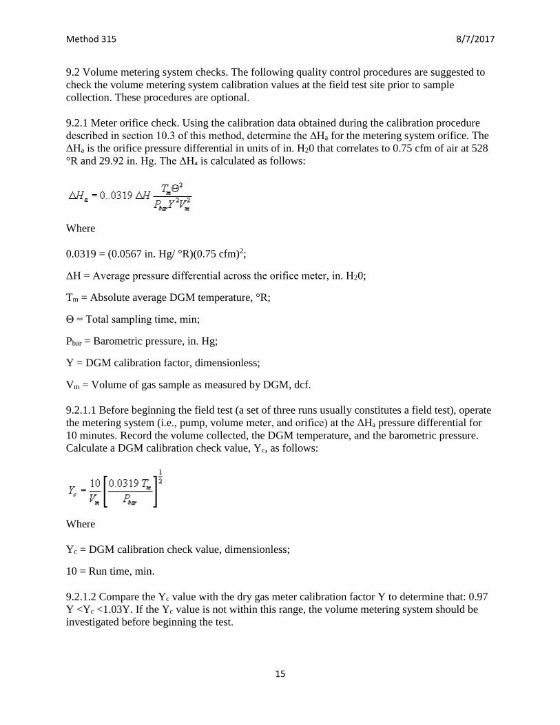
9.2.1 Meter orifice check. Using the calibration data obtained during the calibration procedure
described in section 10.3 of this method, determine the ΔHa for the metering system orifice. The
ΔHa is the orifice pressure differential in units of in. H20 that correlates to 0.75 cfm of air at 528
°R and 29.92 in. Hg. The ΔHa is calculated as follows:
Where
0.0319 = (0.0567 in. Hg/ °R)(0.75 cfm)2;
ΔH = Average pressure differential across the orifice meter, in. H20;
Tm = Absolute average DGM temperature, °R;
Θ = Total sampling time, min;
Pbar = Barometric pressure, in. Hg;
Y = DGM calibration factor, dimensionless;
Vm = Volume of gas sample as measured by DGM, dcf.
9.2.1.1 Before beginning the field test (a set of three runs usually constitutes a field test), operate
the metering system (i.e., pump, volume meter, and orifice) at the ΔHa pressure differential for
10 minutes. Record the volume collected, the DGM temperature, and the barometric pressure.
Calculate a DGM calibration check value, Yc, as follows:
Where
Yc = DGM calibration check value, dimensionless;
10 = Run time, min.
9.2.1.2 Compare the Yc value with the dry gas meter calibration factor Y to determine that: 0.97
Y <Yc <1.03Y. If the Yc value is not within this range, the volume metering system should be
investigated before beginning the test.
Page 16
Method 315 8/7/2017
16
9.2.2 Calibrated critical orifice. A calibrated critical orifice, calibrated against a wet test meter or
spirometer and designed to be inserted at the inlet of the sampling meter box, may be used as a
quality control check by following the procedure of section 16.2 of this method.
10.0 Calibration and Standardization
NOTE: Maintain a laboratory log of all calibrations.
10.1 Probe nozzle. Probe nozzles shall be calibrated before their initial use in the field. Using a
micrometer, measure the ID of the nozzle to the nearest 0.025 mm (0.001 in.). Make three
separate measurements using different diameters each time, and obtain the average of the
measurements. The difference between the high and low numbers shall not exceed 0.1 mm
(0.004 in.). When nozzles become nicked, dented, or corroded, they shall be reshaped,
sharpened, and recalibrated before use. Each nozzle shall be permanently and uniquely
identified.
10.2 Pitot tube assembly. The Type S pitot tube assembly shall be calibrated according to the
procedure outlined in section 10.1 of Method 2, 40 CFR part 60, appendix A.
10.3 Metering system.
10.3.1 Calibration prior to use. Before its initial use in the field, the metering system shall be
calibrated as follows: Connect the metering system inlet to the outlet of a wet test meter that is
accurate to within 1 percent. Refer to Figure 5-5 of Method 5, 40 CFR part 60, appendix A. The
wet test meter should have a capacity of 30 liters/revolution (1 ft3/rev). A spirometer of 400 liters
(14 ft3) or more capacity, or equivalent, may be used for this calibration, although a wet test
meter is usually more practical. The wet test meter should be periodically calibrated with a
spirometer or a liquid displacement meter to ensure the accuracy of the wet test meter.
Spirometers or wet test meters of other sizes may be used, provided that the specified accuracies
of the procedure are maintained. Run the metering system pump for about 15 minutes with the
orifice manometer indicating a median reading, as expected in field use, to allow the pump to
warm up and to permit the interior surface of the wet test meter to be thoroughly wetted. Then, at
each of a minimum of three orifice manometer settings, pass an exact quantity of gas through the
wet test meter and note the gas volume indicated by the DGM. Also note the barometric pressure
and the temperatures of the wet test meter, the inlet of the DGM, and the outlet of the DGM.
Select the highest and lowest orifice settings to bracket the expected field operating range of the
orifice. Use a minimum volume of 0.15 m3 (5 cf) at all orifice settings. Record all the data on a
form similar to Figure 5-6 of Method 5, 40 CFR part 60, appendix A, and calculate Y (the DGM
calibration factor) and ΔHa (the orifice calibration factor) at each orifice setting, as shown on
Figure 5-6 of Method 5, 40 CFR part 60, appendix A. Allowable tolerances for individual Y and
ΔHa values are given in Figure 5-6 of Method 5, 40 CFR part 60, appendix A. Use the average of
the Y values in the calculations in section 12 of this method.
10.3.1.1 Before calibrating the metering system, it is suggested that a leak check be conducted.
For metering systems having diaphragm pumps, the normal leak check procedure will not detect
leakages within the pump. For these cases the following leak check procedure is suggested: make
a 10-minute calibration run at 0.00057 m3/min (0.02 cfm); at the end of the run, take the
Page 17
Method 315 8/7/2017
17
difference of the measured wet test meter and DGM volumes; divide the difference by 10 to get
the leak rate. The leak rate should not exceed 0.00057 m3/min (0.02 cfm).
10.3.2 Calibration after use. After each field use, the calibration of the metering system shall be
checked by performing three calibration runs at a single, intermediate orifice setting (based on
the previous field test) with the vacuum set at the maximum value reached during the test series.
To adjust the vacuum, insert a valve between the wet test meter and the inlet of the metering
system. Calculate the average value of the DGM calibration factor. If the value has changed by
more than 5 percent, recalibrate the meter over the full range of orifice settings, as previously
detailed.
NOTE: Alternative procedures, e.g., rechecking the orifice meter coefficient, may be used, subject
to the approval of the Administrator.
10.3.3 Acceptable variation in calibration. If the DGM coefficient values obtained before and
after a test series differ by more than 5 percent, either the test series shall be voided or
calculations for the test series shall be performed using whichever meter coefficient value (i.e.,
before or after) gives the lower value of total sample volume.
10.4 Probe heater calibration. Use a heat source to generate air heated to selected temperatures
that approximate those expected to occur in the sources to be sampled. Pass this air through the
probe at a typical sample flow rate while measuring the probe inlet and outlet temperatures at
various probe heater settings. For each air temperature generated, construct a graph of probe
heating system setting versus probe outlet temperature. The procedure outlined in APTD-0576
can also be used. Probes constructed according to APTD-0581 need not be calibrated if the
calibration curves in APTD-0576 are used. Also, probes with outlet temperature monitoring
capabilities do not require calibration.
NOTE: The probe heating system shall be calibrated before its initial use in the field.
10.5 Temperature sensors. Use the procedure in Section 10.3 of Method 2, 40 CFR part 60,
appendix A-1 to calibrate in-stack temperature sensors. Dial thermometers, such as are used for
the DGM and condenser outlet, shall be calibrated against mercury-in-glass thermometers. An
alternative mercury-free thermometer may be used if the thermometer is, at a minimum,
equivalent in terms of performance or suitably effective for the specific temperature
measurement application.
10.6 Barometer. Calibrate against a mercury barometer.
11.0 Analytical Procedure
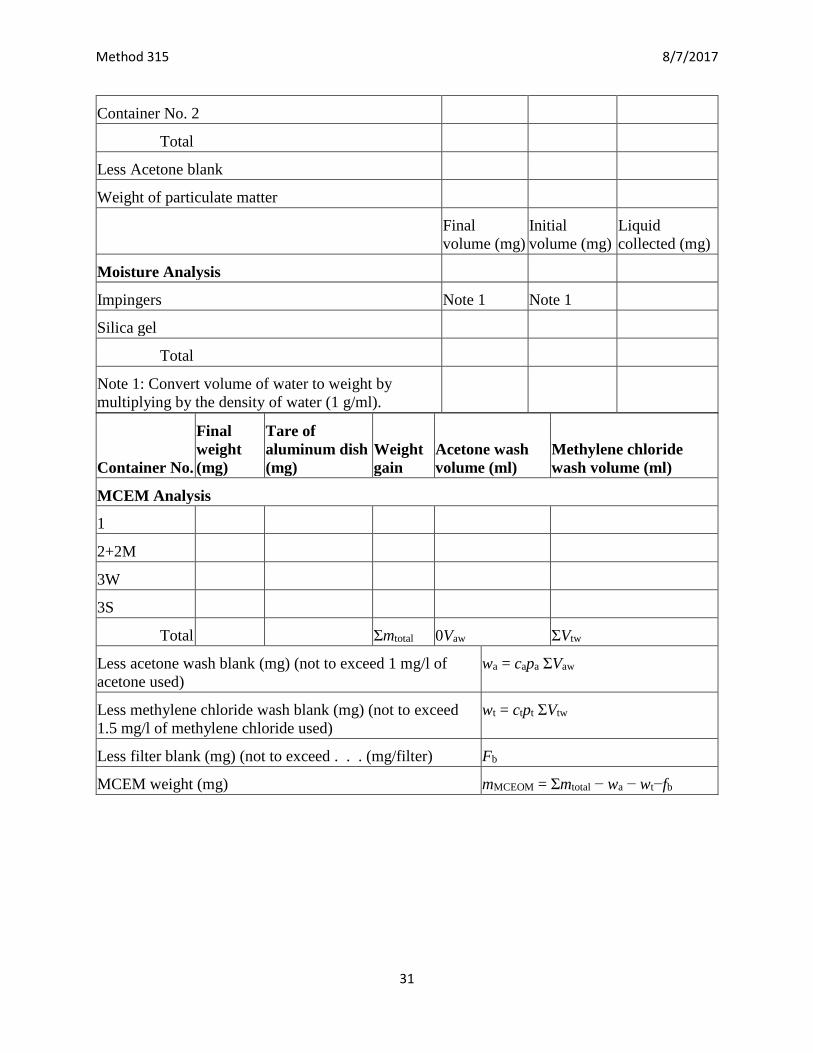
11.1 Record the data required on a sheet such as the one shown in Figure 315-1 of this method.
11.2 Handle each sample container as follows:
11.2.1 Container No. 1.
Page 18
Method 315 8/7/2017
18
11.2.1.1 PM analysis. Leave the contents in the shipping container or transfer the filter and any
loose PM from the sample container to a tared glass weighing dish. Desiccate for 24 hours in a
desiccator containing anhydrous calcium sulfate. Weigh to a constant weight and report the
results to the nearest 0.1 mg. For purposes of this section, the term “constant weight” means a
difference of no more than 0.5 mg or 1 percent of total weight less tare weight, whichever is
greater, between two consecutive weighings, with no less than 6 hours of desiccation time
between weighings (overnight desiccation is a common practice). If a third weighing is required
and it agrees within ±0.5 mg, then the results of the second weighing should be used. For quality
assurance purposes, record and report each individual weighing; if more than three weighings are
required, note this in the results for the subsequent MCEM results.
11.2.1.2 MCEM analysis. Transfer the filter and contents quantitatively into a beaker. Add 100
ml of methylene chloride and cover with aluminum foil. Sonicate for 3 minutes then allow to
stand for 20 minutes. Set up the filtration apparatus. Decant the solution into a clean Buchner
fritted funnel. Immediately pressure filter the solution through the tube into another clean, dry
beaker. Continue decanting and pressure filtration until all the solvent is transferred. Rinse the
beaker and filter with 10 to 20 ml methylene chloride, decant into the Buchner fritted funnel and
pressure filter. Place the beaker on a low-temperature hot plate (maximum 40 °C) and slowly
evaporate almost to dryness. Transfer the remaining last few milliliters of solution quantitatively
from the beaker (using at least three aliquots of methylene chloride rinse) to a tared clean dry
aluminum dish and evaporate to complete dryness. Remove from heat once solvent is
evaporated. Reweigh the dish after a 30-minute equilibrium in the balance room and determine
the weight to the nearest 0.1 mg. Conduct a methylene chloride blank run in an identical fashion.
11.2.2 Container No. 2.
11.2.2.1 PM analysis. Note the level of liquid in the container, and confirm on the analysis sheet
whether leakage occurred during transport. If a noticeable amount of leakage has occurred, either
void the sample or use methods, subject to the approval of the Administrator, to correct the final
results. Measure the liquid in this container either volumetrically to ±1 ml or gravimetrically to 1
±0.5 g. Transfer the contents to a tared 250 ml beaker and evaporate to dryness at ambient
temperature and pressure. Desiccate for 24 hours, and weigh to a constant weight. Report the
results to the nearest 0.1 mg.
11.2.2.2 MCEM analysis. Add 25 ml methylene chloride to the beaker and cover with aluminum
foil. Sonicate for 3 minutes then allow to stand for 20 minutes; combine with contents of
Container No. 2M and pressure filter and evaporate as described for Container 1 in section
11.2.1.2 of this method.
Notes for MCEM Analysis
1. Light finger pressure only is necessary on 24/40 adaptor. A Chemplast adapter #15055-240
has been found satisfactory.
2. Avoid aluminum dishes made with fluted sides, as these may promote solvent “creep,”
resulting in possible sample loss.
Page 19
Method 315 8/7/2017
19
3. If multiple samples are being run, rinse the Buchner fritted funnel twice between samples with
5 ml solvent using pressure filtration. After the second rinse, continue the flow of air until the
glass frit is completely dry. Clean the Buchner fritted funnels thoroughly after filtering five or six
samples.
11.2.3 Container No. 3. Weigh the spent silica gel (or silica gel plus impinger) to the nearest 0.5
g using a balance. This step may be conducted in the field.
11.2.4 Container 3W (impinger water).
11.2.4.1 MCEM analysis. Transfer the solution into a 1,000 ml separatory funnel quantitatively
with methylene chloride washes. Add enough solvent to total approximately 50 ml, if necessary.
Shake the funnel for 1 minute, allow the phases to separate, and drain the solvent layer into a 250
ml beaker. Repeat the extraction twice. Evaporate with low heat (less than 40 °C) until near
dryness. Transfer the remaining few milliliters of solvent quantitatively with small solvent
washes into a clean, dry, tared aluminum dish and evaporate to dryness. Remove from heat once
solvent is evaporated. Reweigh the dish after a 30-minute equilibration in the balance room and
determine the weight to the nearest 0.1 mg.
11.2.5 Container 3S (solvent).
11.2.5.1 MCEM analysis. Transfer the mixed solvent to 250 ml beaker(s). Evaporate and weigh
following the procedures detailed for container 3W in section 11.2.4 of this method.
11.2.6 Blank containers. Measure the distilled water, acetone, or methylene chloride in each
container either volumetrically or gravimetrically. Transfer the “solvent” to a tared 250 ml
beaker, and evaporate to dryness at ambient temperature and pressure. (Conduct a solvent blank
on the distilled deionized water blank in an identical fashion to that described in section 11.2.4.1
of this method.) Desiccate for 24 hours, and weigh to a constant weight. Report the results to the
nearest 0.l mg.
NOTE: The contents of Containers No. 2, 3W, and 3M as well as the blank containers may be
evaporated at temperatures higher than ambient. If evaporation is done at an elevated
temperature, the temperature must be below the boiling point of the solvent; also, to prevent
“bumping,” the evaporation process must be closely supervised, and the contents of the beaker
must be swirled occasionally to maintain an even temperature. Use extreme care, as acetone and
methylene chloride are highly flammable and have a low flash point.
12.0 Data Analysis and Calculations
12.1 Carry out calculations, retaining at least one extra decimal figure beyond that of the
acquired data. Round off figures after the final calculation. Other forms of the equations may be
used as long as they give equivalent results.
12.2 Nomenclature.
Page 20
Method 315 8/7/2017
20
An = Cross-sectional area of nozzle, m3 (ft3).
Bws = Water vapor in the gas stream, proportion by volume.
Ca = Acetone blank residue concentration, mg/g.
Cs = Concentration of particulate matter in stack gas, dry basis, corrected to standard conditions,
g/dscm (g/dscf).
I = Percent of isokinetic sampling.
La = Maximum acceptable leakage rate for either a pretest leak check or for a leak check
following a component change; equal to 0.00057 m3/min (0.02 cfm) or 4 percent of the
average sampling rate, whichever is less.
Li = Individual leakage rate observed during the leak check conducted prior to the “ith”
component change (I = l, 2, 3...n), m3/min (cfm).
Lp = Leakage rate observed during the post-test leak check, m3/min (cfm).
ma = Mass of residue of acetone after evaporation, mg.
mn = Total amount of particulate matter collected, mg.
Mw = Molecular weight of water, 18.0 g/g-mole (18.0 lb/lb-mole).
Pbar = Barometric pressure at the sampling site, mm Hg (in Hg).
Ps = Absolute stack gas pressure, mm Hg (in. Hg).
Pstd = Standard absolute pressure, 760 mm Hg (29.92 in. Hg).
R = Ideal gas constant, 0.06236 [(mm Hg)(m3)]/[(°K) (g-mole)] '61' 21.85 [(in.
Hg)(ft3)]/[(°R)(lb-mole)'61' ].
Tm = Absolute average dry gas meter (DGM) temperature (see Figure 5-2 of Method 5, 40 CFR
part 60, appendix A), °K (°R).
Ts = Absolute average stack gas temperature (see Figure 5-2 of Method 5, 40 CFR part 60,
appendix A), °K(°R).
Tstd = Standard absolute temperature, 293 °K (528 °R).
Va = Volume of acetone blank, ml.
Vaw = Volume of acetone used in wash, ml.
Vt = Volume of methylene chloride blank, ml.
Vtw = Volume of methylene chloride used in wash, ml.
Vlc = Total volume liquid collected in impingers and silica gel (see Figure 5-3 of Method 5, 40
CFR part 60, appendix A), ml.
Page 21
Method 315 8/7/2017
21
Vm = Volume of gas sample as measured by dry gas meter, dcm (dcf).
Vm(std) = Volume of gas sample measured by the dry gas meter, corrected to standard conditions,
dscm (dscf).
Vw(std) = Volume of water vapor in the gas sample, corrected to standard conditions, scm (scf).
Vs = Stack gas velocity, calculated by Equation 2-9 in Method 2, 40 CFR part 60, appendix A,
using data obtained from Method 5, 40 CFR part 60, appendix A, m/sec (ft/sec).
Wa = Weight of residue in acetone wash, mg.
Y = Dry gas meter calibration factor.
ΔH = Average pressure differential across the orifice meter (see Figure 5-2 of Method 5, 40 CFR
part 60, appendix A), mm H2O (in H2O).
ρa = Density of acetone, 785.1 mg/ml (or see label on bottle).
ρw = Density of water, 0.9982 g/ml (0.00220l lb/ml).
ρt = Density of methylene chloride, 1316.8 mg/ml (or see label on bottle).
Θ = Total sampling time, min.
Θ1 = Sampling time interval, from the beginning of a run until the first component change, min.
Θ1 = Sampling time interval, between two successive component changes, beginning with the
interval between the first and second changes, min.
Θp = Sampling time interval, from the final (nth) component change until the end of the sampling
run, min.
13.6 = Specific gravity of mercury.
60 = Sec/min.
100 = Conversion to percent.
12.3 Average dry gas meter temperature and average orifice pressure drop. See data sheet
(Figure 5-2 of Method 5, 40 CFR part 60, appendix A).
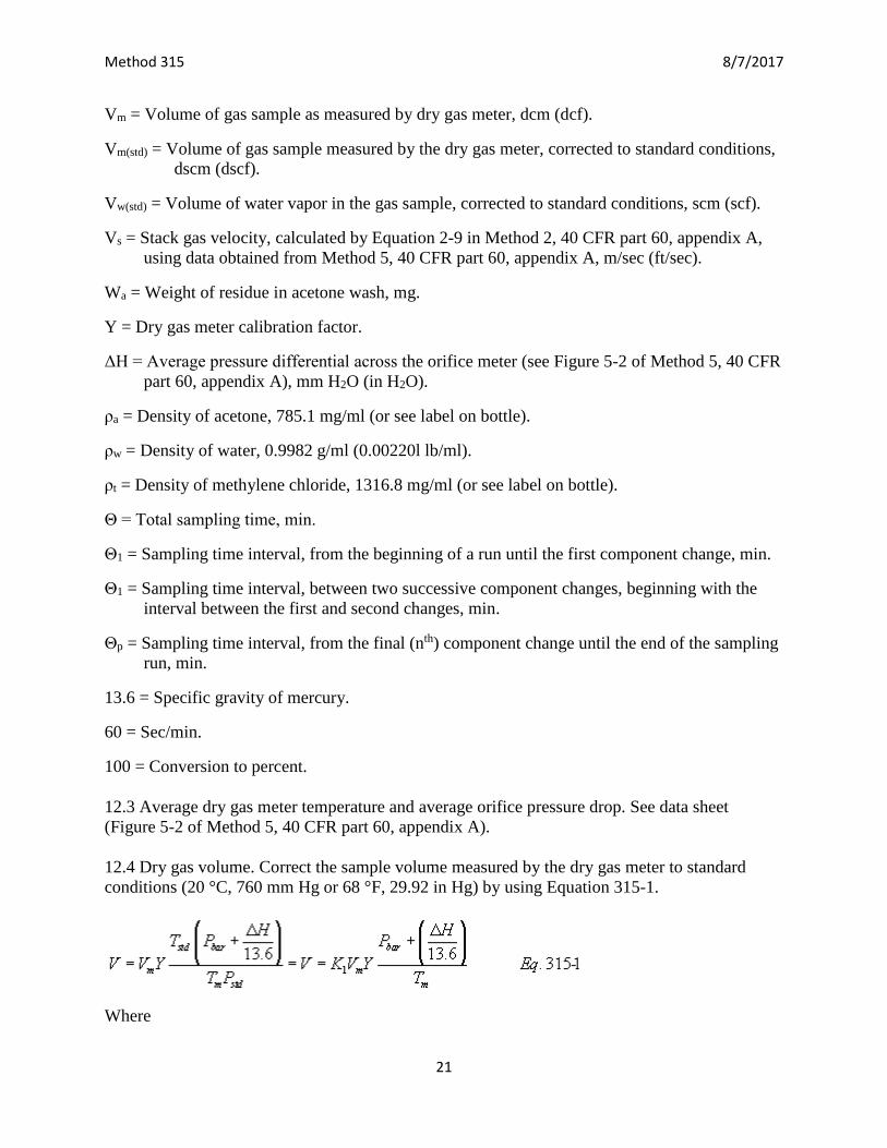
12.4 Dry gas volume. Correct the sample volume measured by the dry gas meter to standard
conditions (20 °C, 760 mm Hg or 68 °F, 29.92 in Hg) by using Equation 315-1.
Where
Page 22
Method 315 8/7/2017
22
Kl = 0.3858 °K/mm Hg for metric units,
= 17.64 °R/in Hg for English units.
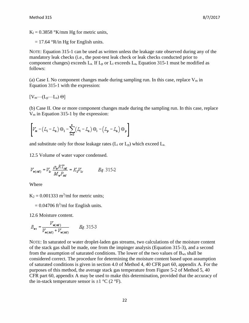
NOTE: Equation 315-1 can be used as written unless the leakage rate observed during any of the
mandatory leak checks (i.e., the post-test leak check or leak checks conducted prior to
component changes) exceeds La. If Lp or Li exceeds La, Equation 315-1 must be modified as
follows:
(a) Case I. No component changes made during sampling run. In this case, replace Vm in
Equation 315-1 with the expression:
[Vm—(Lp—La) Θ]
(b) Case II. One or more component changes made during the sampling run. In this case, replace
Vm in Equation 315-1 by the expression:
and substitute only for those leakage rates (Li or Lp) which exceed La.
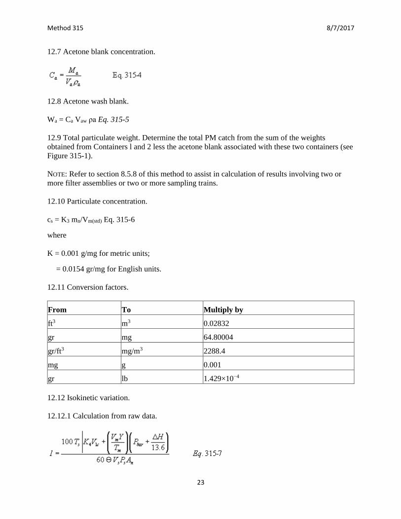
12.5 Volume of water vapor condensed.
Where
K2 = 0.001333 m3/ml for metric units;
= 0.04706 ft3/ml for English units.
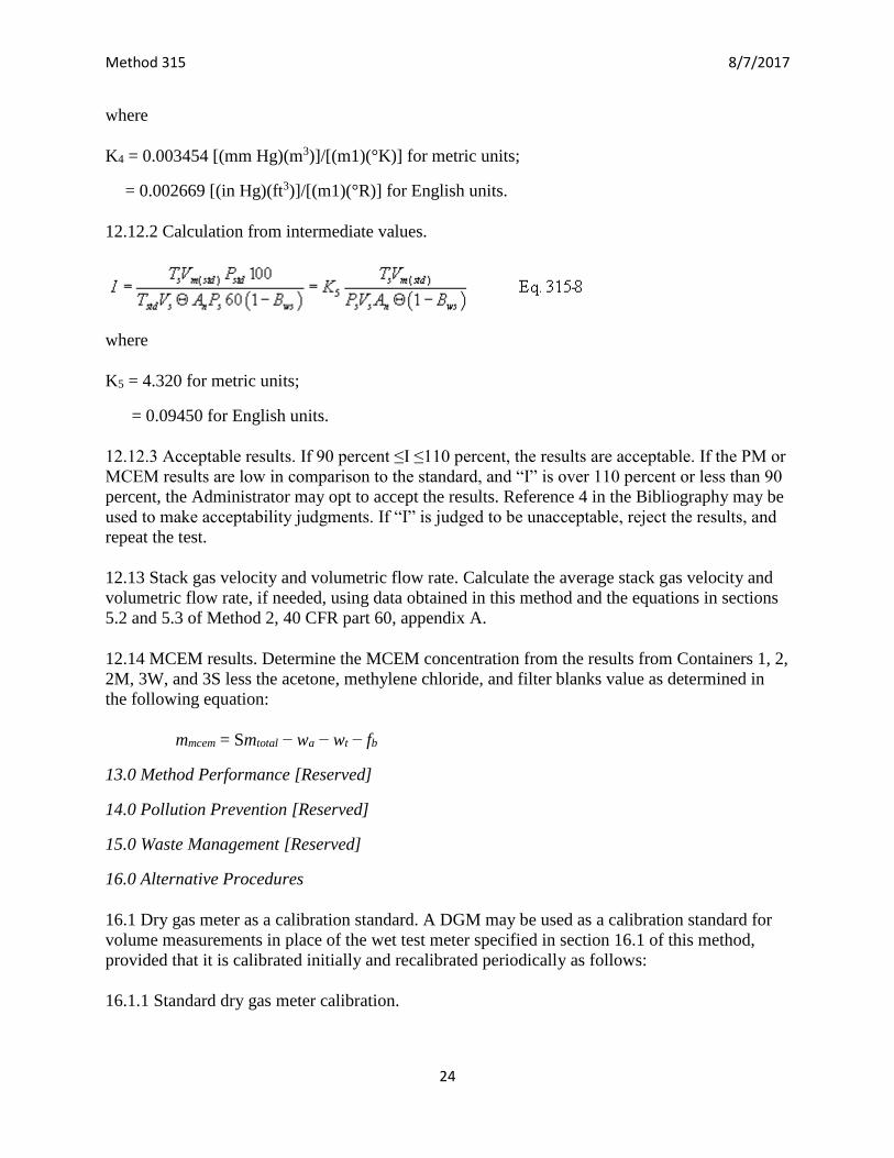
12.6 Moisture content.
NOTE: In saturated or water droplet-laden gas streams, two calculations of the moisture content
of the stack gas shall be made, one from the impinger analysis (Equation 315-3), and a second
from the assumption of saturated conditions. The lower of the two values of Bws shall be
considered correct. The procedure for determining the moisture content based upon assumption
of saturated conditions is given in section 4.0 of Method 4, 40 CFR part 60, appendix A. For the
purposes of this method, the average stack gas temperature from Figure 5-2 of Method 5, 40
CFR part 60, appendix A may be used to make this determination, provided that the accuracy of
the in-stack temperature sensor is ±1 °C (2 °F).
Page 23
Method 315 8/7/2017
23
12.7 Acetone blank concentration.
12.8 Acetone wash blank.
Wa = Ca Vaw ρa Eq. 315-5
12.9 Total particulate weight. Determine the total PM catch from the sum of the weights
obtained from Containers l and 2 less the acetone blank associated with these two containers (see
Figure 315-1).
NOTE: Refer to section 8.5.8 of this method to assist in calculation of results involving two or
more filter assemblies or two or more sampling trains.
12.10 Particulate concentration.
cs = K3 mn/Vm(std) Eq. 315-6
where
K = 0.001 g/mg for metric units;
= 0.0154 gr/mg for English units.
12.11 Conversion factors.
From To Multiply by
ft3 m3 0.02832
gr mg 64.80004
gr/ft3 mg/m3 2288.4
mg g 0.001
gr lb 1.429×10⁻⁴
12.12 Isokinetic variation.
12.12.1 Calculation from raw data.
Page 24
Method 315 8/7/2017
24
where
K4 = 0.003454 [(mm Hg)(m3)]/[(m1)(°K)] for metric units;
= 0.002669 [(in Hg)(ft3)]/[(m1)(°R)] for English units.
12.12.2 Calculation from intermediate values.
where
K5 = 4.320 for metric units;
= 0.09450 for English units.
12.12.3 Acceptable results. If 90 percent ≤I ≤110 percent, the results are acceptable. If the PM or
MCEM results are low in comparison to the standard, and “I” is over 110 percent or less than 90
percent, the Administrator may opt to accept the results. Reference 4 in the Bibliography may be
used to make acceptability judgments. If “I” is judged to be unacceptable, reject the results, and
repeat the test.
12.13 Stack gas velocity and volumetric flow rate. Calculate the average stack gas velocity and
volumetric flow rate, if needed, using data obtained in this method and the equations in sections
5.2 and 5.3 of Method 2, 40 CFR part 60, appendix A.
12.14 MCEM results. Determine the MCEM concentration from the results from Containers 1, 2,
2M, 3W, and 3S less the acetone, methylene chloride, and filter blanks value as determined in
the following equation:
mmcem = Smtotal − wa − wt − fb
13.0 Method Performance [Reserved]
14.0 Pollution Prevention [Reserved]
15.0 Waste Management [Reserved]
16.0 Alternative Procedures
16.1 Dry gas meter as a calibration standard. A DGM may be used as a calibration standard for
volume measurements in place of the wet test meter specified in section 16.1 of this method,
provided that it is calibrated initially and recalibrated periodically as follows:
16.1.1 Standard dry gas meter calibration.
Page 25
Method 315 8/7/2017
25
16.1.1.1. The DGM to be calibrated and used as a secondary reference meter should be of high
quality and have an appropriately sized capacity, e.g., 3 liters/rev (0.1 ft3/rev). A spirometer (400
liters or more capacity), or equivalent, may be used for this calibration, although a wet test meter
is usually more practical. The wet test meter should have a capacity of 30 liters/rev (1 ft3/rev)
and be capable of measuring volume to within 1.0 percent; wet test meters should be checked
against a spirometer or a liquid displacement meter to ensure the accuracy of the wet test meter.
Spirometers or wet test meters of other sizes may be used, provided that the specified accuracies
of the procedure are maintained.
16.1.1.2 Set up the components as shown in Figure 5-7 of Method 5, 40 CFR part 60, appendix
A. A spirometer, or equivalent, may be used in place of the wet test meter in the system. Run the
pump for at least 5 minutes at a flow rate of about 10 liters/min (0.35 cfm) to condition the
interior surface of the wet test meter. The pressure drop indicated by the manometer at the inlet
side of the DGM should be minimized (no greater than 100 mm H2O [4 in. H2O] at a flow rate of
30 liters/min [1 cfm]). This can be accomplished by using large-diameter tubing connections and
straight pipe fittings.
16.1.1.3 Collect the data as shown in the example data sheet (see Figure 5-8 of Method 5, 40
CFR part 60, appendix A). Make triplicate runs at each of the flow rates and at no less than five
different flow rates. The range of flow rates should be between 10 and 34 liters/min (0.35 and 1.2
cfm) or over the expected operating range.
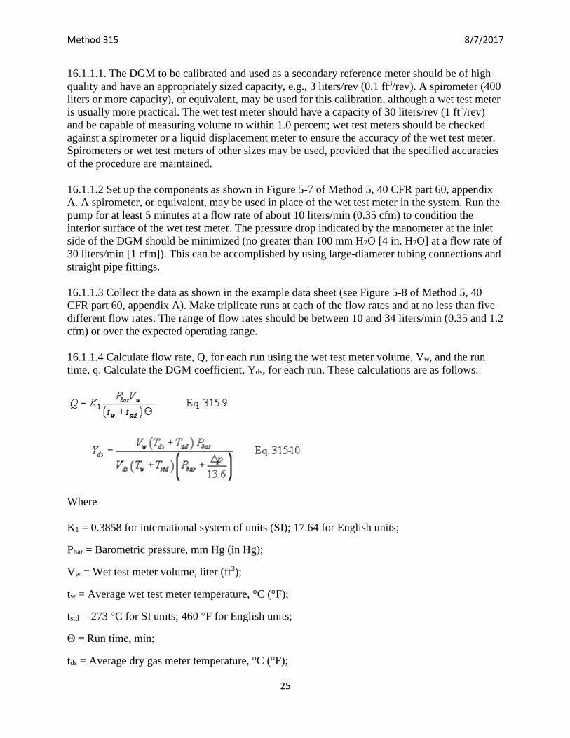
16.1.1.4 Calculate flow rate, Q, for each run using the wet test meter volume, Vw, and the run
time, q. Calculate the DGM coefficient, Yds, for each run. These calculations are as follows:
Where
K1 = 0.3858 for international system of units (SI); 17.64 for English units;
Pbar = Barometric pressure, mm Hg (in Hg);
Vw = Wet test meter volume, liter (ft3);
tw = Average wet test meter temperature, °C (°F);
tstd = 273 °C for SI units; 460 °F for English units;
Θ = Run time, min;
tds = Average dry gas meter temperature, °C (°F);
Page 26
Method 315 8/7/2017
26
Vds = Dry gas meter volume, liter (ft3);
Δp = Dry gas meter inlet differential pressure, mm H2O (in H2O).
16.1.1.5 Compare the three Yds values at each of the flow rates and determine the maximum and
minimum values. The difference between the maximum and minimum values at each flow rate
should be no greater than 0.030. Extra sets of triplicate runs may be made in order to complete
this requirement. In addition, the meter coefficients should be between 0.95 and 1.05. If these
specifications cannot be met in three sets of successive triplicate runs, the meter is not suitable as
a calibration standard and should not be used as such. If these specifications are met, average the
three Yds values at each flow rate resulting in five average meter coefficients, Yds.
16.1.1.6 Prepare a curve of meter coefficient, Yds, versus flow rate, Q, for the DGM. This curve
shall be used as a reference when the meter is used to calibrate other DGMs and to determine
whether recalibration is required.
16.1.2 Standard dry gas meter recalibration.
16.1.2.1 Recalibrate the standard DGM against a wet test meter or spirometer annually or after
every 200 hours of operation, whichever comes first. This requirement is valid provided the
standard DGM is kept in a laboratory and, if transported, cared for as any other laboratory
instrument. Abuse to the standard meter may cause a change in the calibration and will require
more frequent recalibrations.
16.1.2.2 As an alternative to full recalibration, a two-point calibration check may be made.
Follow the same procedure and equipment arrangement as for a full recalibration, but run the
meter at only two flow rates (suggested rates are 14 and 28 liters/min [0.5 and 1.0 cfm]).
Calculate the meter coefficients for these two points, and compare the values with the meter
calibration curve. If the two coefficients are within 1.5 percent of the calibration curve values at
the same flow rates, the meter need not be recalibrated until the next date for a recalibration
check.
6.2 Critical orifices as calibration standards. Critical orifices may be used as calibration
standards in place of the wet test meter specified in section 10.3 of this method, provided that
they are selected, calibrated, and used as follows:
16.2.1 Selection of critical orifices.
16.2.1.1 The procedure that follows describes the use of hypodermic needles or stainless steel
needle tubing that has been found suitable for use as critical orifices. Other materials and critical
orifice designs may be used provided the orifices act as true critical orifices; i.e., a critical
vacuum can be obtained, as described in section 7.2.2.2.3 of Method 5, 40 CFR part 60,
appendix A. Select five critical orifices that are appropriately sized to cover the range of flow
rates between 10 and 34 liters/min or the expected operating range. Two of the critical orifices
should bracket the expected operating range. A minimum of three critical orifices will be needed
to calibrate a Method 5 DGM; the other two critical orifices can serve as spares and provide
Page 27
Method 315 8/7/2017
27
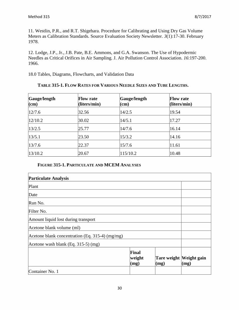
better selection for bracketing the range of operating flow rates. The needle sizes and tubing
lengths shown in Table 315-1 give the approximate flow rates indicated in the table.
16.2.1.2 These needles can be adapted to a Method 5 type sampling train as follows: Insert a
serum bottle stopper, 13×20 mm sleeve type, into a 0.5 in Swagelok quick connect. Insert the
needle into the stopper as shown in Figure 5-9 of Method 5, 40 CFR part 60, appendix A.
16.2.2 Critical orifice calibration. The procedure described in this section uses the Method 5
meter box configuration with a DGM as described in section 6.1.1.9 of this method to calibrate
the critical orifices. Other schemes may be used, subject to the approval of the Administrator.
16.2.2.1 Calibration of meter box. The critical orifices must be calibrated in the same
configuration as they will be used; i.e., there should be no connections to the inlet of the orifice.
16.2.2.1.1 Before calibrating the meter box, leak-check the system as follows: Fully open the
coarse adjust valve and completely close the bypass valve. Plug the inlet. Then turn on the pump
and determine whether there is any leakage. The leakage rate shall be zero; i.e., no detectable
movement of the DGM dial shall be seen for 1 minute.
16.2.2.1.2 Check also for leakages in that portion of the sampling train between the pump and the
orifice meter. See section 5.6 of Method 5, 40 CFR part 60, appendix A for the procedure; make
any corrections, if necessary. If leakage is detected, check for cracked gaskets, loose fittings,
worn 0-rings, etc. and make the necessary repairs.
16.2.2.1.3 After determining that the meter box is leakless, calibrate the meter box according to
the procedure given in section 5.3 of Method 5, 40 CFR part 60, appendix A. Make sure that the
wet test meter meets the requirements stated in section 7.1.1.1 of Method 5, 40 CFR part 60,
appendix A. Check the water level in the wet test meter. Record the DGM calibration factor, Y.
16.2.2.2 Calibration of critical orifices. Set up the apparatus as shown in Figure 5-10 of Method
5, 40 CFR part 60, appendix A.
16.2.2.2.1 Allow a warm-up time of 15 minutes. This step is important to equilibrate the
temperature conditions through the DGM.
16.2.2.2.2 Leak-check the system as in section 7.2.2.1.1 of Method 5, 40 CFR part 60, appendix
A. The leakage rate shall be zero.
16.2.2.2.3 Before calibrating the critical orifice, determine its suitability and the appropriate
operating vacuum as follows: turn on the pump, fully open the coarse adjust valve, and adjust the
bypass valve to give a vacuum reading corresponding to about half of atmospheric pressure.
Observe the meter box orifice manometer reading, DH. Slowly increase the vacuum reading until
a stable reading is obtained on the meter box orifice manometer. Record the critical vacuum for
each orifice. Orifices that do not reach a critical value shall not be used.
Page 28
Method 315 8/7/2017
28
16.2.2.2.4 Obtain the barometric pressure using a barometer as described in section 6.1.2 of this
method. Record the barometric pressure, Pbar, in mm Hg (in. Hg).
16.2.2.2.5 Conduct duplicate runs at a vacuum of 25 to 50 mm Hg (1 to 2 in. Hg) above the
critical vacuum. The runs shall be at least 5 minutes each. The DGM volume readings shall be in
increments of complete revolutions of the DGM. As a guideline, the times should not differ by
more than 3.0 seconds (this includes allowance for changes in the DGM temperatures) to achieve
±0.5 percent in K′. Record the information listed in Figure 5-11 of Method 5, 40 CFR part 60,
appendix A.
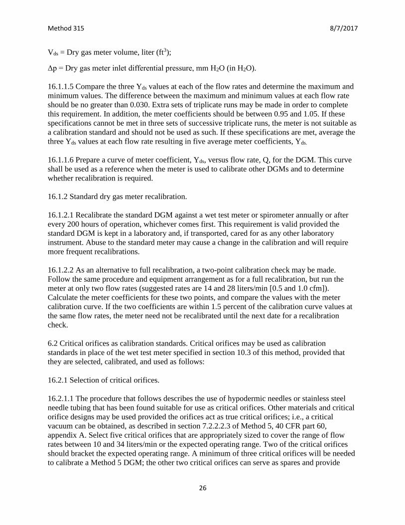
16.2.2.2.6 Calculate K′ using Equation 315-11.
where
K′ = Critical orifice coefficient, [m3)(°K)1/2]/[(mm Hg)(min)] [(ft3)(°R)1/2)]/[(in. Hg)(min)]
Tamb = Absolute ambient temperature, °K (°R).
16.2.2.2.7 Average the K′ values. The individual K′ values should not differ by more than ±0.5
percent from the average.
16.2.3 Using the critical orifices as calibration standards.
16.2.3.1 Record the barometric pressure.
16.2.3.2 Calibrate the metering system according to the procedure outlined in sections 7.2.2.2.1
to 7.2.2.2.5 of Method 5, 40 CFR part 60, appendix A. Record the information listed in Figure 5-
12 of Method 5, 40 CFR part 60, appendix A.
16.2.3.3 Calculate the standard volumes of air passed through the DGM and the critical orifices,
and calculate the DGM calibration factor, Y, using the equations below:
Vm(std) = K1 Vm [Pbar + (ΔH/13.6)]/Tm Eq. 315-12
Vcr(std) = K′ (Pbar Θ)/Tamb1/2 Eq. 315-13
Y = Vcr(std)/Vm(std) Eq. 315-14
where
Vcr(std) = Volume of gas sample passed through the critical orifice, corrected to standard
conditions, dscm (dscf).
Page 29
Method 315 8/7/2017
29
K′ = 0.3858 °K/mm Hg for metric units
= 17.64 °R/in Hg for English units.
16.2.3.4 Average the DGM calibration values for each of the flow rates. The calibration factor,
Y, at each of the flow rates should not differ by more than ±2 percent from the average.
16.2.3.5 To determine the need for recalibrating the critical orifices, compare the DGM Y factors
obtained from two adjacent orifices each time a DGM is calibrated; for example, when checking
orifice 13/2.5, use orifices 12/10.2 and 13/5.1. If any critical orifice yields a DGM Y factor
differing by more than 2 percent from the others, recalibrate the critical orifice according to
section 7.2.2.2 of Method 5, 40 CFR part 60, appendix A.
17.0 References
1. Addendum to Specifications for Incinerator Testing at Federal Facilities. PHS, NCAPC.
December 6, 1967.
2. Martin, Robert M. Construction Details of Isokinetic Source-Sampling Equipment.
Environmental Protection Agency. Research Triangle Park, NC. APTD-0581. April 1971.
3. Rom, Jerome J. Maintenance, Calibration, and Operation of Isokinetic Source Sampling
Equipment. Environmental Protection Agency. Research Triangle Park, NC. APTD-0576. March
1972.
4. Smith, W.S., R.T. Shigehara, and W.F. Todd. A Method of Interpreting Stack Sampling Data.
Paper Presented at the 63rd Annual Meeting of the Air Pollution Control Association, St. Louis,
MO. June 14-19, 1970.
5. Smith, W.S., et al. Stack Gas Sampling Improved and Simplified With New Equipment.
APCA Paper No. 67-119. 1967.
6. Specifications for Incinerator Testing at Federal Facilities. PHS, NCAPC. 1967.
7. Shigehara, R.T. Adjustment in the EPA Nomograph for Different Pitot Tube Coefficients and
Dry Molecular Weights. Stack Sampling News 2:4-11. October 1974.
8. Vollaro, R.F. A Survey of Commercially Available Instrumentation for the Measurement of
Low-Range Gas Velocities. U.S. Environmental Protection Agency, Emission Measurement
Branch. Research Triangle Park, NC. November 1976 (unpublished paper).
9. Annual Book of ASTM Standards. Part 26. Gaseous Fuels; Coal and Coke; Atmospheric
Analysis. American Society for Testing and Materials. Philadelphia, PA. 1974. pp. 617-622.
10. Felix, L.G., G.I. Clinard, G.E. Lacy, and J.D. McCain. Inertial Cascade Impactor Substrate
Media for Flue Gas Sampling. U.S. Environmental Protection Agency. Research Triangle Park,
NC 27711. Publication No. EPA-600/7-77-060. June 1977. 83 p.
Page 30
Method 315 8/7/2017
30
11. Westlin, P.R., and R.T. Shigehara. Procedure for Calibrating and Using Dry Gas Volume
Meters as Calibration Standards. Source Evaluation Society Newsletter. 3(1):17-30. February
1978.
12. Lodge, J.P., Jr., J.B. Pate, B.E. Ammons, and G.A. Swanson. The Use of Hypodermic
Needles as Critical Orifices in Air Sampling. J. Air Pollution Control Association. 16:197-200.
1966.
18.0 Tables, Diagrams, Flowcharts, and Validation Data
TABLE 315-1. FLOW RATES FOR VARIOUS NEEDLE SIZES AND TUBE LENGTHS.
Gauge/length
(cm)
Flow rate
(liters/min)
Gauge/length
(cm)
Flow rate
(liters/min)
12/7.6 32.56 14/2.5 19.54
12/10.2 30.02 14/5.1 17.27
13/2.5 25.77 14/7.6 16.14
13/5.1 23.50 15/3.2 14.16
13/7.6 22.37 15/7.6 11.61
13/10.2 20.67 115/10.2 10.48
FIGURE 315-1. PARTICULATE AND MCEM ANALYSES
Particulate Analysis
Plant
Date
Run No.
Filter No.
Amount liquid lost during transport
Acetone blank volume (ml)
Acetone blank concentration (Eq. 315-4) (mg/mg)
Acetone wash blank (Eq. 315-5) (mg)
Final
weight
(mg)
Tare weight
(mg)
Weight gain
(mg)
Container No. 1
Page 31
Method 315 8/7/2017
31
Container No. 2
Total
Less Acetone blank
Weight of particulate matter
Final
volume (mg)
Initial
volume (mg)
Liquid
collected (mg)
Moisture Analysis
Impingers Note 1 Note 1
Silica gel
Total
Note 1: Convert volume of water to weight by
multiplying by the density of water (1 g/ml).
Container No.
Final
weight
(mg)
Tare of
aluminum dish
(mg)
Weight
gain
Acetone wash
volume (ml)
Methylene chloride
wash volume (ml)
MCEM Analysis
1
2+2M
3W
3S
Total Σmtotal 0Vaw ΣVtw
Less acetone wash blank (mg) (not to exceed 1 mg/l of
acetone used)
wa = capa ΣVaw
Less methylene chloride wash blank (mg) (not to exceed
1.5 mg/l of methylene chloride used)
wt = ctpt ΣVtw
Less filter blank (mg) (not to exceed . . . (mg/filter) Fb
MCEM weight (mg) mMCEOM = Σmtotal − wa − wt−fb