CD-ROM 8015B - 1 Revision 2 December 1996 METHOD 8015B NONHALOGENATED ORGANICS USING GC/FID 1.0 SCOPE AND APPLICATION 1.1 Method 8015 is used to determine the concentration of various nonhalogenated volatile organic compounds and semivolatile organic compounds by gas chromatography. The following compounds can be determined quantitatively by this method: Appropriate Technique Compound Name Purge-and- Direct Solvent CAS No. Trap Injection Extraction a Acetone 67-64-1 pp b,d I Acetonitrile 75-05-8 pp b,d I Acrolein 107-02-8 pp b,d I Acrylonitrile 107-13-1 pp b,d I Allyl alcohol 107-18-6 ht b,d I 1-Butanol (n-Butyl alcohol) 71-36-3 ht b,d I t-Butyl alcohol 75-65-0 pp b,d I 2-Chloroacrylonitrile (I.S.) 920-37-6 NA d NA Crotonaldehyde 123-73-9 pp b,d I Diethyl ether 60-29-7 b b I 1,4-Dioxane 123-91-1 pp b,d I Ethanol 64-17-5 I b,d I Ethyl acetate 141-78-6 I b,d I Ethylene glycol 107-21-1 I b I Ethylene oxide 75-21-8 I b,d I Hexafluoro-2-propanol (I.S.) 920-66-1 NA d NA Hexafluoro-2-methyl- 2-propanol (I.S.) 515-14-6 NA d NA Isobutyl alcohol 78-83-1 pp b,d I Isopropyl alcohol 67-63-0 pp b,d I Methanol 67-56-1 I b,d I Methyl ethyl ketone (MEK) 78-93-3 pp b,d I Methyl isobutyl ketone (MIBK) 108-10-1 pp b,d I N-Nitroso-di-n-butylamine 924-16-3 pp b,d b Paraldehyde 123-63-7 pp b,d I 2-Pentanone 107-87-9 pp b,d I 2-Picoline 109-06-8 pp b,d I 1-Propanol 71-23-8 pp b,d I Propionitrile 107-12-0 ht d I
Transcript
CD-ROM 8015B - 1 Revision 2December 1996
METHOD 8015B
NONHALOGENATED ORGANICS USING GC/FID
1.0 SCOPE AND APPLICATION
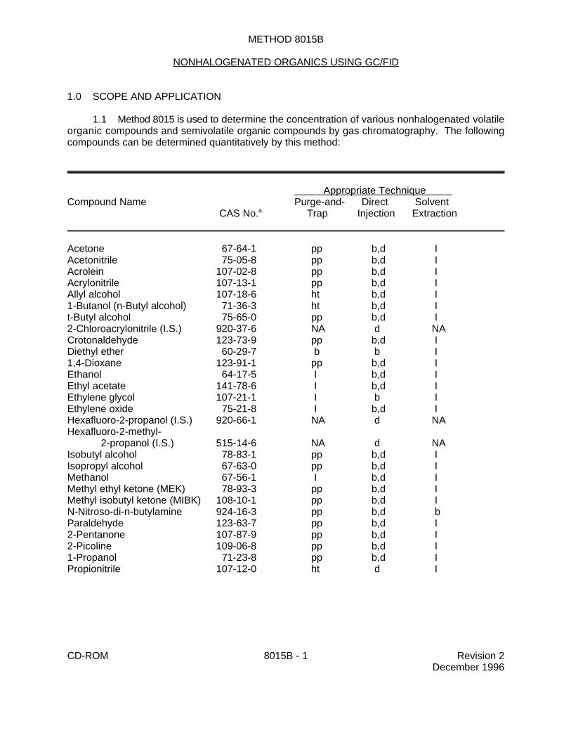
1.1 Method 8015 is used to determine the concentration of various nonhalogenated volatileorganic compounds and semivolatile organic compounds by gas chromatography. The followingcompounds can be determined quantitatively by this method:
Appropriate Technique Compound Name Purge-and- Direct Solvent CAS No. Trap Injection Extraction a
Acetone 67-64-1 pp b,d IAcetonitrile 75-05-8 pp b,d IAcrolein 107-02-8 pp b,d IAcrylonitrile 107-13-1 pp b,d IAllyl alcohol 107-18-6 ht b,d I1-Butanol (n-Butyl alcohol) 71-36-3 ht b,d It-Butyl alcohol 75-65-0 pp b,d I2-Chloroacrylonitrile (I.S.) 920-37-6 NA d NACrotonaldehyde 123-73-9 pp b,d IDiethyl ether 60-29-7 b b I1,4-Dioxane 123-91-1 pp b,d IEthanol 64-17-5 I b,d IEthyl acetate 141-78-6 I b,d IEthylene glycol 107-21-1 I b IEthylene oxide 75-21-8 I b,d IHexafluoro-2-propanol (I.S.) 920-66-1 NA d NAHexafluoro-2-methyl-
Appropriate Technique Compound Name Purge-and- Direct Solvent CAS No. Trap Injection Extraction a
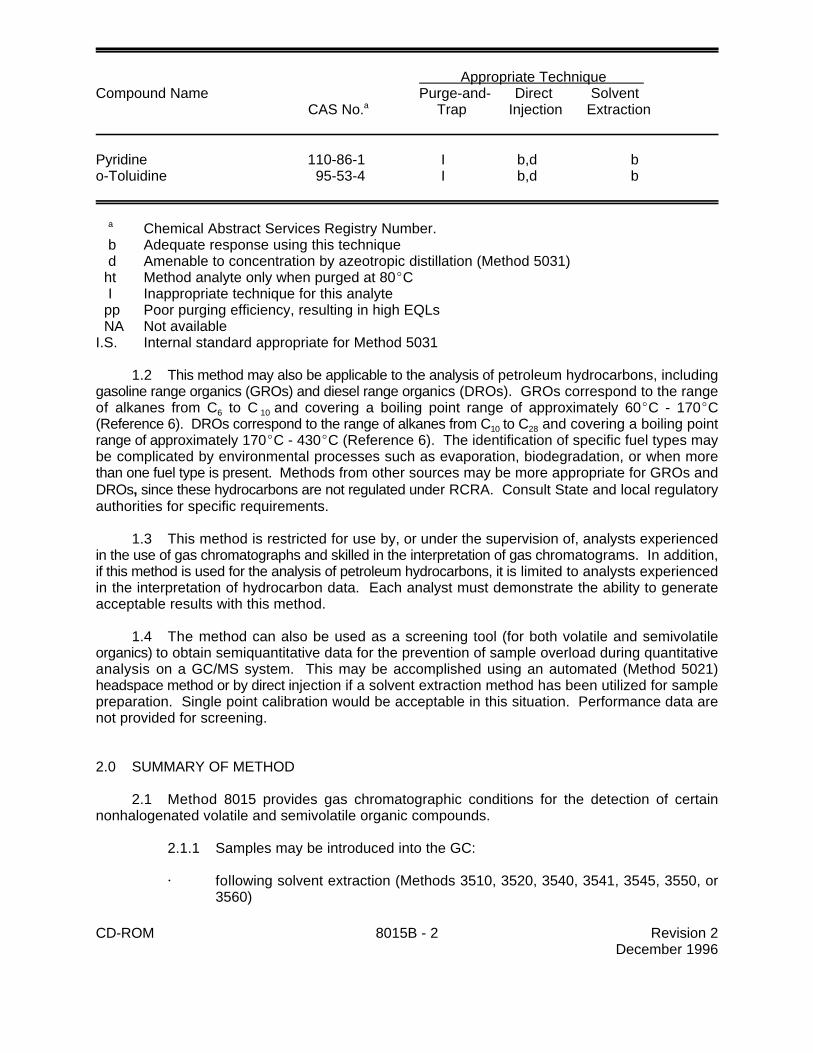
Pyridine 110-86-1 I b,d bo-Toluidine 95-53-4 I b,d b
Chemical Abstract Services Registry Number.a
b Adequate response using this technique d Amenable to concentration by azeotropic distillation (Method 5031) ht Method analyte only when purged at 80EC I Inappropriate technique for this analyte pp Poor purging efficiency, resulting in high EQLs NA Not availableI.S. Internal standard appropriate for Method 5031
1.2 This method may also be applicable to the analysis of petroleum hydrocarbons, includinggasoline range organics (GROs) and diesel range organics (DROs). GROs correspond to the rangeof alkanes from C to C and covering a boiling point range of approximately 60EC - 170EC6 10
(Reference 6). DROs correspond to the range of alkanes from C to C and covering a boiling point10 28
range of approximately 170EC - 430EC (Reference 6). The identification of specific fuel types maybe complicated by environmental processes such as evaporation, biodegradation, or when morethan one fuel type is present. Methods from other sources may be more appropriate for GROs andDROs, since these hydrocarbons are not regulated under RCRA. Consult State and local regulatoryauthorities for specific requirements.
1.3 This method is restricted for use by, or under the supervision of, analysts experiencedin the use of gas chromatographs and skilled in the interpretation of gas chromatograms. In addition,if this method is used for the analysis of petroleum hydrocarbons, it is limited to analysts experiencedin the interpretation of hydrocarbon data. Each analyst must demonstrate the ability to generateacceptable results with this method.
1.4 The method can also be used as a screening tool (for both volatile and semivolatileorganics) to obtain semiquantitative data for the prevention of sample overload during quantitativeanalysis on a GC/MS system. This may be accomplished using an automated (Method 5021)headspace method or by direct injection if a solvent extraction method has been utilized for samplepreparation. Single point calibration would be acceptable in this situation. Performance data arenot provided for screening.
2.0 SUMMARY OF METHOD
2.1 Method 8015 provides gas chromatographic conditions for the detection of certainnonhalogenated volatile and semivolatile organic compounds.
@ by direct injection (aqueous samples) including the concentration of analytes byazeotropic distillation (Method 5031)
@ by purge-and-trap (Methods 5030 or 5035), or
@ by vacuum distillation (Method 5032)
2.1.2 Ground or surface water samples must generally be analyzed in conjunction withMethods 5030, 5031, 5032, 3510, 3520, or other appropriate preparatory methods to obtainthe necessary quantitation limits. Method 3535 (solid-phase extraction) may also be applicableto the target analytes, but has not yet been validated by EPA in conjunction with Method 8015.
2.1.3 Diesel range organics (DROs) may be prepared by an appropriate solventextraction method.
2.1.4 Gasoline range organics (GROs) may be introduced into the GC/FID by purge-and-trap, automated headspace, vacuum distillation, or other appropriate technique.
2.2 An appropriate column and temperature program is used in the gas chromatograph toseparate the organic compounds. Detection is achieved by a flame ionization detector (FID).
2.3 The method allows the use of packed or capillary columns for the analysis andconfirmation of the non-halogenated individual analytes. Columns and conditions listed have beendemonstrated to provide separation of those target analytes. Analysts may change these conditionsas long as they demonstrate adequate performance.
2.4 Fused silica capillary columns are necessary for the analysis of petroleum hydrocarbons.
3.0 INTERFERENCES
3.1 When analyzing for volatile organics, samples can be contaminated by diffusion of volatileorganics (particularly chlorofluorocarbons and methylene chloride) through the sample containerseptum during shipment and storage. A trip blank prepared from organic-free reagent water andcarried through sampling and subsequent storage and handling must serve as a check on suchcontamination.
3.2 Contamination by carryover can occur whenever high-concentration andlow-concentration samples are analyzed in sequence. To reduce the potential for carryover, thesample syringe or purging device must be rinsed out between samples with an appropriate solvent.Whenever an unusually concentrated sample is encountered, it should be followed by injection ofa solvent blank to check for cross contamination.
3.2.1 Clean purging vessels with a detergent solution, rinse with distilled water, andthen dry in a 105EC oven between analyses. Clean syringes or autosamplers by flushing allsurfaces that contact samples using appropriate solvents.
3.2.2 All glassware must be scrupulously cleaned. Clean all glassware as soon aspossible after use by rinsing with the last solvent used. This should be followed by detergentwashing with hot water, and rinses with tap water and organic-free reagent water. Drain theglassware and dry in an oven at 130EC for several hours or rinse with methanol and drain.Store dry glassware in a clean environment.
CD-ROM 8015B - 4 Revision 2December 1996
3.3 The flame ionization detector (FID) is a non-selective detector. There is a potential formany non-target compounds present in samples to interfere with this analysis.
4.0 APPARATUS AND MATERIALS
4.1 Gas chromatograph
4.1.1 Gas Chromatograph - Analytical system complete with gas chromatographsuitable for solvent injections or purge-and-trap sample introduction and all requiredaccessories, including detectors, column supplies, recorder, gases, and syringes. A datasystem for measuring peak heights and/or peak areas is recommended.
4.1.2 Recommended GC Columns
4.1.2.1 Column 1 - 8 ft x 0.1 in. ID stainless steel or glass column packed with1% SP-1000 on Carbopack-B 60/80 mesh or equivalent.
4.1.2.2 Column 2 - 6 ft x 0.1 in. ID stainless steel or glass column packed withn-octane on Porasil-C 100/120 mesh (Durapak) or equivalent.
4.1.2.3 Column 3 - 30 m x 0.53 mm ID fused silica capillary column bonded withDB-Wax (or equivalent), 1-µm film thickness.
4.1.2.4 Column 4 - 30 m x 0.53 mm ID fused silica capillary column chemicallybonded with 5% methyl silicone (DB-5, SPB-5, RTx, or equivalent), 1.5-µm film thickness.
4.1.2.4.1 Capillary columns are needed for petroleum hydrocarbonanalyses. Laboratories may use other capillary columns (e.g. 0.25-0.32 mm IDcapillary columns) if they document method performance data (e.g.chromatographic resolution and MDLs) if appropriate for the intended use of thedata.
4.1.2.4.2 Wide-bore columns should be installed in 1/4-inchinjectors, with deactivated liners designed specifically for use with these columns.
4.1.3 Detector - Flame ionization (FID)
4.2 Sample introduction and preparation apparatus
4.2.1 Refer to the 5000 series sample preparation methods for the appropriateapparatus.
4.2.2 Samples may also be introduced into the GC via injection of solvent extracts ordirect injection of aqueous samples.
4.3 Syringes
4.3.1 A 5-mL Luer-Lok glass hypodermic and a 5-mL gas-tight syringe with shutoffvalve for volatile analytes.
CD-ROM 8015B - 5 Revision 2December 1996
4.3.2 Microsyringes - 10- and 25-µL with a 0.006 in. ID needle (Hamilton 702N orequivalent) and 100-µL.
4.4 Volumetric flasks, Class A - Appropriate sizes with ground glass stoppers.
4.5 Analytical balance - 0 - 160 g capacity, capable of measuring differences of 0.0001 g.
5.0 REAGENTS
5.1 Reagent grade chemicals shall be used whenever possible. Unless otherwise indicated,it is intended that all reagents shall conform to the specifications of the Committee on AnalyticalReagents of the American Chemical Society, where such specifications are available. Other gradesmay be used, provided it is first ascertained that the reagent is of sufficiently high purity to permit itsuse without lessening the accuracy of the determination.
5.2 Organic-free reagent water - All references to water in this method refer to organic-freereagent water, as defined in Chapter One.
5.3 Methanol, CH OH. Pesticide quality or equivalent. Store away from other solvents.3
5.4 Fuels, e.g., gasoline or diesel. Purchase from a commercial source. Low boilingcomponents in fuel evaporate quickly. If available, obtain fuel from the leaking tank on site.
5.5 Alkane standard. A standard containing a homologous series of n-alkanes forestablishing retention times (e.g., C -C for diesel). 10 32
5.6 Stock standards - Stock solutions may be prepared from pure standard materials orpurchased as certified solutions. When methanol is a target analyte or when using azeotropicdistillation for sample preparation, standards should not be prepared in methanol. Standards mustbe replaced after 6 months or sooner, if comparison with check standards indicates a problem.
5.7 Secondary dilution standards - Using stock standard solutions, prepare secondary dilutionstandards, as needed, that contain the compounds of interest, either singly or mixed together. Thesecondary dilution standards should be prepared at concentrations such that the aqueous calibrationstandards prepared in Sec. 5.8 will bracket the working range of the analytical system. Secondarydilution standards should be stored with minimal headspace for volatiles and should be checkedfrequently for signs of degradation or evaporation, especially just prior to preparing calibrationstandards from them.
5.8 Calibration standards - Calibration standards at a minimum of five different concentrationsare prepared in water (purge-and-trap or direct injection) or in methylene chloride (solvent injection)from the secondary dilution of the stock standards. One of the standards should be at or below theconcentration equivalent to the appropriate quantitation limit for the project. The remainingconcentrations should correspond to the expected range of concentrations found in real samples orshould define the working range of the GC. Each standard should contain each analyte for detectionby this method (e.g., some or all of the compounds listed in Sec. 1.1 may be included). Volatileorganic standards are prepared in organic-free reagent water. In order to prepare accurate aqueousstandard solutions, the following precautions must be observed:
5.8.1 Do not inject more than 20 µL of methanolic standards into 100 mL of water.
CD-ROM 8015B - 6 Revision 2December 1996
5.8.2 Use a 25-µL Hamilton 702N microsyringe or equivalent (variations in needlegeometry will adversely affect the ability to deliver reproducible volumes of methanolicstandards into water).
5.8.3 Rapidly inject the primary standard into the filled volumetric flask. Remove theneedle as fast as possible after injection.
5.8.4 Mix diluted standards by inverting the flask three times only.
5.8.5 Fill the sample syringe from the standard solution contained in the expanded areaof the flask (do not use any solution contained in the neck of the flask).
5.8.6 Never use pipets to dilute or transfer samples or aqueous standards when dilutingvolatile organic standards.
5.8.7 Aqueous standards used for purge-and-trap analyses (Method 5030) are notstable and should be discarded after 1 hour, unless held in sealed vials with zero headspace.If so stored, they may be held for up to 24 hours. Aqueous standards used for azeotropicdistillation (Method 5031) may be stored for up to a month in polytetrafluoroethylene (PTFE)-sealed screw-cap bottles with minimal headspace, at 4EC, and protected from light.
5.9 Internal standards (if internal standard calibration is used) - To use this approach, theanalyst must select one or more internal standards that are similar in analytical behavior to thecompounds of interest. The analyst must further demonstrate that the measurement of the internalstandard is not affected by method or matrix interferences. Because of these limitations, no internalstandard can be suggested that is applicable to all samples. The following internal standards arerecommended when preparing samples by azeotropic distillation: 2-chloroacrylonitrile,hexafluoro-2-propanol and hexafluoro-2-methyl-2-propanol.
5.10 Surrogate standards - Whenever possible, the analyst should monitor both theperformance of the analytical system and the effectiveness of the method in dealing with eachsample matrix by spiking each sample, standard, and blank with one or two surrogate compoundswhich are not affected by method interferences.
6.0 SAMPLE COLLECTION, PRESERVATION, AND HANDLING
See the introductory material to this chapter, Organic Analytes, Sec. 4.1.
7.0 PROCEDURE
7.1 Introduction/preparation methods
Various alternate methods are provided for sample introduction. All internal standards,surrogates, and matrix spikes (when applicable) must be added to samples before introduction intothe GC/FID system. Follow the introduction method on when to add standards.
CD-ROM 8015B - 7 Revision 2December 1996
7.1.1 Direct injection - This involves direct syringe injection into the GC injection port.
7.1.1.1 Volatile organics (includes gasoline range organics [GROs])
This may involve injection of an aqueous sample containing a very highconcentration of analytes; injection of aqueous concentrates from Method 5031(azeotropic distillation for nonpurgeable volatile organics); and injection of an organicsolvent waste. Direct injection of aqueous samples (non-concentrated) has very limitedapplications. It is only permitted for the determination of volatiles at the toxicitycharacteristic (TC) regulatory limits or at concentrations in excess of 10,000 µg/L. It mayalso be used in conjunction with the test for ignitability in aqueous samples (along withMethods 1010 and 1020) to determine if alcohol is present at > 24%.
7.1.1.2 Semivolatile organics (includes diesel range organics [DROs])
This may involve syringe injection of extracts of aqueous samples prepared byMethods 3510 or 3520 or extracts of soil/solids prepared by Methods 3540, 3541, 3545,3550 or 3560.
WARNING: Ultrasonic extraction (Method 3550) is not as rigorous a method asthe other extraction methods for soil/solids. This means it is verycritical that the method be followed explicitly to achieve extractionefficiency which approaches that of Soxhlet extraction. ConsultMethod 3550 for information on the critical aspects of this extractionprocedure.
7.1.2 Purge and trap - this includes purge and trap for aqueous samples (Method 5030)and purge and trap for solid samples (Method 5035). Method 5035 also provides techniquesfor extraction of solid and oily waste samples by methanol (and other water miscible solvents)with subsequent purge and trap from an aqueous matrix using Method 5030. Normally purgeand trap for aqueous samples is performed at ambient temperatures while soil/solid samplesutilize a 40EC purge to improve extraction efficiency. Occasionally, there may be a need toperform a heated purge for aqueous samples to lower detection limits; however, a 25-mLsample should provide the sensitivity needed in most situations.
7.1.3 Vacuum distillation - this is a device for the introduction of volatile organics fromaqueous, solid or tissue samples (Method 5032) into the GC/FID system.
7.1.4 Automated static headspace - this is a device for the introduction of volatileorganics from solid samples (Method 5021) into the GC/FID system.
7.2 Chromatographic conditions (recommended)
7.2.1 Column 1
Carrier gas (Helium) flow rate: 40 mL/minTemperature program:
Initial temperature: 45EC, hold for 3 minutesProgram: 45EC to 220EC at 8EC/minFinal temperature: 220EC, hold for 15 minutes.
CD-ROM 8015B - 8 Revision 2December 1996
7.2.2 Column 2
Carrier gas (Helium) flow rate: 40 mL/minTemperature program:
Initial temperature: 50EC, hold for 3 minutesProgram: 50EC to 170EC at 6EC/minFinal temperature: 170EC, hold for 4 minutes.
7.2.3 Column 3
Carrier gas (Helium) flow rate: 15 mL/minTemperature program:
Initial temperature: 45EC, hold for 4 minutesProgram: 45EC to 220EC at 12EC/minFinal temperature: 220EC, hold for 3 minutes.
7.2.4 Column 4 (DROs)
Carrier gas (Helium) flow rate: 5-7 mL/minuteMakeup gas (Helium) flow rate: 30 mL/min Injector temperature: 200ECDetector temperature: 340ECTemperature program:
Initial temperature: 45EC, hold 3 minuteProgram: 45EC to 275EC at 12EC/minFinal temperature: 275EC, hold 12 min
7.2.5 Column 4 (GROs)
Carrier gas (Helium) flow rate: 5-7 mL/minuteMakeup gas (Helium) flow rate: 30 mL/min Injector temperature: 200ECDetector temperature: 340ECTemperature program:
Initial temperature: 45EC, hold 1 minuteProgram: 45EC to 100EC at 5EC/minFinal temperature: 100EC to 275EC, at 8EC/minFinal hold: 5 min
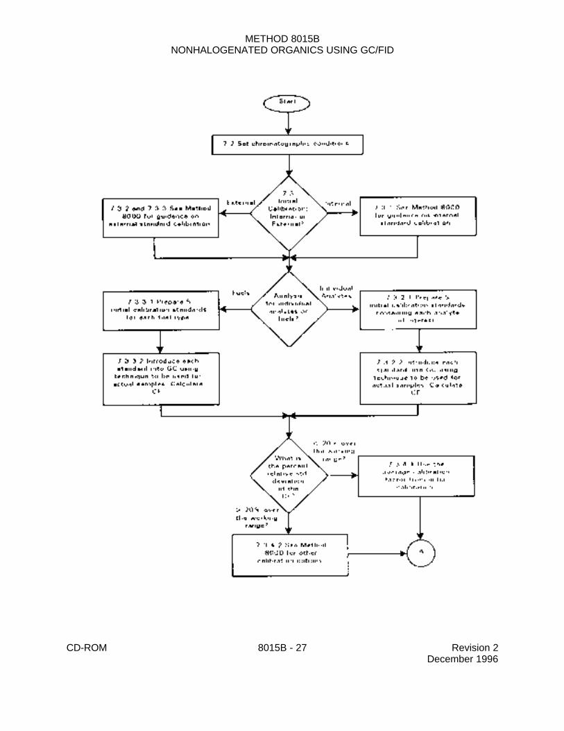
7.3 Initial calibration
7.3.1 Set up the sample introduction system as outlined in the method of choice (seeSec. 7.1). A different calibration curve is necessary for each sample introduction modebecause of the differences in conditions and equipment. Establish chromatographic operatingparameters that provide instrument performance equivalent to that documented in this method.Prepare calibration standards using the procedures described above (Sec. 5.8). The externalstandard technique is described below. Analysts wishing to use the internal standardtechnique are referred to Method 8000. Recommended internal standards for thenon-purgeable volatiles include hexafluoro-2-propanol, hexafluoro-2-methyl-2-propanol, and2-chloroacrylonitrile.
CD-ROM 8015B - 9 Revision 2December 1996
7.3.2 External standard calibration procedure for single component analytes
7.3.2.1 For each analyte and surrogate of interest, prepare calibration standardsat a minimum of five different concentrations by adding volumes of one or more stockstandards to a volumetric flask and diluting to volume with an appropriate solvent. Oneof the external standards should be at a concentration at or below the quantitation limitnecessary for the project (based on the concentration in the final volume specified in thepreparation method, with no dilutions). The other concentrations should correspond tothe expected range of concentrations found in real samples or should define the workingrange of the detector.
7.3.2.2 Introduce each calibration standard using the technique that will be usedto introduce the actual samples into the gas chromatograph. Tabulate peak height orarea responses against the mass injected. Calculate the calibration factor (CF) for eachsingle component analyte as described in Method 8000.
7.3.3 External standard calibration procedure for DROs and GROs
The calibration of DROs and GROs is markedly different from that for single componentanalytes. In particular, the response used for calibration must represent the entire area of thechromatogram within the retention time range for the fuel type (DROs or GROs), including theunresolved complex mixture that lies below the individual peaks. See Sec. 7.7.2 forinformation on calculating this area.
7.3.3.1 For each fuel type, prepare calibration standards at a minimum of fivedifferent concentrations by adding volumes of one or more stock standards to avolumetric flask and diluting to volume with an appropriate solvent. One of the externalstandards should be at a concentration at or below the quantitation limit necessary forthe project (based on the concentration in the final volume specified in the preparationmethod, with no dilutions). The other concentrations should correspond to the expectedrange of concentrations found in real samples or should define the working range of thedetector.
NOTE: Whenever possible, the calibration should be performed using thespecific fuel that is contaminating the site (e.g., a sample of the fuelremaining in the tank suspected of leaking). Where such samples arenot available or not known, use recently purchased commercially-available fuel. A qualitative screening injection and GC run may beperformed to identify unknown fuels.
7.3.3.2 Introduce each calibration standard using the technique that will be usedto introduce the actual samples into the gas chromatograph. Determine the area of theresponse as described in Sec. 7.7.2. Calculate the calibration factor (CF) for each fueltype as shown below:
Calibration Factor = Total Area within Retention Time Range
Mass injected (in nanograms)
7.3.4 Calibration linearity
The linearity of the calibration must be assessed. This applies to both the singlecomponent analytes and the fuel types.
CD-ROM 8015B - 10 Revision 2December 1996
7.3.4.1 If the percent relative standard deviation (%RSD) of the calibrationfactor is less than 20% over the working range, linearity through the origin can beassumed, and the average calibration factor can be used in place of a calibration curve.
7.3.4.2 If the % RSD is more than 20% over the working range, linearity throughthe origin cannot be assumed. See Method 8000 for other calibration options that maybe employed.
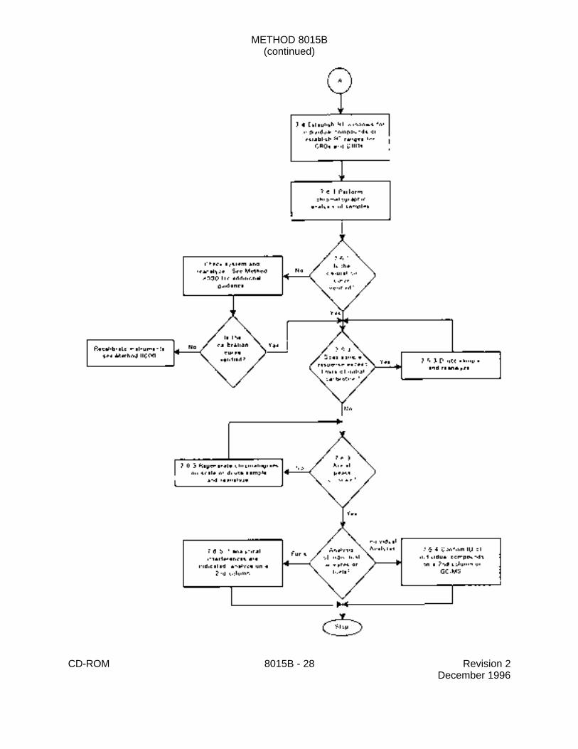
7.4 Retention time windows
Single component target analytes (see Sec. 1.1) are identified on the basis of retentiontime windows. GROs and DROs are distinguished on the basis of the ranges of retentiontimes for characteristic components in each type of fuel.
7.4.1 Before establishing retention time windows, make sure that the chromatographicsystem is functioning reliably and that the operating parameters have been optimized for thetarget analytes and surrogates in the sample matrix to be analyzed. Establish the retentiontime windows for single component target analytes using the procedure described in Sec. 7.0of Method 8000.
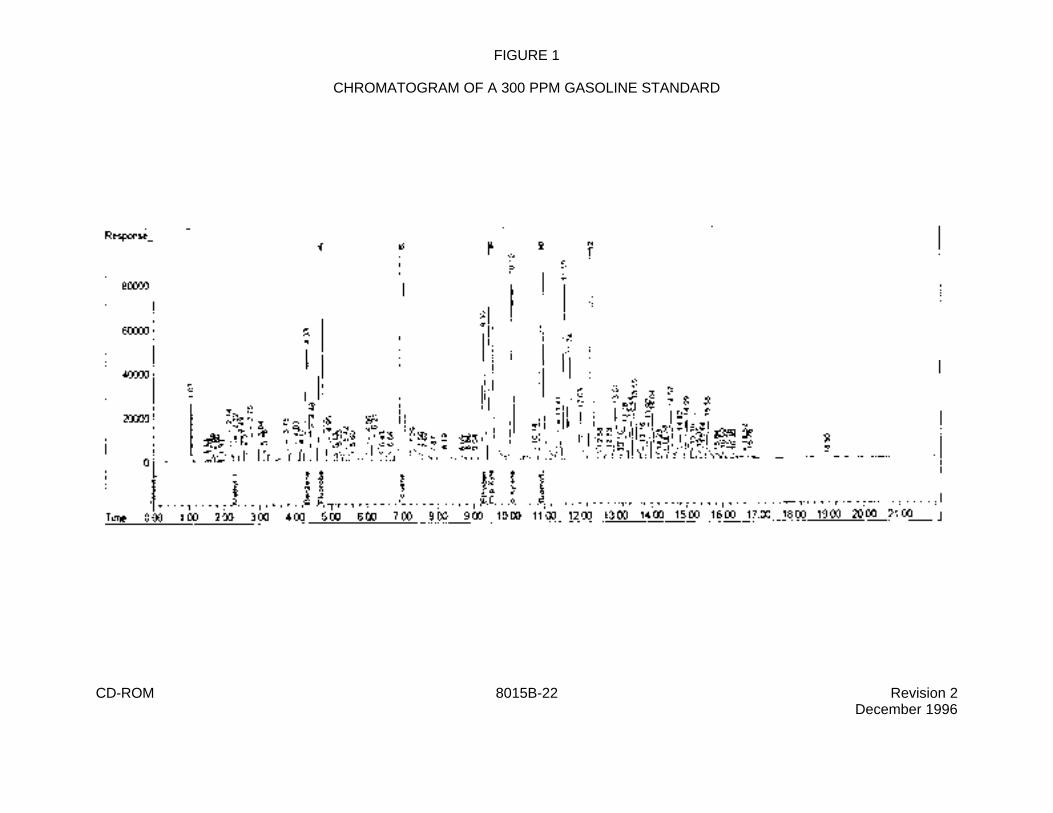
7.4.2 The retention time range for GROs is defined during initial calibration. Twospecific gasoline components are used to establish the range, 2-methylpentane and 1,2,4-trimethylbenzene. Use the procedure described in Sec. 7.0 of Method 8000 to establish theretention time windows for these two components. The retention time range is then calculatedbased on the lower limit of the RT window for the first eluting component and the upper limitof the RT window for the last eluting component.
7.4.3 The retention time range for DROs is defined during initial calibration. The rangeis established from the retention times of the C and C alkanes. Use the procedure10 28
described in Sec. 7.0 of Method 8000 to establish the retention time windows for these twocomponents. The retention time range is then calculated based on the lower limit of the RTwindow for the first eluting component and the upper limit of the RT window for the last elutingcomponent.
7.5 Calibration verification
7.5.1 The working calibration curve, and retention times must be verified at thebeginning of each 12-hour work shift as a minimum requirement. Verification is accomplishedby the measurement of one or more calibration standards (normally mid-concentration) thatcontain all of the target analytes and surrogates when individual target analytes are beinganalyzed. Verification is accomplished by the measurement of the fuel standard and thehydrocarbon retention time standard when petroleum hydrocarbons are being analyzed.Additional analyses of the verification standard(s) throughout a 12-hour shift are stronglyrecommended, especially for samples that contain visible concentrations of oily material. SeeSec. 7.0 "calibration verification" of Method 8000 for more detailed information.
7.5.2 Calculate the % difference as detailed in Sec. 7.0 of Method 8000. If theresponse for any analyte is within ±15% of the response obtained during the initial calibration,then the initial calibration is considered still valid, and analyst may continue to use the meanCF or RF values from the initial calibration to quantitate sample results. For analysesemploying azeotropic distillation as the sample introduction technique, the % difference maybe up to ±20%. If the response for any analyte varies from the predicted response by more
CD-ROM 8015B - 11 Revision 2December 1996
than ±15% (±20% for azeotropic distillation), corrective action must be taken to restore thesystem or a new calibration curve must be prepared for that compound.
7.5.3 All target analytes and surrogates or n-alkanes in the calibration verificationanalyses must fall within previously established retention time windows. If the retention timeof any analyte does not fall within the ± 3F window, corrective action must be taken to restorethe system or a new calibration curve must be prepared for that compound.
7.5.4 Solvent blanks and any method blanks should be run with calibration verificationanalyses to confirm that laboratory contamination does not cause false positives.
7.6 Gas chromatographic analysis
7.6.1 Samples are analyzed in a set referred to as an analysis sequence. Thesequence begins with calibration verification followed by sample extract analyses. Additionalanalyses of the verification standard(s) throughout a 12-hour shift are strongly recommended,especially for samples that contain visible concentrations of oily material. A verificationstandard is also necessary at the end of a set. The sequence ends when the set of sampleshas been injected or when retention time and/or % difference QC criteria are exceeded.
If the criteria are exceeded, inspect the gas chromatographic system to determine thecause and perform whatever maintenance is necessary before recalibrating and proceedingwith sample analysis. All sample analyses performed using external standard calibration mustbe bracketed with acceptable data quality analyses (e.g., calibration and retention time criteria).Therefore, all samples must be reanalyzed that fall within the standard that exceeded criteriaand the last standard that was acceptable.
7.6.2 Samples are analyzed with the same instrument configuration as is used duringcalibration. When using Method 5030 for sample introduction, analysts are cautioned thatopening a sample vial or drawing an aliquot from a sealed vial (thus creating headspace) willcompromise samples analyzed for volatiles. Therefore, it is recommended that analystsprepare two samples for purge-and-trap analysis. The second sample can be stored for 24hours to ensure that an uncompromised sample is available for analysis or dilution, if theanalysis of the first sample is unsuccessful or if results exceed the calibration range of theinstrument. Distillates from Method 5031 may be split into two portions and held at 4EC priorto analysis. It is recommended that the distillate be analyzed within 24 hours of distillation.Distillates must be analyzed within 7 days of distillation.
7.6.3 Sample concentrations are calculated by comparing sample response data withthe initial calibration of the system (Sec. 7.3). Therefore, if sample response exceeds the limitsof the initial calibration range, a dilution of the sample must be analyzed. For volatile organicaqueous samples, the dilution must be performed on a second aliquot of the sample which hasbeen properly sealed and stored prior to use and reanalysis. Extracts should be diluted so thatall peaks are on scale, as overlapping peaks are not always evident when peaks are off scale.Computer reproduction of chromatograms, manipulated to ensure all peaks are on scale overa 100-fold range, are acceptable as long as calibration limits are not exceeded. Peak heightmeasurements are recommended over peak area integration when overlapping peaks causeerrors in area integration.
7.6.4 Tentative identification of a single component analyte occurs when a peak froma sample extract falls within the daily retention time window. Confirmation is required on asecond column or by GC/MS. Since the flame ionization detector is non-specific, it is highly
CD-ROM 8015B - 12 Revision 2December 1996
recommended that GC/MS confirmation be performed on single component analytes unlesshistorical data are available to support the identification(s).
7.6.5 Second column confirmation is generally not necessary for petroleumhydrocarbon analysis. However, if analytical interferences are indicated, analysis using thesecond GC column is required. Also, the analyst must ensure that the sample hydrocarbonsfall within the retention time range established during the initial calibration.
NOTE: Identification of fuels, especially gasoline, is complicated by their inherentvolatility. The early eluting compounds in fuels are obviously the most volatileand the most likely to have weathered unless sampled immediately followinga spill. The most highly volatile fraction of gasoline constitutes 50% of thetotal peak area of a gasoline chromatogram. This fraction is least likely to bepresent in an environmental sample or present in only very low concentrationin relation to the remainder of a gasoline chromatogram.
7.6.6 The performance of the entire analytical system should be checked every 12hours, using data gathered from analyses of blanks, standards, and replicate samples.Significant peak tailing must be corrected. Tailing problems are generally traceable to activesites on the column, cold spots in a GC, the detector operation, or leaks in the system. SeeSec. 7.9 for GC/FID system maintenance. Follow manufacturer's instructions for maintenanceof the introduction device.
7.7 Calculations
7.7.1 The concentration of each analyte in the sample may be determined bycalculating the amount of standard purged or injected, from the peak response, using thecalibration curve or the mean CF or RF from the initial curve.
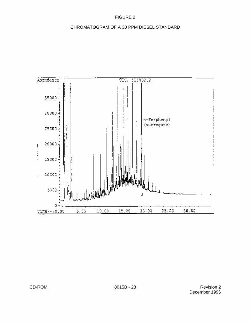
7.7.2 While both diesel fuel and gasoline contain a large number of compounds thatwill produce well resolved peaks in a GC/FID chromatogram, both fuels contain many othercomponents that are not chromatographically resolved. This unresolved complex mixtureresults in the "hump" in the chromatogram that is characteristic of these fuels. In addition,although the resolved peaks are important for the identification of the specific fuel type, thearea of the unresolved complex mixture contributes a significant portion of the area of the totalresponse.
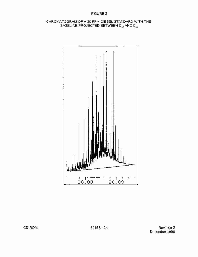
7.7.2.1 For the analysis of DROs, sum the area of all peaks eluting between C10
and C . This area is generated by projecting a horizontal baseline between the retention28
times of C and C . 10 28
7.7.2.2 Because the chromatographic conditions employed for DRO analysiscan result in significant column bleed and a resulting rise in the baseline, it is appropriateto perform a subtraction of the column bleed from the area of the DRO chromatogram.In order to accomplish this subtraction, a methylene chloride blank should be analyzedduring each 12-hour analytical shift during which samples are analyzed for DROs. Thearea of this chromatogram is measured in the same fashion as is used for samples (seeSec. 7.7.2.1), by projecting a horizontal baseline across the retention time range forDROs. This area is then subtracted from the area measured for the sample and thedifference in areas is used to calculate the DRO concentration, using the equations inMethod 8000.
CD-ROM 8015B - 13 Revision 2December 1996
7.7.2.3 For the analysis of GROs, sum the area of all peaks eluting between 2-methylpentane and 1,2,4-trimethyl benzene. This area is used to calculate the GROconcentration, using the equations in Method 8000. Column bleed subtraction is notgenerally required for GRO analysis.
7.7.3 Refer to Method 8000, Sec. 7.0 for calculation formulae. The formulae coverexternal and internal standard calibration, aqueous and non-aqueous samples and linear andnon-linear calibration curves.
7.8 Screening
7.8.1 Method 8015 with single-point calibration can also be used for GC/FID screeningin order to reduce instrument down-time when highly contaminated samples are analyzed usingGC/MS (e.g., Methods 8260 and 8270).
7.8.2 The same configuration of introduction device interfaced to the GC/MS may beutilized for the GC/FID or alternative configurations are acceptable.
7.8.3 Establish that the system response and chromatographic retention times arestable. Analyze the high-point GC/MS calibration standard.
7.8.4 Analyze samples or sample extracts. Compare peak heights in the samplechromatograms with the high-point standard to establish that no compound with the sameretention time as a target analyte exceeds the calibration range. However, the FID is muchless sensitive to halogenated compounds than the GC/MS system, therefore, the abovecomparison is not an absolute certainty.
7.8.5 It is recommended that the high-point standard should be run at least every 12hours to confirm the stability of instrument response and chromatographic retention times.However, there is no QC requirement for screening.
7.9 Instrument Maintenance
7.9.1 Injection of sample extracts from waste sites often leaves a high boiling residuein: the injection port area, splitters when used, and the injection port end of thechromatographic column. This residue effects chromatography in many ways (i.e., peak tailing,retention time shifts, analyte degradation, etc.) and, therefore, instrument maintenance is veryimportant. Residue buildup in a splitter may limit flow through one leg and therefore changethe split ratios. If this occurs during an analytical run, the quantitative data may be incorrect.Proper cleanup techniques will minimize the problem and instrument QC will indicate wheninstrument maintenance is required.
7.9.2 Suggested chromatograph maintenance
Corrective measures may require any one or more of the following remedial actions. Alsosee Sec. 7.0 in Method 8000 for additional guidance on corrective action for capillary columnsand the injection port.
7.9.2.1 Splitter connections - For dual columns which are connected using apress-fit Y-shaped glass splitter or a Y-shaped fused-silica connector, clean anddeactivate the splitter or replace with a cleaned and deactivated splitter. Break off thefirst few inches (up to one foot) of the injection port side of the column. Remove the
CD-ROM 8015B - 14 Revision 2December 1996
columns and solvent backflush according to the manufacturer's instructions. If theseprocedures fail to eliminate the degradation problem, it may be necessary to deactivatethe metal injector body and/or replace the columns.
7.9.2.2 Column rinsing - The column should be rinsed with several columnvolumes of an appropriate solvent. Both polar and nonpolar solvents are recommended.Depending on the nature of the sample residues expected, the first rinse might be water,followed by methanol and acetone; methylene chloride is a satisfactory final rinse and insome cases may be the only solvent required. The column should then be filled withmethylene chloride and allowed to remain flooded overnight to allow materials within thestationary phase to migrate into the solvent. The column is then flushed with freshmethylene chloride, drained, and dried at room temperature with a stream of ultrapurenitrogen passing through the column.
8.0 QUALITY CONTROL
8.1 Refer to Chapter One and Method 8000 for specific quality control (QC) procedures.Quality control procedures to ensure the proper operation of the various sample preparation and/orsample introduction techniques can be found in Methods 3500 and 5000. Each laboratory shouldmaintain a formal quality assurance program. The laboratory should also maintain records todocument the quality of the data generated.
8.2 Quality control procedures necessary to evaluate the GC system operation are found inMethod 8000, Sec. 7.0 and include evaluation of retention time windows, calibration verification andchromatographic analysis of samples.
8.3 Initial Demonstration of Proficiency - Each laboratory must demonstrate initial proficiencywith each sample preparation and determinative method combination it utilizes, by generating dataof acceptable accuracy and precision for target analytes in a clean matrix. The laboratory must alsorepeat the following operations whenever new staff are trained or significant changes ininstrumentation are made. See Method 8000, Sec. 8.0 for information on how to accomplish thisdemonstration.
8.4 Sample Quality Control for Preparation and Analysis - The laboratory must also haveprocedures for documenting the effect of the matrix on method performance (precision, accuracy,and detection limit). At a minimum, this includes the analysis of QC samples including a methodblank, a matrix spike, a duplicate, and a laboratory control sample (LCS) in each analytical batch andthe addition of surrogates to each field sample and QC sample.
8.4.1 Documenting the effect of the matrix should include the analysis of at least onematrix spike and one duplicate unspiked sample or one matrix spike/matrix spike duplicate pair.The decision on whether to prepare and analyze duplicate samples or a matrix spike/matrixspike duplicate must be based on a knowledge of the samples in the sample batch. If samplesare expected to contain target analytes, then laboratories may use one matrix spike and aduplicate analysis of an unspiked field sample. If samples are not expected to contain targetanalytes, laboratories should use a matrix spike and matrix spike duplicate pair.
8.4.2 A Laboratory Control Sample (LCS) should be included with each analytical batch.The LCS consists of an aliquot of a clean (control) matrix similar to the sample matrix and ofthe same weight or volume. The LCS is spiked with the same analytes at the sameconcentrations as the matrix spike. When the results of the matrix spike analysis indicate a
CD-ROM 8015B - 15 Revision 2December 1996
potential problem due to the sample matrix itself, the LCS results are used to verify that thelaboratory can perform the analysis in a clean matrix.
8.4.3 See Method 8000, Sec. 8.0 for the details on carrying out sample quality controlprocedures for preparation and analysis.
8.5 Surrogate recoveries - The laboratory must evaluate surrogate recovery data fromindividual samples versus the surrogate control limits developed by the laboratory. See Method8000, Sec. 8.0 for information on evaluating surrogate data and developing and updating surrogatelimits.
8.6 It is recommended that the laboratory adopt additional quality assurance practices for usewith this method. The specific practices that are most productive depend upon the needs of thelaboratory and the nature of the samples. Whenever possible, the laboratory should analyzestandard reference materials and participate in relevant performance evaluation studies.
9.0 METHOD PERFORMANCE
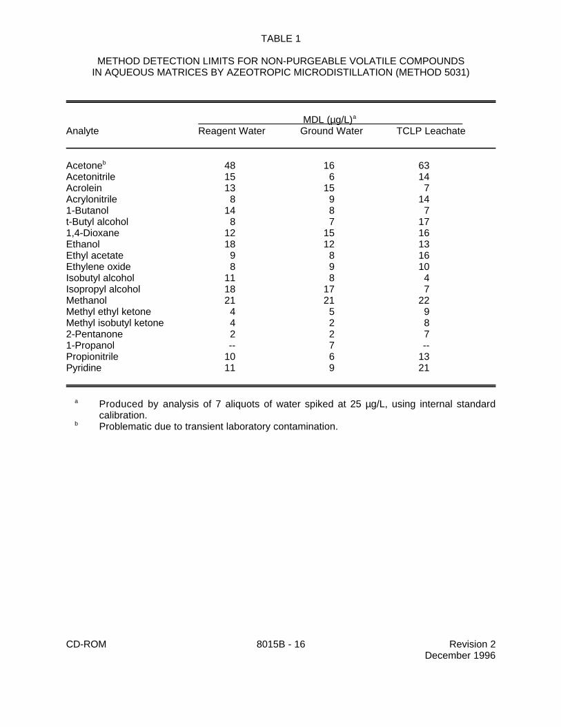
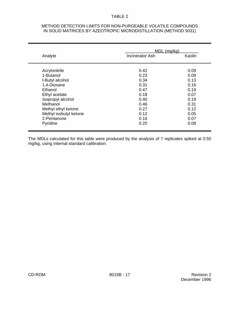
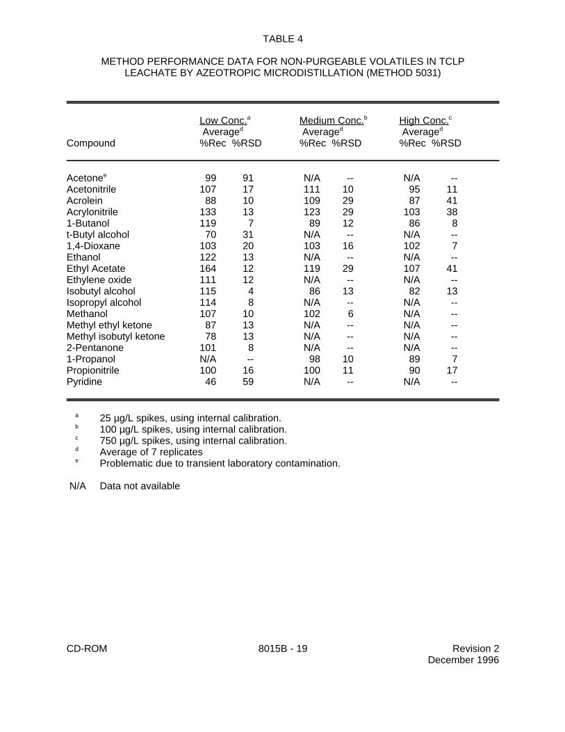
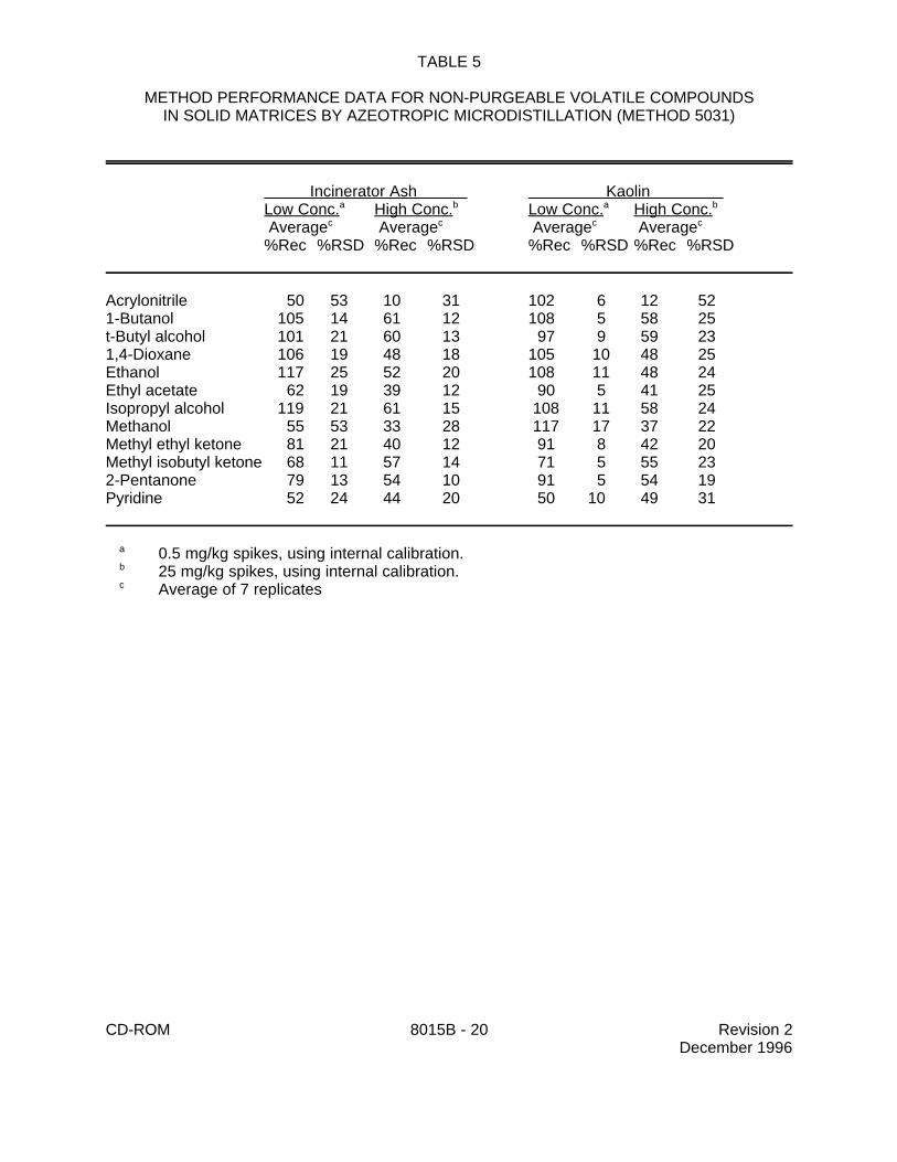
9.1 Specific method performance information for non-purgeable volatiles prepared using theazeotropic microdistillation technique from Method 5031 is included in Tables 1, 3 and 4 for aqueousmatrices and in Tables 2 and 5 for solid matrices.
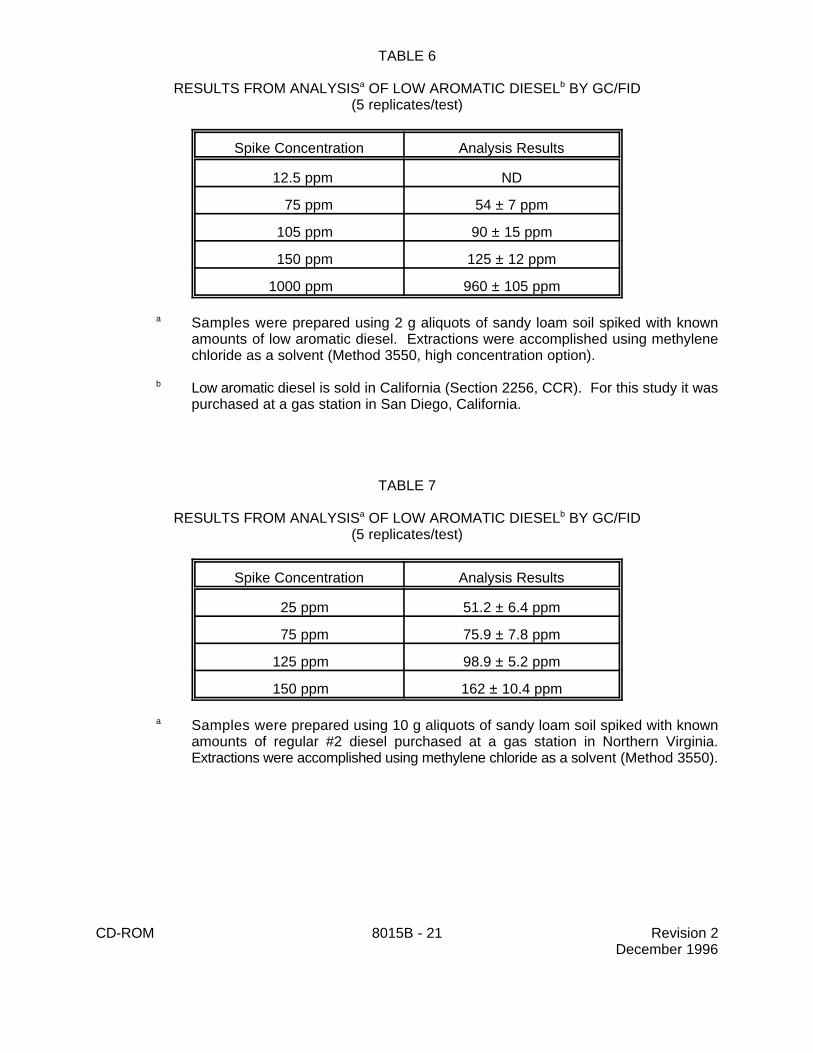
9.2 Specific method performance information is provided for diesel fuel spiked into soil inTables 6 and 7.
10.0 REFERENCES
1. Bellar, T.A., and J.J. Lichtenberg. "Determining Volatile Organics at Microgram-per-Liter Levelsby Gas Chromatography", J. Amer. Water Works Assoc., 66(12), pp. 739-744 (1974).
2. Bellar, T.A., and J.J. Lichtenberg. "Semi-Automated Headspace Analysis of Drinking Watersand Industrial Waters for Purgeable Volatile Organic Compounds", in Van Hall, ed.,Measurement of Organic Pollutants in Water and Wastewater, ASTM STP 686, pp. 108-129,1979.
3. Development and Application of Test Procedures for Specific Organic Toxic Substances inWastewaters: Category 11 - Purgeables and Category 12 - Acrolein, Acrylonitrile, andDichlorodifluoromethane, Report for EPA Contract 68-03-2635.
4. Bruce, M.L., R.P. Lee, and M.W. Stevens. "Concentration of Water Soluble Volatile OrganicCompounds from Aqueous Samples by Azeotropic Microdistillation", Environ. Sci. Technol.1992, 26, 160-163.
5. Tsang, S.F., N. Chau, P.J. Marsden, and K.R. Carter. "Evaluation of the EnSys PETRO RISckit for TPH", Report for Ensys, Inc., Research Triangle Park, NC, 27709, 1992.
6. "Interlaboratory Study of Three Methods for Analyzing Petroleum Hydrocarbons in Soils," APIPublication Number 4599, American Petroleum Institute, March 1994.
CD-ROM 8015B - 16 Revision 2December 1996
TABLE 1
METHOD DETECTION LIMITS FOR NON-PURGEABLE VOLATILE COMPOUNDSIN AQUEOUS MATRICES BY AZEOTROPIC MICRODISTILLATION (METHOD 5031)
RESULTS FROM ANALYSIS OF LOW AROMATIC DIESEL BY GC/FIDa b
(5 replicates/test)
Spike Concentration Analysis Results
12.5 ppm ND
75 ppm 54 ± 7 ppm
105 ppm 90 ± 15 ppm
150 ppm 125 ± 12 ppm
1000 ppm 960 ± 105 ppm
Samples were prepared using 2 g aliquots of sandy loam soil spiked with knowna
amounts of low aromatic diesel. Extractions were accomplished using methylenechloride as a solvent (Method 3550, high concentration option).
Low aromatic diesel is sold in California (Section 2256, CCR). For this study it wasb
purchased at a gas station in San Diego, California.
TABLE 7
RESULTS FROM ANALYSIS OF LOW AROMATIC DIESEL BY GC/FIDa b
(5 replicates/test)
Spike Concentration Analysis Results
25 ppm 51.2 ± 6.4 ppm
75 ppm 75.9 ± 7.8 ppm
125 ppm 98.9 ± 5.2 ppm
150 ppm 162 ± 10.4 ppm
Samples were prepared using 10 g aliquots of sandy loam soil spiked with knowna
amounts of regular #2 diesel purchased at a gas station in Northern Virginia.Extractions were accomplished using methylene chloride as a solvent (Method 3550).
CD-ROM 8015B-22 Revision 2December 1996
FIGURE 1
CHROMATOGRAM OF A 300 PPM GASOLINE STANDARD
CD-ROM 8015B - 23 Revision 2December 1996
FIGURE 2
CHROMATOGRAM OF A 30 PPM DIESEL STANDARD
CD-ROM 8015B - 24 Revision 2December 1996
FIGURE 3
CHROMATOGRAM OF A 30 PPM DIESEL STANDARD WITH THE BASELINE PROJECTED BETWEEN C AND C10 18
CD-ROM 8015B - 25 Revision 2December 1996
FIGURE 4
CHROMATOGRAM OF SEVERAL NONPURGEABLE VOLATILE COMPOUNDS INSPIKED REAGENT WATER USING AZEOTROPIC MICRODISTILLATION (METHOD 5031)
CD-ROM 8015B - 26 Revision 2December 1996
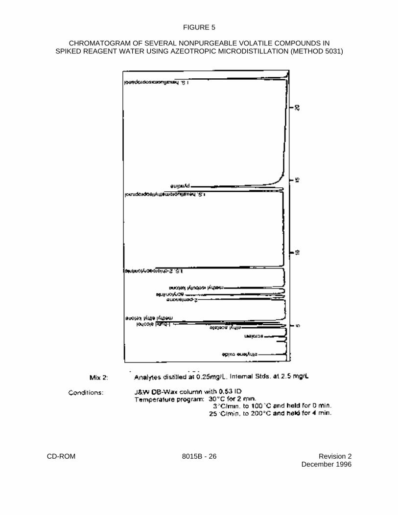
FIGURE 5
CHROMATOGRAM OF SEVERAL NONPURGEABLE VOLATILE COMPOUNDS INSPIKED REAGENT WATER USING AZEOTROPIC MICRODISTILLATION (METHOD 5031)