Method of Statement for CT TOTAL 5 PAGES (Including Cover) PROJECT NAME : Khabat Thermal Power Plant Units 1&2 Purpose ☐ For Information ☐ For Review ☒ For Approval ☐ For Construction ☐ As-Built DOCUMENT NO. : KP-00+++-CY712-B7209 TITLE : Instrument Cabinet and Junction Box OWNER : Ministry of Electricity (MOE) of Kurdistan Regional Government A 01.11.2015 For Approval U.K. C.A. M.E.K. M.Ö. Rev. No. DATE DESCRIPTION PREPARED CHECKED REVIEWED APPROVED GAMA POWER SYSTEMS ENG &CONTRACTING,INC. Owner Ministry of Electricity (MOE) of Kurdistan Regional Government Contractor POSCO ENGINEERING & CONSTRUCTION CO., LTD.
Transcript
Method of Statement forCT
TOTAL 5 PAGES (Including Cover)
PROJECT NAME : Khabat Thermal Power Plant Units 1&2Purpose☐ For Information
☐ For Review
☒ For Approval
☐ For Construction
☐ As-Built
DOCUMENT NO. : KP-00+++-CY712-B7209
TITLE : Instrument Cabinet and Junction Box
OWNER : Ministry of Electricity (MOE) of Kurdistan Regional Government
A 01.11.2015 For Approval U.K. C.A. M.E.K. M.Ö.
Rev.No. DATE DESCRIPTION
PREPARED CHECKED REVIEWED APPROVEDGAMA POWER SYSTEMS ENG
&CONTRACTING,INC.Owner
Ministry of Electricity (MOE)of Kurdistan Regional Government
Contractor
POSCO ENGINEERING& CONSTRUCTION CO., LTD.
Main Subcontractor
GAMA POWER SYSTEMS ENGINEERING & CONTRACTING,INC.
SUMMARY:
1. PURPOSE OF TESTS................................................................................................................32. REFERENCE DOCUMENT.....................................................................................................33. SCOPE.........................................................................................................................................34. TERMINOLOGY.......................................................................................................................35. EQUIPMENT UNDER TEST...................................................................................................36. TEST EQUIPMENT REQUIRED............................................................................................37. GENERAL INSPECTION.........................................................................................................47.1. MECHANICAL CHECKS....................................................................................................47.2. ELECTRICAL CHECKS......................................................................................................48. INSULATION RESISTANCE TEST FOR CT.......................................................................49. CIRCUIT RESISTANCE MEASURES FOR CT...................................................................610. PRIMARY CURRENT TEST FOR CT...............................................................................610.1. TRANSFORMERS TURNS RATIO & POLARITY TESTS............................................710.2. CONSUMPTION – POWER (BURDEN) FOR CT............................................................811. SATURATION CURVE FOR CT......................................................................................1012. SPECIAL SAFETY PRECAUTION..................................................................................1113. INSULATION RESISTANCE TEST FOR VT.................................................................1214. POLARITY TEST FOR VT................................................................................................1315. TRANSFORMER TURNS RATIO TEST FOR VT.........................................................1416. RECORDING OF INSPECTION AND TEST DATA......................................................15
KHABAT TPP UNITS 1&2
Method Statement forElectrical and I&C Panels Installation
Doc. No KP-00+++-CY712-B7204Rev. No. APage Sayfa 3 / 11
1. PURPOSE OF TESTS
Before testing the relaying, metering and measuring equipment, it is necessary to check the associated Grounding Resistor Panel.
2. REFERENCE DOCUMENT
Electrical drawing N°
3. SCOPE
All working sites
4. TERMINOLOGY
No applicable.
5. EQUIPMENT UNDER TEST
The concerned equipment are all types of current transformers.
6. TEST EQUIPMENT REQUIRED
- Bidirectional miliammeter- RS polarity test set- Voltmeters- Ammeters- Clamp-on-ammeter- 1 primary test supply- 1 miliohmmeter or digital volt-ohm-miliammeter- Autotransformer- 1 step-up transformer- 1 Megohmmeter 500 V. - 5 kV
7. GENERAL INSPECTION
7.1. MECHANICAL CHECKS
- General visual inspection (porcelain insulators, etc...)- Check the connections for looseness and stressed terminals
- Check the oil level and inspect for leakage (where applicable)- Check terminal markings and nameplate ratings- Check that primary terminals P1 and P2 are directed in compliance with the
drawing
7.2. ELECTRICAL CHECKS
- Check the coupling strips (if applicable) for correct positioning
- Check the ground system on secondary side
KHABAT TPP UNITS 1&2
Method Statement forElectrical and I&C Panels Installation
Doc. No KP-00+++-CY712-B7204Rev. No. APage Sayfa 4 / 11
- Check for phase identification and secondary circuit continuity
- Check the assignment of the « measuring » and « relaying » secondaries
8. INSULATION RESISTANCE TEST FOR CT
Between primary winding and ground
Perform the test using a Megger set for the appropriate range.
Performs the test on the primary winding of each phase, with the primary windings of the other phases temporarily connected to ground
The secondary windings are connected together and to ground.Apply the test voltage for 1 minute. The test voltage varies with the ratings of the equipment under test
LV: 6 to 100 volts (direct current)
MV: 100 to 1000 volts (direct current)
HV : 1000 to 5000 volts (direct current)
Between secondary winding and ground
Successively measure the insulation resistance between each winding and the other windings connected to ground. Apply 500 VDC for one minute.
KHABAT TPP UNITS 1&2
Method Statement forElectrical and I&C Panels Installation
Doc. No KP-00+++-CY712-B7204Rev. No. APage Sayfa 5 / 11
9. CIRCUIT RESISTANCE MEASURES FOR CT
Concerning some types of relays such as differential relays, high impedance relays, the secondary side and loop resistance measures must be done.
10.PRIMARY CURRENT TEST FOR CT
The measurements are performed with single-phase current, with the secondary loops in final condition (relays, meters, etc...) and grounded.
For current measurement, use a clamp-on-ammeter to avoid opening the secondary circuits.
Measure the voltage (mV) across the primary winding as a check that the primary winding is in correct operating condition and that the connections are correct (very low contact resistance).
KHABAT TPP UNITS 1&2
Method Statement forElectrical and I&C Panels Installation
Doc. No KP-00+++-CY712-B7204Rev. No. APage Sayfa 6 / 11
The following checks can be performed.
10.1. TRANSFORMERS TURNS RATIO & POLARITY TESTSMeasure the primary and secondary currents. Test equipment compares primary and secondary current values and also checks polarity itself.
How to check The Turn Ratio & Polarity by CPC 100
CPC 100 Result Monitoring 10.2. CONSUMPTION – POWER (BURDEN) FOR CT
Check the secondary loop consumption using the same set-up.
Use a clamp-on-ammeter to measure the current. Measure the voltage directly across the secondary winding.
KHABAT TPP UNITS 1&2
Method Statement forElectrical and I&C Panels Installation
Doc. No KP-00+++-CY712-B7204Rev. No. APage Sayfa 7 / 11
The power can thus be established:P(VA) = U(V) x I(A)
With three-phase current and for a similar circuit, the readings should be almost identical for each phase. If the readings show excessive differences, check all the circuit connections to eliminate contact resistance.The loop resistance can be calculated or measured using a milliohmmeter.
NOTE:The primary current tests are performed following the current transformer, relaying, metering and measuring equipment tests. These tests are the last tests performed on secondary windings. Check that the unused windings are shorted.
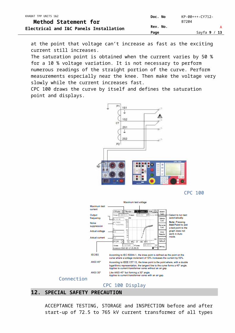
11.SATURATION CURVE FOR CTDetermine the knee voltage.This test performs an automatic injection of a exciting voltage of up to 2 kV to the current transformer’s secondary side. Test equipment increases voltage slowly and at the same time the exciting current also increases. The saturation point is defined at the point that voltage can’t increase as fast as the exciting current still increases.The saturation point is obtained when the current varies by 50 % for a 10 % voltage variation. It is not necessary to perform numerous readings of the straight portion of the curve. Perform measurements especially near the knee. Then make the voltage very slowly while the current increases fast.CPC 100 draws the curve by itself and defines the saturation point and displays.
KHABAT TPP UNITS 1&2
Method Statement forElectrical and I&C Panels Installation
Doc. No KP-00+++-CY712-B7204Rev. No. APage Sayfa 8 / 11
CPC 100 Connection
CPC 100 Display12.SPECIAL SAFETY PRECAUTION
ACCEPTANCE TESTING, STORAGE and INSPECTION before and after start-up of 72.5 to 765 kV current transformer of all types
Connections
When work is performed on an operating substation bay, a rather high current can be induced by the adjacent bays in the loop made up by the ground connections, which can flow through the current transformer primary windings.
Opening a CT secondary winding in the above configuration may cause over-voltages greater than the normally permissible values, which can damage insulation.
Therefore, care should be taken to avoid opening secondary circuits and especially:
KHABAT TPP UNITS 1&2
Method Statement forElectrical and I&C Panels Installation
Doc. No KP-00+++-CY712-B7204Rev. No. APage Sayfa 9 / 11
- when connecting a CT to an operating substation, connect the secondary circuits and check for continuity before connecting the primary winding
- when performing work on the secondary circuits of a CT of an operating substation bay, short out the CT secondary windings upstream the point of intervention before opening the circuit.
13.INSULATION RESISTANCE TEST FOR VT
To obtain values as close as possible to the manufacturer’s specifications, the insulators must be very clean.
Select the Megger range corresponding to the ratings of the equipment under test :
LV: 6 to 100 volts (direct current)MV: 100 to 1000 volts (direct current)HV: 1000 to 5000 volts (direct current)
The theoretical values are furnished by the manufacturer.
Measurements between primary and secondary
Measurements between primary and ground
Measurement between secondaries and between secondary and ground
KHABAT TPP UNITS 1&2
Method Statement forElectrical and I&C Panels Installation
Doc. No KP-00+++-CY712-B7204Rev. No. APage Sayfa 10 / 11
14.POLARITY TEST FOR VT
The polarity is checked using the kick method (application of direct current) and check of deflection on a bidirectional milliammeter.
This test is also used to check primary and secondary circuit continuity.
- When switch K is closed, the milliammeter pointer deflects upscale.
- When the circuit is opened, the milliammeter pointer deflects in the negative direction.
15.TRANSFORMER TURNS RATIO TEST FOR VT
A variable AC source is applied on the primary side. The primary and secondary voltages are measured to determine the ratio V2 / V1.
KHABAT TPP UNITS 1&2
Method Statement forElectrical and I&C Panels Installation
Doc. No KP-00+++-CY712-B7204Rev. No. APage Sayfa 11 / 11
CPC 100 Display
16.RECORDING OF INSPECTION AND TEST DATA
The results of the checks and measurements made during the field tests shall be recorded on the test forms: