13
METHOD STATEMENT Sika® FloorJoint S
METHOD STATEMENT Sika® FloorJoint S
2/13
Table of Contents 1 SCOPE 3
2 PRODUCT 3 2.1 Sika® FloorJoint S 3
3 SUBSTRATE REQUIREMENTS 3
4 Preparation of the Substrate 3 4.1 Mapping of the joint panels on the floor for the saw cuts 3 4.2 Execution of the saw cuts 4 4.3 To chisel out 5 4.4 Removing of possibly built-in metal profiles 5 4.5 Cleaning and preparation of the cut-out / Substrate 5
5 APPLICATION 6 5.1 Pre-assembling of the joint panels 6 5.2 Placing of a edge strip in the construction joint 7 5.3 Application of the adhesive Sikadur®-31 High-Mod Gel in the cut-out 8 5.4 Application of the Adhesive Sikadur®-31 High-Mod Gel in on the panel 9 5.5 Installation of Sika® FloorJoint S 9 5.6 Plastering of the edges 10 5.7 Grinding of the joint panel 10 5.8 Coating of the joint panel 11
6 HEALTH & SAFETY RECOMMENDATIONS 12 6.1 Personal protection 12
7 LIMITATIONS 12
8 ENVIRONMENT 12 8.1 Cleaning of tools / Mixing equipment 12 8.2 Waste disposal 13
9 LEGAL NOTES 13
Method Statement Sika® FloorJoint S
3/13
1 SCOPE This method statement describes the step by step procedure of the installation of the floor joint panels Sika®FloorJoint S in order to provide all needed information for a proper installation.
2 PRODUCT
2.1 SIKA® FLOORJOINT S
Sika® FloorJoint S is a prefabricated, carbon-fiber-reinforced polymer composite panel with high physical properties. Because of the waved joint design an improved load distribution is achieved. Sika® FloorJoint S is the standard panel for new build and refurbishment of joints for concrete screeds with normal up to medium heavy wear; e.g. warehouses etc.
3 SUBSTRATE REQUIREMENTS Please refer to the Method Statement “Evaluation and Preparation of Surfaces for Flooring Systems”
4 PREPARATION OF THE SUBSTRATE
4.1 MAPPING OF THE JOINT PANELS ON THE FLOOR FOR THE SAW CUTS
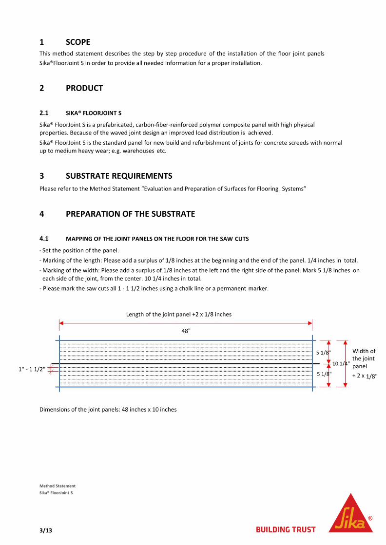
- Set the position of the panel. - Marking of the length: Please add a surplus of 1/8 inches at the beginning and the end of the panel. 1/4 inches in total. - Marking of the width: Please add a surplus of 1/8 inches at the left and the right side of the panel. Mark 5 1/8 inches on
each side of the joint, from the center. 10 1/4 inches in total. - Please mark the saw cuts all 1 - 1 1/2 inches using a chalk line or a permanent marker.
Dimensions of the joint panels: 48 inches x 10 inches
Method Statement Sika® FloorJoint S
Length of the joint panel +2 x 1/8 inches
48"
5 1/8"
10 1/4" 1" - 1 1/2"
5 1/8"
Width of the joint panel + 2 x 1/8"
4/13
4.2 EXECUTION OF THE SAW CUTS
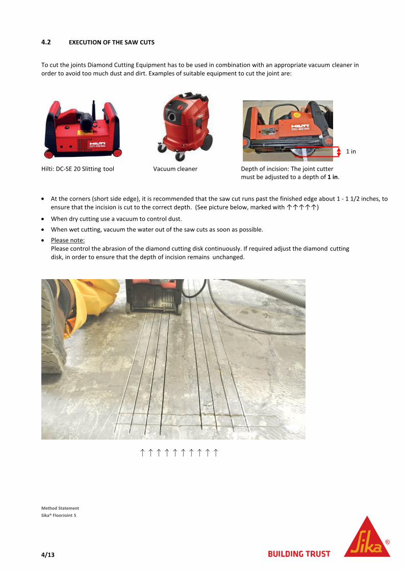
To cut the joints Diamond Cutting Equipment has to be used in combination with an appropriate vacuum cleaner in order to avoid too much dust and dirt. Examples of suitable equipment to cut the joint are:
Hilti: DC-SE 20 Slitting tool Vacuum cleaner
• At the corners (short side edge), it is recommended that the saw cut runs past the finished edge about 1 - 1 1/2 inches, toensure that the incision is cut to the correct depth. (See picture below, marked with ↑↑↑↑↑)
• When dry cutting use a vacuum to control dust.• When wet cutting, vacuum the water out of the saw cuts as soon as possible.
• Please note:Please control the abrasion of the diamond cutting disk continuously. If required adjust the diamond cuttingdisk, in order to ensure that the depth of incision remains unchanged.
↑↑↑↑↑↑↑↑↑↑
Method Statement Sika® FloorJoint S
1 in
Depth of incision: The joint cutter must be adjusted to a depth of 1 in.
5/13
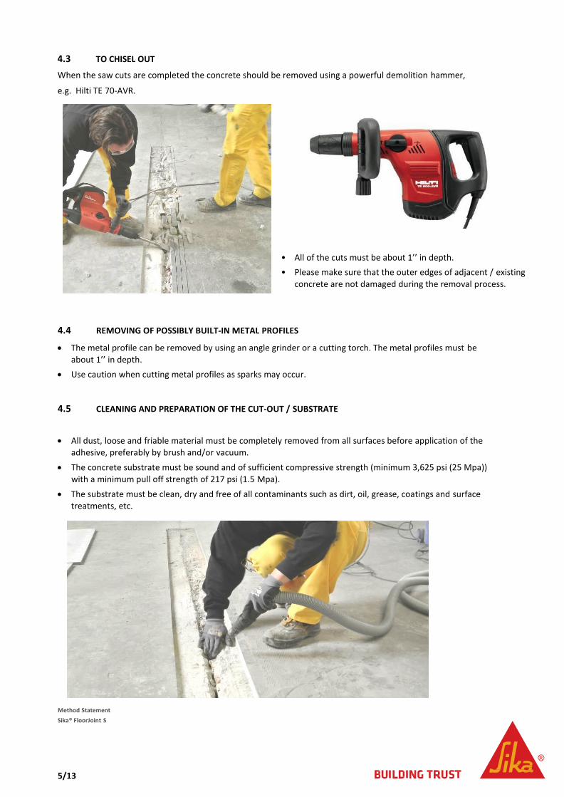
4.3 TO CHISEL OUT
When the saw cuts are completed the concrete should be removed using a powerful demolition hammer,
e.g. Hilti TE 70-AVR.
• All of the cuts must be about 1’’ in depth.• Please make sure that the outer edges of adjacent / existing
concrete are not damaged during the removal process.
4.4 REMOVING OF POSSIBLY BUILT-IN METAL PROFILES
• The metal profile can be removed by using an angle grinder or a cutting torch. The metal profiles must beabout 1’’ in depth.
• Use caution when cutting metal profiles as sparks may occur.
4.5 CLEANING AND PREPARATION OF THE CUT-OUT / SUBSTRATE
• All dust, loose and friable material must be completely removed from all surfaces before application of theadhesive, preferably by brush and/or vacuum.
• The concrete substrate must be sound and of sufficient compressive strength (minimum 3,625 psi (25 Mpa))with a minimum pull off strength of 217 psi (1.5 Mpa).
• The substrate must be clean, dry and free of all contaminants such as dirt, oil, grease, coatings and surfacetreatments, etc.
Method Statement Sika® FloorJoint S
6/13
5 APPLICATION
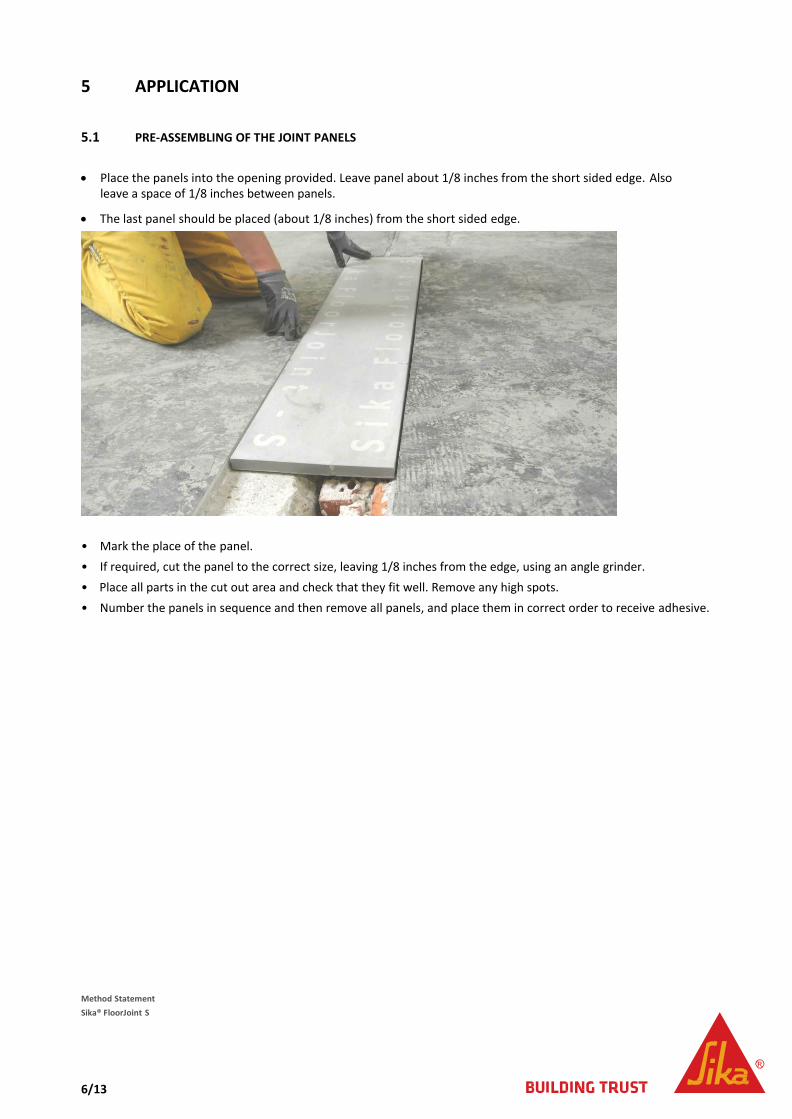
5.1 PRE-ASSEMBLING OF THE JOINT PANELS
• Place the panels into the opening provided. Leave panel about 1/8 inches from the short sided edge. Alsoleave a space of 1/8 inches between panels.
• The last panel should be placed (about 1/8 inches) from the short sided edge.
• Mark the place of the panel.• If required, cut the panel to the correct size, leaving 1/8 inches from the edge, using an angle grinder.• Place all parts in the cut out area and check that they fit well. Remove any high spots.• Number the panels in sequence and then remove all panels, and place them in correct order to receive adhesive.
Method Statement Sika® FloorJoint S

7/13
5.2 PLACING OF AN EDGE STRIP IN THE CONSTRUCTION JOINT In the construction joint, a screed edge stripping (out of a foam profile) must be placed as it is displayed below. This is an essential measure in order to allow movement between the two plates of the joint panel.
Axial position of the edge stripping in the joint. Adjusting the height of the stripping using adjustable trowel
Screed edge stripping supplied in rolls of 55 yards. Height: 3 - 4 in, thickness 1/4 in.
Adjustable trowel for even distribution of the adhesive or to adjust the heights.
Method Statement Sika® FloorJoint S
Duct tape as a release point Sika® FloorJoint S
Adhesive: Sikadur®-31 Hi-Mod Gel Screed edge stripping

8/13
5.3 APPLICATION OF THE ADHESIVE SIKADUR®-31 Hi-Mod Gel IN THE CUT-OUT
• The adhesive Sikadur®-31 Hi-Mod Gel has to be mixed according to the product data sheet• The adhesive has to be applied in the cut-out evenly so that the installed edge stripping will not be covered by
the adhesive.
• In order to allow for movement of the joint after the installation, it is mandatory that both sides of the panel areseparated. For a proper separation, tape is fixed at the bottom side of the panel. Don’t remove it!
• For an even distribution of the adhesive use an adjustable trowel
Axial position of the foam strip in contact with the masking tape which has the function of a “release agent”.
Method Statement Sika® FloorJoint S
Distribution of Sikadur®-31 Hi-Mod Gel in the cut-out by using the adjustable trowel in order to distribute the adhesive.
The trowel hast to be adjusted to 3/4 in

9/13
5.4 APPLICATION OF THE ADHESIVE SIKADUR®-31 Hi-Mod Gel ON THE PANEL
In order to avoid entrapped air, the adhesive has to be applied on the bottom of the panel using a toothed trowel.
5.5 INSTALLATION OF SIKA® FLOORJOINT S
• Install the joint panel into the wet adhesive bed.• Press or pound on the panel in order to ensure that the profile is in contact with all the adhesives!• Please ensured that no voids occur under the joint panel!• Depending on the floor unevenness, the joint panel should be slightly lower or equal to the adjacent areas in
order to grind the profile after the adhesive cures. Grind the cured adhesive to the level of the adjacent floor.
Method Statement Sika® FloorJoint S

10/13
5.6 PLASTERING OF THE EDGES
• Using a spatula or margin trowel, seal the edges so that no voids remain.• The joints must be free of cavities.• Remove excess adhesive, in order to reduce grinding after it cures.
5.7 GRINDING OF THE JOINT PANEL
• The adhesive must be fully cured before the grinding can be completed.• With the help of a diamond disk grinder a seamless transition between the two bottom plates has to completed.• Grind using large circular movements, in order to avoid grinding marks or holes.• Maximum 1/16 inch grind!• Important: The evenness has to be controlled regularly using a level or straight edge.
Method Statement Sika® FloorJoint S
11/13
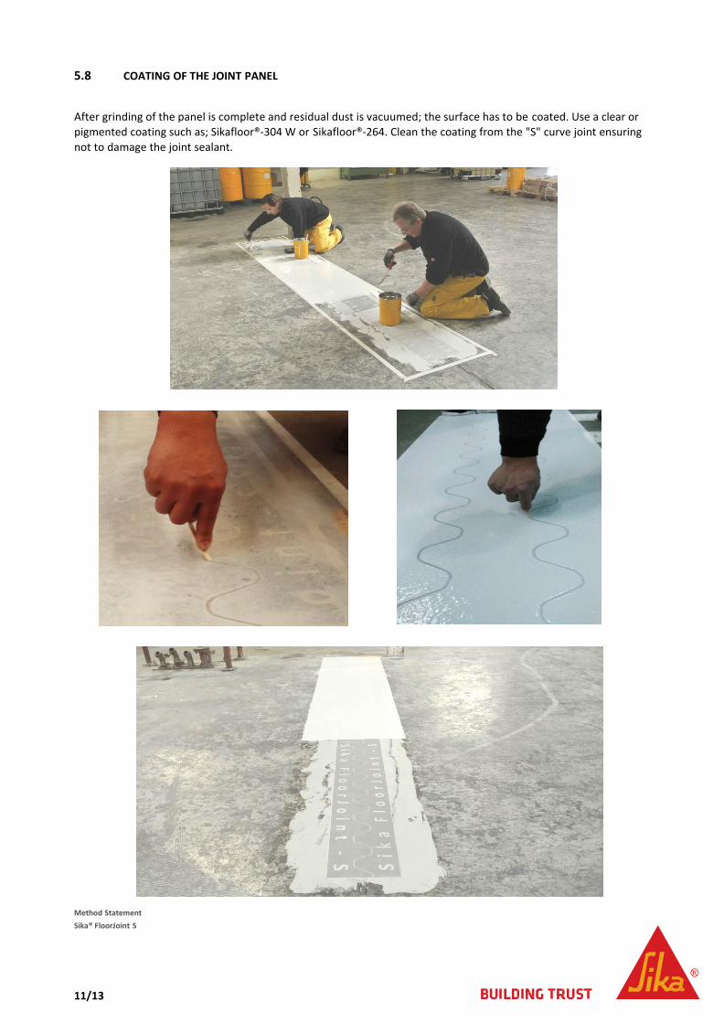
5.8 COATING OF THE JOINT PANEL
After grinding of the panel is complete and residual dust is vacuumed; the surface has to be coated. Use a clear or pigmented coating such as; Sikafloor®-304 W or Sikafloor®-264. Clean the coating from the "S" curve joint ensuring not to damage the joint sealant.
Method Statement Sika® FloorJoint S
12/13
6 HEALTH & SAFETY RECOMMENDATIONS
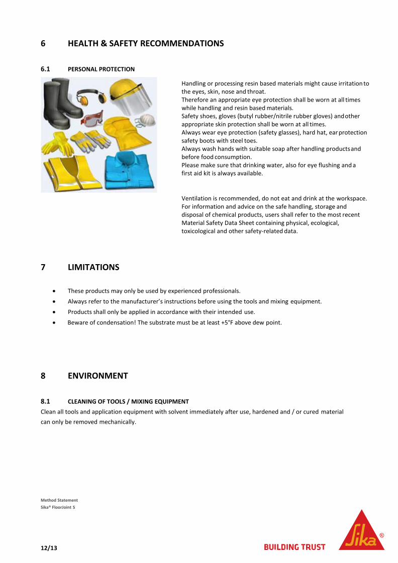
6.1 PERSONAL PROTECTION
Handling or processing resin based materials might cause irritation to the eyes, skin, nose and throat. Therefore an appropriate eye protection shall be worn at all times while handling and resin based materials. Safety shoes, gloves (butyl rubber/nitrile rubber gloves) and other appropriate skin protection shall be worn at all times. Always wear eye protection (safety glasses), hard hat, ear protection safety boots with steel toes. Always wash hands with suitable soap after handling products and before food consumption. Please make sure that drinking water, also for eye flushing and a first aid kit is always available.
Ventilation is recommended, do not eat and drink at the workspace. For information and advice on the safe handling, storage and disposal of chemical products, users shall refer to the most recent Material Safety Data Sheet containing physical, ecological, toxicological and other safety-related data.
7 LIMITATIONS
• These products may only be used by experienced professionals.• Always refer to the manufacturer’s instructions before using the tools and mixing equipment.• Products shall only be applied in accordance with their intended use.
• Beware of condensation! The substrate must be at least +5°F above dew point.
8 ENVIRONMENT
8.1 CLEANING OF TOOLS / MIXING EQUIPMENT Clean all tools and application equipment with solvent immediately after use, hardened and / or cured material can only be removed mechanically.
Method Statement Sika® FloorJoint S
13/13
8.2 WASTE DISPOSAL
Do not empty surplus material into drains; dispose responsibly through licensed waste disposal contractor in accordance with legislation and local / regional authority requirements. Avoid runoff onto soil or into waterways, drains or sewers. FOR DETAILED INFORMATION REFER TO THE MATERIAL SAFETY DATA SHEET
9 LEGAL NOTES The information, and, in particular, the recommendations relating to the application and end-use of Sika® products, are given in good faith based on Sika’s current knowledge and experience of the products when properly stored, handled and applied under normal conditions in accordance with Sika’s recommendations. in practice, the differences in materials, substrates and actual site conditions are such that no warranty in respect of merchantability or of fitness for a particular purpose, nor any liability arising out of any legal relationship whatsoever, can be inferred either from this information, or from any written recommendations, or from any other advice offered. The user of the product must test the products suitability for the intended application and purpose. Sika reserves the right to change the properties of its products. The proprietary rights of third parties must be observed. All orders are accepted subject to our current terms of sale and delivery. Users must always refer to the most recent issue of the local Product Data Sheet for the product concerned, copies of which will be supplied on request.
Method Statement Sika® FloorJoint S


