104
Methodology Guide: Building Applications for Embedded Systems

Methodology Guide:
Building Applicationsfor Embedded Systems

Methodology Guide: Building Applications for Embedded Systems
© 2002 e-SIM Ltd. All rights reserved.
e-SIM Ltd.POB 45002Jerusalem91450Israel
Tel: 972-2-5870770Fax: 972-2-5870773
Information in this manual is subject to change without notice and does not represent a commitment on the part of the vendor. The software described in this manual is furnished under a license agreement and may be used or copied only in accordance with the terms of that agreement. No part of this manual may be reproduced or transmitted in any form or by any means, electronic or mechanical, including photocopying and recording, for any purpose without the express written permission of e-SIM Ltd.
Microsoft, Windows, Windows NT, and DOS are either registered trademarks or trademarks of Microsoft Corporation in the United States and/or other countries. Microsoft Windows Excel is a product of Microsoft Corporation.
Written and produced by e-SIM Ltd.Printed in Israel.
MAN-MethGuide-7.01
iii
Contents
About the Methodology Guide . . . . . . . . . . . . . . . . . . . . . . . . . . . . . . . . . . . . . . . . . . . . . . . . . . . . . . vii
Typographic Conventions Used in this Guide . . . . . . . . . . . . . . . . . . . . . . . . . . . . . . . . . . . . viii
User Assistance from e-SIM . . . . . . . . . . . . . . . . . . . . . . . . . . . . . . . . . . . . . . . . . . . . . . . . . . . . . viii
C H A P T E R 1 : M E T H O D O L O G Y O V E R V I E W . . . . . . . . . . . . . . . . . . . . . . . . . . . . . . . . . . . . . . . . . 1
The Rapid Development Methodology . . . . . . . . . . . . . . . . . . . . . . . . . . . . . . . . . . . . . . . . . . . . . . . .2
Stage 1: Requirements Specification . . . . . . . . . . . . . . . . . . . . . . . . . . . . . . . . . . . . . . . . . . . . . . .4
Stage 2: Architecture Design . . . . . . . . . . . . . . . . . . . . . . . . . . . . . . . . . . . . . . . . . . . . . . . . . . . . . .5
Stage 3: Implementation . . . . . . . . . . . . . . . . . . . . . . . . . . . . . . . . . . . . . . . . . . . . . . . . . . . . . . . . .7
Stage 4: Integration and On-Going Optimization . . . . . . . . . . . . . . . . . . . . . . . . . . . . . . . . . . .8
Stage 5: Final Optimization . . . . . . . . . . . . . . . . . . . . . . . . . . . . . . . . . . . . . . . . . . . . . . . . . . . . . . .8
Stage 6: Acceptance Testing . . . . . . . . . . . . . . . . . . . . . . . . . . . . . . . . . . . . . . . . . . . . . . . . . . . . . . .8
C H A P T E R 2 : R E Q U I R E M E N T S S P E C I F I C A T I O N . . . . . . . . . . . . . . . . . . . . . . . . . . . . . . . . . . . 9
Ref_Design Requirements Specification. . . . . . . . . . . . . . . . . . . . . . . . . . . . . . . . . . . . . . . . . . . . . . .10
MMI Feature Requirements . . . . . . . . . . . . . . . . . . . . . . . . . . . . . . . . . . . . . . . . . . . . . . . . . . . . . .11
C H A P T E R 3 : A R C H I T E C T U R E D E S I G N . . . . . . . . . . . . . . . . . . . . . . . . . . . . . . . . . . . . . . . . . . . 17
Architecture Design Methodology . . . . . . . . . . . . . . . . . . . . . . . . . . . . . . . . . . . . . . . . . . . . . . . . . . .18
Code Generation Considerations . . . . . . . . . . . . . . . . . . . . . . . . . . . . . . . . . . . . . . . . . . . . . . . . . . . .19
Types of Code Generation . . . . . . . . . . . . . . . . . . . . . . . . . . . . . . . . . . . . . . . . . . . . . . . . . . . . . . .19
Interface of User Objects . . . . . . . . . . . . . . . . . . . . . . . . . . . . . . . . . . . . . . . . . . . . . . . . . . . . . . . .21
Implementing Interface in Generated Code . . . . . . . . . . . . . . . . . . . . . . . . . . . . . . . . . . . . . . .24
Code Generation Process . . . . . . . . . . . . . . . . . . . . . . . . . . . . . . . . . . . . . . . . . . . . . . . . . . . . . . . .25
iv
Identifying Components . . . . . . . . . . . . . . . . . . . . . . . . . . . . . . . . . . . . . . . . . . . . . . . . . . . . . . . . . . . 26
Embedded Interface Components. . . . . . . . . . . . . . . . . . . . . . . . . . . . . . . . . . . . . . . . . . . . . . . . 27
Service Components. . . . . . . . . . . . . . . . . . . . . . . . . . . . . . . . . . . . . . . . . . . . . . . . . . . . . . . . . . . . 29
Continuous vs. On-Demand Services. . . . . . . . . . . . . . . . . . . . . . . . . . . . . . . . . . . . . . . . . . . . . 32
Application Modules . . . . . . . . . . . . . . . . . . . . . . . . . . . . . . . . . . . . . . . . . . . . . . . . . . . . . . . . . . . 37
Using Holders to Share Components . . . . . . . . . . . . . . . . . . . . . . . . . . . . . . . . . . . . . . . . . . . . . 38
Creating the Main Application . . . . . . . . . . . . . . . . . . . . . . . . . . . . . . . . . . . . . . . . . . . . . . . . . . 40
Component Functionality . . . . . . . . . . . . . . . . . . . . . . . . . . . . . . . . . . . . . . . . . . . . . . . . . . . . . . . . . . 40
Component Interface . . . . . . . . . . . . . . . . . . . . . . . . . . . . . . . . . . . . . . . . . . . . . . . . . . . . . . . . . . . . . . 41
Interface with the Embedded System . . . . . . . . . . . . . . . . . . . . . . . . . . . . . . . . . . . . . . . . . . . . . 41
Interface Among Full User Objects . . . . . . . . . . . . . . . . . . . . . . . . . . . . . . . . . . . . . . . . . . . . . . . 44
Component Interface Examples . . . . . . . . . . . . . . . . . . . . . . . . . . . . . . . . . . . . . . . . . . . . . . . . . 47
Rapid and System Architecture . . . . . . . . . . . . . . . . . . . . . . . . . . . . . . . . . . . . . . . . . . . . . . . . . . . . . . 51
Task Architecture. . . . . . . . . . . . . . . . . . . . . . . . . . . . . . . . . . . . . . . . . . . . . . . . . . . . . . . . . . . . . . . 51
Inter-Task Communication and Memory Allocation . . . . . . . . . . . . . . . . . . . . . . . . . . . . . . . 51
Rapid Task Priority . . . . . . . . . . . . . . . . . . . . . . . . . . . . . . . . . . . . . . . . . . . . . . . . . . . . . . . . . . . . . 52
Starvation of the System . . . . . . . . . . . . . . . . . . . . . . . . . . . . . . . . . . . . . . . . . . . . . . . . . . . . . . . . 52
UI Required in Different Tasks . . . . . . . . . . . . . . . . . . . . . . . . . . . . . . . . . . . . . . . . . . . . . . . . . . . 52
Timer Integration . . . . . . . . . . . . . . . . . . . . . . . . . . . . . . . . . . . . . . . . . . . . . . . . . . . . . . . . . . . . . . 53
Design Review . . . . . . . . . . . . . . . . . . . . . . . . . . . . . . . . . . . . . . . . . . . . . . . . . . . . . . . . . . . . . . . . . . . . . 54
C H A P T E R 4 : I M P L E M E N T A T I O N . . . . . . . . . . . . . . . . . . . . . . . . . . . . . . . . . . . . . . . . . . . . . . . . . . 55
Setting implementation priorities . . . . . . . . . . . . . . . . . . . . . . . . . . . . . . . . . . . . . . . . . . . . . . . . . . . 56
Implementing Components . . . . . . . . . . . . . . . . . . . . . . . . . . . . . . . . . . . . . . . . . . . . . . . . . . . . . . . . 57
Component Implementation Procedure . . . . . . . . . . . . . . . . . . . . . . . . . . . . . . . . . . . . . . . . . . 57
Implementing Embedded Interface Components . . . . . . . . . . . . . . . . . . . . . . . . . . . . . . . . . . 58
Implementing Services. . . . . . . . . . . . . . . . . . . . . . . . . . . . . . . . . . . . . . . . . . . . . . . . . . . . . . . . . . 59
Implementing the Graphic Display Object. . . . . . . . . . . . . . . . . . . . . . . . . . . . . . . . . . . . . . . . 59
Using Holders. . . . . . . . . . . . . . . . . . . . . . . . . . . . . . . . . . . . . . . . . . . . . . . . . . . . . . . . . . . . . . . . . . 61
Implementation Tips . . . . . . . . . . . . . . . . . . . . . . . . . . . . . . . . . . . . . . . . . . . . . . . . . . . . . . . . . . . . . . . 62
Verification Test . . . . . . . . . . . . . . . . . . . . . . . . . . . . . . . . . . . . . . . . . . . . . . . . . . . . . . . . . . . . . . . 62
Code Generation Messages . . . . . . . . . . . . . . . . . . . . . . . . . . . . . . . . . . . . . . . . . . . . . . . . . . . . . . 63
Modes vs. Conditions. . . . . . . . . . . . . . . . . . . . . . . . . . . . . . . . . . . . . . . . . . . . . . . . . . . . . . . . . . . 63
Managing Priorities. . . . . . . . . . . . . . . . . . . . . . . . . . . . . . . . . . . . . . . . . . . . . . . . . . . . . . . . . . . . . 64
Streamlining Processes . . . . . . . . . . . . . . . . . . . . . . . . . . . . . . . . . . . . . . . . . . . . . . . . . . . . . . . . . . 66

v
Avoiding Processor-Intensive Logic . . . . . . . . . . . . . . . . . . . . . . . . . . . . . . . . . . . . . . . . . . . . . . .66
Blocking Operations and Loops . . . . . . . . . . . . . . . . . . . . . . . . . . . . . . . . . . . . . . . . . . . . . . . . . .67
Objects . . . . . . . . . . . . . . . . . . . . . . . . . . . . . . . . . . . . . . . . . . . . . . . . . . . . . . . . . . . . . . . . . . . . . . . .67
C H A P T E R 5 : O P T I M I Z A T I O N . . . . . . . . . . . . . . . . . . . . . . . . . . . . . . . . . . . . . . . . . . . . . . . . . . . . . . 69
Memory Usage Diagnostic Tools . . . . . . . . . . . . . . . . . . . . . . . . . . . . . . . . . . . . . . . . . . . . . . . . . . . . .70
Rapid’s Object Data Report . . . . . . . . . . . . . . . . . . . . . . . . . . . . . . . . . . . . . . . . . . . . . . . . . . . . . .70
The Rapid RAM Size Report Utility . . . . . . . . . . . . . . . . . . . . . . . . . . . . . . . . . . . . . . . . . . . . . . .71
The Linker’s Map File . . . . . . . . . . . . . . . . . . . . . . . . . . . . . . . . . . . . . . . . . . . . . . . . . . . . . . . . . . .73
Rapid’s Debugger and Logger Tools. . . . . . . . . . . . . . . . . . . . . . . . . . . . . . . . . . . . . . . . . . . . . . .74
Optimizing RAM . . . . . . . . . . . . . . . . . . . . . . . . . . . . . . . . . . . . . . . . . . . . . . . . . . . . . . . . . . . . . . . . . . .76
Setting Code Generation Preferences to Reduce RAM . . . . . . . . . . . . . . . . . . . . . . . . . . . . . .76
Excluding Non-Referenced Interface Elements. . . . . . . . . . . . . . . . . . . . . . . . . . . . . . . . . . . . .78
Generating Rapid Data Objects as Primitives . . . . . . . . . . . . . . . . . . . . . . . . . . . . . . . . . . . . . .78
Replacing Interface Messages by Data Containers . . . . . . . . . . . . . . . . . . . . . . . . . . . . . . . . . .78
Sharing Data by Using Data Containers . . . . . . . . . . . . . . . . . . . . . . . . . . . . . . . . . . . . . . . . . . .79
Allocating Message Memory by Pointer . . . . . . . . . . . . . . . . . . . . . . . . . . . . . . . . . . . . . . . . . . .79
Using Dynamic Memory Allocation . . . . . . . . . . . . . . . . . . . . . . . . . . . . . . . . . . . . . . . . . . . . . .80
Replacing Timers by Timer Tick Objects . . . . . . . . . . . . . . . . . . . . . . . . . . . . . . . . . . . . . . . . . .80
Consolidating Same-Type Data Objects . . . . . . . . . . . . . . . . . . . . . . . . . . . . . . . . . . . . . . . . . . .80
Reducing the Number of Components. . . . . . . . . . . . . . . . . . . . . . . . . . . . . . . . . . . . . . . . . . . .80
Using Concurrent Mode Status in Conditions . . . . . . . . . . . . . . . . . . . . . . . . . . . . . . . . . . . . .81
Optimizing ROM . . . . . . . . . . . . . . . . . . . . . . . . . . . . . . . . . . . . . . . . . . . . . . . . . . . . . . . . . . . . . . . . . . .81
CRUNCHing the Code . . . . . . . . . . . . . . . . . . . . . . . . . . . . . . . . . . . . . . . . . . . . . . . . . . . . . . . . . .81
Using Data Containers Instead of Messages . . . . . . . . . . . . . . . . . . . . . . . . . . . . . . . . . . . . . . .82
Using Logic Loops . . . . . . . . . . . . . . . . . . . . . . . . . . . . . . . . . . . . . . . . . . . . . . . . . . . . . . . . . . . . . .82
Limiting Font Generation . . . . . . . . . . . . . . . . . . . . . . . . . . . . . . . . . . . . . . . . . . . . . . . . . . . . . . .83
Optimizing Performance . . . . . . . . . . . . . . . . . . . . . . . . . . . . . . . . . . . . . . . . . . . . . . . . . . . . . . . . . . . .84
Modifying Logic . . . . . . . . . . . . . . . . . . . . . . . . . . . . . . . . . . . . . . . . . . . . . . . . . . . . . . . . . . . . . . . .84
Clearing Holders when not Required . . . . . . . . . . . . . . . . . . . . . . . . . . . . . . . . . . . . . . . . . . . . .85
Decreasing the Number of State Machine Checks . . . . . . . . . . . . . . . . . . . . . . . . . . . . . . . . . .86
Replacing Synchronous by Asynchronous Function Calls. . . . . . . . . . . . . . . . . . . . . . . . . . .86
Decreasing Component Nesting. . . . . . . . . . . . . . . . . . . . . . . . . . . . . . . . . . . . . . . . . . . . . . . . . .86
Decreasing Event Chaining . . . . . . . . . . . . . . . . . . . . . . . . . . . . . . . . . . . . . . . . . . . . . . . . . . . . . .86
Limiting the Number of Consecutive State Machine Cycles . . . . . . . . . . . . . . . . . . . . . . . . .86
vi
Optimization Case Study . . . . . . . . . . . . . . . . . . . . . . . . . . . . . . . . . . . . . . . . . . . . . . . . . . . . . . . . . . 88
Techniques Applied to Reduce RAM Size . . . . . . . . . . . . . . . . . . . . . . . . . . . . . . . . . . . . . . . . . 92
Techniques Applied to Reduce ROM Size . . . . . . . . . . . . . . . . . . . . . . . . . . . . . . . . . . . . . . . . . 93
Case Study Optimization Summary . . . . . . . . . . . . . . . . . . . . . . . . . . . . . . . . . . . . . . . . . . . . . . 94
A P P E N D I X A : M E M O R Y C O N S U M P T I O N . . . . . . . . . . . . . . . . . . . . . . . . . . . . . . . . . . . . . . . 95

vii
ABOUT THE METHODOLOGY GUIDE
The Methodology Guide has been written for the team using RapidPLUS CODE to develop large-scale Rapid applications for the purpose of C code generation. Typically, this team comprises the following areas of expertise:
• User interface design, for defining the system’s man-machine interface (MMI).
• System engineering, for designing the overall embedded system.
• Rapid application development, for implementing the Rapid simulation application.
• System integration, or programming, for writing the interface code and integrating the Rapid task into the target platform.
The size and make-up of the team will vary greatly from organization to organization and from project to project. In all cases, however, the team members need to share a common conceptual model of how a Rapid application for code generation evolves from an idea, to a software module seamlessly integrated on the target platform.
The Methodology Guide provides this conceptual model, along with guidelines on how best to use Rapid to achieve the team objective. It comprises the following chapters:
• Chapter 1: “Methodology Overview“: This chapter presents a top-down look at our methodology for developing Rapid applications for code generation projects. It is important that all team members understand each stage of the application development cycle—who the main players are, the purpose of each stage, and its expected output.
• Chapter 2: “Requirements Specification“: Geared primarily to the user interface designer(s), this chapter provides a typical MMI requirements specification, based on an example application used throughout the Guide. Because we recommend that a Rapid prototype’s look and feel be built as part of the requirements specification, the Rapid developer has an interest in this chapter as well.
• Chapter 3: “Architecture Design“: This chapter presents the very critical stage of designing the architecture of the Rapid MMI simulation application.
• Chapter 4: “Implementation“: This chapter provides guidelines on detailed application design, as well as practical tips for correct implementation and testing of the full-featured Rapid application. The

viii
information in this chapter should be of great help to the Rapid developer in building a high-performance, maintainable Rapid application.
• Chapter 5: “Optimization“: This chapter points out various optimization techniques and includes a detailed optimization case study.
• Appendix A: “Memory Consumption”: This appendix is a table of RAM and ROM consumption for various generated Rapid objects and logic elements, as compiled for 32-bit ARM compiler. The system integrator and the Rapid developer may find these figures useful when carrying out the final application optimizations.
Typographic Conventions Used in this Guide
• Names of properties, functions, and events are italized. For example, connect and blinkPeriod.
• Complete phrases of Rapid logic are presented in bold, sans serif text:
& Switch2.position3 is connected
User Assistance from e-SIM
If you have a valid support agreement with e-SIM, please do not hesitate to contact us with your queries. For your convenience, use the Support Call form accessed via the Product Support page of our Web site.
From the same Product Support page, all users are welcome to access and participate in our discussion group.

1
C H A P T E R 1
Methodology OverviewIn any engineering project, the reward for adhering to a systematic development methodology is a well-designed product that clearly meets the original requirements and is easy to maintain. Developing a Rapid application for code generation is no exception.
This book presents guidelines for Rapid application development that will speed up development, produce an efficient application, and ensure successful and smooth integration of the generated application into the target system. As in any heuristic approach, the Rapid development methodology is a by-product of experience. It provides a general structure for effectively using the Rapid development tools. However, experience may vary from organization to organization and even from product to product, so the methodology must be adapted in each case accordingly.
This chapter presents an overview of our development methodology. In subsequent chapters, we delve into the main development stages and provide detailed methods for dealing with specific issues. Wherever relevant, the issues of development time and resource consumption are given special consideration.

M E T H O D O L O G Y O V E R V I E W
2
THE RAPID DEVELOPMENT METHODOLOGY
This book focuses on Rapid’s ability to provide an integrated environment for accomplishing two equally important tasks:
• Building a full-function simulation of a system’s Man Machine Interface (MMI).
• Generating from the simulation C code that can be integrated into the target system.
The Rapid development methodology is comprised of six main stages. The output of each stage constitutes the milestone for going on to the next one. Within each stage, work on the various components proceeds simultaneously. Moreover, because of Rapid’s modular approach, it is possible for work on several stages of the project to proceed in parallel, thus producing significant savings in development time.
S T A G E P A R T I C I P A N T S O U T P U T
Requirements specification
• User interface designer
• Marketing
• Rapid developer
Detailed list of MMI features and requirements
Architecture design
and
• System engineers
• Software and hardware leaders familiar with Rapid
• Rapid developer
1. Component list including Internal functionalityandInterface elementsfor each component
2. Component nesting hierarchy
Design review Approval for the component list and nesting hierarchy
Implementation • Rapid developer A full-function simulation, tested in the simulation environment
Integration and ongoing optimization
• Software leader
• Device driver programmer
• Rapid developer
A generated application compiled and linked with the Rapid micro-kernel into a single task, tested for the target environment
Final optimization
Same as above A generated application optimized for size and performance

T H E R A P I D D E V E L O P M E N T M E T H O D O L O G Y
3
The methodology stages are presented graphically in the following diagram, and described in the rest of this chapter.
Acceptance testing
• Test engineer A generated application, debugged and optimized, that meets all system requirements
S T A G E P A R T I C I P A N T S O U T P U T
INTEGRATION
AND
ONGOING OPTIMIZATION
REQUIREMENTS SPECIFICATION
FINAL OPTIMIZATION
ACCEPTANCE TESTING
ARCHITECTURE DESIGN
AND
DESIGN REVIEW
IMPLEMENTATION
Interface for all user objects (UDOs)
COMPONENT FUNCTIONALITY
Main Application
Embedded interface UDOs
Widget and service UDOs
Application module UDOs
M E T H O D O L O G Y O V E R V I E W
4
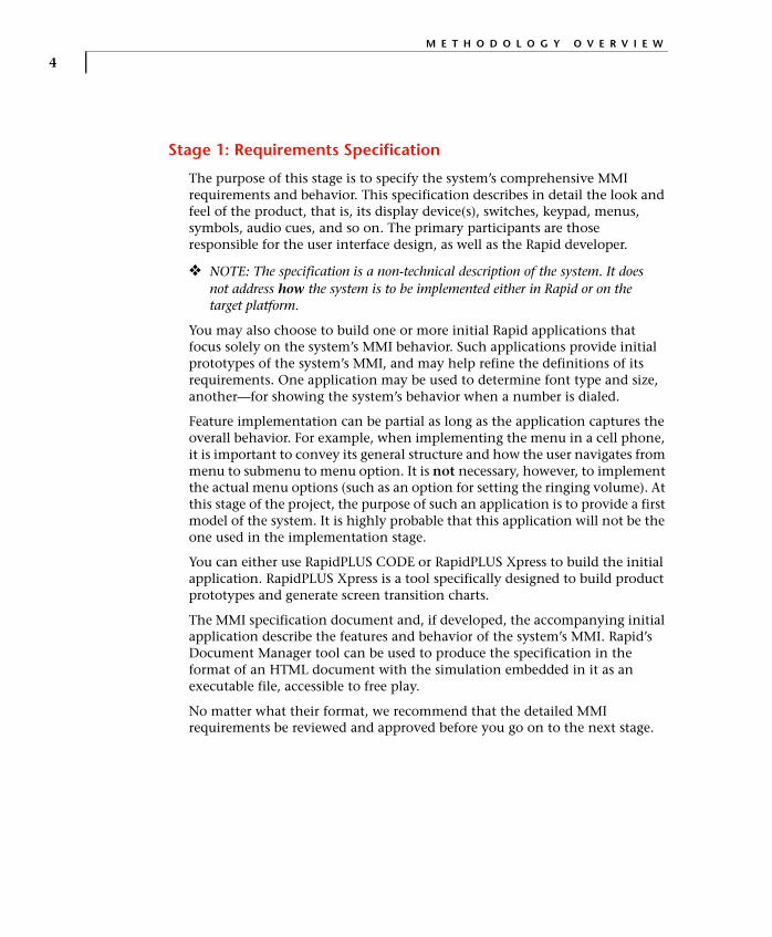
Stage 1: Requirements Specification
The purpose of this stage is to specify the system’s comprehensive MMI requirements and behavior. This specification describes in detail the look and feel of the product, that is, its display device(s), switches, keypad, menus, symbols, audio cues, and so on. The primary participants are those responsible for the user interface design, as well as the Rapid developer.
❖ NOTE: The specification is a non-technical description of the system. It does not address how the system is to be implemented either in Rapid or on the target platform.
You may also choose to build one or more initial Rapid applications that focus solely on the system’s MMI behavior. Such applications provide initial prototypes of the system’s MMI, and may help refine the definitions of its requirements. One application may be used to determine font type and size, another—for showing the system’s behavior when a number is dialed.
Feature implementation can be partial as long as the application captures the overall behavior. For example, when implementing the menu in a cell phone, it is important to convey its general structure and how the user navigates from menu to submenu to menu option. It is not necessary, however, to implement the actual menu options (such as an option for setting the ringing volume). At this stage of the project, the purpose of such an application is to provide a first model of the system. It is highly probable that this application will not be the one used in the implementation stage.
You can either use RapidPLUS CODE or RapidPLUS Xpress to build the initial application. RapidPLUS Xpress is a tool specifically designed to build product prototypes and generate screen transition charts.
The MMI specification document and, if developed, the accompanying initial application describe the features and behavior of the system’s MMI. Rapid’s Document Manager tool can be used to produce the specification in the format of an HTML document with the simulation embedded in it as an executable file, accessible to free play.
No matter what their format, we recommend that the detailed MMI requirements be reviewed and approved before you go on to the next stage.

T H E R A P I D D E V E L O P M E N T M E T H O D O L O G Y
5
Stage 2: Architecture Design
The purpose of this stage is to translate the MMI requirements of the first stage into a Rapid application architecture taking into consideration the target hardware and operating system constraints. The output (either on paper or via a suitable charting tool) is a list of all the application components and a description of their nesting hierarchy. Architecture design involves the following four steps:
1. Identifying project components.
2. Classifying project components.
3. Defining component interface and functionality.
4. Reviewing the design.
Throughout this stage, you should bear in mind testing and debugging needs of the Rapid application. For example, although not specified in any requirements document, it might be useful to include a text display in a network simulator—to show an outgoing telephone number sent to the component by the parent application.
1. Identifying project components
Project components vary in complexity and scope and may be approached from different vantage points. For example, call management, menu, and keypad are all components in a cell phone project. The call management and menu components identify functionalities of variable complexity while the keypad identifies a hardware component.
At this point of the process, you should list all the project components you can identify without attempting to order them in any way. This step is often performed in a brainstorming session.
2. Classifying project components
After identifying all the project components, you need to organize them into a meaningful hierarchy.
Rapid architecture is modular and hierarchical with user objects (*.udo) as its building blocks. User objects are Rapid applications that are used as discrete objects within other Rapid applications. One user object can be nested within another so that a user object may have several nested layers. A project component can consist of one or several user objects with variable nesting in each one.

M E T H O D O L O G Y O V E R V I E W
6
We have found it useful to distinguish three types of application components:
• Application modules
• Services: continuous and on-demand
• Embedded interface
Application modules capture the main functionalities of the MMI and constitute the project’s top-level components. In a cell phone project, the application modules may consist of call management, phone book management, and games.
Continuous and on-demand services (also known as widgets) constitute the middle level of the project. They capture two types of repetitive, self-contained behaviors. Continuous services are ongoing behaviors, such as the measurement of time by a clock. On-demand services are patterns of behavior that are activated when required and deactivated as soon as they are no longer needed, such as a text editor.
You will probably find that some services are nested in more than one application module. For example, an editor service may be common to phone book, Short Message Service, and perhaps games.
❖ NOTE: The distinction between continuous and on-demand services is important only during the implementation phase and can be postponed until that stage.
Embedded interface are the lowest-level components of the project. They commonly represent the hardware parts through which the end user communicates with the system. Typical embedded interface components are a keypad, a display, buttons, and switches. However, software such as a protocol stack or an Internet browser can also be embedded interface components.
3. Defining component functionality and interface
The next step is to clearly describe the functionality to be encapsulated within each user object, as well as the general nature of its interface to the parent application. For example, the keypad component functionality and interface must accurately reflect the actual hardware device’s functionality within the embedded system. The architecture design should also include logic sequence charts that faithfully capture actual embedded system scenarios.
❖ NOTE: At the architecture design stage, it is possible that not all details of the embedded system drivers and external software modules are known or finalized. However, whatever is known about the embedded system on the target platform is important input into the design.

T H E R A P I D D E V E L O P M E N T M E T H O D O L O G Y
7
You also need to describe the parent application’s functionality, which can be summarized as managing the startup process and high-level responsibility for starting and stopping the different application modules.
4. Reviewing the design
Before going on to the implementation stage the application architecture should be verified and approved. The design should be presented to a forum that consists of all the people involved in the project who may have relevant input. The various components and the rationale for each one should be explained.
The purpose of the review is to make sure that the architecture complies with both the MMI and the embedded requirements and that all involved in the project share the same understanding of it. The design review should therefore be attended not only by the embedded and Rapid team leaders but by the individual team members as well. This step is important for establishing a common understanding of the project among all its participants. The review results in approved design documents and possibly a list of open issues.
Stage 3: Implementation
The purpose of this stage is to implement the Rapid application down to the last detail to produce a fully functional simulation that complies with all the previously defined requirements and that is tested in the simulation environment.
As application elements are finalized and implemented, they are integrated into the embedded system environment and tested. In order to enable integration to start as soon as possible, implementation of the components’ interfaces should precede implementation of their internal functionality, and implementation of lower-level components should precede that of higher-level ones. Problems discovered in running the application on the target platform are solved by modifying the implementation and then retesting (in both the simulation and embedded system environments).
As during the design review phase, the Rapid developer leads the way, with input from the system engineer(s) as required.
M E T H O D O L O G Y O V E R V I E W
8
Stage 4: Integration and On-Going Optimization
The purpose of this stage is to write the code that integrates the generated Rapid application with the rest of the embedded system. The output is a generated Rapid application, compiled and linked with the Rapid micro-kernel and tested for the target platform. The main player in this stage is the system programmer, with considerable input from the system engineer and Rapid developer.
Integration takes place in two stages: the code required to activate the Rapid task from the target’s operating system is written first, then the code that enables input and output flow between the Rapid task and other tasks and/or devices. The second stage of integration evolves in parallel with the application implementation. Each component that is integrated is also checked for both response time and memory consumption. Thus, a tight feedback loop of implementation → → → → integration →→→→ unit testing on the target platform →→→→ implementation modifications, is established.
❖ NOTE: Under certain circumstances, it may be legitimate to start integrating the Rapid application on a platform other than the final target platform—in Microsoft® Windows or MS-DOS®, for example.
Stage 5: Final Optimization
The purpose of this stage is to analyze and optimize the performance and memory use of the Rapid task within the target system. The final optimization complements the on-going optimization of individual components, which takes place during the integration stage, by checking how the Rapid task interacts with the embedded system. Other tasks running in the embedded system may produce a need for optimizations in the Rapid task that are not needed when the Rapid task is run by itself.
Stage 6: Acceptance Testing
The purpose of this stage is to release a debugged, generated application that meets all system requirements. The final system testing is based on the same test scenarios used on the simulation application in the simulation environment. The chief participant in this stage is the test engineer.
9
C H A P T E R 2
Requirements SpecificationThe first stage of the Rapid development methodology is to specify the system’s man-machine interface (MMI) requirements and behavior.
Typically, the requirements specification is a document produced by the person responsible for the system’s user interface design, with input from a Rapid developer and the Marketing department. It is not a technical description of how the system will be implemented in Rapid nor on the target platform.
In addition to the document, you can build one or more Rapid simulations to help define and demonstrate the system’s MMI requirements and behavior. Once you have built a simulation, you can use Rapid’s Document Manager tool to produce a document in .html format with the Rapid simulation embedded in it as executable content.
When you use a Rapid simulation to present the system’s MMI, it is important to remember that its purpose is to capture the system’s look and feel. The initial simulation should not implement all of the system’s features down to the final details. For example, if the application is a cell phone that includes a phone book, it is not necessary to implement the ability to store, sort, and retrieve a hundred names and numbers. The prototype should be restricted to the minimal functionality required to demonstrate how the user makes and retrieves a phone book entry.
No matter what format you choose for the requirements specification, it must be reviewed and approved before you go on to the next stage.
R E Q U I R E M E N T S S P E C I F I C A T I O N
10
This chapter describes the MMI requirements and behavior of a system that is used as an example throughout the book. The system is a cell phone named Ref_Design. The Ref_Design application can be obtained from e-SIM.
The purpose of the example is to lead you through the stages of proper Rapid development, not to actually have you build a cell phone based on the requirements specification.
REF_DESIGN REQUIREMENTS SPECIFICATION
Ref_Design is an imaginary cell phone whose MMI is modeled after most cell phones currently on the market. Its MMI features comprise:
• Call management (for incoming and outgoing calls)
• Phone book management
• Menus (for user settings and functions)
• Editing numbers and names
• Language support (two languages: English and French)
• Animation capabilities
• Icon management
• A color graphic display
• A keypad that consists of six function keys (two of which are soft keys) and twelve alphanumeric keys
• A backlight
The requirements are described briefly in this chapter. They are not as detailed as an actual requirements specification document would be.
The following section contains illustrations of the cell-phone’s GUI elements. The illustrations were produced by bringing the Ref_Design application into the Document Manager tool and generating a User Specification document.
R E F _ D E S I G N R E Q U I R E M E N T S S P E C I F I C A T I O N
11
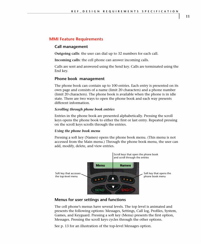
MMI Feature Requirements
Call management
Outgoing calls: the user can dial up to 32 numbers for each call.
Incoming calls: the cell phone can answer incoming calls.
Calls are sent and answered using the Send key. Calls are terminated using the End key.
Phone book management
The phone book can contain up to 100 entries. Each entry is presented on its own page and consists of a name (limit 20 characters) and a phone number (limit 20 characters). The phone book is available when the phone is in idle state. There are two ways to open the phone book and each way presents different information.
Scrolling through phone book entries
Entries in the phone book are presented alphabetically. Pressing the scroll keys opens the phone book to either the first or last entry. Repeated pressing on the scroll keys scrolls through the entries.
Using the phone book menu
Pressing a soft key (Names) opens the phone book menu. (This menu is not accessed from the Main menu.) Through the phone book menu, the user can add, modify, delete, and view entries.
Menus for user settings and functions
The cell phone’s menus have several levels. The top level is animated and presents the following options: Messages, Settings, Call log, Profiles, System, Games, and Keyguard. Pressing a soft key (Menu) presents the first option, Messages. Pressing the scroll keys cycles through the other options.
See p. 13 for an illustration of the top-level Messages option.
Soft key that opens the phone book menu
Soft key that accesses the top-level menu
Scroll keys that open the phone book and scroll through the entries
R E Q U I R E M E N T S S P E C I F I C A T I O N
12
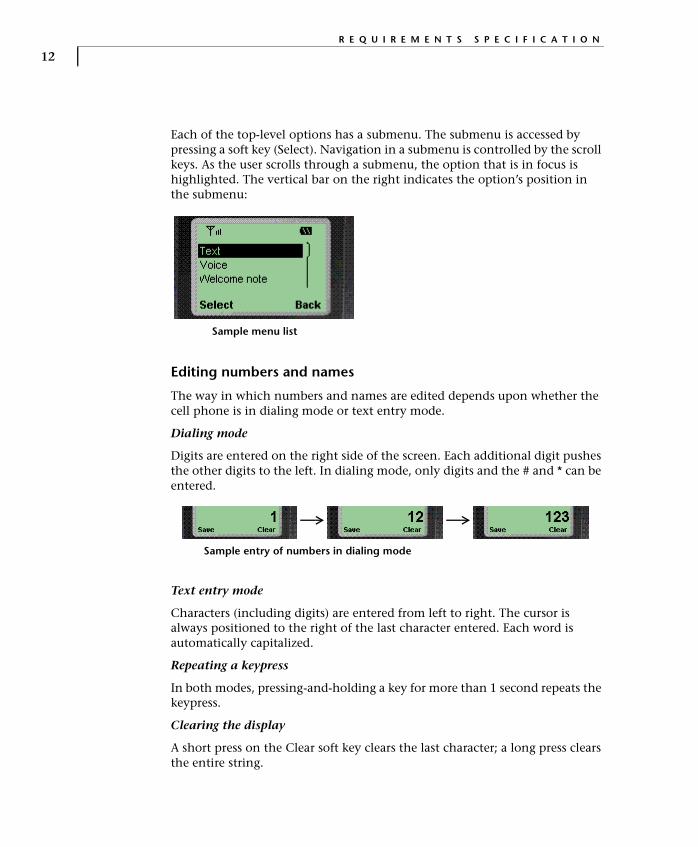
Each of the top-level options has a submenu. The submenu is accessed by pressing a soft key (Select). Navigation in a submenu is controlled by the scroll keys. As the user scrolls through a submenu, the option that is in focus is highlighted. The vertical bar on the right indicates the option’s position in the submenu:
Editing numbers and names
The way in which numbers and names are edited depends upon whether the cell phone is in dialing mode or text entry mode.
Dialing mode
Digits are entered on the right side of the screen. Each additional digit pushes the other digits to the left. In dialing mode, only digits and the # and * can be entered.
Text entry mode
Characters (including digits) are entered from left to right. The cursor is always positioned to the right of the last character entered. Each word is automatically capitalized.
Repeating a keypress
In both modes, pressing-and-holding a key for more than 1 second repeats the keypress.
Clearing the display
A short press on the Clear soft key clears the last character; a long press clears the entire string.
Sample menu list
Sample entry of numbers in dialing mode

R E F _ D E S I G N R E Q U I R E M E N T S S P E C I F I C A T I O N
13
Language support
Two languages are supported: English and French. All text is in English and French; however editing is only supported for English. (If this specification were for a real cell phone, editing in French would also be supported.)
Animation capabilities
Animation on the screen is used for the company logo, for the top-level menu options, and for the powering off message. Suggested animations are shown below:
Company logo
The company logo enters from both sides of the screen and merges in the center.
Top-level menu
All of the seven top-level menu options are animated. Below is a sample animation for the Messages menu.
Powering off
As the cell phone is powered off, the turning hourglass adds interest.
R E Q U I R E M E N T S S P E C I F I C A T I O N
14
Icon Management
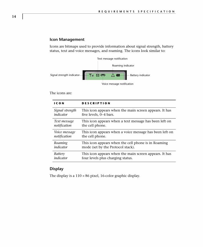
Icons are bitmaps used to provide information about signal strength, battery status, text and voice messages, and roaming. The icons look similar to:
The icons are:
Display
The display is a 110 × 86 pixel, 16-color graphic display.
I C O N D E S C R I P T I O N
Signal strength indicator
This icon appears when the main screen appears. It has five levels, 0−4 bars.
Text message notification
This icon appears when a text message has been left on the cell phone.
Voice message notification
This icon appears when a voice message has been left on the cell phone.
Roaming indicator
This icon appears when the cell phone is in Roaming mode (set by the Protocol stack).
Battery indicator
This icon appears when the main screen appears. It has four levels plus charging status.
Signal strength indicator Battery indicator
Text message notification
Voice message notification
Roaming indicator
R E F _ D E S I G N R E Q U I R E M E N T S S P E C I F I C A T I O N
15
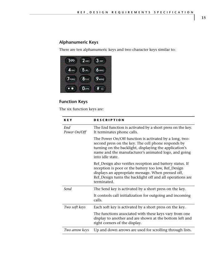
Alphanumeric Keys
There are ten alphanumeric keys and two character keys similar to:
Function Keys
The six function keys are:
K E Y D E S C R I P T I O N
EndPower On/Off
The End function is activated by a short press on the key. It terminates phone calls.
The Power On/Off function is activated by a long, two-second press on the key. The cell phone responds by turning on the backlight, displaying the application’s name and the manufacturer’s animated logo, and going into idle state.
Ref_Design also verifies reception and battery status. If reception is poor or the battery too low, Ref_Design displays an appropriate message. When pressed off, Ref_Design turns the backlight off and all operations are terminated.
Send The Send key is activated by a short press on the key.
It controls call initialization for outgoing and incoming calls.
Two soft keys Each soft key is activated by a short press on the key.
The functions associated with these keys vary from one display to another and are shown at the bottom left and right corners of the display.
Two arrow keys Up and down arrows are used for scrolling through lists.

R E Q U I R E M E N T S S P E C I F I C A T I O N
16
The function keys should look similar to:
Backlight
While the cell phone is turned on, the backlight will automatically go off if no key has been pressed for a period of 10 seconds in order to conserve the battery. The backlight will go on again as soon as any key is pressed.
The six function keys

17
C H A P T E R 3
Architecture DesignThe second stage of the Rapid design methodology is to translate the man-machine interface (MMI) requirements specified in the first stage into a Rapid application architecture.
The result is a high-level design that identifies:
• The Rapid project components: the main application and its user objects.
• Each user object’s functionality, which implements one or more MMI requirements.
• Each user object’s interface, that is, its connection to its parent object and, where known, the specific interface details.
• Code generation considerations, including each user object’s generated type.
• Means of testing in the Rapid simulation the inputs and outputs of interface-only user objects.
• The fundamental functionality of the parent application itself.
The design output, such as a block diagram, can be produced by an outside diagrammming tool. Optionally, you can build the basic components in RapidPLUS CODE , and then generate reports, such as the User Object Interface report and Component Dependencies Tree report, which show the project’s hierarchical structure.

A R C H I T E C T U R E D E S I G N
18
ARCHITECTURE DESIGN METHODOLOGY
The architecture design revolves around the project components: identifying them, defining their functionality, and specifying their interface.
Start the architecture design by listing all system components as derived from the requirements specification. On the basis of the requirements specification, you will probably be able to identify the input/output components (the actual devices through which the user and the system interact) and the main functionality components of the MMI task. However, a Rapid application includes other components that cannot be identified by looking at the requirements specification alone.
The requirements specification is not written from the Rapid point of view and must be analyzed and reworked to fit the Rapid approach. Identifying the components of a Rapid application involves a variety of considerations beyond the requirements specification. These considerations are influenced by the embedded system architecture, by the Rapid process of code generation, by the Rapid method of creating components, and by the ways in which components interact.
Before identifying the components, you should familiarize yourself with the code generation considerations discussed in the next section.
C O D E G E N E R A T I O N C O N S I D E R A T I O N S
19
CODE GENERATION CONSIDERATIONS
The Rapid development tools produce a fully-functioning simulation of an embedded system’s MMI. This simulation runs in the Windows environment only. The Rapid Code Generator transforms this simulation into an executable Rapid application that runs on a real embedded system.
The Rapid simulation includes representations of actual objects such as keypads, switches, and protocol stacks as well as logic that controls their behavior. When code is generated, these objects and their logic become redundant since they already exist in the embedded system. The only thing required of these objects is an ability to communicate with the embedded system on the one hand and the Rapid task on the other.
We therefore want the Code Generator to process the interface, but to ignore the internal logic. The Code Generator has such a processing option, but it can be applied only to a stand-alone component; the Code Generator cannot apply different processing types to sections of logic within the same file. Whenever such specialized generation is required, a separate component known as a user object must be created.
A user object is a Rapid application that has been built with an interface that enables it to be used as an encapsulated object inside other Rapid applications. When user objects undergo code generation, code can be generated only for their interface so they can form the link between the embedded system and the Rapid application.
Types of Code Generation
Rapid provides four types of code generation for each user object:
• Full object
• Interface only
• Data container
• Empty task
User objects generated as full objects (*.udo)
By default, user objects are generated in their entirety, as actual objects. This means that code is generated for their nongraphic objects, internal logic, and interface to the parent application. This method of code generation applies to user objects that were created in order to split the application into smaller, easier-to-manage components.

A R C H I T E C T U R E D E S I G N
20
User objects generated as interface only
Various components that are used during the development phase to simulate the embedded side of the project are not needed in the generated code; for example, simulated input and output devices (such as buttons and displays), communication protocols, low-level and other software modules, drivers—all already exist on the target platform.
These objects are incorporated in user objects that are defined for code generation as “interface only.” This method of generation ensures that code is generated only for the user object’s interface, which is generated as an API. Neither the objects nor the internal logic of the user object are generated.
When the user object is integrated into the embedded system, the place of its non-generated objects and internal logic is filled by the corresponding embedded system module.
User objects generated as data containers
This method of generation is a specialized extension of “interface only” generation. It applies only to user objects with a message interface, where the message is used solely for storing data that can be shared by different components. Since the message serves only as a data container, its built-in, send/receive mechanism is redundant and not generated.
For more information, read the section “Using Messages as Data Containers” in Chapter 16: “User Objects with Messages” of the User Manual Supplement.
User objects generated as empty tasks
Generated Rapid code runs in a single task. When the Rapid application includes a graphic display object, it is an integral part of the Rapid task. However, constraints of the embedded system may require a separate task for the graphic operations. The Code Generator is capable of splitting the graphic

C O D E G E N E R A T I O N C O N S I D E R A T I O N S
21
display from the main Rapid task, but can do so only when the graphic display object is in a separate user object.
Whenever the embedded system requires a separate task for graphic operations, the graphic display must be handled by a discrete user object. This user object must be flagged as an empty task for code generation.
For more information, read Chapter 7: “Splitting the Rapid and Graphic Tasks” in the Generating Code manual.
Interface of User Objects
The previous section showed how the code generation options offered by Rapid impact the architecture of the application. A Rapid application destined for code generation will usually combine several user objects. These user objects must be given means to communicate with their parent application (i.e., the application that contains the user object). Rapid provides various elements you can add to a user object to enable it to interact with its parent application. These elements make up the user object’s interface, and they consist of:
• Exported properties
• Exported events
• Messages
• Exported functions
User object selected for generation as a separate task

A R C H I T E C T U R E D E S I G N
22
Exported properties, exported events, and messages are created in the User Object Properties dialog box. Functions are created in the Function Editor and are also visible in the User Object Properties dialog box.
Exported properties
When a property is added to a user object, it is listed in the Logic Palette among the user object’s properties, and its value can be read or assigned by the user object’s parent application. Exported properties thus enable bidirectional communication between the user object and its parent application; the user object can pass data to the parent application and vice versa.
Properties can be of the following types: string, integer, number, and constant set. In the Rapid simulation you can also use point properties. However, this property type is not supported for code generation.
Exported events
Like other objects, user objects can generate events. These events can be used in the logic of the user object’s parent application. An exported event enables communication from the user object to the parent application. The user
C O D E G E N E R A T I O N C O N S I D E R A T I O N S
23
object notifies the parent application that the event has occurred, and the parent application can then respond to this information.
For an event to occur, it must be triggered within the user object. You should therefore ensure that each exported event is triggered somewhere in the user object’s logic.
Exported events are listed in the Logic Palette in the Property column.
Messages
A message is data that is transferred between objects in a defined format. It enables bidirectional communication between a user object and its parent application. A message is made up of structures whose basic members, or fields, are: string, integer, number, and array. Once a structure has been defined, it can be incorporated as a nested member in another structure, thereby creating a multilevel structure. Messages can be used to send complex data from the user object to the parent application and vice versa.
Messages are listed in the Logic Palette in the Property column.
Exported functions
A user function is a block of Rapid logic that can be invoked as a single function within an activity, action, or condition. Exported functions enable communication from the parent application to the user object. When a function of a user object is exported, it is listed among the user object’s functions in the Logic Palette and is available to the user object’s parent application. The parent application can use exported functions to directly influence the behavior of objects within the user object.
A user function can have one or more arguments. Defining all, or some, of a user function’s objects as arguments gives the function greater flexibility. The following objects can be used as arguments in functions:
• Strings
• Integers
• Numbers
• Arrays
• User objects
• Graphic displays and fonts

A R C H I T E C T U R E D E S I G N
24
Implementing Interface in Generated Code
The properties, events, messages, and functions that make up the interface of user objects are generated as macros and empty functions. These can easily be used to integrate with the embedded operating system and other embedded software. The embedded system programmer implements the interface layer by filling in the empty generated functions and calling the generated macros.
The interface layer ensures that:
• Output from the Rapid task is in the format that the embedded system can process.
• Input to the Rapid task is translated into a format that Rapid can process.
For example, the output from the Rapid task may be through functions of user objects generated as interfaces only. Rapid generates exported functions as empty functions. In the user object’s generated source code file, the embedded system programmer writes C code that implements these functions in terms that are meaningful to the embedded system.
The interface layer also manages system input into the Rapid task. This part of the interface may be written in any file or files, as long as they are compiled together with the generated source code files. Rapid provides an API whose functions can be called from the interface layer.
/******************************//***** Exported functions *****//******************************/void LAMP_R11555_lampOn ( LAMP* udo)
{/******** RapidUserCode BEGIN LAMP_R11555_lampOn ********/
gotoxy(5,22);printf("Lamp is ON ");
/******** RapidUserCode END LAMP_R11555_lampOn ********/
User code in exported function of user object generated as "interface only"

C O D E G E N E R A T I O N C O N S I D E R A T I O N S
25
Code Generation Process
The code generation process can be summarized as follows:
1. The Code Generator translates the Rapid application and each of its user objects into C source code files.
2. The embedded system programmer writes a thin interface layer, ensuring that the functions of user objects generated as interface only are implemented in terms meaningful to the embedded system, and system messages are translated into the data structures understood by Rapid. Calls to Rapid-supplied functions and macros initiate and start the Rapid task, pass system messages, and update the Rapid timer objects.
3. Using the embedded system’s compiler and linker, the generated source code files and the interface code are compiled and then linked with the precompiled microkernel supplied by e-SIM. The result is an executable Rapid application, or Rapid task, which is in turn linked with the rest of the embedded system software to create an executable image for downloading to the target platform.
int processKeyDown(int pressedKey){
switch(pressedKey){
case KEY_1:R3668_KEYPAD_set_keyCode(1);R2335_KEYPAD_pressed();break;
case KEY_2:R3668_KEYPAD_set_keyCode(2);R2335_KEYPAD_pressed();break;
default:return 0;
}}
User API code calling generated macros following a key press
A R C H I T E C T U R E D E S I G N
26
IDENTIFYING COMPONENTS
Rapid applications have a modular, hierarchical structure. Their components are user objects: Rapid applications that can be used as encapsulated units within other Rapid applications. Each component implements its own particular functionality, with upper-level components incorporating lower-level ones.
When you create the component list for a Rapid application, aim to achieve:
• Easy future maintenance and support. Creating a functionality as a separate user object insulates the rest of the application from the effect of future changes in the user object.
• Efficient resource usage and performance.
• Easy and fast development.
There is a trade-off between ease of development and maintenance on the one hand and economical resource usage and high performance on the other. It is a common mistake during the design stage to impose on Rapid a C-oriented approach, which sees components in terms of source files and builds a user object for each cluster of functions: power up, power down, incoming call, outgoing call, etc. On the other extreme, it is possible to build any Rapid application from one main application and a single embedded interface user object. Such an approach may be applied to applications with a small amount of functionality and very tight memory limitations, but will make it hard to use group development and maintain large applications.
The Rapid approach is more discriminating. Some function clusters may be handled within a single, more inclusive component, for example, incoming and outgoing calls may both be handled within the call management component. Other function clusters, such as power on and power off, which occur only once throughout the application, may be implemented within the main application. The key considerations in these decisions are the price—in resource and performance—of a user object versus the size and complexity of the functionality to be implemented.
The components that make up Rapid applications fall into three categories:
• Application modules
• Services: continuous and on-demand
• Embedded interface components
The relationship among the three component types is hierarchical. The application modules constitute the top level of the hierarchy while the embedded interface components constitute its bottom level.

I D E N T I F Y I N G C O M P O N E N T S
27
Top-level and bottom-level components are basically givens. Top-level components reflect the main functionalities of the MMI task. Bottom-level components are dictated by the embedded system. Each bottom-level component represents an input or output device (hardware or software) that exists in the embedded system. The creation of mid-level components is motivated by project management considerations such as software reusability, maintenance, and group development, or preferences for streamlining and encapsulation.
The following sections discuss each of the component categories and provide examples from the Ref_Design application. The section on services provides various criteria for creating service user objects and establishes a distinction between two types of service user objects.
How many components to use?
The many advantages offered by user objects do not come without a price tag. In the generated code, each user object that is added to the project, regardless of its content, carries a ROM overhead of 0.4KB. In a project with limited memory resources, in spite of the many advantages of user objects, you must strike a careful balance between the number of user objects and the available memory. When the logic is small and used in a single component, it may be preferable to use a concurrent mode or an internal function instead of a separate user object.
Embedded Interface Components
Any part of the embedded system, hardware or software, that communicates with the MMI task through input or output must be represented by an embedded interface user object. Common examples of embedded interface components are a keypad user object, which represents the embedded system’s keypad, and a protocol stack user object, which represents the embedded system’s communication with the network.
Because embedded interface user objects represent components that are part of the embedded system, the internal logic of these user objects is irrelevant for code generation. They must however communicate with the embedded system in the manner that fits its communication abilities. This communication is defined in the user object’s interface, which is the only part of its logic for which code will be generated.
TIP: Embedded interface user objects must be generated as “interface only”.

A R C H I T E C T U R E D E S I G N
28
In designing the embedded interface components, we aim to achieve an easy mapping from the existing external C code to Rapid. For example, if the existing C code is based on structures, it makes sense to define messages as the component’s interface. The main considerations for selecting the interface type are: minimizing the amount of required integration work, reducing memory consumption, and simplifying future changes and maintenance.
Embedded interface components are the lowest level of the Rapid component hierarchy, and so do not contain other components.
Example
In designing the embedded interface keypad user object in the Ref_Design application, we first examined what kind of input is available from the keypad driver. We found that this input is very basic; when a key is pressed, there is a system message or callback function that provides information about the event (key in, key out) and the key code. The easiest way to map this input to Rapid is through two events—key in and key out—and an integer property that contains the code of the pressed key.
The Ref_design application contains the following embedded interface user objects:
• EABDATA.UDO represents the memory area where the phone book information (names and phone numbers) is stored. Communication between the parent application and the embedded component is bidirectional. The embedded component provides its parent application with the current content of the phone book memory and updates the content when it has been changed in the parent application.
• EMB_BATT.UDO represents the phone’s battery. It powers off the phone when the battery power level is below five percent. It also communicates to its parent application information that affects the display of the battery icon and popup messages.
• EMB_BKLT.UDO represents the phone’s backlight. The parent application notifies the embedded system when to turn the backlight on and off.
• EMB_NET.UDO represents the system’s connection with the communications network. Communication between its parent application and this embedded component is bidirectional. The component informs its parent application about incoming calls and new messages. It also communicates to the Rapid application information that affects the display of the RSSI level icon and the roaming icon. The parent application notifies the user object about outgoing calls so it can establish the connection with the communications network.
I D E N T I F Y I N G C O M P O N E N T S
29
• EMB_KPD.UDO represents the phone’s keypad. It informs its parent application of key manipulations.
• TEXTRES.UDO represents the memory area where all the texts used in the cell phone’s interface (e.g., menu options, soft key labels) in both English and French are stored. The component provides Rapid with the content of the required text literals.
Service Components
Services (also known as widgets) are components that provide specialized functionality to higher-level components. They implement behaviors that can be more efficiently handled as separate components either because they are common to several application modules, or because they create a flexible buffer between embedded interface components and application modules.
Service components simplify system building and maintenance. They can contain embedded interface components and/or other service components. Their creation is in many cases optional and is motivated by the interplay of optimization and design considerations.
Service components are divided into two types: continuous services and on-demand services. See pp. 32–36 for information about both types of service components.
Reasons for creating service components
The following sections present reasons for creating service components.
Breaking down application modules
Breaking down application modules into smaller components makes them easier to conceptualize and implement. The more complex the application, the greater the need for breaking it down into smaller units. A smaller unit will consist of a self-contained behavior that governs a certain aspect of functionality.
Example
In the Ref_Design application, there are services to handle the animations accompanying the main menu options, the display of text labels, editing, popup messages, and so on. In each of these examples, the service user object replaces a block of logic in the application module.
The following illustration shows the components contained in the menu management application module. Of these components, ANIMATOR—the component responsible for displaying the animations of the main menu

A R C H I T E C T U R E D E S I G N
30
options—exemplifies a component created in order to break down a larger component into smaller ones.
❖ NOTE: Although service_GDO is an integral Rapid object and not a user object, it is included in the design scheme because it serves as the main output object for the system.
Reusability
Often, a behavior is repeated in various application modules. For example, in a cell phone application, editing is required when dialing a number, when making an entry in the phone book, and when personalizing the welcome message. We may also know that when a games module is implemented, it too will require editing services.
The editing behavior in all these situations is essentially the same. It makes more sense to create an editor user object that can be activated whenever editing services are needed rather than include editing logic in each of the upper-level components. Reusability of objects and their logic within or across projects is a strong argument for creating them as separate components.
Example
Services can also be used as building blocks for other services. The following illustration shows that in the Ref_Design application, there is an editor service that uses three other services: edit box, label, and keypad.
MENUHMI
SETS_SRVEDITOR
KEYPADservice_GDO
TEXTRES MENUMNGANIMATOR
LABEL
Structure of MENUHMI.UDO, the menu management application module
I D E N T I F Y I N G C O M P O N E N T S
31
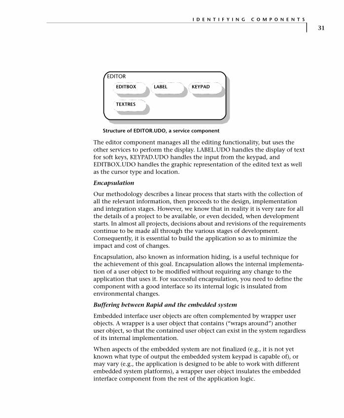
The editor component manages all the editing functionality, but uses the other services to perform the display. LABEL.UDO handles the display of text for soft keys, KEYPAD.UDO handles the input from the keypad, and EDITBOX.UDO handles the graphic representation of the edited text as well as the cursor type and location.
Encapsulation
Our methodology describes a linear process that starts with the collection of all the relevant information, then proceeds to the design, implementation and integration stages. However, we know that in reality it is very rare for all the details of a project to be available, or even decided, when development starts. In almost all projects, decisions about and revisions of the requirements continue to be made all through the various stages of development. Consequently, it is essential to build the application so as to minimize the impact and cost of changes.
Encapsulation, also known as information hiding, is a useful technique for the achievement of this goal. Encapsulation allows the internal implementa-tion of a user object to be modified without requiring any change to the application that uses it. For successful encapsulation, you need to define the component with a good interface so its internal logic is insulated from environmental changes.
Buffering between Rapid and the embedded system
Embedded interface user objects are often complemented by wrapper user objects. A wrapper is a user object that contains (“wraps around”) another user object, so that the contained user object can exist in the system regardless of its internal implementation.
When aspects of the embedded system are not finalized (e.g., it is not yet known what type of output the embedded system keypad is capable of), or may vary (e.g., the application is designed to be able to work with different embedded system platforms), a wrapper user object insulates the embedded interface component from the rest of the application logic.
EDITOR
LABEL
TEXTRES
KEYPADEDITBOX
Structure of EDITOR.UDO, a service component

A R C H I T E C T U R E D E S I G N
32
The wrapper creates a buffer that protects the Rapid application from the effects of changes in the embedded interface component. When such changes occur, all the necessary modifications are made only in the wrapper component. The use of wrapper components enhances the flexibility of the Rapid application and greatly simplifies its adaptation to different embedded system environments.
Extended functionality
Wrapper user objects can also be used to extend the functionality of the wrapped user object by providing a “translation” mechanism. For example, if the embedded system keypad is capable only of key in/key out events, the wrapper keypad user object can add the logic that transforms these events to short, long, and repeated key presses. In the Ref_Design application this is exactly what the keypad user object does; it wraps around the embedded interface component, EMB_KPD.UDO.
Continuous vs. On-Demand Services
Services are divided into two types: continuous services whose functionality is available whenever the application is running and on-demand services that must be activated before their functionality can be used. The differences between the two service types affect their choice of interface as well as their implementation and are discussed in detail in the following sections.
Continuous services
Continuous services become usable as soon as the Rapid application is started and remain so as long as the Rapid application is running. The only exception to this rule is when the need to simulate a “power off” state requires introduction of an idle mode for the service. Otherwise, a continuous service is active and accessible all the time. Because they are uninterruptedly active, continuous services can hold data for the application. The information that they have about their status is meaningful to, and can be used by, other components of the application.
Continuous services are used for functionalities that must be always operative and available.
Example
The following user objects are examples of continuous service components from the Ref_Design application:
• ABDATA.UDO is the wrapper of the embedded phone book component (EABDATA.UDO), which hold the phone book data. ABDATA.UDO has a
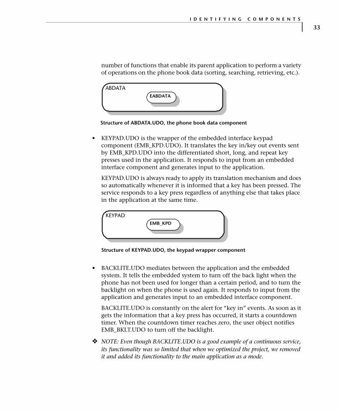
I D E N T I F Y I N G C O M P O N E N T S
33
number of functions that enable its parent application to perform a variety of operations on the phone book data (sorting, searching, retrieving, etc.).
• KEYPAD.UDO is the wrapper of the embedded interface keypad component (EMB_KPD.UDO). It translates the key in/key out events sent by EMB_KPD.UDO into the differentiated short, long, and repeat key presses used in the application. It responds to input from an embedded interface component and generates input to the application.
KEYPAD.UDO is always ready to apply its translation mechanism and does so automatically whenever it is informed that a key has been pressed. The service responds to a key press regardless of anything else that takes place in the application at the same time.
• BACKLITE.UDO mediates between the application and the embedded system. It tells the embedded system to turn off the back light when the phone has not been used for longer than a certain period, and to turn the backlight on when the phone is used again. It responds to input from the application and generates input to an embedded interface component.
BACKLITE.UDO is constantly on the alert for “key in” events. As soon as it gets the information that a key press has occurred, it starts a countdown timer. When the countdown timer reaches zero, the user object notifies EMB_BKLT.UDO to turn off the backlight.
❖ NOTE: Even though BACKLITE.UDO is a good example of a continuous service, its functionality was so limited that when we optimized the project, we removed it and added its functionality to the main application as a mode.
ABDATAEABDATA
Structure of ABDATA.UDO, the phone book data component
KEYPADEMB_KPD
Structure of KEYPAD.UDO, the keypad wrapper component

A R C H I T E C T U R E D E S I G N
34
• ICONS.UDO receives information from embedded interface components (battery and network) and presents the information as icons on the phone’s display.
ICONS.UDO is constantly on the watch for relevant information; as soon as such information is received, it is automatically processed, and the corresponding icon is displayed.
• SETS_SRV.UDO mediates the flow of settings data (display language, welcome message, ring sound, etc.) between the application and the memory area that stores this data.
• CALL_SRV.UDO mediates call management between the application and the network. For incoming calls, it responds to input from the embedded network component and generates input to the application. For outgoing calls, the direction is reversed.
CALL_SRV.UDO holds the status of the current call information for the application. It waits for both incoming and outgoing calls. As soon as it detects the presence of either one, it automatically applies the appropriate processing.
On-Demand Services
In contrast to continuous services that are constantly on the alert for agents that affect their behavior, on-demand services are “asleep” unless deliberately awakened. When awake, on-demand services respond to the presence of appropriate agents just like continuous services. However, on-demand services return to their dormant state as soon as they have completed their specific task or when they are given a stop command. As soon as they return to their dormant state, on-demand services lose all their data and all memory of the
ICONS
EMB_BAT EMB_NET service_GDO
Structure of ICONS.UDO, the service component that displays icons
CALL_SRV
SETS_SRVTEXTRES EMB_NET
Structure of CALL_SRV.UDO, the call notification component

I D E N T I F Y I N G C O M P O N E N T S
35
processing that occurred while they were active. When next activated, they must be re-supplied with data.
On-demand services are controlled by the user objects that require their functionality. An on-demand service is called when it is needed and dismissed as soon as it is no longer in use. When an on-demand service is dormant, it does not respond to any events in the application.
On-demand services are used for functionalities that take place only under a particular set of circumstances. For example, in a word processing application the scroll bar is displayed only when the content exceeds the visible space. Therefore, this functionality is best handled as an on-demand service.
We want the service to become and remain active only under a specific set of circumstances. At the same time we want to reserve the option of deliberately deactivating the service (for example, if the user can choose not to display the scroll bar). The scroll bar service becomes active only when it is required, performs its service, then goes back to a dormant state when no longer needed or when stopped.
Many components may use the same on-demand service; however, at any given time the on-demand service can serve only a single component. Although an on-demand service is always governed by the same logic, it uses fresh data every time it is activated.
Example
The Ref_Design application includes a selection bar that is used in lists of menu options. The size of the selection indicator varies by the total of available selections: it is largest when only two selections are available and becomes proportionately smaller as the list of selections grows.
The selection bar service is activated each time a menu with options is selected, is then supplied with the relevant data that includes the number of options, calculates the size of the selection point, draws the bar on the display, then returns to its dormant state retaining no memory of the data it used (which is anyway not going to be relevant then). The same process is repeated when another menu is selected.
The following user objects are examples of on-demand service components from the Ref_Design application:
• ANIMATOR.UDO displays the animations of the initial display and the main menu options. It is activated by two modules: the module that manages the phone’s initial display and the module that manages menus.
A R C H I T E C T U R E D E S I G N
36
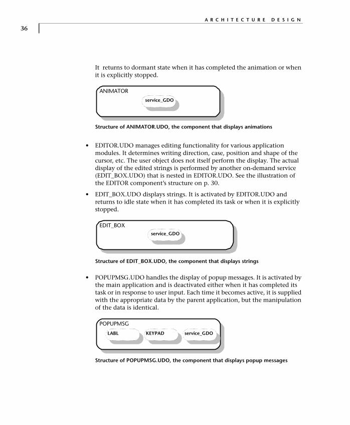
It returns to dormant state when it has completed the animation or when it is explicitly stopped.
• EDITOR.UDO manages editing functionality for various application modules. It determines writing direction, case, position and shape of the cursor, etc. The user object does not itself perform the display. The actual display of the edited strings is performed by another on-demand service (EDIT_BOX.UDO) that is nested in EDITOR.UDO. See the illustration of the EDITOR component’s structure on p. 30.
• EDIT_BOX.UDO displays strings. It is activated by EDITOR.UDO and returns to idle state when it has completed its task or when it is explicitly stopped.
• POPUPMSG.UDO handles the display of popup messages. It is activated by the main application and is deactivated either when it has completed its task or in response to user input. Each time it becomes active, it is supplied with the appropriate data by the parent application, but the manipulation of the data is identical.
ANIMATOR
service_GDO
Structure of ANIMATOR.UDO, the component that displays animations
EDIT_BOXservice_GDO
Structure of EDIT_BOX.UDO, the component that displays strings
POPUPMSG
KEYPAD service_GDOLABL
Structure of POPUPMSG.UDO, the component that displays popup messages

I D E N T I F Y I N G C O M P O N E N T S
37
Application Modules
Application modules constitute the top level of the component hierarchy. They are an organizational tool and usually correspond to the main function-alities the application offers to its end user. Decisions on the number and scope of application modules take into consideration the following factors:
• Intuitive division of functionality.
• Development ease and speed, including team development.
• Size and complexity of the involved logic.
Example
In the Ref_Design application, the application modules reflect the various functionalities the cell phone application offers: phone book management, call management, and menu management. The following illustrations present the structures of the call management and menu management application modules. Both application modules contain a variety of lower-level and service components.
CALLHMI
CALL_SRV
KEYPAD service_GDOTEXTRES
LABELABDATA
Structure of CALLHMI.UDO, the call management application module
ABDATAHMI
CALL_SRVEDITOR
service_GDO
TEXTRES MENUMNG
KEYPAD
ABDATA
LABEL
Structure of ABDATAHMI.UDO, the phone book management application module

A R C H I T E C T U R E D E S I G N
38
Ref_Design has one additional application module that handles the phone’s startup activities, i.e., everything that happens in the phone (display of application name, animated display of manufacturer’s logo, and display of initial menu) from the moment it is turned on until it is ready for operation.
In a cell phone application that includes games and handles SMS, these functionailities will each constitute an application module. The main purpose of the division into application modules is to simplify the conceptualization and handling of the application.
Using Holders to Share Components
When a component, such as an editor user object or a keypad user object, is used in other components within a single project, certain adjustments must be made. On the one hand, in order to facilitate maintenance and conserve resources, we would want to have a single instance of the user object in the application. Moreover, some user objects—particularly those that represent embedded system hardware like an embedded keypad user object—cannot have more than a single instance in the application. On the other hand, in order to be truly self-sufficient and stand-alone, each component that uses the user object would require its own instance.
The design solution lies in the use of holders. Instead of duplicating the shared user object in each application module that uses it, you can define a holder for the user object type in each of the relevant modules. All the holders for the same user object type point to the same user object, thus making it possible for any number of components to share a single user object. Each holder acquires the interface elements of the user object it points to, allowing the parent application to interact with the holder as if it were the user object itself.
To make it possible for the holder to act as a proxy for a user object, the holder must be initialized. Initialization of a holder provides it with the pointer link to its held user object. Normally the main application initializes all holders at application start. This solution is used in the following illustration.

I D E N T I F Y I N G C O M P O N E N T S
39
Using a holder instead of multiple instances of a user object not only simplifies the logic of the application, but economizes memory resources. Memory is allocated for a single instance.
Moreover, the user object defined as the holder’s type does not need to be included in the application. Rapid provides a holder function that makes it possible for the holder to generate its user object during runtime. As a result, RAM for the user object is allocated dynamically, only when the user object is in use.
In applications with very limited memory resources, you may decide to create a separate user object solely in order to use it in a dynamically allocated holder and so achieve better resource management. The same considerations may lead you to use a holder for a user object even when the user object is needed only in a single application module.
Example of holder objects used to hold user objects
Init: <Keypad>
Keypad
Main Application
Menu Component
GDO Holder Keypad Holder
Init: <GDO>
Graphic Display Object
Init: <Keypad>
Keypad
Main Application
Menu Component
GDO Holder Keypad Holder
Init: <GDO>
Graphic Display Object Keypad
Main Application
Menu Component
GDO Holder Keypad Holder
Init: <GDO>
Graphic Display Object
A R C H I T E C T U R E D E S I G N
40
Creating the Main Application
When all the application components have been identified and organized, they must be brought together in the main application. The main application contains all the application modules and all the shared service and embedded interface components. The only service and embedded interface components that are not directly included in the main application are single-instance components.
The main application is responsible for the proper flow of the allocation. It populates or clears holders and sets processing priorities.
Example
In the Ref_Design application, there are two single-instance components, both of them of the embedded interface type: the embedded interface keypad component (EMB_KPD.UDO) and the embedded interface component that simulates the phonebook memory (EABDATA.UDO). Both these components are used by a single service each (KEYPAD.UDO and ABDATA.UDO, respectively). The services in which they are nested are, however, shared by a number of different components.
COMPONENT FUNCTIONALITY
The functionality of user objects is defined in the requirements specification. However, although the sum total of all the components should fulfill all the requirements specified by the manufacturer, the components identified in the architecture do not always have a 1:1 relationship with the components described in the specification. In most cases, it will be necessary to go through the specification carefully and cull the functionality of each user object.
In some cases this will mean dividing a description of functionality among several components. An example would be dividing the menu navigation functionality among the menu application module, the menu manager service, the list service, and others. In other cases, several functionality descriptions might belong to a single component. Thus, while in a cell phone application, as in the case of Ref_Design, a single editor component might provide both dialing and phone book editing; in the requirements specification the two editing functionalities are more likely to be described separately.

C O M P O N E N T I N T E R F A C E
41
COMPONENT INTERFACE
The interface of user objects is their means of communicating both with the embedded system and with other user objects. The various interface options were presented on pp. 21–25. Unless the embedded system imposes constraints on the type of interface, there is a choice between the various interface options. For example, communication can be achieved by using exported events and properties as well as by using messages.
Although the differences among interface types have no significant effect on the Rapid simulation, they can profoundly affect the generated code because of the way the Code Generator handles each type. The choice of interface affects both the consumption of resources and the amount of work required of the system integrator.
The following sections present the code generation implications of the user interface types to assist you in making the choices.
Interface with the Embedded System
User objects that communicate with the embedded system are of the embedded interface type, and therefore, are always generated as “interface only.” This means that their internal logic is removed during code generation. When interface elements are manipulated through the object’s internal logic, some manual adaptation will be required in the generated code.
Exported properties
Properties can be used for communication from the parent application to the embedded system and back. The Code Generator produces two macros and a “property changed” function for each property. The macros can set and get the property’s value, and must be implemented by the system integrator.
When a property has been changed in the embedded system (e.g., the set macro has been used), the Rapid parent application is automatically notified. When the property has been changed in the Rapid application, the embedded system is notified through the “property changed” function. This function must also be implemented by the system integrator.
Properties are limited to simple data types: integer, string, and number. They cannot be used to implement arrays or data stores.
Example
In the Ref_Design application, we used an exported property to implement the embedded interface keypad component (EMB_KPD). This component has

A R C H I T E C T U R E D E S I G N
42
an integer-type property named code, which gets a value from the embedded system and transmits it to the Rapid application.
Although exported properties are available for bidirectional communication, in EMB_KPD we used the property in one direction only, from EMB_KPD to its parent application.
Exported events
Events can be used for communication from the embedded system to the Rapid parent application. The Code Generator creates them as macros that require no RAM.
TIP: Events are the simplest and most economical means of communication between the embedded system and the Rapid application, and should be the preferred interface whenever possible.
Example
The interface of the EMB_KPD component shown above includes two events: keyIn_Ev and keyOut_Ev. The first is generated when a key is pressed. The second is generated when the pressed key is released. Together with the code exported property, this interface makes it possible for EMB_KPD to notify its parent application about which key the user has pressed.
Instead of the exported property and event interface we chose for EMB_KPD, we could have used a message interface. In most cases the type of interface is dictated by the embedded system. When there is a choice, or when the embedded system environment has not been finalized, the more efficient interface should be preferred. In the case of EMB_KPD, a message interface would have required considerably more RAM (see the following section). The additional RAM consumption is particularly unjustifiable in view of the small amount of data (one integer) involved.
Messages
Messages enable sending “data-combined-with-an-event” from the embedded system component to the parent application and vice versa. The data of a
code (integer)
keyOut_Ev
keyIn_EvEMB_KPD Events:
Properties:
Interface of EMB_KPD.UDO, the embedded keypad component

C O M P O N E N T I N T E R F A C E
43
message is organized in structures that can consist of fields of strings, integers, numbers, arrays, and other structures. A structure must be part of a union. A single union may contain many structures.
The RAM resources required by messages are determined at the union level by the largest structure member. In other words, a union takes up the same amount of RAM regardless of the number of structures it contains. Adding more message structures to an existing union does not increase the required RAM. Therefore, when a union already exists, as many messages as possible should be added to it. However, when only a small amount of data needs to be transferred, it is more economical to use a property instead of a message.
Example
A pointer type message interface is used in the interface of the embedded phone book component EABDATA.UDO.
The advantage of this type of interface lies in avoiding data duplication. Because the phone book data is already stored in the memory of the embedded system, instead of copying the data into Rapid, we use a pointer to reference the respective memory area.
Data containers
When sending the message is not required, a message interface without the send/receive mechanism can be used as an economical data container. When the proper code generation option is used (see “User objects generated as data containers” on p. 20), the Code Generator leaves out the activate, send, and deactivate functions, thereby reducing ROM usage. The data in the user object’s message interface can be accessed by both the parent application and the embedded system through an exported function of another interface-only user object that uses the data container object as a parameter.
Union EmbData_uStructure EmbData_str
Entry_str Array ArrayInteger RecNumString F1String F2
Integer Error
getEMBdata
embReady_evEABDATA Events:
Messages:
Functions:
Interface of EABDATA.UDO, the embedded phonebook component

A R C H I T E C T U R E D E S I G N
44
Example
In the Ref_Design application, we implemented this type of interface in the settings component (SETS_SRV), which holds a variety of setting parameters such as last selected language, welcome greeting, and ringer volume.
Replacement of a standard message interface by a ROM-saving data container was made possible by the fact that the message’s send/receive mechanism is not used in the application. This component is held as a pure data object by the other components that require the settings data.
Interface Among Full User Objects
User objects that do not communicate with the embedded system are usually generated as full objects (*.udo). This means that all their internal objects and data is generated, and no additional user code is required. However, the choice of interface type may affect resource usage and performance.
Exported properties
Properties can be used for communication between a child user object and its parent application. A property change in either one of them is noted in Rapid’s trigger queue. The state machine then checks all the application logic dependent on this property-change trigger, and performs all the logic that applies to the active modes in both the parent application and the child user objects.
In order to make use of the property change, the Rapid developer must build a condition-only transition that is based on it. We recommend avoiding the use of condition-only transitions in internal transitions because when such conditions remain true for an extended time, they burden the system.
Properties are limited to simple data types: integer, string, and number. They cannot be used to implement arrays or data stores.
Interface of SETS_SRV.UDO, the settings component
Union userStructure data
Integer RingerVolumeInteger backlightString greetingString providerInteger language
SETS_SRV Messages:
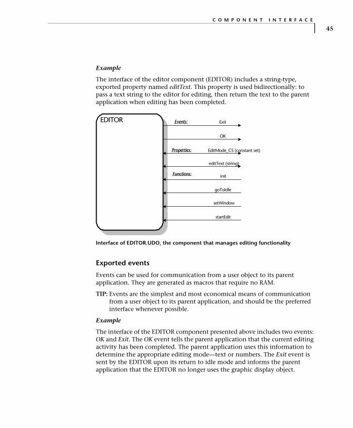
C O M P O N E N T I N T E R F A C E
45
Example
The interface of the editor component (EDITOR) includes a string-type, exported property named editText. This property is used bidirectionally: to pass a text string to the editor for editing, then return the text to the parent application when editing has been completed.
Exported events
Events can be used for communication from a user object to its parent application. They are generated as macros that require no RAM.
TIP: Events are the simplest and most economical means of communication from a user object to its parent application, and should be the preferred interface whenever possible.
Example
The interface of the EDITOR component presented above includes two events: OK and Exit. The OK event tells the parent application that the current editing activity has been completed. The parent application uses this information to determine the appropriate editing mode—text or numbers. The Exit event is sent by the EDITOR upon its return to idle mode and informs the parent application that the EDITOR no longer uses the graphic display object.
editText (string)
goToIdle
ExitEDITOR
OK
setWindow
startEdit
init
EditMode_CS (constant set)
Events:
Properties:
Functions:
Interface of EDITOR.UDO, the component that manages editing functionality

A R C H I T E C T U R E D E S I G N
46
Messages
Messages can be transmitted from a user object to its parent application and vice versa. A message can be viewed as a property and event combination since transmission of a message triggers a messageReceived event in the receiving component and the data, i.e., the fields of the message structures, can be used.
However, since Rapid builds a copy of the message in both the source and the destination components, the use of a message requires twice the RAM resources as compared to the use of an exported event and property.
Whenever possible, avoid using messages. Instead, use either an exported event and property combination (for communication from the user object to its parent), or an exported function (for communication from parent to child user object).
TIP: Messages can be successfully used to share large amounts of data between user objects—provided the data container method of code generation is used. By generating the user object with the message interface as a data container, the extra copy of the data is avoided and RAM usage can be significantly reduced.
Example
In the Ref_Design application, the phone book component—ABDATA—uses a message interface. In the following illustration, the message interface is located at the bottom of the logic list.
The parent application (i.e., the phone book management application module) uses ABDATA’s exported function (getRecord: <Integer: recordNum> count: <Integer: RecordCount> sortedOrder:<Integer:SortedOrderFl>) to access the phone book data on the embedded system. When ABDATA has obtained the requested data, it makes it available to the parent application through its message interface.
ABDATA’s message interface is also used to transfer data from its parent application to the embedded system. When the parent application has modified the phone book data (by adding or modifying fields in the GetRecordSet structure), it uses the SaveRecord message to save the updated phone book data on the embedded system.
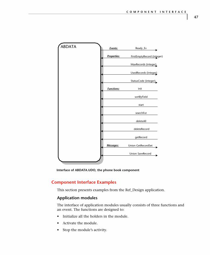
C O M P O N E N T I N T E R F A C E
47
Component Interface Examples
This section presents examples from the Ref_Design application.
Application modules
The interface of application modules usually consists of three functions and an event. The functions are designed to:
• Initialize all the holders in the module.
• Activate the module.
• Stop the module’s activity.
Union SaveRecord
Union GetRecordSet
init
deleteAll
Ready_EvABDATA
deleteRecord
getRecord
FirstEmptyRecord (integer)
StatusCode (integer)
MaxRecords (integer)
UsedRecords (integer)
sortByField
searchFor
start
Functions:
Events:
Properties:
Messages:
Interface of ABDATA.UDO, the phone book component

A R C H I T E C T U R E D E S I G N
48
The event is designed to notify the parent application that the module’s activity has stopped and that it is back in idle state.
The call management application module CALLHMI exemplifies this type of interface as shown in the following illustration:
The function initCallHMI allows the main application to initialize the component with the appropriate arguments. The initialization of fonts is performed by a separate function because when the cell phone user selects a different language only the fonts need to be adjusted accordingly. The functions start and stop make it possible for the main application to start and stop the component’s functionality. The component uses the exit_Ev event to notify the main application that it has stopped its activity and returned to idle state. Since the main application serves as a task manager, it needs to know when it can safely allocate shared resources to a different component.
Service components
Service components do not have a typical interface. Their interface is determined for each component on the basis of its functionality requirements and the developer’s judgement.
The following illustrations present the interfaces of two service components.
start
initCallHmi
exit_EvCALLHMI Events:
Functions:
stop
initFonts
Interface of CALLHMI.UDO, the call management component
start
initIconsICONS
stop
Functions:
Interface of ICONS.UDO, the service component that displays icons
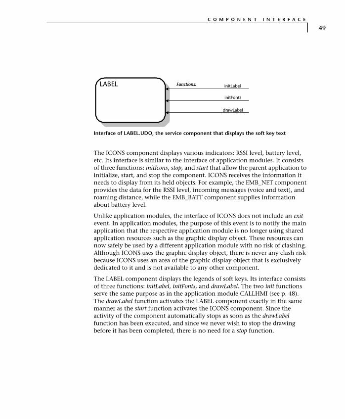
C O M P O N E N T I N T E R F A C E
49
The ICONS component displays various indicators: RSSI level, battery level, etc. Its interface is similar to the interface of application modules. It consists of three functions: initIcons, stop, and start that allow the parent application to initialize, start, and stop the component. ICONS receives the information it needs to display from its held objects. For example, the EMB_NET component provides the data for the RSSI level, incoming messages (voice and text), and roaming distance, while the EMB_BATT component supplies information about battery level.
Unlike application modules, the interface of ICONS does not include an exit event. In application modules, the purpose of this event is to notify the main application that the respective application module is no longer using shared application resources such as the graphic display object. These resources can now safely be used by a different application module with no risk of clashing. Although ICONS uses the graphic display object, there is never any clash risk because ICONS uses an area of the graphic display object that is exclusively dedicated to it and is not available to any other component.
The LABEL component displays the legends of soft keys. Its interface consists of three functions: initLabel, initFonts, and drawLabel. The two init functions serve the same purpose as in the application module CALLHMI (see p. 48). The drawLabel function activates the LABEL component exactly in the same manner as the start function activates the ICONS component. Since the activity of the component automatically stops as soon as the drawLabel function has been executed, and since we never wish to stop the drawing before it has been completed, there is no need for a stop function.
drawLabel
initLabelLABEL
initFonts
Functions:
Interface of LABEL.UDO, the service component that displays the soft key text

A R C H I T E C T U R E D E S I G N
50
Here is the interface of the KEYPAD continuous service component.
The KEYPAD component mediates between the EMB_KPD component and the application. It translates the events received from EMB_KPD and converts them into events that are meaningful to the application. It also expands the functionality of EMB_KPD by adding a distinction between short and long key presses.
In the KEYPAD component, we use a pair of events: short and long for each of the control keys. For the alphanumeric keys, we use two generic events: short and long accompanied by the LastKey property, which indicates the value of the key that has been pressed. The different treatment of the two key types corresponds to the difference in their functionality: the control keys execute various operations while the alphanumeric keys are used in editing. Therefore, the values of the alphanumeric keys can be meaningfully used by the editor, but there is no such use for the values of the control keys.
The ControlKey_Short event provides a way of referring to any key in the group of control keys. This event is helpful in implementing the backlight mechanism.
ControlKey_Short
LastKey (integer)
AlphanumericKey_Long
AlphanumericKey_ShortKEYPAD Events:
Properties:
Event short for each control key:ArrowDown_ShortArrowUp_ShortEnd_ShortLeft_ShortRight_ShortSend_ShortVolumeDown_ShortVolumeUp_Short
Event long for each control key:See above list
Interface of KEYPAD.UDO, the continuous service component that wraps around the embedded keypad component

R A P I D A N D S Y S T E M A R C H I T E C T U R E
51
RAPID AND SYSTEM ARCHITECTURE
System architecture considerations mainly affect the integration of the Rapid generated code, but should be considered during the design stage as well. These include task architecture, task communication and memory allocation, task priority, and the distribution of resources among tasks and components.
Task Architecture
Rapid usually executes as a single task. In order to interface with other software, you should define suitable interfaces in Rapid’s embedded interface components. The best way to implement interface between Rapid and software running in a different task is via message interface.
Sometimes, a Rapid application contains a user object whose main purpose is to provide graphic functionality via a graphic display object. This graphic functionality can be split from the main task into a separate task (for details, see “Code generation of an “Empty task”” on p. 53). Full multi-tasking support is planned for RapidPLUS CODE version 7.01.
Rapid API must be called only from the Rapid task.
Inter-Task Communication and Memory Allocation
Memory allocation for interface messages
When a message is used in an embedded interface component, memory for its data can be allocated either statically or dynamically:
• Static allocation (buffer type) is performed by Rapid and is the default memory allocation method. Rapid internally allocates for each union a buffer that is large enough to accommodate the union’s largest structure.
• Dynamic allocation (pointer type) uses memory that is provided by the underlying embedded system and is identified by a pointer.
In a message that uses buffer-type memory, the data is copied from the embedded structure into the buffer after a message using the generated API has been sent to the Rapid application. In a message that uses dynamically allocated memory, the data is not copied; rather, the actual buffer is used by Rapid.

A R C H I T E C T U R E D E S I G N
52
Message allocate/free policy
When dynamic allocation is used, rules for the allocation and release of memory should be defined. When a message that includes data is sent from one task to another, these rules make it clear which task is responsible for releasing the allocated memory.
When the allocation policy states that it is the responsibility of the message-receiving task to free the allocated memory, pointer-type messages are the best type of interface. The code generated for the deactivate function of a message includes a user code section that can be employed to release memory that is no longer required by Rapid.
Rapid Task Priority
The Rapid application normally deals with user interface issues involving multiple display activities. It is the nature of such activities to consume considerable CPU resources. In order to avoid performance degradation, the Rapid task should be assigned a relatively low priority.
Starvation of the System
In non-preemptive multitasking systems, programmers need to break long operation sequences into smaller units in order to avoid “starvation” of other tasks. Since the Rapid state machine works in cycles, the Rapid developer does not need to address this issue. At integration time, the system integrator can program the Rapid task to call for rescheduling after each cycle. Thus, the execution of a long loop based on the Rapid state machine will not bring the entire embedded system to a halt. The execution of the logic will be automatically “sliced” by Rapid into state machine cycles.
The number of Rapid state machine cycles performed in each “task cycle” (i.e., during the processing of a message received by the task) should be fine-tuned during integration. For additional information, see “Limiting the Number of Consecutive State Machine Cycles” on p. 86.
UI Required in Different Tasks
Rapid application execution is based on a state machine model. The state machine supports concurrency by using concurrent modes and by assigning concurrent logic to separate components. Sometimes, however, user interface services are required by external software that is executed in different tasks.
R A P I D A N D S Y S T E M A R C H I T E C T U R E
53
For such cases, the following architecture solutions are available:
• The Rapid task will provide user interface services to other tasks.
• A separate task will provide user interface services to the Rapid task and to other tasks. In this case, generation of a component as an empty task can be used to develop this task in Rapid.
Code generation of an “Empty task”
This approach is especially useful for systems with a graphic display, in which the display functionality runs in its own task in order to serve several applications running in different tasks (such as a WAP browser). Rapid’s graphic display object (GDO) implements the functionality of a graphic display.
Rapid supports code generation for the GDO by supplying C language graphic libraries and generating code that uses them. To facilitate this, Rapid allows users to generate code for user objects that includes only their objects and functions (with some limitations) without the state machine functionality (generate as an “Empty Task”). This means that the generated user object can use Rapid’s objects, but does not incur the cost of the state machine engine.
For more information , see “User objects generated as empty tasks” on p. 20.
Timer Integration
The Rapid application must be integrated to a timer service provided by the embedded system. Two types of APIs are available: continuous timer update and update timer on request. The type used is determined by the design of the embedded system.
The update timer on request API should be used for a system that implements sleep mode (for saving batteries).
If continuous timer update API is used, the timer service should send a message to the Rapid task in a predefined frequency. This frequency can be defined based on performance issues. Frequency should be high enough for the timers defined in the application to work correctly, but not too high in order to avoid degradation of system performance.
When the Rapid task receives a message (or other notification) from the timer service, an additional state machine cycle should be executed so that internal logic not related to user input (condition-only transitions, mode activities, and transitions based on generated events) will be performed. The function, rpd_PrivUpdateTimer, can be called to execute the additional state machine cycle.

A R C H I T E C T U R E D E S I G N
54
DESIGN REVIEW
When the architecture of the application has been completed, the list of components and their hierarchy must be reviewed and approved by the various participants in the project. It is essential for the review forum to include at least one senior representative of each of the groups involved in the project.
The format of the review and approval may vary from one organization to another, and can be conducted in any way that is convenient to the participants. The design review is an essential step before moving on to the implementation stage because it provides a final opportunity for detecting flaws in the design when corrections are still relatively easy and inexpensive to make.

55
C H A P T E R 4
ImplementationThe output of the architecture design is a hierarchical list of the application components including descriptions of the functionality and interface of each component. During the implementation stage, each component “comes to life” as a Rapid user object with its objects, mode tree, logic, and interface.
This chapter presents information on:
• Setting implementation priorities.
• The implementation procedure for individual components.
• Tips for fine-tuning the implementation.

I M P L E M E N T A T I O N
56
SETTING IMPLEMENTATION PRIORITIES
Implementation of the various components should be a bottom-up process. You should start with the lowest-level components (embedded interface components) and move up the component hierarchy. This direction is dictated by Rapid’s modular and hierarchical structure.
A component that uses other components cannot be implemented as long as they are not available. Implementation should therefore start with the embedded interface components, proceed to continuous and on-demand services, go on to the application modules, and culminate in the creation of the main application.
A component can be integrated into another component as soon as its interface is ready, even if its internal logic has not yet been written. In order to expedite implementation of higher-up components, the implementation of each component should start with its interface, and then continue with its internal logic. The idea is to create the skeleton of the application as soon as possible, then go back and fill in its functionality.
In completing the functionality of each component, the general principle for implementation priorities is to move from the most significant elements to the less significant ones. For example, a call module will first implement outgoing/incoming calls, then call waiting, then conference calls, and so on. Within each element, you should start by implementing the minimum, basic functionality, then continue to elaborate on it. For example, in a phone book application, you will first implement the retrieval and presentation of entries to allow other modules to get data from the phone book (e.g., the call module will get the number to call), then you will add logic for entering, deleting, and changing data in the phone book.
The Application Properties window provides a simple tool for version control of the individual components (refer to the section “Using the Application Properties Window” in Chapter 1 of the User Manual Supplement).
Assuming that implementation is a group effort and that each component may be used in several others, a procedure that controls the availability and update of components as they are progressively implemented is of the utmost importance. One way to achieve such control is by creating a component bank that is managed by a single person and is updated at set intervals. Another option is to use the organization’s configuration management tools with its check out/check in mechanism.

I M P L E M E N T I N G C O M P O N E N T S
57
IMPLEMENTING COMPONENTS
In this section you will read about implementation steps common to all components, implementation of embedded interface components, implementation of service components, implementation of graphic display objects (GDO), and implementation of holders.
Component Implementation Procedure
For each application component, apply the following implementation steps:
1. Create the component’s interface.
2. Write the component’s logic.
Follow the priorities presented in the preceding section. Verify that all the objects and functions you use can be generated (refer to Appendix C: “Generated and Nongenerated Elements” in the Generating Code manual).
3. Consider maintenance and optimization.
Follow these basic rules to improve maintenance and optimize the generated code:
• Add comments to your logic to make it easier to understand.
TIP: Precede each user function with a comment that describes it. When you generate the Object Interface report, the comments are included.
• Build user functions when appropriate.
When the same logic is used in several places, it is useful to encapsulate it as a user function, with or without arguments. Instead of having to rewrite the entire block each time, the user function can be called.
Replacing repeated logic by user functions has the additional advantage of simplifying maintenance. You can also employ user functions to streamline the logic and make it more readable. For example, you can create a user function that encapsulates all the initialization activities.
• Use as many modes are necessary to create a readable mode tree.
Modes make your logic more readable and—when used correctly— improve performance. They consume very little memory.

I M P L E M E N T A T I O N
58
• Set an appropriate size limit for each data object.
Set default string and array size limits in the Data sizes tab of the Code Generation Preferences dialog box. When possible, reduce the size of individual strings and arrays to economize memory usage.
❖ NOTE: Rapid default size limits are environment-dependent (stored in the Rapidx.ini file) and may change when you switch from one computer to another.
4. Run the Verification test when implementation has been finalized. Remove unreferenced objects and solve detected logic problems.
5. Build a test application and test the component. For each component, build a test application and test all the interfaces and functionality before integrating the component.
Implementing Embedded Interface Components
Embedded interface components fall into two groups: user interface (UI) components such as the keypad and the display, and non-UI components such as the cell phone’s battery, the protocol stack, and the radio signal strength indicator. To allow the user to control non-UI interface elements, you could create a simulation panel. For example, you could add a potentiometer to manipulate the signal strength and several buttons to send protocol stack messages.
Implementing the full functionality of the simulation panel is costly and unnecessary. Leaving the functionality of these components altogether out of the simulation and postponing testing of their input/output until the application is integrated into the embedded system is extremely risky.
TIP: When using a simulation panel, implement only the minimal functionality necessary to produce an appropriate data output for the application. The minimal functionality should be sufficient for testing the application’s functionality already in the simulation environment.
The simulation panel is usually implemented as several embedded interface components and uses interface elements to communicate with the Rapid application. Thus, not only the application’s functionality but also its interfaces can be tested. During code generation, the internal logic of these components—generated as interface only—is ignored, and only their interface elements are generated.
When the simulation panel is distributed among several embedded interface components, and the various components need to communicate with each

I M P L E M E N T I N G C O M P O N E N T S
59
other, Rapid’s DDE or Applink objects can be used to establish such communication without requiring extra interface elements.
Implementing Services
Unlike continuous services whose functionality is always available, on-demand services alternate between the idle and active states, and their functionality is available only in the latter. This difference affects the implementation of the two types of components, and is reflected in their mode trees.
On-demand services typically have a mode in which the service is dormant (in the Ref_Design application, this mode is named “idle”, but you can use the name of your choice) and a mode in which the service is active (“active” in Ref_Design). The transition from idle mode to active mode is triggered by a specific event (a function call or a message from the parent)—the demand for the service—following which the functionality of the service becomes available. When the service has been completed or is no longer required, it returns to idle mode.
Continuous services, whose functionality is always available, do not have an idle mode. If it were not for the use of holders, the default mode of continuous services would be “active”. Rapid commonly uses holders for shared components to avoid multiple instances of the same component. Consequently, both continuous and on-demand services have an initialization mode (named “init” in the Ref_Design application) as their default mode. The purpose of this mode is to verify that the service’s holders have been initialized (i.e., assigned instances of the user objects) before a transition into idle mode (in on-demand services) or active mode (in continuous services) is allowed to take place.
The basic mode tree of on-demand services typically consists of three modes: init, idle, and active. The basic mode tree of continuous services typically consists of two modes: init and active.
Implementing the Graphic Display Object
At this stage of development, it is usually known whether the display is to be implemented by Rapid’s graphic display object (GDO) or by an embedded interface component that will be simulated in Rapid.
When using a GDO, you need to determine the number and size of the GDO’s buffers and define its update mode. These decisions affect the manner in which logic involving the GDO is written as well as the object’s resource usage and response time, and should therefore be given careful consideration.
I M P L E M E N T A T I O N
60
Number and size of buffers
For each GDO, Rapid allocates an intermediate buffer whose memory size is determined by the number of pixels and color depth of the GDO. In addition, you can define additional GDO buffers of variable sizes. Using buffers is very convenient. By saving the content and status of the GDO (including the current font) into a buffer, you keep it available for immediate re-display. The price paid for this convenience is in RAM consumption. Each buffer requires its own memory allocation—the bigger the buffer, the larger the required allocation.
When a fixed, small section of the display is reserved for the exclusive use of a given component—for example, the area reserved for informational icons on a cell phone’s display—then you can limit the size of the additional buffer to the respective display area, and so enjoy the advantage of a dedicated buffer without unduly increasing resource consumption.
Update method
All drawing on the GDO is first performed on a buffer (the intermediate buffer or a user-defined buffer), then copied to the embedded display. By default, the GDO is in “immediate update” mode, i.e., the display is automatically updated after each drawing operation. However, you can change the update mode to “update on request”, i.e., the GDO is updated only after an update function is used. In “update on request” mode, many draw operations can take place before the GDO is updated. The GDO’s update mode can be changed during runtime.
The “update on request” mode can eliminate flickering and can improve the GDO’s refresh rate when changes are made on a relatively restricted area of the display. For example, you might have a series of primitive graphic elements being drawn near one another on the GDO. Or, you might have different user objects that draw on different buffers. In these situations, it would be good practice to put the GDO in “update on request” mode and call the update function at the end of the sequence of draw operations. See the following illustration.
On the other hand, if your incremental changes are widely distributed over the display, the efficiency of “update on request” mode is seriously undermined and “immediate update” mode may give better results. The reason is that each time you call the update function, Rapid redraws the area within the smallest possible bounding box that encloses all the changes made since the last update. If the changes are in opposite corners of the GDO, the redraw area spans almost the entire GDO. In this case, it would be better to work in “immediate update” mode, whereby Rapid only redraws the small area that has changed as the result of each draw operation.
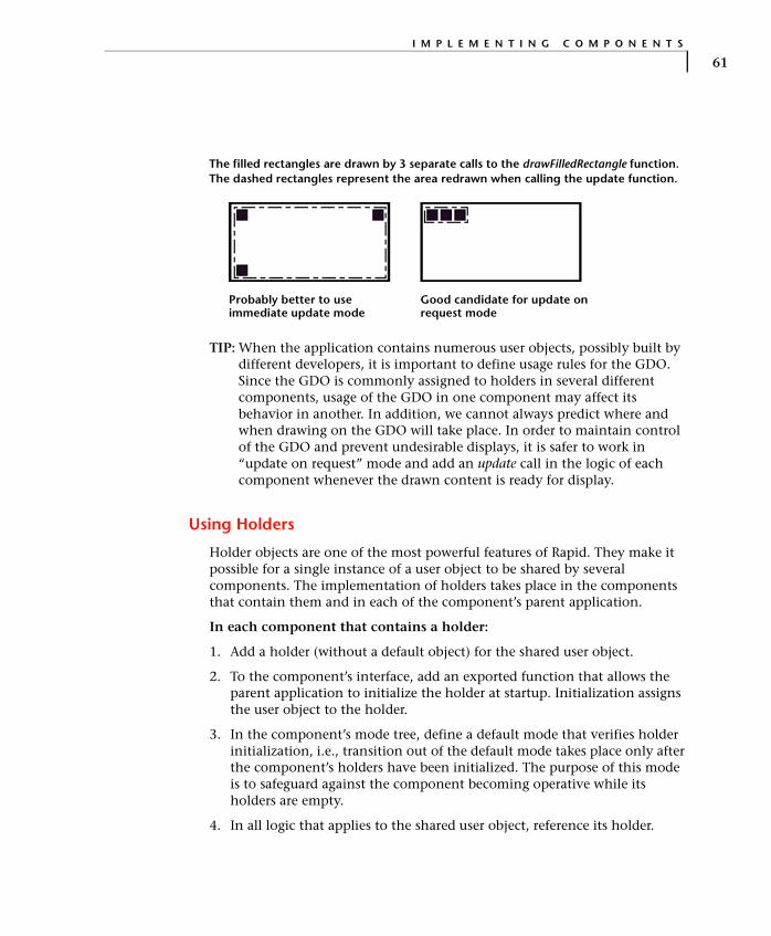
I M P L E M E N T I N G C O M P O N E N T S
61
TIP: When the application contains numerous user objects, possibly built by different developers, it is important to define usage rules for the GDO. Since the GDO is commonly assigned to holders in several different components, usage of the GDO in one component may affect its behavior in another. In addition, we cannot always predict where and when drawing on the GDO will take place. In order to maintain control of the GDO and prevent undesirable displays, it is safer to work in “update on request” mode and add an update call in the logic of each component whenever the drawn content is ready for display.
Using Holders
Holder objects are one of the most powerful features of Rapid. They make it possible for a single instance of a user object to be shared by several components. The implementation of holders takes place in the components that contain them and in each of the component’s parent application.
In each component that contains a holder:
1. Add a holder (without a default object) for the shared user object.
2. To the component’s interface, add an exported function that allows the parent application to initialize the holder at startup. Initialization assigns the user object to the holder.
3. In the component’s mode tree, define a default mode that verifies holder initialization, i.e., transition out of the default mode takes place only after the component’s holders have been initialized. The purpose of this mode is to safeguard against the component becoming operative while its holders are empty.
4. In all logic that applies to the shared user object, reference its holder.
The filled rectangles are drawn by 3 separate calls to the drawFilledRectangle function. The dashed rectangles represent the area redrawn when calling the update function.
Probably better to use immediate update mode
Good candidate for update on request mode
I M P L E M E N T A T I O N
62
In the parent application:
1. Add a single instance of the shared user object.
2. At startup, initialize the holders of the shared user object by calling the initialization exported function of the relevant components.
An alternative holder initialization method is to use the holder’s holdNew function to generate its object dynamically during runtime. When this type of initialization is used, it is not necessary to apply the initialization steps described in the steps above (steps 2 and 3 in the component implementation and steps 1 and 2 in the parent application implementation).
Dynamic generation of a holder’s object can be used to reduce RAM usage, especially when the held object is not constantly in use. When no longer needed, the held object should be removed by using the holder’s clear function. Holders of objects that are continuously used—such as the holder of a keypad component in a cell phone application—should never be cleared.
IMPLEMENTATION TIPS
The information in this section helps you polish the implementation in order to improve performance both in the simulation and the embedded system environments, to minimize the size of the generated application, and/or to enhance the application’s maintainability.
Verification Test
Once the implementation is in its final stages, you should run a verification test, as described on pp. 12-38 to 12-42 of the Rapid User Manual. The verification test notifies you about modes that cannot be reached or exited, transitions without triggers, ambiguous transitions, and objects that are not referenced by the logic. Use these warnings to delete superfluous logic elements from the application.

I M P L E M E N T A T I O N T I P S
63
Code Generation Messages
During code generation, the Code Generator builds and displays a log of the code generation process. The log includes errors, warnings, and messages that are important for troubleshooting code generation difficulties. For details, refer to Appendix E, “Errors, Warnings and Messages” in the Generating Code manual.
The code generation log includes messages about unreferenced objects, commented out logic lines, and unused user functions that were ignored during code generation. Use these messages to eliminate unnecessary logic and objects from the application.
Modes vs. Conditions
A basic rule in Rapid application development is to control the flow of system behavior through mode sequences rather than complex condition-checking. For example, you might have a situation in which the user enters a three-character alphanumeric string, and the format of each character or digit needs to be validated before the system enters the next mode.
One possibility would be to build a complicated condition trigger that checks all three characters, along the lines of: & Str1[1] = x and Str1[2] = y and Str[3] = z. However, in order to improve performance and enhance maintainability, it is preferable to build a small subtree as shown below:
& Str1[1] = x
& Str1[2] = y
& Str1[3] = z takes you to the appropriate mode when the code is valid
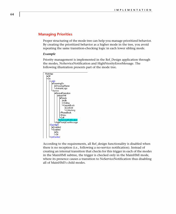
I M P L E M E N T A T I O N
64
Managing Priorities
Proper structuring of the mode tree can help you manage prioritized behavior. By creating the prioritized behavior as a higher mode in the tree, you avoid repeating the same transition-checking logic in each lower sibling mode.
Example
Priority management is implemented in the Ref_Design application through the modes, NoServiceNotification and HighPriorityErrorMessage. The following illustration presents part of the mode tree.
According to the requirements, all Ref_design functionality is disabled when there is no reception (i.e., following a no-service notification). Instead of creating an internal transition that checks for this trigger in each of the modes in the MainHMI subtree, the trigger is checked only in the MainHMI mode, where its presence causes a transition to NoServiceNotification thus disabling all of MainHMI’s child modes.

I M P L E M E N T A T I O N T I P S
65
Another requirements specification of Ref_Design is that high-priority error messages such as a “low battery” message disable all functionality including the display of the no-service notification. Instead of adding logic that checks for this trigger in both branches of the NormalOperation subtree, this trigger is checked only in the NormalOperation mode, where its detection brings about a transition into the HighPriorityErrorMessage mode and disables all the child modes of NormalOperation.
The following state chart clarifies how the hierarchy in the Active and MainHMI subtrees manages the priorities described above.
Active has two child modes: NormalOperation and HighPriorityError-Message. When a transition from NormalOperation to its sibling HighPriorityErrorMessage takes place, it shuts off access to the child modes of NormalOperation. Similarly, the transition from MainHMI to its sibling NoServiceNotification closes the passage from MainHMI to its child modes.
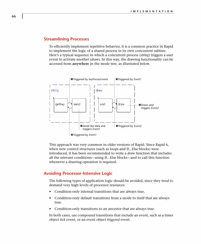
I M P L E M E N T A T I O N
66
Streamlining Processes
To efficiently implement repetitive behavior, it is a common practice in Rapid to implement the logic of a shared process in its own concurrent subtree. Here’s a typical sequence in which a concurrent process (string) triggers a user event to activate another (draw). In this way, the drawing functionality can be accessed from anywhere in the mode tree, as illustrated below.
This approach was very common in older versions of Rapid. Since Rapid 6, when new control structures (such as loops and If...Else blocks) were introduced, it has been recommended to write a draw function that includes all the relevant conditions—using If...Else blocks—and to call this function whenever a drawing operation is required.
Avoiding Processor-Intensive Logic
The following types of application logic should be avoided, since they tend to demand very high levels of processor resources:
• Condition-only internal transitions that are always true.
• Condition-only default transitions from a mode to itself that are always true.
• Condition-only transitions to an ancestor that are always true.
In both cases, use compound transitions that include an event, such as a timer object tick event, or an event object triggered event.
�Triggered by keyPressed event �Triggered by Event1
�Draws and triggers Event2
�Triggered by Event2�Sends the data and triggers Event1
�Triggered by Event1

I M P L E M E N T A T I O N T I P S
67
Blocking Operations and Loops
Loops can be implemented in Rapid in the following two ways:
• For/While logic blocks.
• Modes and internal condition-only transitions.
For/While logic blocks are executed as a single unit in a single cycle of the state machine. For the duration of this cycle, no other events or logic can be processed in the entire application.
When using modes and an internal condition-only transition, it requires several state machine cycles to complete the loop, but it never blocks input from other parts of the system.
For/While blocks should be used when the loop can be completed in a short time, as is usually the case. When the loop is very long or when completion of its activities may take long (e.g., reading data from flash memory), it is preferable to use modes and a condition-only transition.
Objects
When building an application for code generation, there are certain issues to consider when choosing which objects to use and how to use them.
Simulation-only objects
At the most basic level, bear in mind that not all Rapid objects and functions are supported for code generation. (Refer to Appendix C: “Generated and Nongenerated Elements” in the Generating Code manual for a comprehensive list of supported objects and functions.) All such objects should be encapsulated in user objects to be generated as interface only.
❖ NOTE: The code generation log warns you about functions, objects, and properties used by the application that could not be generated. Such warnings may or may not be followed by improper application performance and should be investigated before compiling and linking the code.
When a user object has been generated as interface only, its exported functions (generated as empty functions) have to be implemented. For

I M P L E M E N T A T I O N
68
example, a user object named MYOBJECT may have an exported function that looks as follows in the Function Editor:
In the user object’s generated .c file, the function looks as follows:
void MYOBJECT_R3245_incrementCounter_ ( pMYOBJECT udo,RapidInteger* Parm_Integer1)
{/******* RapidUserCode BEGIN MYOBJECT_incrementCounter_ ********//******* RapidUserCode END MYOBJECT_incrementCounter_ ********/
}
Using the integer object manipulation functions, the exported function would be implemented in the user code area as follows:
/******* RapidUserCode BEGIN MYOBJECT_incrementCounter_ ********/RapidInteger_set (Parm_Integer1, RapidInteger_get(Parm_Integer1)+1);/******* RapidUserCode END MYOBJECT_incrementCounter_ ********/
For a list of the functions available to the embedded system programmer for manipulating Rapid objects that are passed as parameters by exported functions, refer to Appendix F: “RapidPLUS Object Manipulation Functions” in the Generating Code manual.
Object “weight” in the generated code
See Appendix A: “Memory Consumption” for important information on the relative impact of various objects on the size of the generated code. When the generated application size is an issue, you can use this information to optimize object usage in the simulation application.

69
C H A P T E R 5
OptimizationThe importance of optimizing code sizes and performance has been emphasized throughout the application building process. Commonly, the resources available to the Rapid task are limited and constitute a constraint with which the Rapid task must comply. It is therefore advisable to start resource monitoring as early as possible. Such monitoring can be applied even to individual components, although it may be difficult to interpret the data in isolation. Certainly, the analysis of resource usage should be undertaken as soon as the various components are combined to make up the application, even before all of its functionality has been implemented.
Resource optimization must be an ongoing process, reaching its final stage when the application is integrated in the embedded system, and culminating in an application that does not exceed its resource budget. Performance checks are not very meaningful outside the embedded system environment. However, they too should be applied as early as possible. Obvious performance-slowing elements, such as very long or very high-frequency loops, can already be detected in the simulation environment. Where response times are crucial, particularly when they are detailed in the requirements specification, integration should be performed at an early stage, so that performance data can be obtained and improved if necessary.
Once the need for optimization is established, you can use a variety of diagnostic tools to identify objects with excessive resource usage, then analyze these objects to pinpoint where and how optimization can best be applied.
This chapter presents information about:
• Diagnostic tools for analyzing resource usage and performance.
• Techniques for optimizing RAM usage.
• Techniques for optimizing ROM usage.
• Ways to improve performance.
• An optimization case study.

O P T I M I Z A T I O N
70
MEMORY USAGE DIAGNOSTIC TOOLS
Rapid and the development environment provide several diagnostic tools that identify code areas that require optimization. These tools are:
• The Rapid Object Data report.
• The Rapid RAM Size Report utility.
• The linker-produced map file for RAM and ROM information.
• Performance information obtained from Rapid’s Debugger and Logger tools.
Rapid’s Object Data Report
This report provides information about the objects in the component, and can help identify objects with excessive sizes. Its great advantage is that it is produced directly from Rapid (Reports|Objects|Data) and requires no linking or code generation.
The following illustration shows an excerpt from an Object Data report. The circled area alerts you to the fact that the size of the string has not been limited and that the Code Generator will apply to it the default string size. If you know that this string requires a smaller size, you may decide to change the string definition accordingly.

M E M O R Y U S A G E D I A G N O S T I C T O O L S
71
The Rapid RAM Size Report Utility
The RAM Size Report provides RAM usage information for the Rapid task of the embedded system. It is produced by a Rapid-provided utility that uses the output of the Code Generator. For a full description of the report and detailed instructions on how to produce it, refer to the RAM Size Report document located in the Manuals folder of Rapid.
The RAM Size Report is available in detailed and summary formats. The summary format presents a line of information for each component of the application, and should be sufficient to alert you to unexpected or excessive RAM sizes. In large applications, you might find it useful to import the report into a program that provides sorting options, such as Microsoft® Excel, and

O P T I M I Z A T I O N
72
sort the objects by size. You should start your analysis with the highest RAM components and proceed to those that require less RAM.
The following illustration presents an example of the summary report.
For a detailed analysis of RAM usage in individual components, you can use the detailed format. This format breaks down RAM usage by individual component objects.
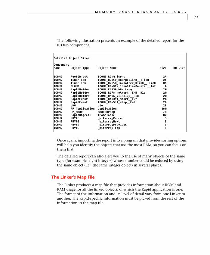
M E M O R Y U S A G E D I A G N O S T I C T O O L S
73
The following illustration presents an example of the detailed report for the ICONS component.
Once again, importing the report into a program that provides sorting options will help you identify the objects that use the most RAM, so you can focus on them first.
The detailed report can also alert you to the use of many objects of the same type (for example, eight integers) whose number could be reduced by using the same object (i.e., the same integer object) in several places.
The Linker’s Map File
The Linker produces a map file that provides information about ROM and RAM usage for all the linked objects, of which the Rapid application is one. The format of the information and its level of detail vary from one Linker to another. The Rapid-specific information must be picked from the rest of the information in the map file.
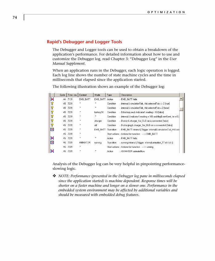
O P T I M I Z A T I O N
74
Rapid’s Debugger and Logger Tools
The Debugger and Logger tools can be used to obtain a breakdown of the application’s performance. For detailed information about how to use and customize the Debugger log, read Chapter 3: “Debugger Log” in the User Manual Supplement.
When an application runs in the Debugger, each logic operation is logged. Each log line shows the number of state machine cycles and the time in milliseconds that elapsed since the application started.
The following illustration shows an example of the Debugger log:
Analysis of the Debugger log can be very helpful in pinpointing performance- slowing logic.
❖ NOTE: Performance (presented in the Debugger log pane in milliseconds elapsed since the application started) is machine dependent. Response times will be shorter on a faster machine and longer on a slower one. Performance in the embedded system environment may be affected by additional variables and should be measured with embedded debug features.

M E M O R Y U S A G E D I A G N O S T I C T O O L S
75
The Debugger log can also be used to identify continuous loops. In the illustration below, the loop consists of the following lines:
The loop lines, as seen in the illustration, may be consecutive or interspersed by other logic.
A variety of filters can be applied to the Debugger to focus on selected components and produce a more compact and easier-to-read log. When analyzing performance, you should also filter out all the internal logic of embedded interface components, since they will be ignored by the Code Generator.
Condition internal;& Integer1 <= 5 [true]
Transition myApplic internal [ Trigger: internal;& Integer1 <= 5 [true]
Start actions Actions for transition: -----> myApplic
Action Integer1 := 2
O P T I M I Z A T I O N
76
OPTIMIZING RAM
RAM usage is primarily determined by the manipulation of variable data in the application (application variables and state machine queues). Because RAM is usually a limited resource, the Rapid application must operate within the RAM constraints imposed on it by the embedded system. Rapid offers several options for generating code that uses less RAM. In addition, there are a variety of RAM-reducing alternatives that can be applied when it is necessary to lower RAM consumption.
The following sections list various ways of decreasing the application’s RAM usage. Some of these techniques exploit Rapid built-in mechanisms; others require manual changes in the application.
Setting Code Generation Preferences to Reduce RAM
Several parameters in the Code Generation Preferences dialog box affect RAM usage of the generated code:
• Generation of unused elements (Optimizations tab).
• Maximum data object sizes (Data sizes tab).
• Maximum buffer sizes (Buffer sizes tab).
Excluding unused elements
You can reduce the required RAM size by excluding objects that are not used by the application logic from code generation. To exclude unused elements, clear the “Generate unused elements” option. Non-generation of unused objects also reduces ROM usage.
In some situations, you may want to include unused elements in the generated code. For example, in order to get an idea of the size of the generated code before you have implemented all mode-related logic. However, when generating code for the completed application, you should always verify that the “Generate unused elements” option is not selected.
Setting appropriate data size limits
The sizes of Rapid data objects: string, array, and data store can be limited for code generation. These sizes will be used by the Code Generator and will determine the allocation of RAM for the objects.
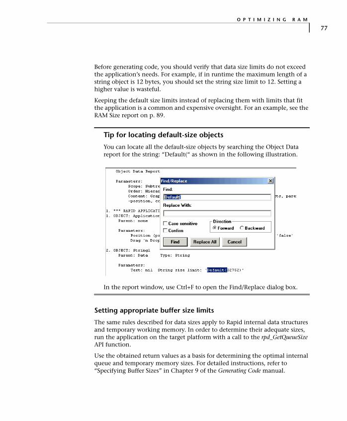
O P T I M I Z I N G R A M
77
Before generating code, you should verify that data size limits do not exceed the application’s needs. For example, if in runtime the maximum length of a string object is 12 bytes, you should set the string size limit to 12. Setting a higher value is wasteful.
Keeping the default size limits instead of replacing them with limits that fit the application is a common and expensive oversight. For an example, see the RAM Size report on p. 89.
Tip for locating default-size objects
You can locate all the default-size objects by searching the Object Data report for the string: “Default(“ as shown in the following illustration.
In the report window, use Ctrl+F to open the Find/Replace dialog box.
Setting appropriate buffer size limits
The same rules described for data sizes apply to Rapid internal data structures and temporary working memory. In order to determine their adequate sizes, run the application on the target platform with a call to the rpd_GetQueueSize API function.
Use the obtained return values as a basis for determining the optimal internal queue and temporary memory sizes. For detailed instructions, refer to “Specifying Buffer Sizes” in Chapter 9 of the Generating Code manual.
O P T I M I Z A T I O N
78
Excluding Non-Referenced Interface Elements
Although objects that are not used in the component’s logic can be automatically excluded from code generation, interface elements that are not used in the application must be manually removed. Normally, a component’s interface is defined before its implementation and, in many cases, is designed to support future functionalities. At the optimization stage, you should decide whether to keep or remove unused interface elements. Removal of unused interface elements improves ROM usage as well.
Generating Rapid Data Objects as Primitives
Integer, number, and string objects can be generated either as primitives or as Rapid objects. Generation as Rapid objects produces a structure that contains data required by Rapid for the object manipulation and the object’s value. Generation as a primitive produces a variable (RLONG for an integer, RFLOAT for a number, and RCHAR for a string) with its value. Generation of integers, numbers, and strings as primitives saves both RAM and ROM.
The type of generation is determined by the Code Generator on the basis of the object’s use in the application. A Rapid integer/number is generated as a primitive when all the following statements are true:
• It is not used on the right side of an assign (:=) function in mode activities.
• It is not used in user condition functions.
• It is not passed as an argument to a user function that could changes its value (i.e., passed by address).
• It is not bounded.
To economize resource consumption, avoid using integers, numbers, and strings in the above listed circumstances, unless necessary. Verify that the Bounded option (in the More dialog box of an integer and a number) is selected only when required.
Replacing Interface Messages by Data Containers
❖ NOTE: The following information applies to service and application module components.
Using messages to interface between components is expensive in RAM usage because memory for the message is allocated both in the component where the message is defined and in its parent application. When the send/receive mechanism of the message is not needed, it is more economical to replace the message by a data container.

O P T I M I Z I N G R A M
79
Using a data container instead of a message requires an allocation of memory only in the parent application. However, the addition of another user object entails the standard RAM overhead required by any component. When the memory saved by elimination of the dual memory allocation is larger than the memory expended on the additional component, replace the message interface by a data container.
For more information about data containers, see “User objects generated as data containers” on p. 20.
Sharing Data by Using Data Containers
When the same data is shared by several components, it is more economical to create a data container for the shared data in the parent application than to define it in each of the components. To make the data in the data container accessible to other components, you should define an appropriate holder in each of the respective components. The holder must be initialized by the parent application.
For more information about holders, see “Using Holders” on p. 61.
Allocating Message Memory by Pointer
Memory for a message is allocated by one of two methods:
• Buffer, whereby Rapid internally allocates each union enough memory to accommodate its largest structure. This is the default method.
• Pointer, whereby the user object message uses memory that is provided by the underlying embedded system. For instructions on how to change the memory allocation method, refer to the section “Adding Unions and Structures” in Chapter 16: “Adding Messages to a User Object” of the User Manual Supplement.
Pointer-type messages can be used in order to share memory between Rapid and the embedded system. In order to avoid data loss when memory is controlled by the embedded system, message data must be used before a new message arrives from the embedded system, or copied for later use into a Rapid-controlled memory area.
If the system allocation policy specifies that freeing the allocated memory is the responsibility of the message-receiving task, the deactivateAny function should be called by the Rapid application. The Rapid kernel then calls the deactivate function for the active structure. In the user code of this function, the integrator should add a call to a function that frees the allocated memory.

O P T I M I Z A T I O N
80
Using Dynamic Memory Allocation
Rapid supports dynamic memory allocation for user objects. In systems that support dynamic memory allocation, the entire user object can be created during runtime. This is achieved by using a holder of the user object’s type and calling the holder’s holdNew function when an instance of the user object is required. Rapid then allocates memory for the user object and creates an instance of it. When dynamic allocation is used, the memory is automatically released by the Rapid garbage collector as soon as no holder points to the user object or any of its children.
Replacing Timers by Timer Tick Objects
The timer tick object was designed to save RAM. Like the timer, it generates a tick event at the end of a specified period, but it does not have the count and initialCount properties. It therefore consumes less RAM in the generated application and should replace the standard timer as the default choice for a timer object. Use of the standard timer object should be reserved to cases where the counter properties are required, for example, when you need to show the counted time on a display.
Consolidating Same-Type Data Objects
Each data object requires a certain amount of RAM. Therefore, if there are multiple same-type data objects in a component, you should try to merge as many of them as possible into a single object. Instead of using five different integers, create a single integer and use it repeatedly.
Reducing the Number of Components
For each user object, there is a default RAM overhead of 400 bytes. To save this overhead, reduce the number of components in the application. For example, you can replace application modules and services by modes in their parent applications. This is particularly recommended with components that do not have a lot of logic. With embedded interface components, consider combining several components into one.

O P T I M I Z I N G R O M
81
Using Concurrent Mode Status in Conditions
It is more economical to use a mode status flag (mode is active/is inactive) than a flag based on another variable.
When concurrent modes are used, it is sometimes necessary to check the status of related modes under a sibling concurrent mode. In some cases, such a need indicates that the mode tree structure needs to be improved. When changing the mode tree is not possible, you should use a condition or an event on the respective mode (mode is active/is inactive or mode entered/mode exited) rather than a data object flag.
OPTIMIZING ROM
ROM usage is determined by the size of the application’s code (state machine engine, generated code, and objects) and constant data. When it is necessary to reduce ROM, you can use the following, Rapid-supported techniques:
• Automatic and manual code CRUNCHing.
• Replacing messages by data containers.
• Using loops to replace repetitive logic statements.
CRUNCHing the Code
The Rapid Code Generator has a built in CRUNCH optimization mechanism that substitutes functions for logic that is repeated in the application. For more information, refer to the section on CRUNCH in Chapter 9: “Using the Code Generator” of the Generating Code manual.
The automatic CRUNCH mechanism can process only logic lines that are exactly identical. When logic lines are similar but not identical, you can apply CRUNCH manually. You can define a function, with or without arguments, and use it instead of repeating sections of code.
Example
The following logic lines:
Integer1 := Integer2 + 5String1 =: 5
Integer1 := Integer2 + 7String1 =: 7
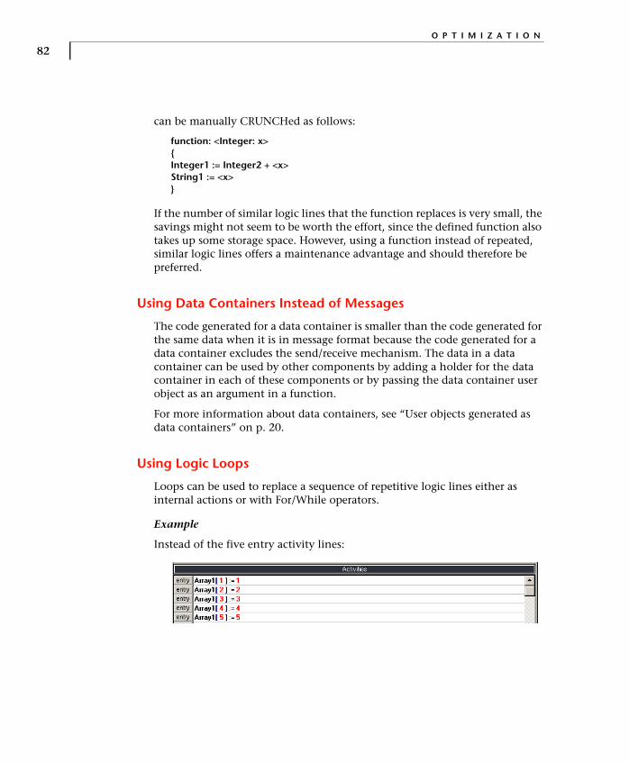
O P T I M I Z A T I O N
82
can be manually CRUNCHed as follows:
function: <Integer: x>{Integer1 := Integer2 + <x>String1 := <x>}
If the number of similar logic lines that the function replaces is very small, the savings might not seem to be worth the effort, since the defined function also takes up some storage space. However, using a function instead of repeated, similar logic lines offers a maintenance advantage and should therefore be preferred.
Using Data Containers Instead of Messages
The code generated for a data container is smaller than the code generated for the same data when it is in message format because the code generated for a data container excludes the send/receive mechanism. The data in a data container can be used by other components by adding a holder for the data container in each of these components or by passing the data container user object as an argument in a function.
For more information about data containers, see “User objects generated as data containers” on p. 20.
Using Logic Loops
Loops can be used to replace a sequence of repetitive logic lines either as internal actions or with For/While operators.
Example
Instead of the five entry activity lines:
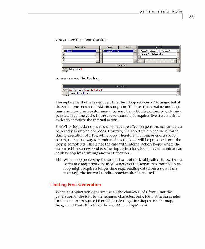
O P T I M I Z I N G R O M
83
you can use the internal action:
or you can use the For loop:
The replacement of repeated logic lines by a loop reduces ROM usage, but at the same time increases RAM consumption. The use of internal action loops may also slow down performance, because the action is performed only once per state machine cycle. In the above example, it requires five state machine cycles to complete the internal action.
For/While loops do not have such an adverse effect on performance, and are a better way to implement loops. However, the Rapid state machine is frozen during execution of a For/While loop. Therefore, if a long or endless loop occurs, there is no way to terminate it as the logic will be processed until the loop is completed. This is not the case with internal action loops, where the state machine can respond to other inputs in a long loop or even terminate an endless loop by activating another transition.
TIP: When loop processing is short and cannot noticeably affect the system, a For/While loop should be used. Whenever the activities performed in the loop might require a longer time (e.g., reading data from a slow Flash memory), the internal condition/action should be used.
Limiting Font Generation
When an application does not use all the characters of a font, limit the generation of the font to the required characters only. For instructions, refer to the section “Advanced Font Object Settings” in Chapter 10: “Bitmap, Image, and Font Objects” of the User Manual Supplement.

O P T I M I Z A T I O N
84
OPTIMIZING PERFORMANCE
Performance is mainly affected by the number of state machine cycles required to perform a given action and the number of operations performed in every cycle. Performance optimization therefore focuses on ways to reduce the number and content of state machine cycles and so improve response time. As a rule, reducing the number of objects, use of primitive rather than Rapid objects, and use of data containers instead of messages, all speed up the application’s initialization processes.
Modifying Logic
Using an If...else action
Replace multiple internal actions that are triggered by an event and condition combination with a single event and an IF...else action.
Example
Replace:
with:
This replacement reduces the number of triggers to be evaluated by the state machine when the event occurs.
Using a For/While loop
Replace internal loops by For/While loops which are completed in a single cycle of the state machine.

O P T I M I Z I N G P E R F O R M A N C E
85
Example
Instead of:
use:
Clearing Holders when not Required
Clearing a holder when the held object is not required, even though its parent is idle, may improve performance when there are dependencies on the held object in other components.
Example
A phone book component has a holder for an editor component, which has a holder for a keypad component. Whenever the keypad component generates an event or changes a property, Rapid checks whether a response is required in the editor holder of the phone book component—even if the phone book component is in idle mode.
This check is very short but, when it happens many times, the accumulated effect may slow performance. Clearing the editor holder in the phone book component eliminates the check by deleting the reference to the editor and so cancelling its keypad dependency.

O P T I M I Z A T I O N
86
Decreasing the Number of State Machine Checks
Replacing an event and property combination by multiple events improves performance by eliminating state machine checking of the property value. For example, in a keypad user object, use a separate event for each function key instead of a general key press event that is accompanied by a keycode property.
However, for the alphanumeric keys, it is more efficient to use an exported event and property combination, as we did in the Ref_Design application.
Replacing Synchronous by Asynchronous Function Calls
A function call in the embedded system may take considerably longer than the simulation of such a call in the Rapid embedded interface component (UDI). When a synchronic function call is used, Rapid manages the retrieval of the requested data, and the state machine stands still until this data is received. When using an asynchronous function, Rapid delegates data retrieval to another task and is therefore free to continue its processing. The Rapid task must be notified when the requested data becomes available.
Decreasing Component Nesting
Each transition of information by a property or message from one level of the nesting hierarchy to the next requires an additional state machine cycle. To reduce the number of required state machine cycles, keep the number of nesting levels to a minimum.
Decreasing Event Chaining
When one event generates another, which in turn produces yet another event and so on, each link in the series of events requires an additional cycle of the state machine. This is true across components as well as within a single component. For better performance, you should avoid such event chaining.
Limiting the Number of Consecutive State Machine Cycles
At the end of each cycle, the state machine returns a “More To Do” value. For detailed information, refer to the section “The State Machine and the ‘More To Do’ Return Value” in Chapter 4: “The Application Programming Interface (API)” of the Generating Code manual.
Typically, the state machine needs about five cycles to return a zero “More To Do” value. When a much larger number of cycles is required to return a zero,

O P T I M I Z I N G P E R F O R M A N C E
87
this indicates a problem in the application and should be investigated during the integration phase.
As long as the “More To Do” value is not zero, the state machine will continue to demand CPU resources. It is the responsibility of the system integrator to call the runRapidCycles function according to task priority and CPU availability. In that function, the maxCycles parameter is used to limit the number of consecutive state machine cycles.
The following excerpt shows the relevant code excerpt from the file App_Api.c:
/*================================================================\| Function: runRapidCycles || Running Rapid state machine cycles to get to the next state || Reacting to all the external inputs and performing all the || entailed activities || Including the internal events generated by the state machine || during the state change |
\==========================================================/int runRapidCycles(int maxCycles){
int rpd_moreToDo, i=0;do{
rpd_moreToDo = rpd_PrivRunIdle();}while(rpd_moreToDo && i++<maxCycles);return rpd_moreToDo;
}
The system integrator should set the value of maxCycles to ensure proper operation of Rapid within the smallest possible number of consecutive state machine cycles. For example, in an application that uses an internal event to display a 10-item list, setting the maxCycle value to 8 will result in a display of the first eight items only. In order to display the last two items, you should call runRapidCycles when the timer update function is called (rpd_PrivUpdateTimer).
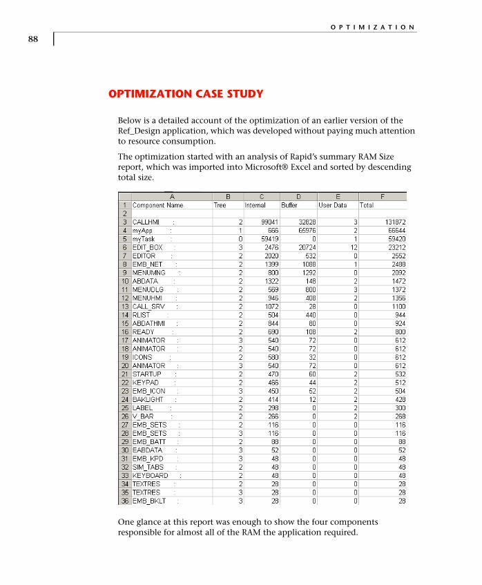
O P T I M I Z A T I O N
88
OPTIMIZATION CASE STUDY
Below is a detailed account of the optimization of an earlier version of the Ref_Design application, which was developed without paying much attention to resource consumption.
The optimization started with an analysis of Rapid’s summary RAM Size report, which was imported into Microsoft® Excel and sorted by descending total size.
One glance at this report was enough to show the four components responsible for almost all of the RAM the application required.

O P T I M I Z A T I O N C A S E S T U D Y
89
The next step was to obtain detailed RAM Size reports for these four components. The detailed report for CALLHMI shows that four string objects account for almost all the RAM this component requires.
In addition, these four strings share almost the same size, which suggests a common default setting. And indeed, this is the Rapid default string size for code generation (Code Generation Preferences dialog box, Data sizes tab). Changing the size of each of these strings to 32 bytes reduced the size of the component by almost 131,000 bytes.

O P T I M I Z A T I O N
90
We next analyzed the myApp component which is called MAINAPP in the detailed report. Because of the large number of objects in this component, we again imported the report into Microsoft® Excel and sorted it by descending object size.
The following illustration is the top part of the sorted detailed report for MAINAPP.
A quick look at the report showed that two objects required most of the RAM, both of them dynamic buffer objects. One was the dynamic buffer of the menu application module (DB_R6588_MENUHMI1). The fact that this buffer is allocated in the main application and not in the MENUHMI component indicates that it is allocated for an interface element and not for an internal object.
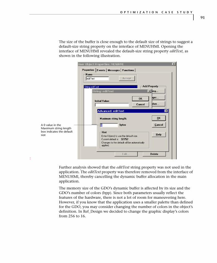
O P T I M I Z A T I O N C A S E S T U D Y
91
The size of the buffer is close enough to the default size of strings to suggest a default-size string property on the interface of MENUHMI. Opening the interface of MENUHMI revealed the default-size string property editText, as shown in the following illustration.
:
Further analysis showed that the editText string property was not used in the application. The editText property was therefore removed from the interface of MENUHMI, thereby cancelling the dynamic buffer allocation in the main application.
The memory size of the GDO’s dynamic buffer is affected by its size and the GDO’s number of colors (bpp). Since both parameters usually reflect the features of the hardware, there is not a lot of room for maneuvering here. However, if you know that the application uses a smaller palette than defined for the GDO, you may consider changing the number of colors in the object’s definition. In Ref_Design we decided to change the graphic display’s colors from 256 to 16.
A 0 value in the Maximum string length box indicates the default size

O P T I M I Z A T I O N
92
Techniques Applied to Reduce RAM Size
After reducing the sizes of the major RAM-consuming components, we applied additional RAM-saving techniques:
• Adjusting object sizes to reflect application needs.
• Combining several instances of a component into one.
• Replacing all timer objects by timer tick objects.
• Removing non-essential buffers.
• Replacing components with very little logic by main application modes.
In comparison with the previous savings, the contribution of the last four techniques was relatively minor, yet it is not to be slighted.
Adjusting object sizes to reflect application needs
Using the RAM Size report, all large-sized arrays and strings were examined against the actual requirements of the application. In all cases where the actual sizes required by the application were smaller than the sizes defined for the objects, the objects were resized.
Combining several instances of a component into one
A closer look at the summary report reveals the presence of three instances of the ANIMATOR component.
Originally the arrays of animation bitmaps resided in three different components. The ANIMATOR component has an exported start function which uses the animation bitmap array as an argument. At present (to be improved in the next version of Rapid), an array argument can be used from the parent application but not from sibling components. Therefore, each of the three components with the animation bitmap arrays had to have its own child ANIMATOR.
In order to combine the three ANIMATOR instances into a single one, the animation bitmap arrays were moved from their original components into the ANIMATOR component. It then became possible to replace the array argument in the ANIMATOR’s start function by an index to the respective array. A single ANIMATOR component could now handle all the animation needs of the application.

O P T I M I Z A T I O N C A S E S T U D Y
93
Replacing all timer objects with timer tick objects
After verifying that none of the application’s timer objects used the count or initialCount properties, all timer objects were replaced by the leaner timer tick objects.
Removing non-essential buffers
Two application components were defined with their own buffers: EDIT_BOX and RLIST. Both of these buffers were eliminated and the logic accordingly adjusted by drawing directly on the GDO.
Replacing components by main application modes
The components READY, STARTUP, and BACKLITE were eliminated and replaced by modes in the main application. These components were selected because they had only the most basic logic and were created mainly to keep the main application’s mode tree uncluttered.
Techniques Applied to Reduce ROM Size
We applied two ROM-reducing techniques:
• Limiting font generation to required characters.
• Cropping bitmaps.
Limiting font generation to required characters
Basically, the use of the font in the application is limited to the characters available on the phone’s keypad. Characters that are not used in the application were excluded from generation.
Cropping bitmaps
The backgrounds of the bitmaps in the ANIMATOR component were cropped to reduce their ROM requirements. Note that the manipulation of bitmap sizes required an adjustment of their positioning on the display.

O P T I M I Z A T I O N
94
Case Study Optimization Summary
The following tables summarize the RAM and ROM savings achieved by the optimizations performed in the case study:
O P T I M I Z A T I O N D E S C R I P T I O N B E F O R E A F T E RS A V E D
R A M
Replacing default sizes in strings 304 KB 173 KB 131 KB
Removing unused default-size string interface element
173 KB 141 KB 32 KB
Reducing GDO colors from 256 to 16 141 KB 125 KB 16 KB
Adjusting object sizes to reflect application needs
125 KB 41 KB 84 KB
Combining several instances of ANIMATOR into one
41 KB 40 KB 1 KB
Replacing timer objects with timer tick objects
40 KB 39 KB 1 KB
Removing non-essential buffers 39 KB 28 KB 11 KB
Replacing components by modes 28 KB 27 KB 1 KB
Total 277 KB
O P T I M I Z A T I O N D E S C R I P T I O N B E F O R E A F T E RS A V E D
R O M
Limiting font generation to required characters
260 KB 243 KB 17 KB
Cropping bitmaps 243 KB 193 KB 50 KB
Total 67 KB

95
A P P E N D I X D
Memory ConsumptionAll sizes shown in the table are in bytes and relate to elements compiled for the 32-bit ARM compiler.
E L E M E N T R A M R O M
R A P I D C O D E D A T A
Baseline application (no objects or logic)
660
The absolute ROM sizes are compiler- and CPU-dependent.
Baseline application with one user object, where the user object has no objects, logic, or interface
896
Baseline application with one user object generated as interface only (no interface)
692
Rapid integer 20 per object 44 per object 40 per object
Primitive integer 4 per object 12 per object 4 per object
Integer array 72 per array + 4 per element
48 per array 64 per array
Message1 (buffer) with integer fields
20 per message + 4 per field
56 per message 12 per message
Message (pointer) with integer fields
20 per message + 0 per field
~325 per message 12 per message

M E M O R Y C O N S U M P T I O N
96
Integer property on user object generated as full object
28 for the first property24 for each subsequent property
~40 per property 28 per property
Integer property on user object generated as interface only
Same as above ~55 per property 28 per property
Event property on user object generated as full object
0 per property 0 0
Event property on user object generated as interface only
Same as above 0 0
Rapid number 20 per object 44 per object 40 per object
Rapid string 28 per object + 1 per character
68 per object 40 per object
Primitive string 1 per character 34 per object 12 per object
Event object 28 per object 40 per object 20 per object
First timer object2 10036 per object 52 per object
Subsequent timer objects 116 per object
First timer tick object2 5628 per object 24 per object
Subsequent timer objects 72 per object
Mode 2 per mode 0 ~16 per mode
Transition 0 0 0 for the first transition, 4 for each subsequent transition
1. A message = a union with one structure.2. The RAM for the first object is somewhat less because it uses an already existing (but empty) first
entry in the required table.
E L E M E N T R A M R O M
R A P I D C O D E D A T A


