Page 1
East Tennessee State UniversityDigital Commons @ East
Tennessee State University
Electronic Theses and Dissertations Student Works
8-2015
Methodology Study of N-deacetylation of4-acetamido-perfluoroalkylbenzenesulfonimideGrace AbbanEast Tennessee State University
Follow this and additional works at: https://dc.etsu.edu/etd
Part of the Chemistry Commons
This Thesis - Open Access is brought to you for free and open access by the Student Works at Digital Commons @ East Tennessee State University. Ithas been accepted for inclusion in Electronic Theses and Dissertations by an authorized administrator of Digital Commons @ East Tennessee StateUniversity. For more information, please contact [email protected] .
Recommended CitationAbban, Grace, "Methodology Study of N-deacetylation of 4-acetamido-perfluoroalkylbenzenesulfonimide" (2015). Electronic Thesesand Dissertations. Paper 2553. https://dc.etsu.edu/etd/2553
Page 2
Methodology Study of N-deacetylation of 4-acetamido-perfluoroalkylbenzenesulfonimide
________________________
A thesis
presented to
the faculty of the Department of Chemistry
East Tennessee State University
In partial fulfilment
of the requirements for the
Master of Science in Chemistry
________________________
by
Grace Abban
August 2015
________________________
Dr. Hua Mei, Chair
Dr. Peter Zhao
Dr. Abbas G. Shilabin
Keywords: N-deacetylation, perfluoroalkyl benzenesulfonylimide (PFSI) monomer
Page 3
2
ABSTRACT
Methodology Study of N-deacetylation of 4-acetamido-perfluoroalkylbenzenesulfonimide
by
Grace Abban
In order to improve the synthetic route for diazonium perfluoroalkyl benzenesulfonylimide
(PFSI) zwitterionic monomers, N-deacetylation of the coupling product was proposed to replace
the reduction of aromatic amine intermediates. A series of hydrolysis methods, such as acid and
base catalyzed refluxing, were explored for the N-deacetylation to obtain the PFSI aromatic
amine. Factors such as temperature, concentration of acid/base and the time needed for the
reaction to take place were investigated in an attempt to optimize the reaction condition. The
basic hydrolysis was preferred since it was expected to carry out the N-deacetylation and
debromination in one batch reaction. N-deacetylation in base at high concentrations was
successful, however, side reaction of the perfluorovinyl ether occurred. It was discovered that the
best N-deacetylation method is to reflux/sonicate the coupling product with acid in methanol for
six hours. The intermediates and purified products were characterized with 1HNMR, 19FNMR,
GC-MS and IR.
Page 4
3
DEDICATION
This work is dedicated to the Almighty God for his protection and guidance, my father
Mr. Joseph Abban, my mother madam Anastasia Donkoh and my siblings.
Page 5
4
ACKNOWLEDGEMENTS
Thanks to God Almighty for his protection, care, abundant grace and mercy that has seen
me through my course successfully. My sincere gratitude goes to my advisor Dr. Hua Mei for her
guidance and encouragement throughout this research work, I say God richly bless you.
Thanks to Dr. Zhao and Dr. Shilabin for serving as committee members and also Dr.
Mohseni for his assistance with the instruments. Thanks to Mr. John Sierra and Mr. and Mrs.
Van-Dyck for their support and advice.
Special thanks to my friends Abdulmajeed Alayyaf, Faisal Ibrahim, Selorm Joy Fanah
and Isaac Addo and, for helping me in diverse ways.
Finally, I would like to say a big thank you to the ETSU faculty, staff, and graduate
students of the Chemistry Department for their utmost assistance and support throughout my
time here.
Page 6
5
TABLE OF CONTENTS
Page
ABSTRACT ………………………………………………………………………………………2
DEDICATION ……………………………………………………………………………………3
ACKNOWLEDGEMENTS ……..………………………………………………………………..4
LIST OF FIGURES ……………………………………………………………………………....8
LIST OF SCHEMES …………………………………………………………………………......9
LIST OF ABBREVIATIONS …………………………………………………………………...10
Chapter
1. INTRODUCTION ……………………………………………………………………....11
Preface ……………………………………………………………………………….......11
N-deacetylation …………………………………………………………………….........11
Fuel Cells ……………………………………………………………………………......17
Diazonium PFSI Zwitterionic Monomers……………………………………………......20
2. RESEARCH AND DISCUSSION …………………………………………………….. 25
Ammonolysis Reaction of 4-Sulfamonylacetanilide ………………………...………….25
Bromination of Nafion® Monomer ……………………………………………………...26
Coupling Reaction …………………………………………………………………........26
N-deacetylation of the Coupling Product ……………………………………………….28
3. EXPERIMENTAL …………………………………………………………………..…..35
General Considerations ………...……………………………………………………......35
Page 7
6
Chapter Page
NMR Spectroscopy ………………………………………………………….......35
Gas Chromatography-Mass Spectrometer ……………………………………....35
Infra-Red Spectroscopy ..………………………………………………………..35
Glass Vacuum System …………………………………………………………..36
Thin Layer Chromatography ………………………………………………........36
Purification of Solvents and Experimental Practice …………………………….36
Synthesis of 4-sulfamonylacetanilide ……………………………………………….......37
Synthesis of FSO2CF2CF2OCF(CF3)CF2OCFBrCF2Br …………………………............37
Synthesis of CH3CONHPhSO2N(M)SO2CF2CF2OCF(CF3)CF2OCFBrCF2Br …............38
Synthesis of NH2PhSO2N(M)SO2CF2CF2OCF(CF3)CF2OCFBrCF2Br …………...……39
Synthesis of NH2PhSO2N(M)SO2CF2CF2OCF(CF3)CF2OCF=CF2 ...……………...…...40
4. CONCLUSION ………………………………………………………………………….41
REFERENCES ………………………………………………………………………….......43
APPENDICES …………………………………………………………………………...….47
Appendix A: GC-MS Chromatogram of Compound 2 ………………………………….47
Appendix B1: 19F NMR Spectrum of Compound 3, 400MHz, Acetone-d6 …...……......48
Appendix B2: 19F NMR Spectrum of Compound 4, 400MHz, CD3CN …………...........49
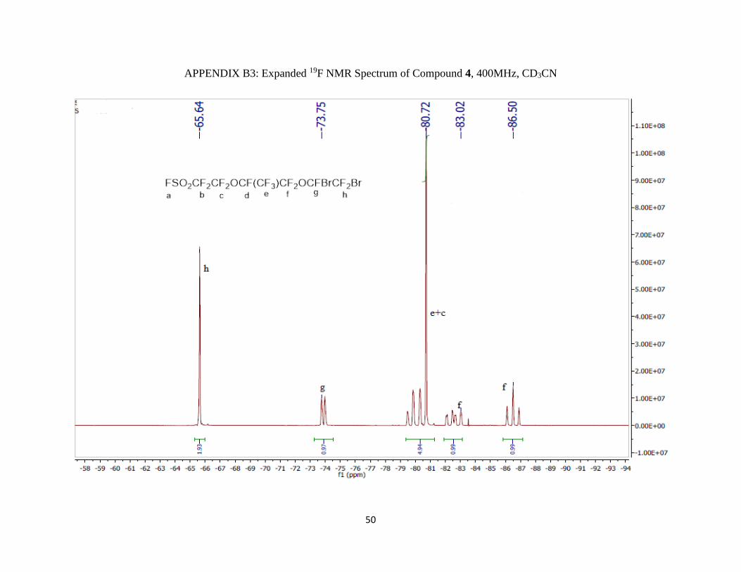
Appendix B3: Expanded 19F NMR Spectrum of Compound 4, 400MHz, CD3CN ……..50
Appendix B4: 19F NMR Spectrum of Compound 5, 400MHz, CD3CN …………….......51
Page 8
7
Chapter Page
Appendix B5: 19F NMR Spectrum of Compound 6, 400MHz, CD3CN …………….......52
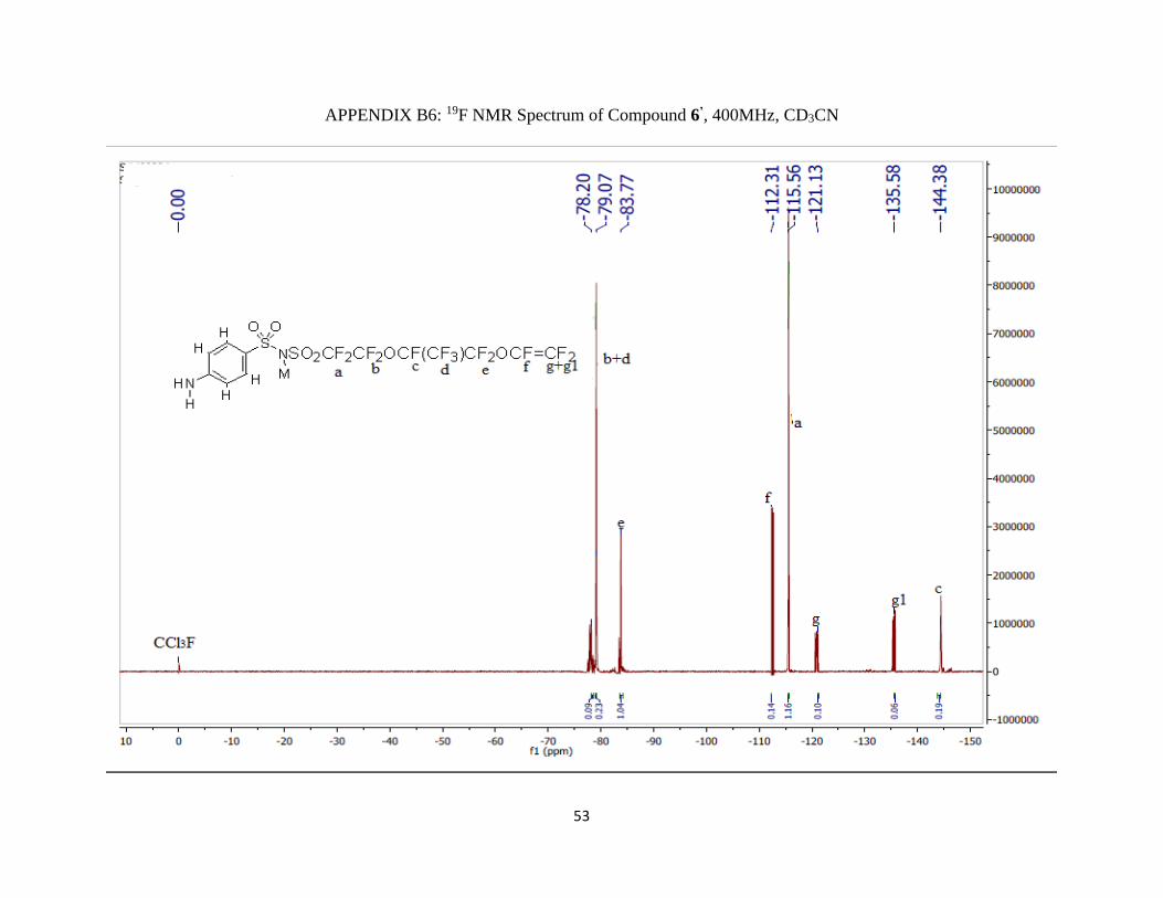
Appendix B6: 19F NMR Spectrum of Compound 6’, 400MHz, CD3CN ……………......53
Appendix B7: 19F NMR Spectrum of Basic Hydrolysis Byproduct, 400MHz, CD3CN ..54
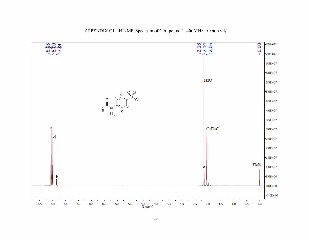
Appendix C1: 1H NMR Spectrum of Compound 1, 400MHz, Acetone-d6 ………..........55
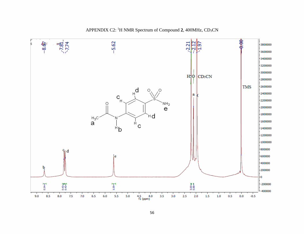
Appendix C2: 1H NMR Spectrum of Compound 2, 400MHz, CD3CN …………............56
Appendix C3: Expanded 1H NMR Spectrum of Compound 2, 400MHz, CD3CN ….......57
Appendix C4: 1H NMR Spectrum of Compound 5, 400MHz, CD3CN ………………....58
Appendix C5: Expanded 1H NMR Spectrum of Compound 5, 400MHz, CD3CN ….......59
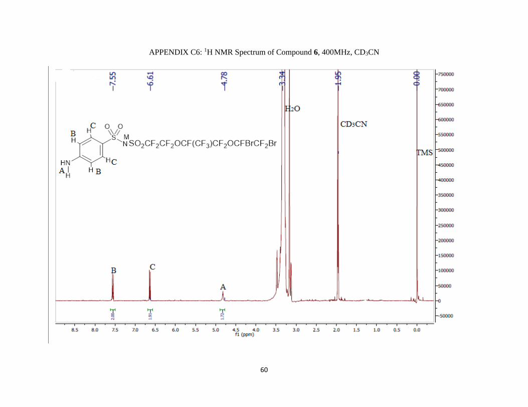
Appendix C6: 1H NMR Spectrum of Compound 6, 400MHz, CD3CN ………………....60
Appendix C7: Expanded 1H NMR Spectrum of Compound 6, 400MHz, CD3CN…........61
Appendix D1: FT-IR Spectrum of Compound 1 ...………………………..………….....62
Appendix D2: FT-IR Spectrum of Compound 2………………..…………………….....63
Appendix D3: FT-IR Spectrum of Compound 5 …………………..…………...…….....64
Appendix D4: FT-IR Spectrum of Compound 6………………..………………….…....65
VITA …………………………………………………………………………………….…..66
Page 9
8
LIST OF FIGURES
Figure Page
1. The structure of the leaving group……….…………………………………………………....12
2. The structure of the PEM fuel cell (modified from Thampan)………………………..………19
3. The possible hydrolysis by-product from the coupling reaction …………….…………….....27
4. The structure of the protonated amide tetrahedral adduct …………………………….……...33
5. The structure of the debrominated product …………………………..……………….............34
6. The line diagram of the dual-manifolds glass vacuum line. Used with permission …….....…36
Page 10
9
LIST OF SCHEMES
Scheme Page
1. The resonance structure of the PFSI monomer………………….……………………….........12
2. An example of an acid catalyzed amide hydrolysis…………………………………………...13
3. The mechanism for the acid catalyzed N-deacetylation ………………………………….......14
4. The base catalyzed hydrolysis mechanism …………………………………….…………......16
5. The reactions occurring in a PEM fuel cell...…………….……………………………….......19
6. An example of an amino acid zwitterion .….….………….………….……………………….20
7. The grafting of the FDZ on the carbon electrode..…………………………………………....21
8. The previously published overall synthesis scheme…..……………………………………....22
9. The proposed synthesis scheme ..………..………………………………………………........23
10. The ammonolysis reaction of N-acetyl sulfanilyl chloride ……………………………….....25
11. The bromination reaction of Nafion® monomer ………………….……………………........26
12. The coupling reaction of 4-sulfamonylacetanilide with brominated Nafion® monomer ........27
13. The N-deacetylation reaction of the coupling product ………………………………............32
Page 11
10
LIST OF ABBREVATIONS
AFC Alkaline Fuel Cell
DIEA Diisopropyl Ethyl Amine
DIEAH+ Diisopropyl Ethyl Amine Salt
DMFC Direct Methanol Fuel Cell
FDZ Functional Diazonium Zwitterion
FT-IR Fourier Transform Infra-Red
GC-MS Gas Chromatography-Mass Spectrometry
Hz Hertz
MCFC Molten Carbonate Fuel Cell
MEA Membrane Electrode Assembly
NMR Nuclear Magnetic Resonance
PAFC Phosphoric Acid Fuel Cell
PEMFC Polymer Electrolyte Membrane Fuel Cell
PFSA Perflurosulfonic acid
PFSI Perflurosulfonylimide
ppm Parts per million
SOFC Solid Oxide Fuel Cell
TMS Tetramethylsilane
TLC Thin Layer Chromatography
UV Ultra Violet
Page 12
11
CHAPTER 1
INTRODUCTION
Preface
This research was aimed at the methodological study of n-deacetylation of 4-acetamido-
perfluoroalkylbenzenesulfonimide to replace the reduction of nitroaromatics in the synthetic
route of diazonium perfluoroalkyl benzene sulfonimide (PFSI) zwitterionic monomers for use in
proton exchange membrane (PEM) fuel cells after polymerization.
Background for this project, along with the motivation of this research work, is given in
the introduction. The details about this methodological study, as well as the characterization of
both the intermediates and products, are discussed in the subsequent chapters. N-deacetylation is
presented first, followed by a short overview of fuel cells, and finally an overview of the recently
synthesized diazonium PFSI zwitterionic monomers. The use of acetamide was expected to
expedite both the ammonolysis and coupling reactions. Also, the inorganic impurity associated
with the aromatic reduction can be avoided with the new method.
N-deacetylation
N-deacetylation, also known as the hydrolysis of amides, is a nucleophilic acyl
substitution reaction which occurs via an addition-elimination mechanism.1 It is a very effective
synthesis method to produce amines.2 For organic synthesis design, amines are often protected
since they are very active groups, which are prone to be further oxidized, or undergo
electrophilic aromatic substitution.3 The main factors that affect the reactivity of amide
hydrolysis include: 1) resonance stability, 2) leaving group ability and 3) steric effect.4
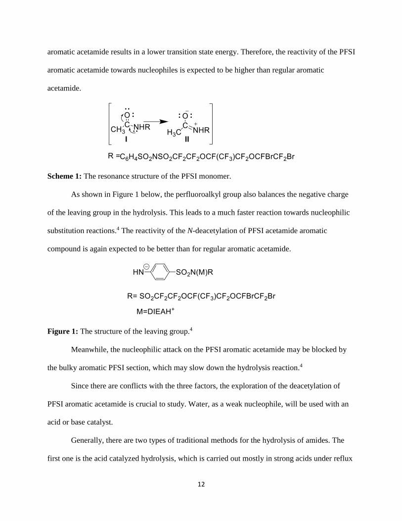
The resonance structure (II in Scheme 1) of the PFSI aromatic acetamide is destabilized
by the electron-withdrawing perfluoroalkyl chain. The loss of the resonance stability of the PFSI
Page 13
12
aromatic acetamide results in a lower transition state energy. Therefore, the reactivity of the PFSI
aromatic acetamide towards nucleophiles is expected to be higher than regular aromatic
acetamide.
Scheme 1: The resonance structure of the PFSI monomer.
As shown in Figure 1 below, the perfluoroalkyl group also balances the negative charge
of the leaving group in the hydrolysis. This leads to a much faster reaction towards nucleophilic
substitution reactions.4 The reactivity of the N-deacetylation of PFSI acetamide aromatic
compound is again expected to be better than for regular aromatic acetamide.
Figure 1: The structure of the leaving group.4
Meanwhile, the nucleophilic attack on the PFSI aromatic acetamide may be blocked by
the bulky aromatic PFSI section, which may slow down the hydrolysis reaction.4
Since there are conflicts with the three factors, the exploration of the deacetylation of
PFSI aromatic acetamide is crucial to study. Water, as a weak nucleophile, will be used with an
acid or base catalyst.
Generally, there are two types of traditional methods for the hydrolysis of amides. The
first one is the acid catalyzed hydrolysis, which is carried out mostly in strong acids under reflux
Page 14
13
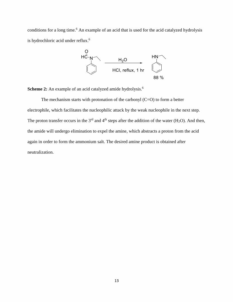
conditions for a long time.6 An example of an acid that is used for the acid catalyzed hydrolysis
is hydrochloric acid under reflux.6
Scheme 2: An example of an acid catalyzed amide hydrolysis.6
The mechanism starts with protonation of the carbonyl (C=O) to form a better
electrophile, which facilitates the nucleophilic attack by the weak nucleophile in the next step.
The proton transfer occurs in the 3rd and 4th steps after the addition of the water (H2O). And then,
the amide will undergo elimination to expel the amine, which abstracts a proton from the acid
again in order to form the ammonium salt. The desired amine product is obtained after
neutralization.
Page 15
14
Scheme 3: The mechanism for the acid catalyzed N-deacetylation.
Usually the catalysts used for the acid hydrolysis are strong mineral acids, Lewis acids or
Brᴓnsted acids under reflux conditions. Recently, examples of methods studied for the acid
hydrolysis catalysts include: H2 and MeSO3H in THF under autoclave,6 Hydrozirconocene Cl in
THF7 at room temperature, SOCl2 in MeOH,9 and AlCl3 11 under microwave irradiation. These
methods were used to prepare primary, 6 secondary and tertiary amines such as N-butylamine, N-
Page 16
15
ethylaniline and tributylamine respectively. Also there is no C-N bond cleavage7 from the
hydrolysis of aromatic amides and heteroaromatic amides. The above methods are clean, solvent
free and result in high yields of the desired products.11, 12 Furthermore, there is no observable
epimerization of chiral acetamides associated with these methods.7 However, harsh conditions,
costly catalysts and long reaction times are required to carry out such reactions.13 Moreover,
problems like low chemical selectivities,21 and formation of the corresponding carboxylic acids
or esters10, 22 are associated with some methods.
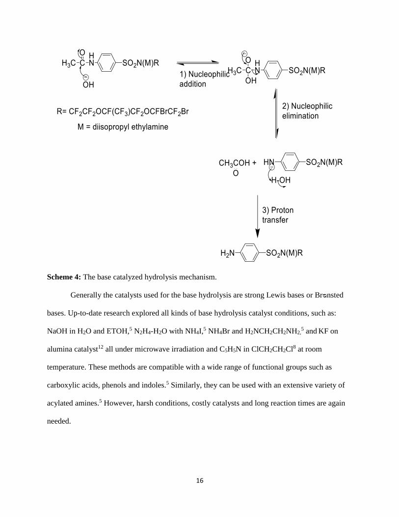
The second type of methods involves reflux with strong base. The base catalyzed
hydrolysis mechanism is different from the acid mainly in the first step. The acid catalyst is
employed to generate a stronger electrophile while the base catalyst converts water into a strong
nucleophile, the hydroxyl anion. The base hydrolysis amide mechanism starts with the
nucleophilic addition of the base, followed by the nucleophilic elimination of the leaving-group
and next the abstraction of a base to form the desired amines as shown in Scheme 4.
Page 17
16
Scheme 4: The base catalyzed hydrolysis mechanism.
Generally the catalysts used for the base hydrolysis are strong Lewis bases or Brᴓnsted
bases. Up-to-date research explored all kinds of base hydrolysis catalyst conditions, such as:
NaOH in H2O and ETOH,5 N2H4-H2O with NH4I,5 NH4Br and H2NCH2CH2NH2,
5 and KF on
alumina catalyst12 all under microwave irradiation and C5H5N in ClCH2CH2Cl8 at room
temperature. These methods are compatible with a wide range of functional groups such as
carboxylic acids, phenols and indoles.5 Similarly, they can be used with an extensive variety of
acylated amines.5 However, harsh conditions, costly catalysts and long reaction times are again
needed.
Page 18
17
Fuel Cells
Fuel cell technologies have received much attention over the years as the means of
providing viable clean energy, due to the growing concerns about the depletion of petroleum
energy resources and climate change. Although hydrogen is the most common fuel,
hydrocarbons such as natural gas and alcohols like methanol are sometimes used for greater
efficiency.14 Fuel cells have the likelihood of replacing the internal combustion engine in
vehicles and other power applications due to their energy-efficient, clean and fuel flexibility
characteristics.16, 19 Fuel cells batteries are different from regular batteries because fuel cells
require a constant source of fuel and oxygen/air to sustain the chemical reaction. Fuel cells can
produce electricity continually for as long as these inputs are supplied. The applications of fuel
cells include power for transportation, portable power generation and stationary power
generation.15 A fuel cell consists of an electrolyte that is enfolded between two electrodes
(cathode and anode) to generate electricity.16 To produce electrical current, the electrons move
from the anode to the cathode through an external circuit.
Table 1:16-18 Comparison of different types of fuel cells.
Fuel Cell Electrolyte Fuel Used Operating
Temperature
Polymer Electrolyte Membrane Fuel
Cell (PEMFC)
H+ conducting
Membrane
H2 ~80 oC
Alkaline Fuel Cell (AFC) KOH H2 ~100 oC
Phosphoric Acid Fuel Cells (PAFC) Concentrated
H3PO4
Natural gas, H2 ~200 oC
Page 19
18
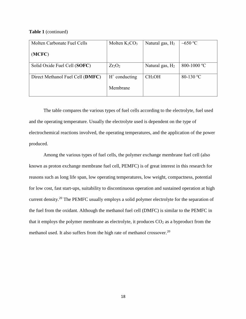
Table 1 (continued)
Molten Carbonate Fuel Cells
(MCFC)
Molten K2CO3 Natural gas, H2 ~650 oC
Solid Oxide Fuel Cell (SOFC) Zr2O2 Natural gas, H2 800-1000 oC
Direct Methanol Fuel Cell (DMFC) H+ conducting
Membrane
CH3OH 80-130 oC
The table compares the various types of fuel cells according to the electrolyte, fuel used
and the operating temperature. Usually the electrolyte used is dependent on the type of
electrochemical reactions involved, the operating temperatures, and the application of the power
produced.
Among the various types of fuel cells, the polymer exchange membrane fuel cell (also
known as proton exchange membrane fuel cell, PEMFC) is of great interest in this research for
reasons such as long life span, low operating temperatures, low weight, compactness, potential
for low cost, fast start-ups, suitability to discontinuous operation and sustained operation at high
current density.20 The PEMFC usually employs a solid polymer electrolyte for the separation of
the fuel from the oxidant. Although the methanol fuel cell (DMFC) is similar to the PEMFC in
that it employs the polymer membrane as electrolyte, it produces CO2 as a byproduct from the
methanol used. It also suffers from the high rate of methanol crossover.20
Page 20
19
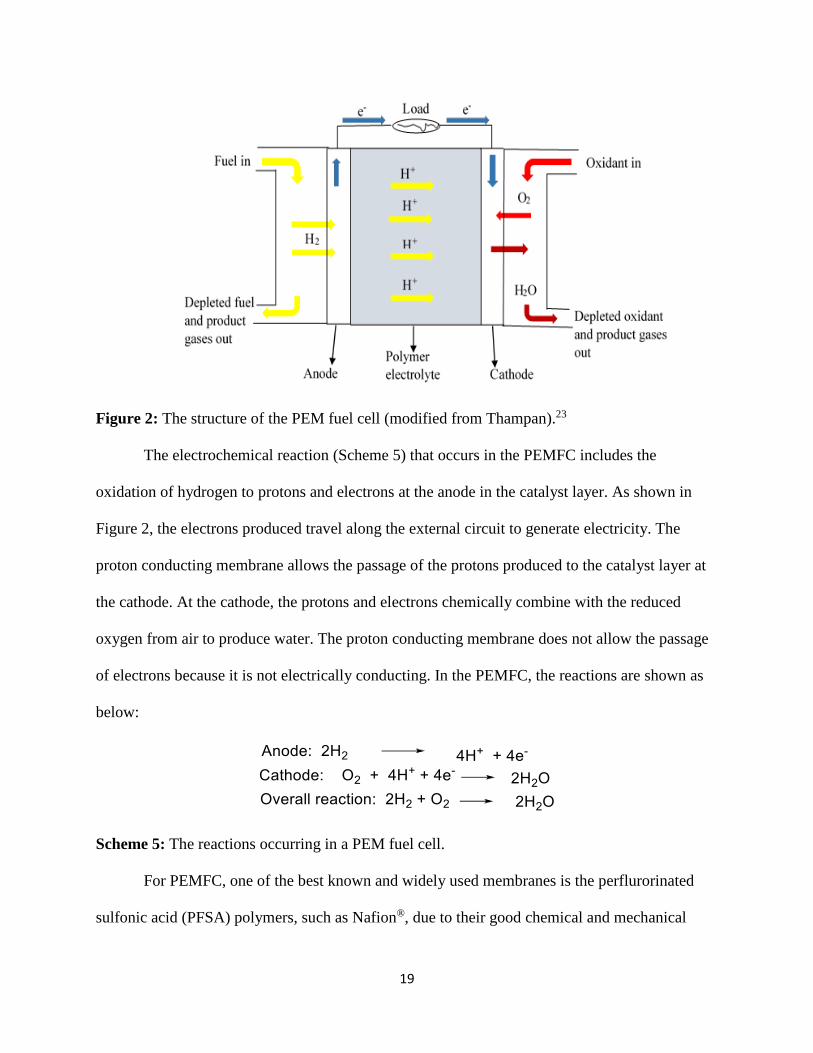
Figure 2: The structure of the PEM fuel cell (modified from Thampan).23
The electrochemical reaction (Scheme 5) that occurs in the PEMFC includes the
oxidation of hydrogen to protons and electrons at the anode in the catalyst layer. As shown in
Figure 2, the electrons produced travel along the external circuit to generate electricity. The
proton conducting membrane allows the passage of the protons produced to the catalyst layer at
the cathode. At the cathode, the protons and electrons chemically combine with the reduced
oxygen from air to produce water. The proton conducting membrane does not allow the passage
of electrons because it is not electrically conducting. In the PEMFC, the reactions are shown as
below:
Scheme 5: The reactions occurring in a PEM fuel cell.
For PEMFC, one of the best known and widely used membranes is the perflurorinated
sulfonic acid (PFSA) polymers, such as Nafion®, due to their good chemical and mechanical
Page 21
20
stability at low temperatures.24 However, there are some limitations for PFSA polymers, such as
decreased proton conductivity at higher temperatures, short life span due to the gradual loss of
electrolyte activity, relatively weak electrode-electrolyte bonding, and poor water management.25
Diazonium PFSI Zwitterionic Monomers
In past years, PFSI polymers were proposed to replace the PFSA polymers for the
electrolyte in PEMFC.26 The PFSI polymers are well known to have greater thermal stability in
the acid form, inertness to electrochemical conditions, and lower susceptibility to oxidative
degradation and dehydration compared to PFSA polymers.26 The zwitterionic monomers is
expected to polymerized before or after grafted onto the carbon electrode.
These PFSI zwitterionic monomers are comparable more stable than regular diazonium
compounds. The first reason is that they are zwitterions. Zwitterions are the salts that possesses
substituent groups with the anion and cation contained in the same molecule. A traditional
example of zwitterions is an amino acid containing an ammonium and a carboxylate group at the
iso-electric point. Furthermore, zwitterions are described as semipolar compounds because they
have significant charge separation between the directly bonded atoms. In semipolar groups, a
filled orbital on one atom and an unfilled orbital on the other are inductively distorted by the
charge separation.27 The second reason is that the monomers are quite large with the PFSI
pendant. Small diazonium compounds are generally known as explosive.
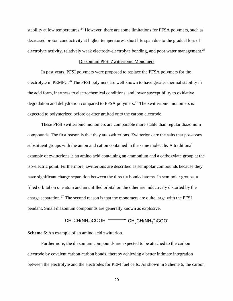
Scheme 6: An example of an amino acid zwitterion.
Furthermore, the diazonium compounds are expected to be attached to the carbon
electrode by covalent carbon-carbon bonds, thereby achieving a better intimate integration
between the electrolyte and the electrodes for PEM fuel cells. As shown in Scheme 6, the carbon
Page 22
21
support is expected to be modified with a functional diazonium zwitterion by losing the
diazonium group -N2+ via thermo or reductive electro-chemcial reaction.28
Scheme 7: The grafting of the FDZ on the carbon electrode (FDZ is a functional diazonium
zwitterion).
Finally, the PFSI monomers can also be copolymerized with tetrafluorovinyl ether to
provide excellent thermal and mechanical stability as electrolytes.30 Therefore the synthesis of
these diazonium PFSI zwitterionic monomers is very crucial for PEM fuel cell technology.
Recently, two forms of these diazonium PFSI monomers have been synthesized. The
synthesis is shown in Scheme 8. The synthesis of these diazonium PFSI monomers involves the
use of Fe/HCl/H2 gas to reduce the nitroaromatics to aminoaromatics (Step 4 in Scheme 8) which
can further be converted to the diazonium. But it is problematic to completely remove the
inorganic impurity, such as an iron chloride complex, from the aminoaromatics after reduction.29
Page 23
22
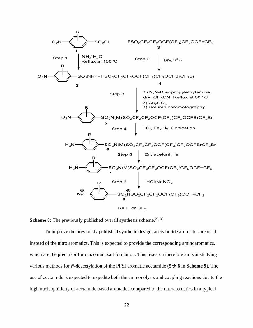
Scheme 8: The previously published overall synthesis scheme.29, 30
To improve the previously published synthetic design, acetylamide aromatics are used
instead of the nitro aromatics. This is expected to provide the corresponding aminoaromatics,
which are the precursor for diazonium salt formation. This research therefore aims at studying
various methods for N-deacetylation of the PFSI aromatic acetamide (5 6 in Scheme 9). The
use of acetamide is expected to expedite both the ammonolysis and coupling reactions due to the
high nucleophilicity of acetamide based aromatics compared to the nitroaromatics in a typical
Page 24
23
SN2 reaction. This method is expected to provide the aminoaromatics with better yield and purity
due to the absence of inorganic impurities such as iron chloride complex which is associated
with the previous synthetic design.
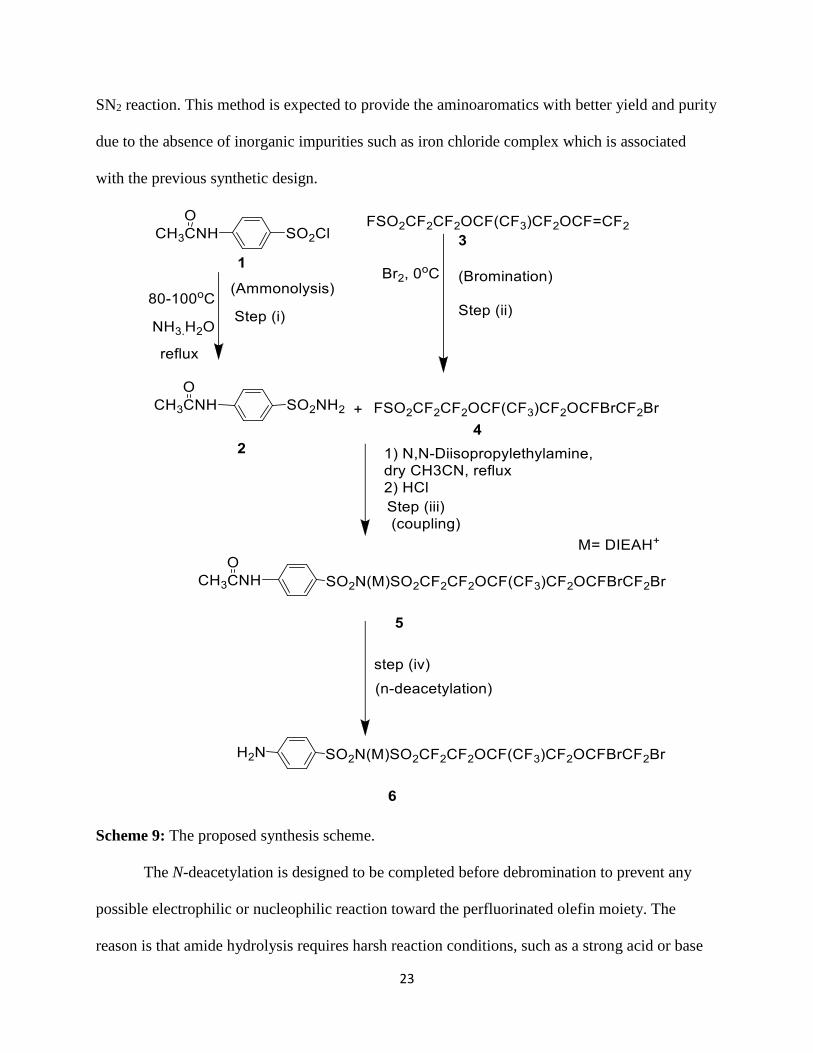
Scheme 9: The proposed synthesis scheme.
The N-deacetylation is designed to be completed before debromination to prevent any
possible electrophilic or nucleophilic reaction toward the perfluorinated olefin moiety. The
reason is that amide hydrolysis requires harsh reaction conditions, such as a strong acid or base
Page 25
24
at high temperature.11 Such harsh reaction conditions limits the N-deacetylation in terms of the
compatibility of perfluorinated olefins. Methods to remove the acyl group from the amide via
general acid under mild conditions were developed in our lab. The purity, reaction time and
percentage yields of the new synthetic route were explored and compared.
Since the debromination of vicinal dibromides of PFSI compounds were successfully
carried out in our lab with base,29 one pot reaction of N-deacetylation and debromination was
under investigation with base catalyst to possibly shorten the previously published overall
synthetic design for the diazonium PFSI monomers.
Page 26
25
CHAPTER 2
RESEARCH AND DISCUSSION
The main focus of this research was the methodological study of the N-deacetylation
reaction of 4-acetamido-perfluoroalkylbenzenesulfonimide to provide 4-amino-
perfluoroakylebenzenesulfonimide, which was the fourth step for the synthesis of diazonium
PFSI monomers. There were three other steps namely; ammonolysis reaction, bromination
reaction and coupling reaction, before the N-deacetylation reaction. The synthesized compounds
were characterized by 1H NMR, 19F NMR, GC-MS and IR spectroscopy.
Ammonolysis Reaction of 4-Sulfamonylacetanilide
The synthesis of 4-sulfamonylacetanilide 2, from N-acetyl sulfanilyl chloride 1, was
carried out by refluxing it in the presence of excess ammonium hydroxide and acetonitrile. The
stoichiometric mole ratio of sulfonyl chloride to aqueous ammonia was 1:2 respectively. This
SN2 reaction, as shown in Scheme 10, involved the replacement of the Cl- ion with the NH2-
group. Next, the unreacted ammonia neutralized the byproduct HCl. The ammonolysis prevailed
over the hydrolysis because NH3 is a better nucleophile than H2O. The “sulfonic acid” formed by
hydrolysis was converted to the water soluble ammonium salt. Pure 4-sulfamonylacetanilide 2
was isolated by vacuum filtration since both the hydrolysis by-product and side-product NH4Cl
are completely soluble in water. A yield of 74 % was obtained.
Scheme 10: The ammonolysis reaction of N-acetyl sulfanilyl chloride (i: Ammonia water 28-
30%, reflux at 100 oC overnight).
Page 27
26
Bromination of Nafion® Monomer
The Nafion® monomer 3 was very sensitive to bases at high temperatures because of its
strong electron withdrawing perfluoroalkyl group. Hence, it was necessary to protect the double
bonds before performing the coupling reaction with base at high temperatures. Protection of the
sensitive double bond was achieved through a free radical reaction with bromine liquid at low
temperature. Purification of the brominated product 4 was successfully done using vacuum
distillation.
Scheme 11: Bromination of Nafion® monomer (ii: Br2, 0 oC to room temperature).
Coupling Reaction
The coupling reaction was done under nitrogen gas protection because the brominated
Nafion® monomer not only reacts with aryl sulfonyl amide at high temperatures but also can be
attacked by weak base catalyzed water to form the hydrolyzed product. The nucleophilicity of
the sulfonyl amide –SO2NH2 is increased when catalyzed by an organic base such as diisopropyl
ethylene amine (DIEA). Compared to the nitro group, the acetamide as a moderate electron
donating group, can further boost the rate of the coupling reaction.
Page 28
27
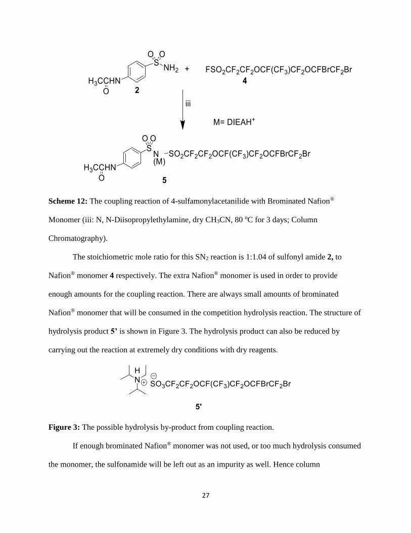
Scheme 12: The coupling reaction of 4-sulfamonylacetanilide with Brominated Nafion®
Monomer (iii: N, N-Diisopropylethylamine, dry CH3CN, 80 oC for 3 days; Column
Chromatography).
The stoichiometric mole ratio for this SN2 reaction is 1:1.04 of sulfonyl amide 2, to
Nafion® monomer 4 respectively. The extra Nafion® monomer is used in order to provide
enough amounts for the coupling reaction. There are always small amounts of brominated
Nafion® monomer that will be consumed in the competition hydrolysis reaction. The structure of
hydrolysis product 5’ is shown in Figure 3. The hydrolysis product can also be reduced by
carrying out the reaction at extremely dry conditions with dry reagents.
Figure 3: The possible hydrolysis by-product from coupling reaction.
If enough brominated Nafion® monomer was not used, or too much hydrolysis consumed
the monomer, the sulfonamide will be left out as an impurity as well. Hence column
Page 29
28
chromatography was run to remove the extra starting materials sulfonamide. Also the crude
coupling product was sticky due to its DIEAH+ counter ion. The DIEAH+ segment was then
converted to acid and removed by solvent extraction. Surprisingly, N-deacetylation occurred at
room temperature during the acidification process. It led to further investigation into the N-
deacetylation of the coupled product 5 under mild conditions.
N-deacetylation of the Coupling Product
N-deacetylation, also called an amide hydrolysis reaction and a nucleophilic acyl
substitution reaction, occurs via an addition-elimination mechanism. Due to the less reactivity of
amides, the hydrolysis usually will be achieved using strong acids or strong bases at high
temperatures according to the literature.4, 31 The unexpected N-deacetylation of PFSI aromatic
acetamide during acidification of the sticky coupling product offers us the opportunity to study
such reactions under mild conditions. Therefore, various reaction conditions were designed and
explored for the N-deacetylation of the coupling product. The reaction conditions are tabulated as
follows in Table 2:
Page 30
29
Table 2: Results for N-deacetylation of the Coupling Product.
Entry N-
Acetamide
(mmol )
Catalyst
Conc.
(mol/L)
Solvent Condition Time
(hrs.)
% Isolated
Yield
% N-
deacetylation
%
debromination
1 0.197 HCl (4.0) 2 mL H2O + 4
mL Acetone
Reflux 24 88.94 100 0
2 0.197 HCl (4.0) 2 mL H2O + 4
mL Acetone
Sonication 6 91.65 87.33 0
3 0.197 HCl (4.0) 2 mL H2O + 4
mL Acetone
Room
temperature
144 83.52 100 0
4 0.197 HCl (3.0) 3 mL H2O + 4
mL Acetone
Reflux 48 91.70 0 0
5 0.197 CH3COOH
(7.0)
6 mL H2O + 4
mL Acetone
Sonication 48 81.92 0 0
6 0.197 CH3COOH
(7.0)
6 mL H2O + 4
mL Acetone
Reflux 48 82.80 0 0
Page 31
30
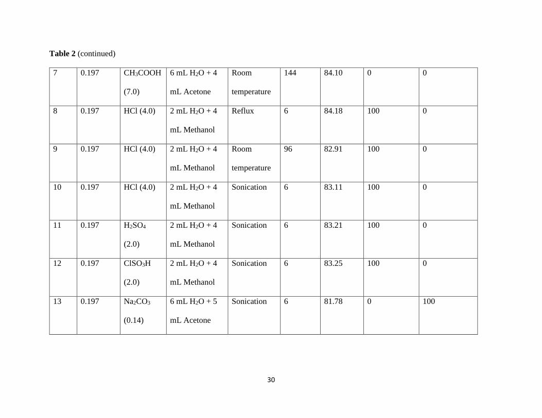
Table 2 (continued)
7 0.197 CH3COOH
(7.0)
6 mL H2O + 4
mL Acetone
Room
temperature
144 84.10 0 0
8 0.197 HCl (4.0) 2 mL H2O + 4
mL Methanol
Reflux 6 84.18 100 0
9 0.197 HCl (4.0) 2 mL H2O + 4
mL Methanol
Room
temperature
96 82.91 100 0
10 0.197 HCl (4.0) 2 mL H2O + 4
mL Methanol
Sonication 6 83.11 100 0
11 0.197 H2SO4
(2.0)
2 mL H2O + 4
mL Methanol
Sonication 6 83.21 100 0
12 0.197 ClSO3H
(2.0)
2 mL H2O + 4
mL Methanol
Sonication 6 83.25 100 0
13 0.197 Na2CO3
(0.14)
6 mL H2O + 5
mL Acetone
Sonication 6 81.78 0 100
Page 32
31
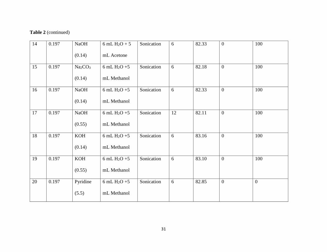
Table 2 (continued)
14 0.197 NaOH
(0.14)
6 mL H2O + 5
mL Acetone
Sonication 6 82.33 0 100
15 0.197 Na2CO3
(0.14)
6 mL H2O +5
mL Methanol
Sonication 6 82.18 0 100
16 0.197 NaOH
(0.14)
6 mL H2O +5
mL Methanol
Sonication 6 82.33 0 100
17 0.197 NaOH
(0.55)
6 mL H2O +5
mL Methanol
Sonication 12 82.11 0 100
18 0.197 KOH
(0.14)
6 mL H2O +5
mL Methanol
Sonication 6 83.16 0 100
19 0.197 KOH
(0.55)
6 mL H2O +5
mL Methanol
Sonication 6 83.10 0 100
20 0.197 Pyridine
(5.5)
6 mL H2O +5
mL Methanol
Sonication 6 82.85 0 0
Page 33
32
Table 2 (continued)
21 0.197 NaOH
(1.64)
6 mL H2O +5
mL Methanol
Sonication 0.5 83.25 0 0
22 0.197 NaOH
(3.27)
6 mL H2O +5
mL Methanol
Sonication 0.5 83.28 100 0
23 0.197 NaOH
(6.55)
6 mL H2O +5
mL Methanol
Sonication 0.5 83.12 100 0
Scheme 13: The N-deacetylation reaction of the coupling product. (step iv).
Page 34
33
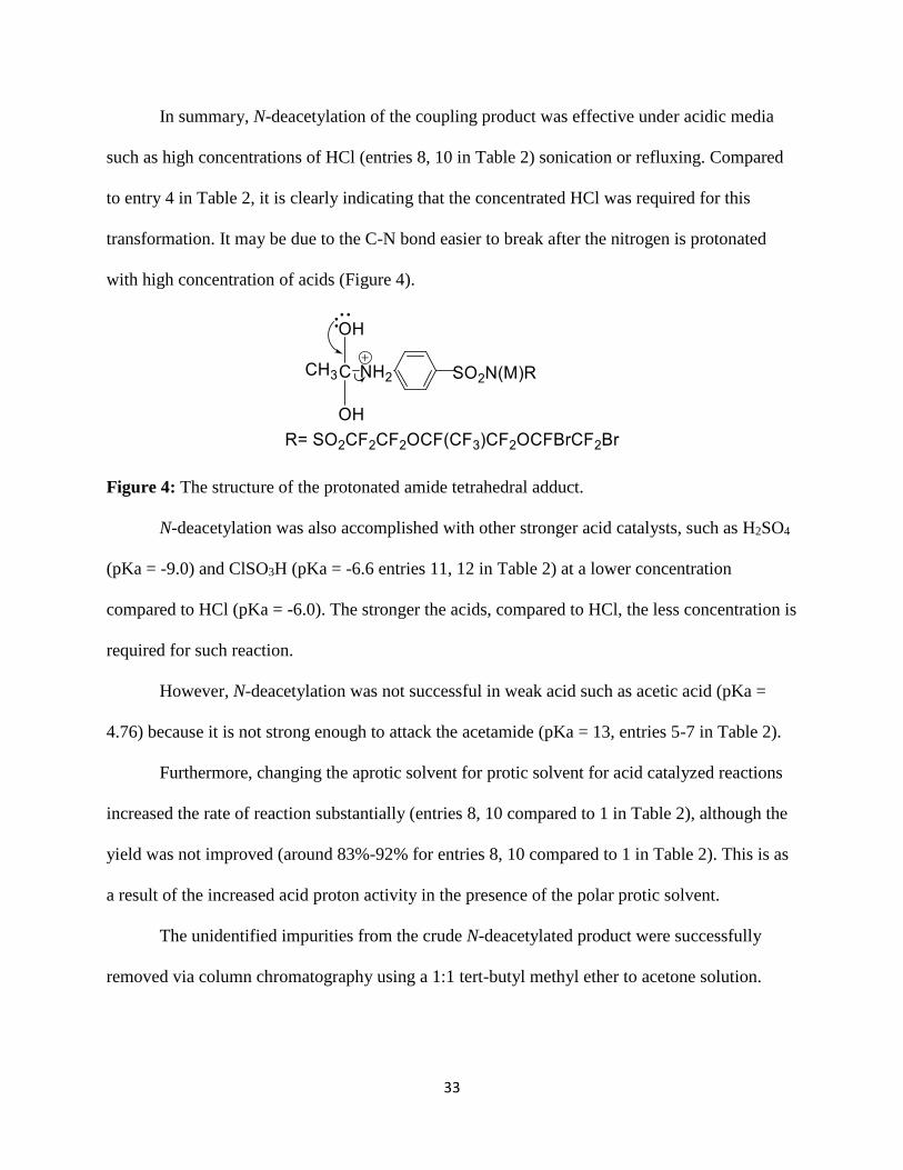
In summary, N-deacetylation of the coupling product was effective under acidic media
such as high concentrations of HCl (entries 8, 10 in Table 2) sonication or refluxing. Compared
to entry 4 in Table 2, it is clearly indicating that the concentrated HCl was required for this
transformation. It may be due to the C-N bond easier to break after the nitrogen is protonated
with high concentration of acids (Figure 4).
Figure 4: The structure of the protonated amide tetrahedral adduct.
N-deacetylation was also accomplished with other stronger acid catalysts, such as H2SO4
(pKa = -9.0) and ClSO3H (pKa = -6.6 entries 11, 12 in Table 2) at a lower concentration
compared to HCl (pKa = -6.0). The stronger the acids, compared to HCl, the less concentration is
required for such reaction.
However, N-deacetylation was not successful in weak acid such as acetic acid (pKa =
4.76) because it is not strong enough to attack the acetamide (pKa = 13, entries 5-7 in Table 2).
Furthermore, changing the aprotic solvent for protic solvent for acid catalyzed reactions
increased the rate of reaction substantially (entries 8, 10 compared to 1 in Table 2), although the
yield was not improved (around 83%-92% for entries 8, 10 compared to 1 in Table 2). This is as
a result of the increased acid proton activity in the presence of the polar protic solvent.
The unidentified impurities from the crude N-deacetylated product were successfully
removed via column chromatography using a 1:1 tert-butyl methyl ether to acetone solution.
Page 35
34
N-deacetylation was also successful in the presence of high concentrations of base under
sonication for 30 mins (entries 22 and 23 in Table 2) although side reaction of the perfluorovinyl
ether occurred.
The reaction, however, did not occur in the presence of low concentrations of base under
sonication for six hours. The complete debromination (100% for entries 13-19 in Table 2) did
happen. Therefore, neutralization of the N-deacetylated product from the acid catalyzed
hydrolysis (entries 1-4, 8-12 in Table 2) led to complete debromination of the coupling product
which shortened the overall synthesis scheme.
Figure 5: The structure of the debrominated product.
Page 36
35
CHAPTER 3
EXPERIMENTAL
General Considerations
NMR Spectroscopy
The 1H and 19F NMR spectroscopic studies were carried on a Joel JNM-ECP 400 MHz
FT-IR spectrometer. The chemical shifts are quoted in parts per million (ppm) using the high-
frequency position conversion, and the coupling constants are reported as a ‘J’ value in Hz. 1H
NMR spectra were referenced to trimethyl silane (TMS) while 19F chemical shifts were
referenced to a CFCl3 external standard. The chemical shift of residual H in CD3CN is 1.97 ppm
relative to TMS. Negative and positive chemical shifts represent upfield and downfield
respectively.
The splitting patterns of resonance were described as follows: singlet (s), doublet (d),
triplet (t), quartet (q), and multiplet (m). The NMR spectra were measured with 1-2 mmol/L
concentrations of the solutions (unless indicated otherwise) and small amounts of CFCl3 external
reference in an appropriate deuterated solvent for 19F NMR only.
Gas Chromatography-Mass Spectrometer
GC-MS were recorded on a Shimadzu GCMS-QP2010 Plus GC system spectrometer.
The samples were prepared by dissolving 10 mg of the solid samples in 1 mL of acetone.
Infra-Red Spectroscopy
The infrared spectra were recorded on the Shimadzu IR Prestige-21 FT-IR spectrometer.
The samples were prepared by putting 1 mg of the solid sample on the lens of the spectrometer.
The IR spectra were scanned from 4000 cm-1 to 450 cm-1 and reported in wavenumbers (cm-1)
with intensity abbreviations of: vs (very strong), S (strong), m (medium), w (weak), and vw
(very weak).
Page 37
36
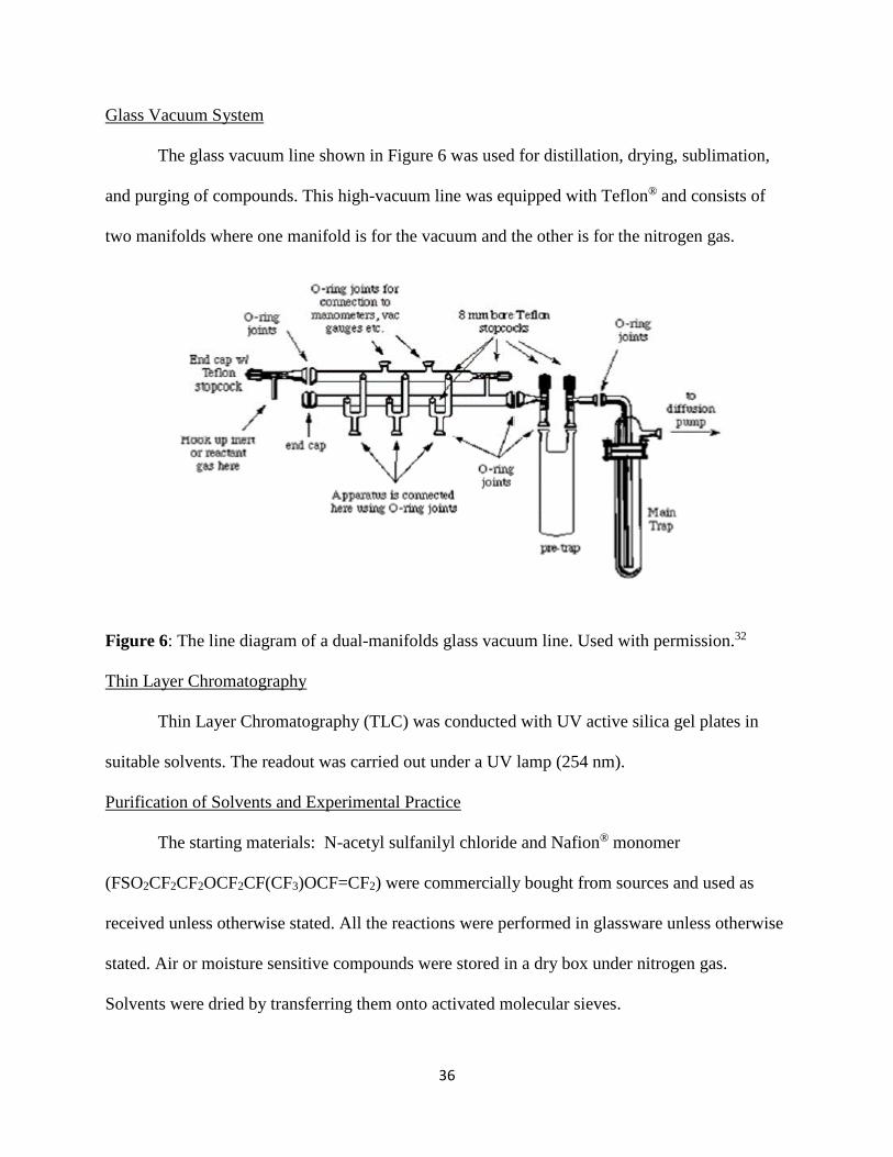
Glass Vacuum System
The glass vacuum line shown in Figure 6 was used for distillation, drying, sublimation,
and purging of compounds. This high-vacuum line was equipped with Teflon® and consists of
two manifolds where one manifold is for the vacuum and the other is for the nitrogen gas.
Figure 6: The line diagram of a dual-manifolds glass vacuum line. Used with permission.32
Thin Layer Chromatography
Thin Layer Chromatography (TLC) was conducted with UV active silica gel plates in
suitable solvents. The readout was carried out under a UV lamp (254 nm).
Purification of Solvents and Experimental Practice
The starting materials: N-acetyl sulfanilyl chloride and Nafion® monomer
(FSO2CF2CF2OCF2CF(CF3)OCF=CF2) were commercially bought from sources and used as
received unless otherwise stated. All the reactions were performed in glassware unless otherwise
stated. Air or moisture sensitive compounds were stored in a dry box under nitrogen gas.
Solvents were dried by transferring them onto activated molecular sieves.
Page 38
37
Synthesis of 4-sulfamonylacetanilide
In a typical procedure, N-acetyl sulfanilyl chloride (5.01g, 0.0225 mol) was dissolved in
30 mL of ammonia hydroxide (28-30%) and 20 mL of acetonitrile in a 100 mL round bottomed
flask. The solution was refluxed for 24 hrs at 90 oC and the volatile material was removed using
a rotary evaporator. The solid crude product was recrystallized from a water-methanol solution
and then vacuum filtered. The pure product (3.39 g) of 2 was obtained with a yield of 74.1%
after drying under high vacuum for 2 hours.
1H NMR (400 MHz; CD3CN; ppm): δa 2.12 (3H, s), δb 8.67 (1H, s), δc 7.81 (2H, d),
δd 7.74 (2H, d), JCD = 4 Hz, and δe 5.62 (2H, s).
IR (νmax/cm-1): 3250 m (NH), 1670 m (C=O), 1550 m (NH) and 1300 s (S=O).
m/z: 43 (M+, 100%), 214, 172, 156, 108, 92 and 65.
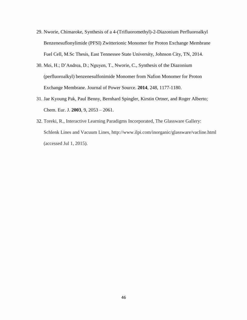
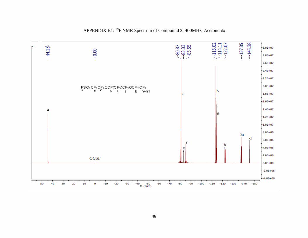
Synthesis of FSO2CF2CF2OCF(CF3)CF2OCFBrCF2Br
In a typical procedure, Nafion® monomer FSO2CF2CF2OCF2CF(CF3)OCF=CF2 (10.0 g,
22.4 mmol) was added into a 25 mL round bottom flask containing a stir bar. The flask was put
in an ice bath at 0 oC. Bromine (2 mL, 39.0 mmol) was added slowly using a pressure equalizing
funnel for about 2 hours. Persistence of a reddish color for 30 mins indicated that there was
excess bromine. The excess bromine remained in the funnel and as the reaction was allowed to
continue overnight in the presence of light, some bromine dissociated and was made available as
Br2(g) encouraging the free radical reaction.
Page 39
38
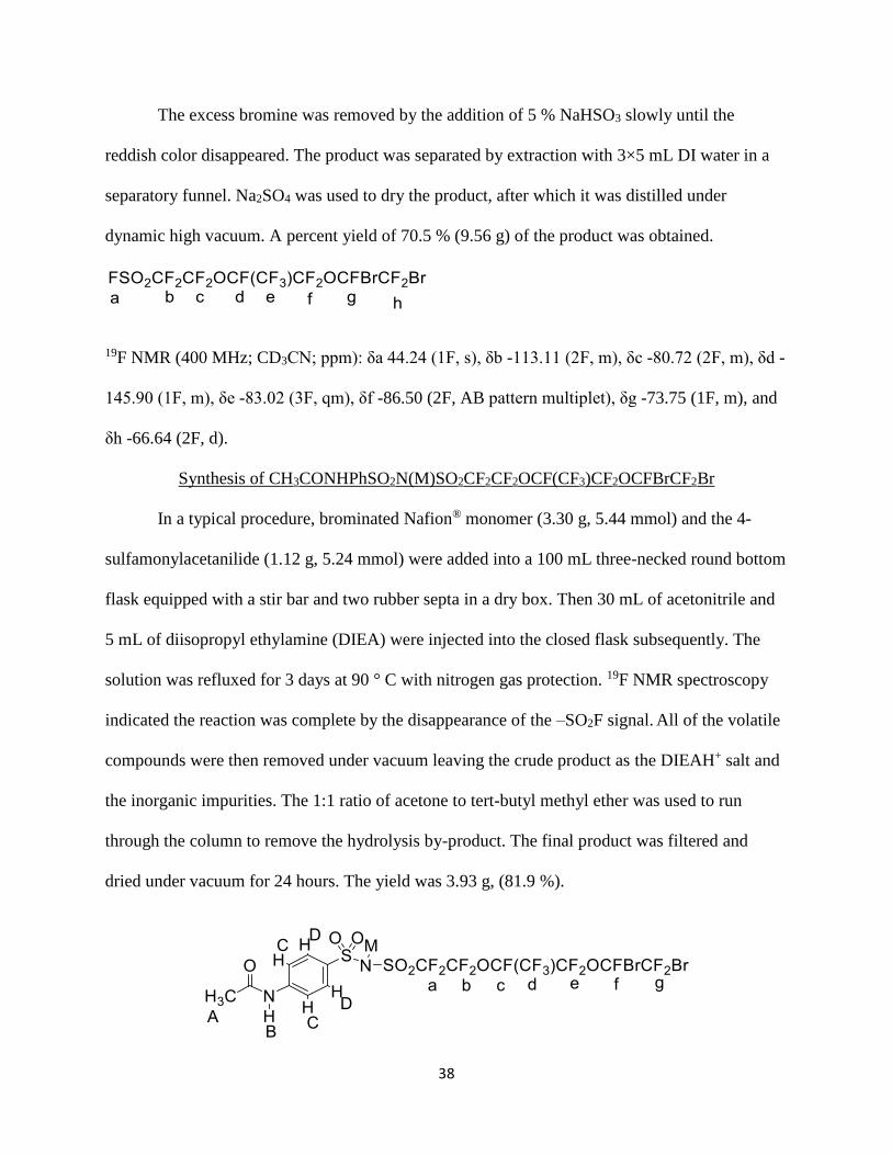
The excess bromine was removed by the addition of 5 % NaHSO3 slowly until the
reddish color disappeared. The product was separated by extraction with 3×5 mL DI water in a
separatory funnel. Na2SO4 was used to dry the product, after which it was distilled under
dynamic high vacuum. A percent yield of 70.5 % (9.56 g) of the product was obtained.
19F NMR (400 MHz; CD3CN; ppm): δa 44.24 (1F, s), δb -113.11 (2F, m), δc -80.72 (2F, m), δd -
145.90 (1F, m), δe -83.02 (3F, qm), δf -86.50 (2F, AB pattern multiplet), δg -73.75 (1F, m), and
δh -66.64 (2F, d).
Synthesis of CH3CONHPhSO2N(M)SO2CF2CF2OCF(CF3)CF2OCFBrCF2Br
In a typical procedure, brominated Nafion® monomer (3.30 g, 5.44 mmol) and the 4-
sulfamonylacetanilide (1.12 g, 5.24 mmol) were added into a 100 mL three-necked round bottom
flask equipped with a stir bar and two rubber septa in a dry box. Then 30 mL of acetonitrile and
5 mL of diisopropyl ethylamine (DIEA) were injected into the closed flask subsequently. The
solution was refluxed for 3 days at 90 ° C with nitrogen gas protection. 19F NMR spectroscopy
indicated the reaction was complete by the disappearance of the –SO2F signal. All of the volatile
compounds were then removed under vacuum leaving the crude product as the DIEAH+ salt and
the inorganic impurities. The 1:1 ratio of acetone to tert-butyl methyl ether was used to run
through the column to remove the hydrolysis by-product. The final product was filtered and
dried under vacuum for 24 hours. The yield was 3.93 g, (81.9 %).
Page 40
39
19F NMR (400 MHz; CD3CN; ppm): δa -115.41 (2F, m), δb -80.72 (2F, m), δc -144.77 (1F, m),
δd -78.63 (3F, qm), δe -85.10 (2F, AB pattern multiplet), δf -71.83 (1F, m), and δg -63.65 (2F,
d).
1H NMR (400 MHz; CD3CN; ppm): δA 2.16 (3H, s), δB 9.53 (1H, s), δC 7.85 (2H, d), δD 7.78
(2H, d) and JCD = 4 Hz.
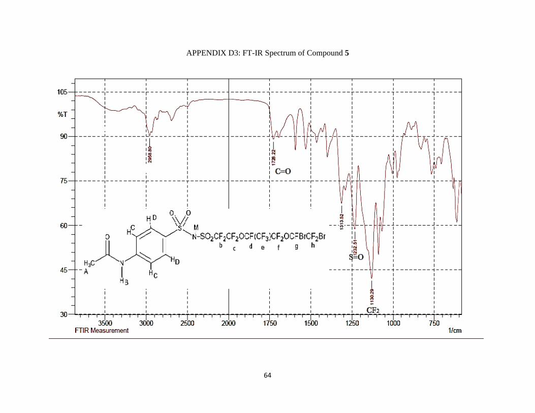
IR (νmax/cm-1): 3400 (NH), 1728.22 m (C=O), 1313.52 m and 1232.51 s (S=O), 1130.29 vs
(CF2).
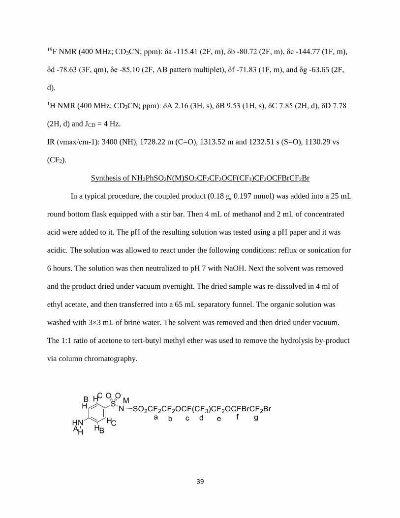
Synthesis of NH2PhSO2N(M)SO2CF2CF2OCF(CF3)CF2OCFBrCF2Br
In a typical procedure, the coupled product (0.18 g, 0.197 mmol) was added into a 25 mL
round bottom flask equipped with a stir bar. Then 4 mL of methanol and 2 mL of concentrated
acid were added to it. The pH of the resulting solution was tested using a pH paper and it was
acidic. The solution was allowed to react under the following conditions: reflux or sonication for
6 hours. The solution was then neutralized to pH 7 with NaOH. Next the solvent was removed
and the product dried under vacuum overnight. The dried sample was re-dissolved in 4 ml of
ethyl acetate, and then transferred into a 65 mL separatory funnel. The organic solution was
washed with 3×3 mL of brine water. The solvent was removed and then dried under vacuum.
The 1:1 ratio of acetone to tert-butyl methyl ether was used to remove the hydrolysis by-product
via column chromatography.
Page 41
40
19F NMR (400 MHz; CD3CN; ppm): δa -115.41 (2F, m), δb -80.72 (2F, m), δc -144.77 (1F, m),
δd -78.63 (3F, qm), δe -85.10 (2F, AB pattern multiplet), δf -71.83 (1F, m), and δg -63.65 (2F,
d).
1H NMR (400 MHz; CD3CN; ppm): δA 4.78 (2H, s), δB 7.55 (2H, d), δC 6.61 (2H, d) and JBC =
4 Hz.
IR (νmax/cm-1): 3064.89 (NH), 1300 m and 1232.51 s (S=O), 1115 vs (CF2).
Synthesis of NH2PhSO2N(M)SO2CF2CF2OCF(CF3)CF2OCF=CF2
In a typical procedure, the coupled product (0.18 g, 0.197 mmol) was added into a 25 mL
round bottom flask equipped with a stir bar. Then 5 mL of methanol and 6 ml of base were added
to it. The pH of the resulting solution was tested using a pH paper and it was basic. The solution
was allowed to react under sonication for 6 hours. Next the solvent was removed and dried under
vacuum overnight. The dried sample was re-dissolved in 4 mL of ethyl acetate, and then
transferred into a 65 mL separatory funnel. The organic solution was washed with 3×3 mL of
brine water. The solvent was then removed and dried under vacuum.
19F NMR (400 MHz; CD3CN; ppm): δa -115.41 (2F, m), δb -80.72 (2F, m), δc -144.77 (1F, m),
δd -78.63 (3F, qm), δe -85.10 (2F, AB pattern multiplet), δf -112.31 (1F, m), δg1 -135.58 (2F, m)
and δg -121.31 (2F, m).
1H NMR (400 MHz; CD3CN; ppm): δA 4.78 (2H, s), δB 7.55 (2H, d), δC 6.61 (2H, d) and JBC =
4 Hz.
IR (νmax/cm-1): 3064.89 (NH), 1300 m and 1232.51 s (S=O), 1115 vs (CF2).
Page 42
41
CHAPTER 4
CONCLUSION
An alternative synthetic path has successfully been developed for the synthesis of PFSI
diazonium zwitterionic monomers. In this method development, four different compounds were
successfully synthesized and characterized. The synthesized compounds obtained are 4-
sulfamonylacetanilide, FSO2CF2CF2OCF(CF3)CF2OCFBrCF2Br,
CH3CONHPhSO2N(M)SO2CF2CF2OCF(CF3)CF2OCFBrCF2Br and
NH2PhSO2N(M)SO2CF2CF2OCF(CF3)CF2OCF=CF2 from the ammonolysis, bromination,
coupling and N-deacetylation reactions respectively.
Ammonolysis of 4-sulfamonylacetanilide was achieved by reacting N-acetyl sulfanilyl
chloride and ammonium hydroxide in a ratio of 1:2 under reflux overnight. Similarly protection
of the sensitive double bonds of the Nafion® monomer was accomplished in a free radical
reaction where the monomer was reacted with bromine liquid at 0 oC overnight. Coupling of 4-
sulfamonylacetanilide and the brominated Nafion® monomer occurred in the presence of
diisopropyl ethyl amine and acetonitrile under reflux for three days. The ratio of 1:1.04 of amide
to Nafion® monomer was used in order to have enough of the monomer to react with the amide
after part of it had hydrolyzed.
The N-deacetylation of 4-acetamido-perfluoroalkylbenzenesulfonimide occurred in the
presence of strong acid catalysts under reflux and sonication for six hours in methanol. The
reaction time was short compared to regular acetamides due to the electron withdrawing
perfluoroalkyl group which destabilizes the carbon-nitrogen bond. This optimized condition will
help in the study of the scope of structurally different aromatic acetamides for the synthesis of
PFSI diazonium zwitterionic monomers due to ease in purification, short reaction time and
Page 43
42
relatively high yields. The debromination of the protected perfluoro vinyl ether was perceived to
have occurred via neutralization of the N-deacetylated product. It will shorten the overall
synthesis scheme for PFSI monomers. Furthermore, changing the solvent from an aprotic one to
a protic solvent increased the rate of the reaction significantly.
N-deacetylation in the presence of base at high concentrations was successful although
side reactions of the perfluorovinyl ether group occurred. Meanwhile, at low concentrations of
base the N-deacetylation was not successful but debromination happened instead.
Page 44
43
REFERENCES
1. Dewick P.M; Medicinal Natural Products: A Biosynthetic Approach, 3rd ed., Wiley,
West Sussex, 2009, 311 – 484.
2. Gutekunst W. R, Baran P. S, The Royal Society of Chemistry, Chem. Soc. Rev. 2011,
40(4), 1976-1991.
3. Wuts P. G. M., Greene T. W., Protective Groups in Organic Synthesis, 4th ed., Wiley-
Interscience, Hoboken, 2006, 773-789.
4. Karty J.; Organic Chemistry, Principles and Mechanism, 1st ed., W. W. Norton and
Company, New York –London, 2014, pp 1011-1027.
5. Shimizu, Y.; Morimoto, H.; Zhang, M.; Ohshima, T., Microwave-Assisted Deacylation
of Unactivated Amides Using Ammonium-Salt-Accelerated Transamidation.
Angewandte Chemie International Edition. 2012, 51(34), 8564-8567.
6. Coetzee, J.; Dodds, D.; Klankermayer, J., Homogeneous Catalytic Hydrogenation of
Amides to Amines. Chemistry - A European Journal. 2013, 19(33), 11039-11050.
7. Sultane, P.; Mete, T.; Bhat, R., Chemoselective N-deacetylation under mild conditions.
Organic and Bimolecular Journal, 2014, 12, 261-264.
8. Cao, Y.; Du, D.; Yang, X.; Xu, X., Deprotection of acetyl group on amino group with
thionyl chloride and pyridine. Journal of Agricultural Science and Technology, 2012, 13,
1-3.
9. Wang, G.; Wang, L.; Li, C.; Sun, J., A facile and efficient method for the selective
deacylation of N-arylacetamides and 2-chloro-N-arylacetamides catalyzed by SOCl2.
Research on Chemical Intermediates, 2012, 38, 77-89.
Page 45
44
10. Medina-Ramos, W.; Mojica, M.; Cope, E.; Hart, R., Water at elevated temperatures
(WET): reactant, catalyst, and solvent in the selective hydrolysis of protecting groups.
Green Chemistry, 2014, 16, 2147-2155.
11. Easwaramurthy, M.; Ravikumar, R.; Lakshmanan, A.; Raju, G., Ecofriendly solvent-free
microwave-enhanced thermal Fries rearrangement of anilides and phenyl ureas. Indian
Journal of Chemistry, 2005, 44B (3), 635-637.
12. Xiuli, Z.; Kai, L.; Wei, C.; Lei, W., Amide hydrolysis reaction catalyzed by KFAl2O3
under microwave irradiation and solvent-free conditions. Chinese Journal of Chemistry,
2011, 29(10), 2209-2212.
13. White, E. Journal of American Chemical Society, 1955, 77, 6011.
14. Badwal, S.P.S.; Giddey, S.; Kulkarni, A.; Goel, J.; Basu, S. (May 2015). "Direct ethanol
fuel cells for transport and stationary applications, a comprehensive review". Applied
Energy 145: 80–103.
15. Barbir, F.; Braun, J.; Neutzler, J. Properties of Molded Graphite Bi-Polar Plates for PEM
Fuel Cells. Int. J. on New Materials for Electrochemical System. 1999, 2,197-200.
16. Hickner, M.; Ghassemi, H.; Kim, Y.S.; Einsla, B.; McGrath, J.E. Alternative Polymer
Systems for Proton Exchange Membranes (PEMs). Chem. Rev. 2004, 104, 4587-4612.
17. National Energy Technology Laboratory, Science Applications International Coporation
US Department of Energy, Parson, Fuel cells hand book, EG&G Services, Office of
Fossil Energy, 5th ed,; 2000.
18. Acres, G. J. K.; Frost, J. C.; Hards, G. A.; Potter, R. J.; Ralph, T. R.; Thompsett, D.;
Burstein, G. T.; Hutchings, G. J. Electrocatalysts for Fuel Cells. Catal. Today, 1997, 38.
Page 46
45
19. Ralph, T. R.; Hards, G. A. Fuel cells: Clean Energy Production for the New Millennium.
Chem Ind, Lond, 1998, 8, 334.
20. Kim, J.; Kim, B.; Jung, B. Proton Conductivities and Methanol Permeabilities of
Membranes Made from Partially Sulfonated Polystyrene-block-Poly (ethylene
ranbutylene)-block-Polystyrene Copolymers. J. Membr. Sci. 2002, 207, 129-137.
21. Gibson, M.S., ‘The Chemistry of the Amino Group’, Patai Second Edition; Interscience:
New York, 1989, 37.
22. Karady, S.; Amato, J. S.; Weinstock, L. M.; Sletzinger, M., Tetrahedron Letters. 1978,
19, 407
23. Thampan, T.; Malhotra, S.; Zhang, J.; Datta R. PEM Fuel Cell as a Membrane Reactor.
Catal. Today, 2001, 67[1-3], 15-32.
24. Moilanen, D. E., Spry, D. B., Fayer, M. D.Water Dyanmics and Proton Transfer in
Nafion Fuel Cell Membranes. Langmuir 2008, 24 [8], 3690-3698.
25. Wilson, M. S.; Gottesfeld, S. Thin-Film Catalyst Layers for Polymer Electrolyte Fuel
Cell Electrodes. J. Appl. Electrochem.1992, 22, 1.
26. Ryan Baker and Jiujun Zhang Institute for fuel cell innovation. National Research of
Canada, 4250 Wesbrook Mall, Vancouver, British Columbia V6T 1W5, Canada, 2011.
27. Laughin R. G. HLB from a Thermodynamic Perspective J. Soc. Cosmet. Chem.
1981, 32, 371.
28. Creager, S.E., B. Liu, H. Mei, and D. DesMarteau, Electrochemical grafting of an aryl
fluorosulfonimide electrolyte onto glassy carbon. Langmuir, 2006, 22(25), 10747-10753.
Page 47
46
29. Nworie, Chimaroke, Synthesis of a 4-(Trifluoromethyl)-2-Diazonium Perfluoroalkyl
Benzenesuflonylimide (PFSI) Zwitterionic Monomer for Proton Exchange Membrane
Fuel Cell, M.Sc Thesis, East Tennessee State University, Johnson City, TN, 2014.
30. Mei, H.; D’Andrea, D.; Nguyen, T., Nworie, C., Synthesis of the Diazonium
(perfluoroalkyl) benzenesulfonimide Monomer from Nafion Monomer for Proton
Exchange Membrane. Journal of Power Source. 2014, 248, 1177-1180.
31. Jae Kyoung Pak, Paul Benny, Bernhard Spingler, Kirstin Ortner, and Roger Alberto;
Chem. Eur. J. 2003, 9, 2053 – 2061.
32. Toreki, R., Interactive Learning Paradigms Incorporated, The Glassware Gallery:
Schlenk Lines and Vacuum Lines, http://www.ilpi.com/inorganic/glassware/vacline.html
(accessed Jul 1, 2015).
Page 48
47
APPENDICES
APPENDIX A: GC-MS Chromatogram of Compound 2
Page 49
48
APPENDIX B1: 19F NMR Spectrum of Compound 3, 400MHz, Acetone-d6
Page 50
49
APPENDIX B2: 19F NMR Spectrum of Compound 4, 400MHz, CD3CN
Page 51
50
APPENDIX B3: Expanded 19F NMR Spectrum of Compound 4, 400MHz, CD3CN
Page 52
51
APPENDIX B4: 19F NMR Spectrum of Compound 5, 400MHz, CD3CN
Page 53
52
APPENDIX B5: 19F NMR Spectrum of Compound 6, 400MHz, CD3CN
Page 54
53
APPENDIX B6: 19F NMR Spectrum of Compound 6’, 400MHz, CD3CN
Page 55
54
APPENDIX B7: 19F NMR Spectrum of Basic Hydrolysis Byproduct, 400MHz, CD3CN
Page 56
55
APPENDIX C1: 1H NMR Spectrum of Compound 1, 400MHz, Acetone-d6
Page 57
56
APPENDIX C2: 1H NMR Spectrum of Compound 2, 400MHz, CD3CN
Page 58
57
APPENDIX C3: Expanded 1H NMR Spectrum of Compound 2, 400MHz, CD3CN
Page 59
58
APPENDIX C4: 1H NMR Spectrum of Compound 5, 400MHz, CD3CN
Page 60
59
APPENDIX C5: Expanded 1H NMR Spectrum of Compound 5, 400MHz, CD3CN
Page 61
60
APPENDIX C6: 1H NMR Spectrum of Compound 6, 400MHz, CD3CN
Page 62
61
APPENDIX C7: Expanded 1H NMR Spectrum of Compound 6, 400MHz, CD3CN
Page 63
62
APPENDIX D1: FT-IR Spectrum of Compound 1
Page 64
63
APPENDIX D2: FT-IR Spectrum of Compound 2
Page 65
64
APPENDIX D3: FT-IR Spectrum of Compound 5
Page 66
65
APPENDIX D4: FT-IR Spectrum of Compound 6
Page 67
66
VITA
GRACE ABBAN
Education: M.S. Chemistry, East Tennessee State University, Johnson City,
Tennessee, 2015
B.S. Chemistry, University of Cape Coast, Cape Coast, Ghana,
2012
Professional Experience: Graduate Teaching Assistant, East Tennessee State University,
College of Arts and Sciences, 2013-2015
Teaching Assistant, University of Cape Coast, Department of
Chemistry, 2012-2013
Chemistry Teacher, Klutse Amuzu Senior High School, Tarkwa,
Ghana, 2012
Laboratory Analyst, Goldfields Ghana Ltd., Tarkwa, 2011
Publications: Barku, Y. A. V.; Ahiadu, B. K.; Abban, G. Phytochemical Studies
and Antioxidant Properties of Methanolic and Aqueous Extracts of
the Leaves of Mallotus Oppositifolius. Journal of Basic & Applied
Sciences. 2013, 1(1), 20-31
Barku, Y. A. V.; Abban, G. Phytochemical Studies, In-vitro
Antibacterial Activities and Antioxidant Properties of the
Methanolic and Ethyl Acetate Extracts of the Leaves of
Anogeissus leiocarpus. International Journal of Biochemistry
Research & Review. 2013, 3(2), 137-145


![2013 Discovery of N-(benzo[1,2,3]triazol-1-yl)-N-(benzyl)acetamido)phenyl) carboxamides as severe acute respiratory synd](https://static.documents.pub/doc/80x56/613ca6919cc893456e1e8458/2013-discovery-of-n-benzo123triazol-1-yl-n-benzylacetamidophenyl-carboxamides.jpg)


