This paper describes some methods for producing developable surfaces withpractical applications for creating useful lightweight, rigid, jig-less and elegant structuralforms from sheet materials. Multiple related techniques based on the same fundamentalprinciple can be used to generate a variety of interesting singly curved and doubly curvedshapes. The system requires a minimum of specialist software, and is described in simplesteps that can be followed by the reader with access to basic 3D CAD tools.
Buildings 2012, 2, 424-455; doi:10.3390/buildings2040424 OPEN ACCESS buildings ISSN 2075-5309 www.mdpi.com/journal/buildings Article Methods for Creating Curved Shell Structures From Sheet Materials Bruno Postle Capita Symonds Structures, Sheffield, S1 2DU, UK; E-Mail: [email protected]Received: 12 July 2012; in revised form: 5 September 2012 / Accepted: 11 October 2012 / Published: 19 October 2012 Abstract: This paper describes some methods for producing developable surfaces with practical applications for creating useful lightweight, rigid, jig-less and elegant structural forms from sheet materials. Multiple related techniques based on the same fundamental principle can be used to generate a variety of interesting singly curved and doubly curved shapes. The system requires a minimum of specialist software, and is described in simple steps that can be followed by the reader with access to basic 3D CAD tools. Keywords: architectural geometry; developable surface; panelisation 1. Introduction Curved surface shell structures can be used to create very useful, lightweight, rigid structural forms. This paper looks at just one technique of producing shell structures, utilising bent strips of sheet material such as steel plate or plywood, joined together into rigid tubes or shells. Sheet materials can only be bent/curved in particular ways, essentially limited to the surfaces of cylinders and cones, or combinations of various sized cylinders and cones (i.e., surfaces with zero Gaussian curvature). What is not generally practical is deforming sheet materials into doubly-curved spherical (synclastic) or saddle-shaped/twisted (anticlastic) shapes, as these require plastic deformation possible only by applying large forces and/or heat. So what we need is what are called developable surfaces, or rather, shapes that can be assembled from more than one developable surface. A developable surface is a shape that can be formed by simple bending of a sheet material without any twisting or other plastic deformation of the material.
Received: 12 July 2012; in revised form: 5 September 2012 / Accepted: 11 October 2012 /Published: 19 October 2012
Abstract: This paper describes some methods for producing developable surfaces withpractical applications for creating useful lightweight, rigid, jig-less and elegant structuralforms from sheet materials. Multiple related techniques based on the same fundamentalprinciple can be used to generate a variety of interesting singly curved and doubly curvedshapes. The system requires a minimum of specialist software, and is described in simplesteps that can be followed by the reader with access to basic 3D CAD tools.
Curved surface shell structures can be used to create very useful, lightweight, rigid structural forms.This paper looks at just one technique of producing shell structures, utilising bent strips of sheet materialsuch as steel plate or plywood, joined together into rigid tubes or shells.
Sheet materials can only be bent/curved in particular ways, essentially limited to the surfaces ofcylinders and cones, or combinations of various sized cylinders and cones (i.e., surfaces with zeroGaussian curvature).
What is not generally practical is deforming sheet materials into doubly-curved spherical (synclastic)or saddle-shaped/twisted (anticlastic) shapes, as these require plastic deformation possible only byapplying large forces and/or heat.
So what we need is what are called developable surfaces, or rather, shapes that can be assembledfrom more than one developable surface. A developable surface is a shape that can be formed by simplebending of a sheet material without any twisting or other plastic deformation of the material.
Buildings 2012, 2 425
At first glance it is not entirely obvious how complex shapes can be created that consist of more thanone developable surface. This paper introduces five related techniques for generating such surfaces thatallow a vast variety of previously impractical shapes to be produced.
Most approaches to this problem to date have been to generate doubly-curved shapes with tools suchas NURBS patches and then attempt to find developable surfaces that approximate these shapes. Thispaper introduces a productive technique that works by limiting the range of doubly-curved shapes to asubset that can be simply broken down into developable surfaces. This limitation is that the surfaces arerulings between pairs of carefully constructed splines rather than free-form NURBS patches.
2. Previous Work
Developable surfaces are a powerful geometrical technique for assembling curved structures fromsheet materials, perhaps best known through the practice of the architect Frank Gehry [1] and the curvedcladding systems used in their buildings.
The computer scientist Dr. David Huffman was a pioneer of techniques for curved folding of sheetmaterials to result in developable curved surfaces. Note that although fascinating mathematically, therequirement for both sides of the fold to belong to the same planar sheet is not that interesting forlarge scale structural design. There have been developments of these techniques [2] using computersimulations to devise quite intricate and beautiful three dimensional shapes.
Other useful techniques are a subdivision approach to devise curved developable surfaces from coarseplanar quadrilateral meshes [3], a technique for fitting developable singly curved strips to arbitrary free-form surfaces [4], and fitting small single and double curved panels to arbitrary free-form surfaces [5].The textbook Architectural Geometry [6] contains a general summary of many of these techniques.
A technique with many similarities to those described in this paper is the process of Schlaich,Bergermann and Partners for the creation of scale-trans-surfaces, described by Shelden [1]. Here adirectrix line is used to loft a generatrix line, with a scaling law applied to modify the curve along theloft. This produces surfaces equivalent to method four below, somewhat complicated by the need for thescaling law abstraction.
The method for creating developable surfaces explored here is to rule a surface between two splines;however, not all pairs of splines have a practical developable solution. One method of forcing adevelopable solution is to construct splines using the edges of a series of linked planar quadrilaterals.So long as each quadrilateral is planar, the established theory, as described by Shelden, is that adevelopable surface can be generated between them. However, even with these constraints, a simple threequadrilateral geometry can be constructed that can only be developed by introducing ugly singularities(Figure 2).
A more general form of this theory is that many, but not all, pairs of splines can be ruled if the endquadrilaterals are planar. The subset of these splines that are also convex ‘C’ shaped rather than ‘S’shaped can always be developed, as can all ‘O’ shaped closed splines that are continuously convex, seeFigures 3 and 4.
Buildings 2012, 2 426
Figure 1. Two ‘S’ shaped splines constructed using edges of three connected planarquadrilaterals. Note that the two splines are not in the same plane and indeed that theyneed not even be planar.
Figure 2. Attempting to create a developable surface from two ‘S’ shaped splines above,this surface can only be made developable by introducing the radial singularity shown at thetop-middle.
Buildings 2012, 2 427
Figure 3. ‘C’ and ‘O’ shaped simple developable surfaces and their construction. The redand green quadrilaterals are each planar, however none of the blue quadrilaterals need to beplanar in order to generate developable surfaces.
Figure 4. ‘C’ and ‘O’ shaped simple developable surfaces unrolled. Note that the rulinglines are irregular. They are neither radial nor parallel, but change direction constantly alongthe length.
Buildings 2012, 2 428
3. Triangles and Quadrilaterals
Typically, a developable surface is represented as a series of very slender triangles or planarquadrilaterals. The process of developing the surface is simply to measure each triangle/quadrilateralin turn and to redraw them on a two dimensional surface. This process is quite time-consuming, so it isusually performed in software.
Of course with a little bit of effort it is possible to demonstrate that any surface can be triviallydeconstructed to triangles, but not all triangular surfaces are usefully developable. A series of alternatingleft-right triangles may only be developable by introducing creases. An example would be a simplecorkscrew shape—this is of no use if we want a smooth surface. A series of left-left triangles producesa cone shape. This is nicely developable but the apex of the cone where all triangles meet is practicallyimpossible to roll from a sheet material.
In practice, the only shapes that are usefully developable are those consisting of a series of planarquadrilaterals that share one or both of the following properties.
• Consecutive creases share a common intersection—this is the basis of a ‘conical’ roll.
• Consecutive creases are parallel—this is the basis of a ‘cylindrical’ roll.
These two properties are central to the following five related methods.
4. Method One
Principle: Ruling between two edges that have a simple scale (homothetic) transformationrelationship generates conical surfaces consisting of planar quadrilaterals with both parallel edges andintersecting creases.
For example, take a single line in three dimensional space, create a copy and scale it any amount,draw a quadrilateral between these two lines, as with Figure 5.
Note that:
• This quadrilateral is planar.
• This quadrilateral has two parallel edges.
• This quadrilateral has two edges that intersect at the origin of the scale transformation.
Buildings 2012, 2 429
Figure 5. Two parallel homothetic lines (red), scale origin, two radial edges (green) andresulting planar quadrilateral.
Now let us take a ‘polyline’ that consists of more than one segment, copy and scale as before, anddraw quadrilaterals between each of the segments, as with Figure 6. Note that the polyline does notitself need to be planar.
• All remaining edges intersect at the origin of the scale transformation.
• This is a developable surface.
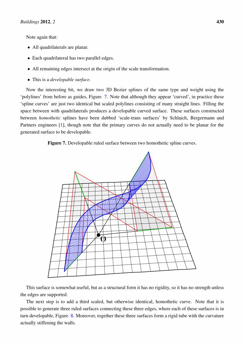
Now the interesting bit, we draw two 3D Bezier splines of the same type and weight using the‘polylines’ from before as guides, Figure 7. Note that although they appear ‘curved’, in practice these‘spline curves’ are just two identical but scaled polylines consisting of many straight lines. Filling thespace between with quadrilaterals produces a developable curved surface. These surfaces constructedbetween homothetic splines have been dubbed ‘scale-trans surfaces’ by Schlaich, Bergermann andPartners engineers [1], though note that the primary curves do not actually need to be planar for thegenerated surface to be developable.
Figure 7. Developable ruled surface between two homothetic spline curves.
This surface is somewhat useful, but as a structural form it has no rigidity, so it has no strength unlessthe edges are supported.
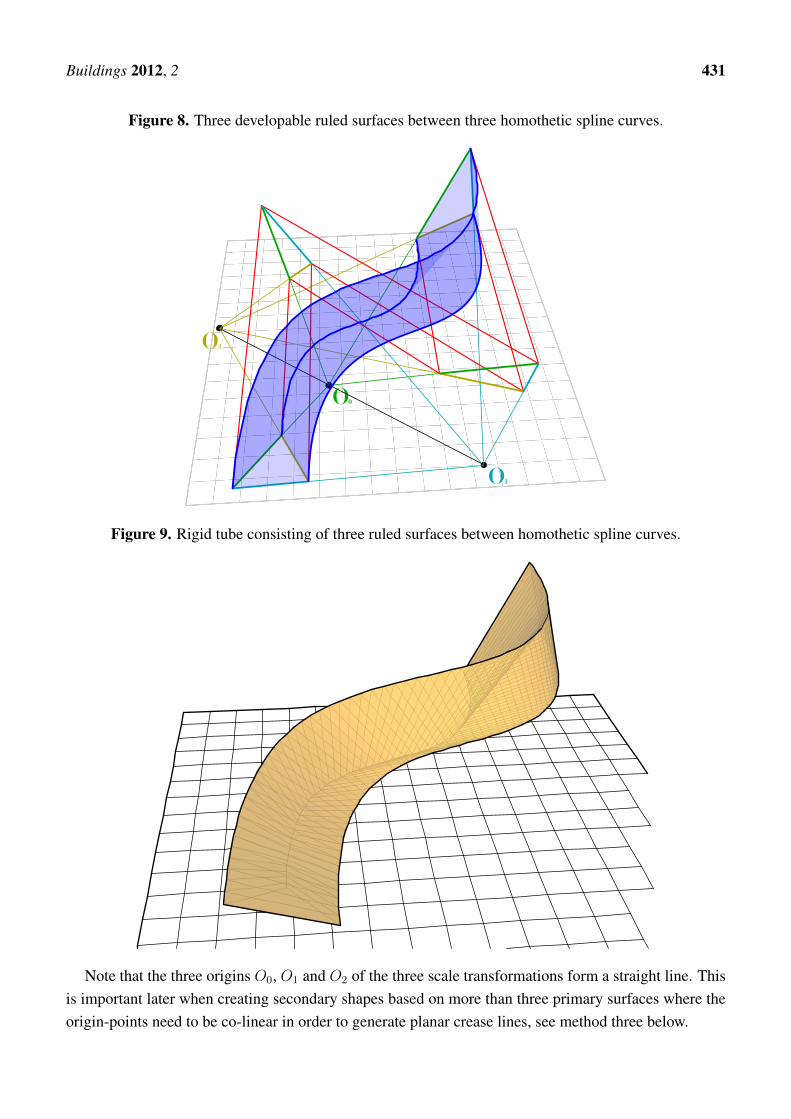
The next step is to add a third scaled, but otherwise identical, homothetic curve. Note that it ispossible to generate three ruled surfaces connecting these three edges, where each of these surfaces is inturn developable, Figure 8. Moreover, together these three surfaces form a rigid tube with the curvatureactually stiffening the walls.
Buildings 2012, 2 431
Figure 8. Three developable ruled surfaces between three homothetic spline curves.
Figure 9. Rigid tube consisting of three ruled surfaces between homothetic spline curves.
Note that the three origins O0, O1 and O2 of the three scale transformations form a straight line. Thisis important later when creating secondary shapes based on more than three primary surfaces where theorigin-points need to be co-linear in order to generate planar crease lines, see method three below.
Buildings 2012, 2 432
Note that with these ruled surfaces, the spacing of the quadrilaterals can be either equally spacedalong the length, or can be based on the spline interpolation interval—which are otherwise generally notequivalent for any pair of spline curves. For the other methods (methods two, three and four) care mustbe taken not to equally rule the quadrilaterals along the length, as this cannot be guaranteed to generatedevelopable surfaces.
Three edges can be used to generate a stiff tube (Figures 9 and 10). Tubes can also be generated withmore than three edges. See method four below for a technique to generate properly doubly-curved tubesand other shapes from more than three edges.
Figure 10. Unrolled developed cutting pattern for rigid tube shown in Figure 9.
Alternatively, corrugated shells can be generated instead of doubly curved surfaces by alternatingsmaller and larger scaled versions of the primary shape and ruling between them (Figure 11).
Figure 11. A corrugated form of method one.
Buildings 2012, 2 433
5. Method Two
Principle: Ruling between two edges where the ends form parallel lines generates cylindrical surfacesconsisting of planar quadrilaterals with both parallel creases and intersecting edges.
This is an alternative to method one for generating primary singly curved shell surfaces. The resultsare closely related to the secondary surfaces generated by method three and have similar properties.
Imagine a series of polylines with a scale relationship as with method one, but instead of using theselines to generate a surface directly, add spline curves of the same type and weight using the nodes ofthese lines perpendicular to the primary polylines, a similar technique to that used in method three.
Figure 12. Scaled homothetic polylines (red) and splines drawn between nodes (blue).
Unlike method one, none of these splines are scaled homothetic copies of each other. However theyhave a separate very useful property—any pair of these splines is coincident in two dimensions, withvariation in only the third dimension. Taking a plane perpendicular to the construction lines connectingeach pair of splines, and projecting those splines onto that plane, the splines will be coincident. This isbecause the interpolated coordinates of a spline are independent for each orthogonal direction regardlessof any rotation of the coordinate space.
This means that we can draw a ruled surface between any two secondary splines and form a cylindricaldevelopable surface, i.e., all quadrilaterals in this surface have parallel edges. Note that cylindricaldevelopable surfaces are more straightforward to shape in the workshop than conical surfaces.
Buildings 2012, 2 434
Figure 13. Ruled surfaces between splines drawn between homothetic polylines.
Figure 14. Developed surfaces created using method two, note that the ends of each panelare parallel.
Buildings 2012, 2 435
The other important consideration is that it is not possible to rule this surface by equally spacingalong the spline length, since the spline has variation in the third dimension and so does not have asimple relationship between length and the subdivision interpolation points, as would be the case withhomothetic splines. The ruling needs to be constructed using the spline subdivision interpolation points,since with these the two dimensional location in the perpendicular plane is independent of any additionalvariation outside the plane.
6. Method Three
Principle: ruling between splines constructed on primary conical surface geometry created by methodone produces secondary cylindrical geometry as described in method two.
This method utilises a multi-surface shape generated by method one and uses it to generate a seriesof secondary surfaces, each of which fully developable. The resulting compound surface is effectivelydoubly-curved and forms a rigid shell.
So take a surface generated using the first technique, either with quadrilaterals ruled by equalsubdivision or with quadrilaterals ruled by spline interpolation, though the first ruling type producesaesthetically better shapes. Use the ruled edges to draw a secondary set of splines perpendicular to thesplines created in the first instance (Figure 15).
Figure 15. Homothetic splines (magenta) and their regular division into secondary geometry(blue). These create a secondary set of splines (green).
Buildings 2012, 2 436
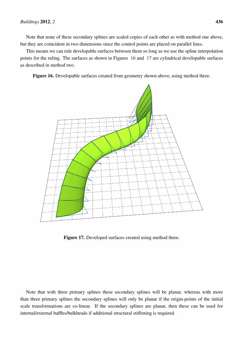
Note that none of these secondary splines are scaled copies of each other as with method one above,but they are coincident in two dimensions since the control points are placed on parallel lines.
This means we can rule developable surfaces between them so long as we use the spline interpolationpoints for the ruling. The surfaces as shown in Figures 16 and 17 are cylindrical developable surfacesas described in method two.
Figure 16. Developable surfaces created from geometry shown above, using method three.
Figure 17. Developed surfaces created using method three.
Note that with three primary splines these secondary splines will be planar, whereas with morethan three primary splines the secondary splines will only be planar if the origin-points of the initialscale transformations are co-linear. If the secondary splines are planar, then these can be used forinternal/external baffles/bulkheads if additional structural stiffening is required.
Buildings 2012, 2 437
7. Method Four
Principle: ruling between primary cylindrical surface geometry created by method two producessecondary conical surfaces as described in method one.
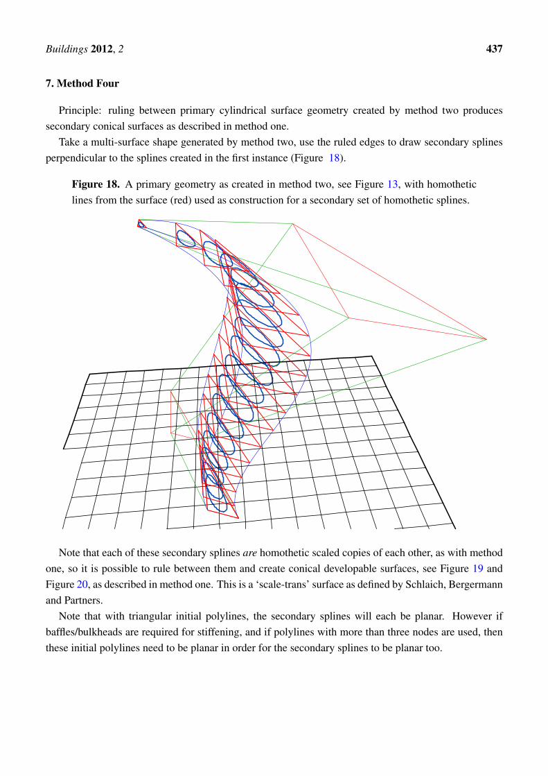
Take a multi-surface shape generated by method two, use the ruled edges to draw secondary splinesperpendicular to the splines created in the first instance (Figure 18).
Figure 18. A primary geometry as created in method two, see Figure 13, with homotheticlines from the surface (red) used as construction for a secondary set of homothetic splines.
Note that each of these secondary splines are homothetic scaled copies of each other, as with methodone, so it is possible to rule between them and create conical developable surfaces, see Figure 19 andFigure 20, as described in method one. This is a ‘scale-trans’ surface as defined by Schlaich, Bergermannand Partners.
Note that with triangular initial polylines, the secondary splines will each be planar. However ifbaffles/bulkheads are required for stiffening, and if polylines with more than three nodes are used, thenthese initial polylines need to be planar in order for the secondary splines to be planar too.
Buildings 2012, 2 438
Figure 19. Developable surfaces generated by ruling between the secondary homotheticsplines already created, see Figure 18.
Figure 20. Developed surface created with method four. This is the 3D shape shown inFigure 19.
Buildings 2012, 2 439
8. Method Five
In addition to scale and translation mapping, reflection mapping of splines can be used to createdevelopable surfaces. These produce surfaces that are similar to method two, i.e., quadrilaterals haveparallel creases (Figure 21). However it is not possible to simply generate secondary developablesurfaces from the geometry created using this method, although for many ‘C’ and ‘O’ shaped sectionsthere will be a developable solution as shown above in Figures 3 and 4.
Figure 21. Four reflection mapped splines, three mirror planes, and the generateddevelopable surfaces.
The developed surfaces created using this technique are symmetrical. Note also that the ends of each‘panel’ are parallel, see Figure 22.
Figure 22. The developed developable surfaces created using method five.
Buildings 2012, 2 440
9. Homography
Any developable surface when transformed using a plane-preserving or collineated mapping will alsobe developable. It should be self-evident that a rotation or scale transformation of a developable surfacewill also be developable. It is also true that a shear or anisotropic scale transformation of an alreadydevelopable surface will also be developable, though this is not so evident at first.
However these affine mappings are not that interesting since they can be trivially performed on thenodes of the original spline generation curves using standard CAD tools.
Of more interest is the observation that any perspective homography transformation of an existingdevelopable surface will also be developable. Most spline curves, e.g., Bezier, are invariant underperspective transformation, so it is not strictly necessary to perform the homography after the creation ofthe developable surface. However since some of the techniques above rely on the generation of equallyspaced meshes, these require that the homography step be taken after the creation of surface meshes, seeFigure 23 for an example and Figure 24 for the developed surfaces.
In detail, for the matrix of 3D coordinates in the surface model, the following homograpy needs tobe performed:
x1
y1
z1
w1
=
1 0 0 0
0 1 0 0
0 0 1 0
0 0 a 0
x0
y0
z0
1
The variable a can be any scalar value. Each x1, y1, z1 component then needs to be divided by w1:
x2
y2
z2
=
x1/w1
y1/w1
z1/w1
The resulting mesh can then be further manipulated with anisotropic scale or shear transformations.As a great number of homography transformations can be performed with wildly differing results,
parameter fitting techniques can be used to obtain an optimised shape where the requirements are notpurely artistic.
Note that planes that are parallel before transformation may not be parallel after the homography, andedges that were parallel before transformation will likely be radial after the homography.
Buildings 2012, 2 441
Figure 23. Developed surfaces before and after a perspective homography transformation.The rear shape was created using method three. The transformed developable surface at thefront is not possible to create directly through any of the five methods discussed previously.
Figure 24. Developed surfaces before and after a perspective homography transformation.The outline on the right is the untransformed shape developed, and the outline on the left isthe developed version of the transformed shape.
Buildings 2012, 2 442
10. Built Work
The Lotus sculpture for the 2012 Goodwood Festival of Speed, designed by the author in conjunctionwith the artist Gerry Judah, provides a good example of these techniques in action.
The structure has a method one geometry and the defining line is a closed spline in the form of atrefoil knot. Homothetic variants of this spline were used to generate a triangular prismatic manifoldshell. The triangular cross-section combined with the continuous curvature of the three developablesurfaces provided an extremely lightweight and rigid thin-shell structure.
The overall height is 27 metres and the total weight, not-including foundations, is 60 tonnes. Thereis no internal framework or spine. The only structural components are the three surfaces themselves.These surfaces were developed in software into 2D cutting patterns (Figure 26) and laser cut from 6 mmsteel plate. The plates were then welded together into eleven transportable sections and site-welded intothe finished piece.
Custom software was written by the author to convert the geometry into a finite element mesh thatcould be processed in the STAAD Pro structural analysis tool, where wind loading studies and structuraldynamic analysis were used to verify the structure. Observed deflections and natural frequencies in thefield under load were consistent with software predictions. A further paper will examine the design andperformance of this structure in more detail.
Figure 25. Sculpture in the form of a trefoil knot, 3D view.
Buildings 2012, 2 443
Figure 26. Sculpture in the form of a trefoil knot, unrolled panels.
Figure 27. Assembly of one segment. This is 18 m long and the full sculpture consists ofeleven different segments.
Buildings 2012, 2 444
Figure 28. Construction. The segments are installed incrementally. This photo showsthe sculpture approximately 80% complete. The props provide temporary stability duringconstruction and will be removed on completion. Photo by S. Horrod.
Figure 29. Final shape. The black attachments are mounting points for the wheels of adisplay car. Photo by S. Horrod.
Buildings 2012, 2 445
Figure 30. Completed structure. This is a photograph. Cars are classic Lotus Formula 1 carsfrom 1964 to the present day.
Buildings 2012, 2 446
11. Speculative Works
Figure 31. Homography sculpture, 3D view.
Figure 32. Homography sculpture, unrolled panels.
Buildings 2012, 2 447
Figure 33. Mixture of method one and method three surfaces.
Figure 34. Unrolled panels for Figure 33.
Buildings 2012, 2 448
Figure 35. Two method three surfaces forming a hollow shell arch.
Figure 36. Unrolled panels for Figure 35.
Buildings 2012, 2 449
Figure 37. A method four surface in a free-form toroidal shape.
Figure 38. Unrolled panels for Figure 37.
Buildings 2012, 2 450
Figure 39. A method three surface in a free-form shape.
Figure 40. Unrolled panels for Figure 39.
Buildings 2012, 2 451
Figure 41. A method four surface in a free-form shape.
Figure 42. An unrolled method four surface from Figure 41.
Buildings 2012, 2 452
Figure 43. Multiple method one surfaces in a free-form shape. This shape has an additionalhomography transformation.
Figure 44. Unrolled method one surfaces from Figure 43.
Buildings 2012, 2 453
12. Materials and Practical Considerations
Although larger constructions need to be fully supported during assembly, some properties of theseshells constructed from homothetic curves are useful during construction:
In all of the described surfaces, including surfaces transformed via homography, the crease linesare either parallel or radial, converging on a point. This means that any two crease lines picked fromthe surface are co-planar. Thus, since the opposite end edges of each surface are crease lines, anysurface can be placed on flat ground with all four corners touching, which greatly simplifies jiggingarrangements.
With any of the surfaces that include homothetic edges, i.e., method one and method four, these edgescan be shown to be homothetic both in 3D and in the unrolled 2D form. One property of homotheticcurves is that a line joining the ends of a curve will be parallel to the equivalent line joining the ends ofthe next curve. In this situation, the four corner points form a trapezium, both in the 3D form where theyare co-planar as noted above and in the 2D unrolled form.
With any of the surfaces with a cylindrical roll, i.e., method two, method three and method five, allcrease lines are parallel, and these lines stay parallel in the unrolled 2D form. Since opposite end edgesof each surface are also crease edges, the ends of each surface are parallel and form a planar trapezium.
With any of the surfaces with a radial roll, i.e., method one, method four and any other surfacetransformed via homography, radial creases stay radial in the 2D unrolled form. Hence crease lines canbe simply marked on any 2D section by intersecting the end edges and marking crease lines radial aboutthis point. If stiffeners are required to support the material where the curvature is too low, these stiffenerscan be added to the 2D panels using the same method.
Stiffeners are mentioned as it has been found to be useful to add linear stiffener elements periodicallyalong the crease lines. These help to control bending of the material in the right direction duringassembly, to support open ends, and to structurally stiffen areas with lower curvature.
Suitable materials for constructing rigid developable surfaces are sheet metals such as steel andaluminium, and other flexible materials such as plywood, cardboard, and polycarbonate. The first twocan have relatively straightforward welded seams, whereas the other materials need additional fixingsystems. One option is to assemble just the seam angle from welded metal and span between theseseams using the non-weldable material.
These shapes are also suitable for construction using non-flexible materials such as glass. Howeverin this case the technique described above using thin quadrilaterals to simulate continuous curves doesnot work. The solution is to rule the surfaces with larger faceted quadrilaterals and use these to constructlarger planar glazing units.
13. Additional Uses
These techniques are potentially suitable for the creation of the following construction items.
• Concrete shuttering. This can be either permanent steel shuttering providing reinforcement forthe concrete inside, or temporary plywood for more traditional concrete systems with internalreinforcement.
Buildings 2012, 2 454
• Internal steel reinforcement for concrete shuttered as described above. This would be made in thesame way, but with perforations and tags to key into the mass concrete and/or to support curvedreinforcement bar.
• Hollow cores for concrete shuttered and reinforced as described above.
• Ductwork, curved spline shapes can be used to traverse awkward and confined spaces. Cold rolled-edge standing-seam techniques can be used to assemble long span self-supporting ductwork on-site.
• Linear structural frameworks supporting walls, floors, roofs, glazing, or cladding.
• Being able to reliably construct arbitrary 3D splines from plate materials should be useful for tracksupports in amusement park rides.
• Self-supporting shell and bulkhead stiffened shell structures as shown in method three and methodfour will be lightweight, strong and relatively straightforward to construct.
• Planar glazing and cladding systems. Any shape that can be constructed from rolled developablesurfaces can also be constructed from quadrilateral planes of glass or rigid panels with steelframework following the edges, although in this case, strictly planar curves will be more useful forgeneration of planar steel frameworks.
14. Further Work
The technique for producing primary surfaces as described by method one and method two can beautomated by constraining the node positions of the primary splines. It will be possible to extend existing3D CAD tools such that groups of splines with these constraints can be manipulated together, ensuringthat any ruled surfaces produced are developable.
The technique for generating secondary surfaces as described by method three and method fourclosely resembles a variety of NURBS surface with constraints on the relative node positions. It willbe possible to extend existing surface modeling tools such that they only produce the developable shapesas described in this paper.
AcknowledgmentsThese principles were developed during a series of construction projects over many years, though the
Lotus sculpture at Goodwood Festival of Speed was the first major construction built solely using thesetechniques. For this, the contribution of Gerry Judah, and Steve Horrod and Bill Tustin at LittlehamptonWelding, and Laurent Davesne, Stuart Holdsworth and John Cutlack of Capita Symonds Structures isgratefully acknowledged.
References
1. Shelden, D.R. Digital Surface Representation and the Constructibility of Gehry’s Architecture.Ph.D. Thesis; Massachusetts Institute of Technology: Cambridge, MA, USA, September 2002.
Buildings 2012, 2 455
2. Kilian, M.; Flor, S.; Chen, Z.; Mitra, N.J.; Sheffer, A.; Pottmann, H. Curved Folding. ACM Trans.Graphic. 2008, 27, 75:1–75:9.