36
METHODS OF ANALYSIS FOR EARTHQUAKE RESISTANT STRUCTURES IS – 1893 (part-1) -2002 G. P. Chandradhara Department of Civil Engineering S. J. College of Engineering, Mysore
| Date post: | 20-Mar-2018 |
| Category: |
Documents |
| Upload: | hoangthuan |
| View: | 224 times |
| Download: | 3 times |

METHODS OF ANALYSIS FOR EARTHQUAKE RESISTANT
STRUCTURESIS – 1893 (part-1) -2002
G. P. ChandradharaDepartment of Civil Engineering
S. J. College of Engineering, Mysore
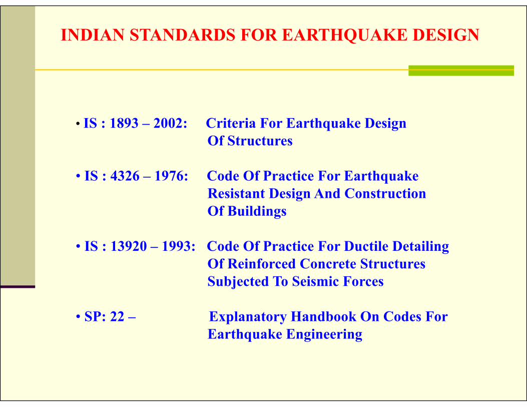
INDIAN STANDARDS FOR EARTHQUAKE DESIGN
• IS : 1893 – 2002: Criteria For Earthquake Design Of Structures
• IS : 4326 – 1976: Code Of Practice For EarthquakeResistant Design And ConstructionOf Buildings
• IS : 13920 – 1993: Code Of Practice For Ductile DetailingOf Reinforced Concrete StructuresSubjected To Seismic Forces
• SP: 22 – Explanatory Handbook On Codes For Earthquake Engineering

MAGNITUDES OF SOME OF THE PAST EARTHQUAKES IN INDIA
1. 1897 – THE ASSAM EARTHQUAKE - M 8.72. 1938 – THE BIHAR-NEPAL EARTHQUAKE – M 8.43. 1950 – THE ASSAM-TIBET EARTHQUAKE – M 8.74. 1967 – THE KOYNA EARTHQUAKE – M 6.55. 1988 – THE BIHAR-NEPAL EARTHQUAKE – M 6.66. 1991 – THE UTTAR KASHI EARTHQUAKE – M6.67. 1993 – THE LATUR EARTHQUAKE – M 6.48. 1997 – THE JABALPUR EARTHQUAKE – M 6.09. 1999 – THE CHAMOLI (U.P) EARTHQUAKE – M 6.810. 2001 – THE BHUJ (GUJARAT)EARTHQUAKE – M 7.9

STRUCTURAL RESPONSE
Structural Response depends on
Input motion
Structural Properties
Uncertainties in Input motion
• When and where the next earthquake
• On what fault ( location)
• On what magnitude
• Effect of travel path on shaking at a distance
• Effect of local geology, topography and soil profile

OBJECTIVES OF EQ RESISTANT ESIGN
Should the structure be designed to withstand
strong shaking without sustaining any damage
Such a construction will be too expensive
It may be more logical to accept some damage in case of strong shaking
However, loss of life must be protected enen in case of strong shaking.

Earthquake Resistant Design Concept
S t r o n g M o t io n Z o n e
Level 1 Maximum Credible Earthquake (MCE)500 Years Return Period2 % Possibility of occurrence in 50 Yrs
Level 2 Design Basis Earthquake (DBE)250 Years Return Period10 % Possibility of occurrence in 50 Yrs

Earthquake Resistant Design Philosophy
Building
should resist minor earthquakes (<DBE) with some non-structural damage
should resist moderate earthquake (DBE) with some structural damage, but without failure
can fail at most severe earthquake (MCE), but with sufficient warning.

SEISMIC ZONE MAP OF INDIA
F=m *a
a = Z*gZ = Zone Factor
m
F

Structures should be able to resist
Resist Minor shaking ( < DBE , Design based EQ)
No damage
Resist Moderate shaking ( DBE )
No structural damage
Some non structural damage
Resist Severe shaking ( MCE, Max. considered EQ)
Structural damage without collapse
DBE – Max. EQ that can be expected to experience at the site
Once during life time of the structure. (DBE generally half of MCE)
OBJECTIVES OF EQ RESISTANT ESIGN

t
Ü
Üg
Ü
t
Üg
Earthquake Accelerogram
Response of the Structure
CONCEPT OF RESPONSE SPECTRUM-1
Find Amax
It is a plot of the peak response (Velocity, Displacement or Acceleration) w.r.t Period of SDOF system for a given Accelerogram.

Üg
Ü
t
Üg
Earthquake Accelerogram
Concept of Response Spectrum -2
Find Response Amax in each case
Ü
1/1
/2/1
fi
ii
T
mkf
T1 T2 T3
a2, maxa3, max
a1, max
T
a, max
For various values of Period of SDOF structures, Find Peak acceleration for the given input earthquake acceleration and plot
Response (acc) v/s Period

0 1 2 3 4 50.0
0.5
1.0
1.5
2.0
2.5 Rock or Hard Soil
Medium Soil
Soft Soil
Sa/
g
Time Period (secs)
Response Spectrum IS : 1893 :2002

METHODS OF FINDING THE EARTHQUAKE FORCES
1. Seismic Coefficient Method
2. Dynamic Analysis
• Response Spectrum Method• Time History Analysis

BASIS OF SEISMIC COEFFICIENT METHOD
VB = m aVB = (W/g) aVB = W (a/g)VB = W Ah
Ah = Basic horizontal seismic coefficientVB = Base shearW = Total weight of the structurea = Acceleration induced at the base during earthquakeg = Acceleration due to gravity

SEISMIC COEFFICIENT METHOD
Assumptions
• Assume that structure is rigid. • Assume perfect fixity between structure and foundation.• During ground motion every point on the structure
experience same accelerations• Dominant effect of earthquake is equivalent to horizontal
force of varying magnitude over the height.• Crudely determines the total horizontal force (Base
shear) on the structure
VB = W Ah

VB = W Ah
During an earthquake structure does not remain rigid, it deflects, thus base shear is disturbed along the height.
Ah is modified to consider the following effects.
Natural period Damping Modal shapes Types of structure and place(zone) Subsoil conditions Importance of the structure
BASIS OF SEISMIC COEFFICIENT METHOD

R
I
g
SZA
WAV
ah
hB
..2
Z=Zone Factor
Ss/g = Spectral Acceleration taken from ResponseSpectrum
I= Importance Factor
R=Ductility / Over-Strength Reduction Factor
CALCULATION OF SEISMIC FORCE-1


Zone Factor & Multiplying Factor for Different Damping
R
I
g
SZA
WAV
ah
hB
..2
Zone factor Z is for MCEFor DBE, it is Z/2

VALUES OF IMPORTANCEFACTOR - I

Response Reduction Factor- R
Sl No Lateral Load Resisting System R
Building Frame Systems
1 Ordinary RC moment Resisting frame (OMRF)2 3.0
2 Special RC moment Resisting Frame (SMRF)3 5.0
3 Steel Frames with
a)Concentric Bracesb)Eccentric Braces
4.05.0
4 Steel Moment Resisting Frame Designed as per SP 6(6) 5.0
Buildings with Shear Walls4
5 Load Bearing Masonry Wall Buildings5
a)Un-reinforcedb)Reinforced with Horizontal RC Bandsc)Reinforced with Horizontal RC Bands and Vertical barsAt corners of rooms and jambs of openings
1.52.53.0
6 Ordinary Reinforced Concrete Shear Walls6 3.0
7 Ductile shear Walls7 4.0
Buildings with Dual Systems8
8 Ordinary Shear wall with OMRF 3.0
9 Ordinary Shear wall with SMRF 4.0
10 Ductile Shear wall with OMRF 4.5
11 Ductile Shear wall with SMRF 5.0
Depends on the perceived seismicdamage performance of the
structure, characterised by ductile or brittle deformation

75.0a h075.0T for RC frame buildings
for Steel frame buildings 75.0
a h085.0T
d
h09.0Ta for all other buildings, moment resisting
frames with Brick In-fill Panels
EMPIRICAL FORMULA FOR CALCULATION OF FREQUENCIES

0 1 2 3 4 50.0
0.5
1.0
1.5
2.0
2.5 Rock or Hard Soil
Medium Soil
Soft Soil
Sa/
g
Time Period (secs)
Response Spectrum IS : 1893 :2002
R
I
g
SZA
WAV
ah
hB
..2

n
1
2ii
2ii
Bi
hW
hWVQ
DISTRIBUTION OF BASE SHEAR
Qi – Design lateral force at floor iWi – Seismic Weight of floor i ( DL + LL)hi - Height of floor i measured from basen - Number of storey in the building
(LL = 30% of Normal Live Load ) < 3 kN/m2)(LL = 50% of Normal Live Load) > 3 kN/m2)

SEISMIC COEFFICIENT METHOD
Distribution of forces along the storey
Frame Forces on storey level Shear distribution
hi
VB
Q4
Q3
Q2
Q1
Q4
Q3
Q2
Q1
Q4
Q3
Q2
Q1
W4
W3
W2
W1
n
1
2ii
2ii
Bi
hW
hWVQ

DAMPING RATIO FOR DIFFERENT TYPES OF STRUCTURES
• STEEL STRUCTURE - 2-5%
•CONCRETE STRUCTURE- 5-10%
•BRICK STRUCTURE - 5-10%
•TIMBER STRUCTURE - 2-5%
•EARTHEN STRUCTURE - 10-30%
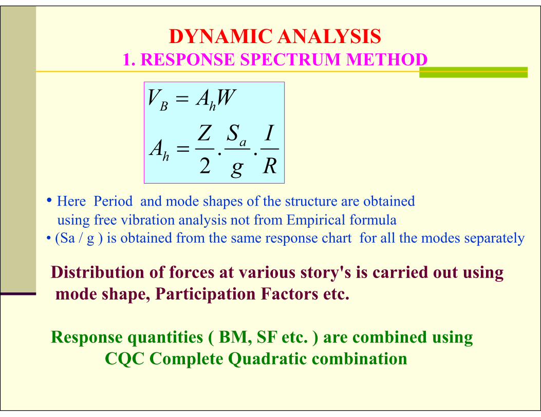
DYNAMIC ANALYSIS1. RESPONSE SPECTRUM METHOD
Distribution of forces at various story's is carried out usingmode shape, Participation Factors etc.
Response quantities ( BM, SF etc. ) are combined using CQC Complete Quadratic combination
R
I
g
SZA
WAV
ah
hB
..2
• Here Period and mode shapes of the structure are obtained
using free vibration analysis not from Empirical formula• (Sa / g ) is obtained from the same response chart for all the modes separately

MODE SHAPES OF OSCILLATION OF BUILDINGS
i
Mode 1 Mode 2 Mode 3Frame
Lateral forces are found by superimposition of the Forces resulting from each mode

Obtain the design parameters by giving the actual Earthquake excitation
DYNAMIC ANALYSIS2. TIME HISTORY ANALYSIS
TimeAcc
eler
atio
na(t)
Time
Dis
plac
emen
t

Over-riding of Response Parameters Computed From Analysis
Dynamic analysis may be performed either by the timehistory method or by the response spectrum method.
If base shearVB < VB
1
R. S. Method Seismic coefficient method
All response quantities obtained in RSM ( for examplemember forces, displacements, storey forces, storey shears
and base reactions ) shall be multiplied by VB1 / VB .

COMPARISION OF PSEUDO STATIC ANALYSIS AND DYNAMIC ANALYSIS
Q3
Q2
Q1
a(t)
Obtain Q1—Q3 using SCM or RSM•Analyse the frame to obtain designBM & SF in SCM
• Analyse the frame to obtain BM & SFResponses are combined as per CQCmethod in RSM
Directly we get design BM & SF inDynamic analysis.
at

CHOICE OF METHOD FOR MULTISTORIED BUILDING

PARTIAL SAFETY FACTOR
MATERIALS
•CONCRETE - 1.5•STEEL - 1.15
LOADS
• 1.5(DL + LL)• 1.2(DL + LL EQ/WL)• 1.5(DL EQ/WL)• 0.9DL 1.5EQ/WL
LL = 25% OF THE NORMAL LIVE LOAD

DESIGN MOMENTS IN MEMBERS-1
1. 1.5(DL + LL)
2. 1.2(DL + LL + EQ/WL)3. 1.2(DL + LL - EQ/WL)
4. 1.5(DL + EQ/WL)5. 1.5(DL - EQ/WL)
6. 0.9DL + 1.5EQ/WL7. 0.9DL - 1.5EQ/WL
A BC

DESIGN MOMENTS IN MEMBERS-2 ( Ex.)
A BC
LoadingEnd A Cent- C End-B
Loading-1 -60 +40 -70
Loading-2 +25 +35 -85
Loading-3 -80 +30 +20
Loading-4 +10 +35 -80
Loading-5 -70 +35 -15
Loading-6 +15 +20 -65
Loading-7 -60 +20 +10
Design mom. -80/+25 +40 -85/ +20


