ReferencePUBLICATIONS
NBSIR 85-31
Methods to Calculate theResponse Time of Heat andSmoke Detectors Installed BelowLarge Unobstructed Ceilings
NAT'L INST. OF STAND & TECH
AlllDb 034^34
67
David D. Evans
David W. Stroup
U.S. DEPARTMENT OF COMMERCENational Bureau of Standards
National Engineering Laboratory
Gaithersburg, MD 20899
February 1985
issued July 1 985
~-QC-
100
• 1156
Prepared for the Sponsor:
I.S. Nuclear Regulatory CommissionWashington, DC 20555
85-3167
1985
national bureauOF STANDARDS
I ’"NARY
NBSIR 85-3167\ • *
METHODS TO CALCULATE THERESPONSE TIME OF HEAT ANDSMOKE DETECTORS INSTALLED BELOWLARGE UNOBSTRUCTED CEILINGS
David D. Evans
David W. Stroup
U.S. DEPARTMENT OF COMMERCENational Bureau of Standards
National Engineering Laboratory
Gaithersburg, MD 20899
February 1985
Issued July 1985
Prepared for the Sponsor:
U.S. Nuclear Regulatory CommissionWashington, DC 20555
U.S. DEPARTMENT OF COMMERCE, Malcolm Baldrige, Secretary
NATIONAL BUREAU OF STANDARDS, Ernest Ambler. Director
TABLE OF CONTENTS
Page
Abstract 1
1.0 Introduction 1
22.0 Detector Response to t - Fires 4
3.0 Detector Response to Arbitrary Fires 9
4.0 Smoke Detector Response 11
5.0 Summary 15
6.0 Acknowledgement 15
7.0 References 15
8.0 Notation 17
Appendix A - DETACT - T2 CODE 19
1) Example Calculation2) Program Listing
Appendix B - DETACT - QS CODE 32
1) Example Calculation2) Program Listing
i
METHODS TO CALCULATE THE RESPONSE TIME OF HEAT AND SMOKE
DETECTORS INSTALLED BELOW LARGE UNOBSTRUCTED CEILINGS
Abstract
Recently developed methods to calculate the time required for ceiling
mounted heat and smoke detectors to respond to growing fires are reviewed. A
computer program that calculates activation times for both fixed temperature
and rate of rise heat detectors in response to fires that increase in heat
release rate proportionally with the square of time from ignition is given.
This program produces nearly equivalent results to the tables published in
Appendix C, Guide for Automatic Fire Detector Spacing, (NFPA 72E, 1984). A
separate method and corresponding program are provided to calculate response
time for fires having arbitrary heat release rate histories. This method is
based on quasi-steady ceiling layer gas flow assumptions. Assuming a constant
proportionality between smoke and heat released from burning materials, a
method is described to calculate smoke detector response time, modeling the
smoke detector as a low temperature heat detector in either of the two
response time models.
1. INTRODUCTION
Studies of the response of heat detectors to fire driven flows under
unconfined ceilings have been conducted since the early 1970's [1, 2, 3, 4],
Results of these largely experimental studies have been used to develop corre-
lations of data that are useful under a broad range of fire conditions and
building geometries. These correlations have been used to construct engineer-
ing methods to determine heat detector spacing, sprinkler response time, ml
smoke detector alarm times for industrial buildings where large undivided
1
ceilings over storage and manufacturing facilities are common. The method for
calculation of heat detector spacing has been adopted by the National Fire
Protection Association (NFPA) as an alternate design method published in the
standard NFPA 72E, 1984 [5].
Although the NFPA heat detector spacing calculation is a well documented
method, it is not in a convenient form for use by the Nuclear Regulatory
Commission (NRC) in evaluating the response characteristics of existing
systems for two reasons. 1) Currently, the only available form of the infor-
mation is the tabular form published in the NFPA 72E standard. An analytic
form or computer subroutine that produced equivalent answers would be more
flexible and of greater use to NRC. 2) The published tables are organized to
look-up spacing requirements for a given response time. In the evaluation of
existing systems, the opposite problem is of interest - for a given spacing
and detector determine the response time.
As part of this study, the basis for the calculation method published in
Appendix C of the NFPA 72E standard was determined. Alternative correlations
of the same experimental data that are the basis for the tables in Appendix C
of the NFPA 72E standard were used to construct a FORTRAN program (DETACT-T2
Code) to evaluate the response time of existing heat detector systems. Using
the program, calculated values for response time agree to within 5 percent of
those published in the tables contained in Appendix C of the NFPA 72E
standard. Although this calculation method is the most firmly based of those
to be discussed in this report, it is restricted to application in which the
fire to be detected increases in energy release rate proportionally with the
square of time from the ignition.
2
separate program (DETACT-QS Code), written in PC BASIC, is capable of
evaluating detector response for a fire with an arbitrary energy release rate
history. The only restriction is that the energy release rate must be repre-
sented as a series of connected straight lines, the end points of which are
entered as user input data. Inaccuracies may be introduced in the analysis of
rapidly varying fires because this code uses a quasi-steady approximation for
the fire driven gas flow. This means that changes at the fire source
immediately affect the gas flows at all distances from the fire. In reality,
time is required for the gases to travel from the fire to remote locations.
Generally, fire driven flows have a velocity the order of one meter per
second. Thus a quasi-steady analysis for locations close to the fire will
only be in error by a few seconds, while remote locations can be delayed by
tens of seconds. Keeping this approximation in mind, this program represents
the most flexible of available methods but has not been tested against experi-
mental data.
Both of the codes discussed above analyze detector response at
installation sites under large unconfined ceilings. For smaller compartments,
in which confining walls will cause a layer of fire products to accumulate
under the ceiling, hence submerging the ceiling-jet flow before the heat
detector can respond, different calculations are necessary. The problem of
analyzing the response of heat detectors or sprinklers in a two-layer
environment (warm fire products over cool air) has been studied [6], but no
single code has been produced to facilitate analysis. This class of problem
will not be discussed in this report.
3
Analysis of smoke detector response is currently performed by
approximating the smoke detector as a low-temperature zero-lag-time heat
detector. Selection of the response temperature corresponding to a given
detector sensitivity also depends on the relative proportion of "smoke" and
energy released by the burning fuel. Test data of gas temperature rise at the
time of smoke detector alarm is presented in this report. An alternative
approximate method is given to determine this same temperature rise by using
fuel smoke and energy release rate measurements obtained in a laboratory scale
apparatus developed by Tewarson [7].
2. DETECTOR RESPONSE TO t 2 - FIRES
Appendix C of the NFPA 72E standard [5], "Guide for Automatic Fire
Detector Spacing," contains methods to determine the required heat detector
spacing that will provide alarms to growing fires before the fire has grown to
a user specified energy release rate. Tables provide information to evaluate
different fire growth rates, ceiling heights, ambient temperatures, detector
alarm conditions (fixed temperature or rate of rise), and detector thermal
time constant. The tables reflect the extensive experimental studies and
mathematical fire modeling performed by Heskestad and Delichatsios at Factory
Mutual Research Corporation [3, 4].
Beyler [8] uses a different correlation of Heskestad and Delichatsios*
data than was used to produce the tables in NFPA 72E Appendix C to obtain an
analytical expression for the gas flow temperature and velocity produced under
ceilings that can be used to evaluate heat detector response. Beyler's solu-
tions are limited to evaluation of fires that increase in energy release rate
4
proportionally with the square of time from ignition. This class of fire is
commonly referred to as a "t-squared-f ire. " Briefly, the problem of the heat
detector response is solved using analytic solutions for the time dependent
temperature of the detector sensing element up to the point when it is heated
to the specified alarm conditions. The model for the detector sensing element
temperature is based on a convective heat transfer process. Characterization
of the thermal response of heat detector and sprinkler thermal sensing
elements is discussed by Heskestad and Smith [9], and Evans [10]. The first
order differential equation that describes the rate of temperature increase of
the sensing element is [6]:
dTs
dt
,1/2
RTI( 1 )
The notation for all equations is given in the notation section. The value of
RTI (Response Time Index), a measure of the thermal time constant of the
detector, is determined by testing [9]. Values of the time-dependent gas
temperature and velocity are obtained from the following correlations [8].
*AT
2= 0 for t* < (t*)
f
AT* = {[t* - 0.954(1 + r/H)] / [0. 188 + 0.313 r/H]}4/3
for t* > (t*)f
(t2 ) f
= 0.954 [1 + r/H] ( 2 )
* -0.63 * 1/2U2 = 0.59 [r/H]
U * bJ[AT
2 ]
1/Z
where
5
U2
= U/[A Ct H]1/5
AT* = AT/[A2/5
(Ta)/g) a
2/5H~
3/5]
* _ wrA_1/5 '1/5 h4/5 1t2 = t/[A a H
i
A = g/(c T p )
P 00 00
AT = T - T
a = t /Q
The solutions to equation (1) for detector sensing element temperature, T_,
and rate of temperatue rise, dTg /dt, in response to the t^ - fire with growth
rate specified by the value of a are from Beyler [8] as follows:
ATg = (AT/AT*) AT* [1 - (1 - e
Y)/Y] (3)
dTs
(4/3)(4T/4T*)( 4T*)1/ '‘
dt” * (^ “ e
)^ ^
(t/t2)(0.188 + 0.313 r/H)
where
1/24T^
RTI(0.188 + 0.313 r/H)
assuming that ATg
= 0 initially. T and U in equation 1 are obtained from the
correlations in equation set (2) for AT2
and U2
respectively. Equations 3 and
4 were programmed into a user interactive FORTRAN code called the DETACT-T2
6
Code. This code solves for the time required to reach a specified positive
value of AT or dT /dt representing detector alarm. Details of the DETACT-T2s s
Code use, a worked example, and program listing are given in Appendix A.
Briefly for a fixed temperature detector, the user enters values for:
Ambient air temperature
Detector response temperature or rate of temperature rise
Detector RTI
Fuel to ceiling distance
Radial distance of detector from the fire plume axis
Fire growth rate constant a (for t^ fires)
Outputs of the code are the time to detector response and fire energy
release rate at that time.
In Appendix A, use of the DETACT-T2 Code to calculate the response time
of a fixed temperature detector is demonstrated in a worked example using the
following program inputs:
Ambient air temperature 21.1°C (70°F)
Detector response temperature 54.44°C (130°F)
Detector RTI
Fuel to ceiling distance 3.66 m (12 ft.)
Radial distance of detector fromaxis of fire 2. 16 m (7.07 ft.
)
11.71 J/s 3 (0.0111 BTU/s 3)Fire growth rate constant
7
The calculated response time using the DETACT-T2 Code is 298 seconds and
corresponding fire energy release rate is 1.04 MW (986 BTU/s). This same fire
and detector combination can be seen in the table C-3-2. 1.1(e) in Appendix C
of NFPA 72E [5], (in the table notation, threshold fire size 1000 BTU/s, fire
growth rate, medium; DET TC = 300 As, AT = 60°F, ceiling height = 12 Aft,
installed spacing in the body of the table 10ft). All values in table C-3-
2.1.2(e) [5] are for detector response times of 300 seconds. This is in
agreement with the 298 s calculated with the DETACT-T2 Code given in Appendix
A of this report.
Eleven other randomly selected combinations of fires and detectors were
calculated using the DETACT-T2 Code and results compared to table values in
Appendix C of NFPA 72E [5]. Of these cases the greatest deviation was 7.5%
and least was 0.17%.
Use of the DETACT-T2 Code has two main advantages over the tables in
Appendix C of NFPA 72E [5]. One is that the code is specifically designed to
evaluate existing facilities. The other is that any t - fire growth rate can
be analyzed. The tables in Appendix C of NFPA 72E [5] contain only three
different fires. At present, an NBS special publication is being prepared
containing tabular results with the same information as those in the NFPA 72E,
Appendix C [5], but recast into a form useful for evaluation of existing
facilities. This publication "Evaluating Thermal Fire Detection Systems," by
Stroup, Evans, and Martin should become available in 1986.
8
3. DETECTOR RESPONSE TO ARBITRARY FIRES
The DETACT-T2 Code is useful for evaluating the response of specified
detectors to t2 - fire growth rates. In some cases a fire of interest does
not follow an energy release rate that is proportional to the square of time
from ignition. For these cases use of the DETACT-T2 Code to evaluate the
responses of detector systems is inappropriate.
To evaluate detector response to an arbitrary energy release rate
history, an assumption of quasi-steady gas flow temperatures and velocities is
made. With this assumption, correlation for ceiling-jet temperatures and
velocities obtained from experiments using steady fire energy release rate
sources can be used to evaluate growing fires. The growing fire is repre-
sented in the calculation as a series of steady fires with energy release
rates changing in time to correspond to the fire of interest.
Correlations of ceiling-jet temperatures and velocities from experiments
using steady fire sources have been published by Alpert [1]. Recast into
metric form they are:
for r/H < 0.18
U = 0.95 (Q/H) 1/3 for r/H < 0.15 (5)
for r/H > 0.18
U = 0.2 Q1/3
H1/2
/ r5/6
for r/H > 0. 1
5
9
where the metric units are T[°C], U[m/s], Q[kW], r[m], H[m].
A computer code to perform the integration of equation 1, the
differential equation for detector sensor temperature, using the quasi-steady
fire driven flow approximation and Alpert's correlations from equations in 5,
is listed in Appendix B. This code, called the DETACT-QS Code, is written in
PC BASIC. The code requires user input similiar to the DETACT-T2 Code in
Appendix A, with the one exception that the fire energy release rate is speci-
fied as a series of time, energy release rate data pairs.
The same fire and detector case used as an example of execution for the
DETACT-T2 Code was evaluated using the DETACT-QS Code. The example inputs and
results are given in Appendix B. The fire was input as time, energy release
orate pairs at intervals of 5 seconds to match the t - fire with a = 11.7105
W/s . Other parameters were maintained the same. The resulting predicted
detection time using the DETACT-QS Code was 313 seconds with the corresponding
fire energy release rate at detection of 1147 kW. Remember that with the
DETACT-T2 Code the calculated time of detection was 298 seconds with fire
energy release rate at detection of 1040 kW. This example was chosen to
demonstrate specifically that there will be differences between the two
methods even in the evaluation of the same fire. The quasi-steady fire
analysis on which the DETACT-QS Code is based has the advantage that arbitrary
fire energy release rates can be input as a data set.
10
4. SMOKE DETECTOR RESPONSE
Both of the heat detector response models discussed are based on
predictions of the temperature and velocity of the fire driven gas flow under
the ceiling and models of the heat detector response. The same calculations
could be used to predict smoke detector response given a relationship between
smoke concentration and temperature rise in the fire driven gas flow and the
response characteristics of the smoke detector.
The response characteristics of smoke detectors are not as well
understood as thermal detectors. Smoke detector alarm conditions depend on
more than smoke concentration. Smoke particle sizes and optical or particle
scattering properties can affect the value of smoke concentration necessary to
reach alarm conditions. For thermal detectors, measured values of RTI
characterize the lag time between gas temperature and sensing element tempera-
ture. For smoke detectors there is no analogous method to characterize the
lag time between gas flow smoke concentration and the smoke concentration
within the sensing chamber. In the absence of understanding of the many
processes affecting smoke detector response, a smoke detector will be considered to
be a low temperature heat detector with no thermal lag, i.e. RTI = 0. The
analogy between smoke obscuration in the gas flow and temperature rise will be
developed in order to determine the corresponding temperature rise to use as a
model for a smoke detector known to alarm at a given smoke obscuration.
Similarity between temperature rise and smoke concentration will be
maintained everywhere within a fire-driven flow if the energy and smoke
continuity equations are similar. For the case of constant cp
, k, and I) thosr
equations are:
11
:- k V
2AT = O"
'
p dt( 6 )
2- p D V Y
sm
t » ?
( 7 )
If the Lewis number k/pc^D = 1, then the ratio of temperature rise to
smoke concentration can remain constant throughout the fire driven flow, if
exchanged with the flow. Reactions in the flame over the burning fuel will
determine the ratio of temperature rise to smoke concentration throughout the
flow. Other energy exchanges in normal fire flows, convection to cool room
boundaries, and radiation from smokey gases decrease the ratio of temperature
rise to smoke concentration because energy is extracted from the flow without
a proportional decrease in smoke concentration. Mixing of hot combustion
products with cool smokey gases that may accumulate in an enclosure also
decrease the ratio of temperature rise to smoke concentration because smoke
mass is added to the flow without a proportional increase in energy. For fire
driven flows in which the effects that alter the ratio of temperature rise to
smoke concentration are not significant, the response of smoke detectors may
be calculated as if it were a fixed temperature heat detector. The tempera-
ture rise necessary for alarm of this substitute heat detector is calculated
from the product of smoke concentration needed to alarm the smoke detector and
the ratio of temperature rise to smoke concentration produced by the burning
material.
Generally the sensitivity of smoke alarms are given in terms of the
amount of obscuration by the smokey flow that is necessary to produce an alarm
and not directly in smoke concentration. The more sensitive the smoke
detector the smaller the amount of obscuration needed to alarm.
12
The obscuring ability of a smoke laden gas flow is measured by the
attenuation of a light beam. The measure of the attenuation is the optical
density per unit beam length, OD, [3]
OD = (log1Q
“|)/L (8)
By testing, Seader and Einhorn [11] found that the attenuating abilities of
smokes produced from many different materials undergoing flaming combustion
were similar. For flaming combustion they found that the optical density per
unit length was proportional to the mass concentration of "smoke" in a gas
flow as:
OD = 3330 Cs (9)
where OD is optical density per meter and Cg
is smoke mass concentration in
kilograms per cubic meter.
The ratio of temperature rise in a fire driven flow to smoke
concentration may be recast in terms of optical density using equation 9 as
:
AT = pAT = 3330pATY C ODs s
( 10 )
Under the assumption discussed at the beginning of this section, this
. " ' .» » '
ratio will be equal to the ratio Q ' Cpms
* The la8t ratio may be approxi-
mated by a volume average over the combustion region so that
3330 DATOD
c mP s
13
or
OPAT
3330pc mP s
•
Q
( 11 )
As an example, literature values for oak wood may be used to obtain a
representative value. For oak
Q = 7600 kJ/kg fuel consumed per unit time
m = 0.017 kg smoke/kg fuel consumed per unit times
air Cp = 1 kJ/kg °C
air p = 1.165 kg/m^ at 30°C
From equation (11) 7^7 = 8.68 x 10 ^ (m°C) *.
Ai
Heskestad and Delichatsios [3] have reported representative optical
density per meter for smoke detector alarm and corresponding temperature rise
in the gas flow. For wood crib (unknown type) fires, the ratio of these
-3values was OD/aT = 1.2 x 10 [l/m°C]. This is the same order of magnitude as
the number calculated in the analysis given above and may be representative of
the expected accuracy given no knowledge of wood type. Heskestad and
Delichatsios [3] report that an ionization detector will alarm in response to
a wood fire at OD = 0.016 1/m.
Using the OD/aT value for wood of 1.2 x 10-^(m°C)“^ the corresponding
change in gas temperature would be 13°C, (0.016/1.2 x 10“^). For the purpose
of response time calculation using the heat detector models, this ionization
smoke detector would be represented as a low temperature heat detector
alarming at 13°C above ambient for a wood fire.
[ 12 ]
[ 12 ]
14
Other measurements of the ratio OD/aT are obtained for burning materials
in a laboratory scale apparatus developed by Tewarson [7]. Values for a large
number of plastics and wood under many environmental conditions are given by
Tewarson [12].5.
SUMMARY
Two methods have been presented to calculate the response of heat
detectors installed under large unobstructed ceilings in response to growing
fires. Smoke detector response is calculated using the same thermal calcula-
tions by approximating the smoke detector as a low temperature, zero lag time
thermal detector.
6.
ACKNOWLEDGMENT
The authors are grateful to Mr. Doug Walton for coding DETACT-QS version
1.1 for exection in PC BASIC.
7.
REFERENCES
1. Alpert, R. L. , Calculation of response time of ceiling-mounted fire
detectors. Fire Technology , 8, 1972, p 181.
2. Alpert, R.L.,
TXirbulent ceiling-jet induced by large-scale fires,
Combustion Science and Technology , 11, 1975, p 197.
3. Heskestad, G. and Delichatsios , M. A. ,Environments of fire detectors
phase 1; Effects of fire size, ceiling height and material, Volume II -
Analysis. Technical Report Serial No. 22427, RC 77-T-ll, Factory MutualResearch Corporation, Norwood Massachusetts 02062, 1977.
4. Heskestad, 6, and Delichatsios, M. A. ,The initial convective flow in
fire, Seventeenth Symposium (International) on Combustion,
The CombustionInstitute, Pittsburgh, Pennsylvania, 1978, pp 1113-1123.
15
5. Standard on Automatic Fire Detectors, NFPA 72E-1984, Appendix C, NationalFire Protection Association, Batterymarch Park, Quincy, MA, 02269.
6. Evans, D.D., Calculating Sprinkler Actuation Time in Compartment, to be
published in Fire Safety Journal, 1985.
7. Tewarson, A., and Pion, R.,
"A Laboratory-Scale Test Method for theMeasurement of Flammability Parameters, FMRC serial No. 22524, FactoryMutual Research Corporation, Norwood, Mass. 02062, Oct 1977.
8. Beyler, C.L.,A design method for flaming fire detection, Fire Technology,
20, 4, 1984, p 5.
9. Heskestad, G.,
Smith, H. , Investigation of a New Sprinkler SensitivityApproval Test: The Plunge Test FMRC Technical Report 22485, FactoryMutual Research Corporation, Norwood, Mass. 02062, 1976.
10. Evans, D. D. , Madrzykowski, D.,Characterizing the Thermal Response of
Fusible-Link Sprinklers, NBSIR 81-2329, U. S. Department of Commerce,
National Bureau of Standards, Washington, D.C. 20234, (1981).
11. Seader, J. and Einhorn, I., ’’Some Physical, Chemical, Toxicological, and
Physiological Aspects of Fire Smokes”, Sixteenth Symposium(International) on Combustion , The Combustion Institute, Pittsburgh,Penn. 1976, pp 1423-1445.
12. Tewarson, A., Physico-Chemical and Combustion/Pyrolysis Properties of
Polymeric Materials. FMRC J. I. OEONG. RC, Factory Mutual ResearchCorporation, Norwood, Mass 02062, Nov. 1980, p 27.
16
8. NOTATION
A
cp
Cs
D
g
H
I
Xo
L
ft”'s
OD
0
Q* ' *
r
RTI
t
*t2
, * V
( t2 )f
T00
T
Ts
AT
AT.
g/( Cp
Too Poo }
specific heat capacity of ambient air
smoke mass concentration
effective Binary diffusion coefficient
acceleration of gravity
vertical distance from fuel to ceiling
light intensity
initial Light intensity
light beam length
smoke gas mass production rate per unit volume
optical density per unit length (see eq. 8)
fire energy release rate
energy release rate per unit volume.
radial distance from fire axis to the detector
response time index, the product of the detector thermal timeconstant and the square root of the gas speed used in the test
to measure the time constant [9].
time
dimensionless time t/[A
dimensionless time for time delay for gas front travel.
ambient temperature
gas temperature at detector location
temperature of detector sensing elements
T - T00
dimensionless temperature difference AT/[A^^(T^/g) a5
)
gas speed at the detector location
dimensionless gas speed U/[A a
17
local ratio of smoke mass to total mass in flow
proportionality constant for t^- fire growth = Q/t
ambient air density
APPENDIX A - DETACT-T2 CODE
FORTRAN Program to Calculate
2Detector Response to t - Fires
1) Example Calculation
2) Program Listing
19
APPENDIX A. DETACT-T2 CODE
A FORTRAN Program to Calculate Detector Response to X?- ~ Fires
This appendix describes the theory and use of a computer program which
determines the response of fixed temperature and rate of rise heat detectors
2to fires with energy release rates described by the expression Q = at . The
program is designed for use in evaluating detectors installed at known
spacings.
The activation time of a given detector is a function of fire growth
rate, ceiling height, detector spacing, detector activation temperature,
ambient temperature, and detector response time index (RTI). The program
prompts the user to provide this information. These input data are converted
to a dimensionless form for use in the calculations. Equations for the
activation time of a fixed temperature detector and a rate of rise detector
are set up. The two equations are then solved using a Newton-Raphson
technique. Once the activation times are known, the lire energy release rates
at those times are calculated. Finally, the results for each detector type
are printed as well as some appropriate input data.
In the following example, input prompts from the
printed in all capital letters while user responses cir
(where possible) and proceed ed by the character ">".
computer program are
e printed in lower case
20
EXAMPLE
Calculate the activation times for fixed temperature and rate of rise
heat detectors installed, using a 3.05 meter spacing, in an area with a
ceiling height of 3.66 meters. The detectors have an RTI of 370.3 (m-
sec)^^. The detector activation temperature is 54.4°C, and the activation
rate of rise is 8.33°C/min. Ambient temperature is 21 °C.
ENTER 1 FOR ENGLISH UNIT INPUT
2 FOR METRIC UNIT INPUT
>2
ENTER THE AMBIENT TEMPERATURE IN DEGREES C.
>21
ENTER THE DETECTOR RESPONSE TIME INDEX (RTI) IN (M-SEC)**1 /2.
>370.3
ENTER THE DETECTOR ACTIVATION TEMPERATURE IN DEGREES C.
>54.4
ENTER A DETECTOR RATE OF RISE IN DEGREES C/MIN.
>8.33
ENTER THE CEILING HEIGHT IN METERS.
>3.66
ENTER THE DETECTOR SPACING IN METERS.
>3.05
ENTER: S FOR SLOW FIRE GROWTH RATE
M FOR MEDIUM FIRE GROWTH RATE
F FOR FAST FIRE GROWTH RATE OR
0 FOR OTHER
>m
21
RESULTS:
CEILING HEIGHT = 3.66 METERS ( 12.0 FEET)
DETECTOR SPACING = 3.05 METERS ( 10.0 FEET)
DETECTOR RTI = 370.3 (M-SEC)**l/2 ( 670.8 (FT-SEC)**1 /2
)
FIRE GROWTH CONSTANT = .1171+002 WATTS/SEC**2)
(.1111-001 BTU/SEC**3)
FOR TEMPERATURE ACTUATED DETECTOR:
ACTIVATION TEMPERATURE = 54.4 DEGREES C (129.9 DEGREES F)
TIME OF ACTIVATION = 297.88 SECS
HEAT RELEASE RATE = .1038+007 WATTS (.9840+003 BTU/SEC)
FOR RATE OF RISE ACTUATED DETECTOR:
ACTIVATION RATE OF RISE = 8.33 DEGREES C/MIN
(14.99 DEGREES F/MIN)
TIME OF ACTIVATION = 182.75 SECS
HEAT RELEASE RATE = .3908+006 WATTS (.3704+003 BTU/SEC)
22
The results show that the heat detector would activate approximately 298
seconds after the fire reaches a flaming state. The heat release rate at this
time would be 1038 kilowatts. A rate of rise detector would activate at about
183 seconds with a corresponding heat release rate of 391 kilowatts.
If English units had been selected, the input requests would have called
for data in English units instead of metric units.
The program is written in ANSI 77 FORTRAN. A PC BASIC version is being
coded. Each is in a form which makes it easy to incorporate into existing
computer fire models as a subroutine.
23
****** PROGRAM DETACT-T? ******
PROGRAM DEI ACT
C
c **************** *********** *******************************************c
C DETACT-T2 CODFC
C A FORTRAN pRGGR
A
m FOR CALCULATING DETFCTOR RESPONSEC TO TIME SQUARED FIRES.C
£**** 4 «****** 4 ******* ************ ************************* ****** *******C
Q**************** ** ** ************ **************************************c
C THIS IS A PROGRAM FOR CALCULATING ACTIVATION TI*E AND HFAT
C RELEASE RATE FOR A GIVEN DETEC1CR. iHE pROGRAw CALCULATES RESULTSC FOR BOTH TEMPERATURE AND RATE OF RISE ACTUATED DETECIORS. T HEC PROGRAM REGIURES DATA DFSCRIBING THE DETECTCR, ROOM, AND F IPE
C CHAR ACT ERIST ICS .
C
C PROGRAM WRITTEN BY P • U. STROUP 1/4/85C FINAL REVISION 1/9/85C
£ 4644 * 4 * 644*44444 ******************************************************c
C====> VERSION 1.0 <==================================s=sC
C INPUT:C J - UNITS CODE (1 OR 2 >
C 1 ~ INFUT DATA IN ENGLISH UNITSC 2 - INPUT DATA IN METRIC UMTSC IAMB - AMBIENT TEMPERATUREC R 1 I - DETECTOR RFSPONSF TIME INDEXC TACT - DETECTOR ACTIVATION TEMPERATUREC ROR - DETECTCR ACTIVATION RATE OF RISEC HF - C EILIN G HE IGHTC 2 F - DETE CT CR S PAC INGCM - GROWTH FACTOR CODE, CHARACTER VARIABLE (S, M, F, OR 0)
C ALPHA - FIRE GROWTH RATE FACTORC II fl = 0, ALPHA SHOULD CONTAIN THe GROWTH FACTORR TO BF USFD.cr
IF M <> 0, ALPHA MAY BE SET TO ZERO.L
c OUTPUT:c T T IME OF ACTIVATION FOR A TEMPERATURE DETECTORc QD HEAT RELEASE RATE AT TIME OF ACTIVATION, T
c TR T IME OF ACTIVATION FOR R A 1
E
OF RISE DETECTORc Q DR HEAT RELEASE RATE AT TIME OF ACT IV AT TONt T R
c I ERR - ERROR CODE (0 OR 1)c 0 - SU ccrs S FULc 1 - UN SU CC ESS FULC
E*************************************,***.****************************C
CHARACTER M
DATA IRTT Y, IWTT Y/5 ,6/DATA G E ,C PE , R HO F / 3 2 . 2 t C. 2 4 t 0. 07 35 /
DATA GM, C PM ,R HO M/9. P,1.CC35 , 1.1768/I E R R= 0
24
PROGRAM DE1ACT-1? ******
WRITE (IW1T Y, 10)
10 FORMAT f' ENTER: 1 FOR ENGLISH UNIT I N F ti1 '/ T9 , ' ? F OP METRIC UNIT I
RNPUT')READ ( I R 1 T Y ,*) J
IF (J.EQ.1) THENWRITE (IWTTY,?0)
20 FORMAT (' ENTER THE AMBIENT TEMFERATUR6 IN DEGREES F.')READ < IR1TY ,*) T AMBWRITE OWTTY t 30)
30 FORMAT (' ENTFR THE DETECTOR RESPONSE TIME INDEX (R7I) IN (FT-SEC)R**1/2.'>READ < IRTTY ,*) RT I
IF (RT I. LT. C. 000001) RTI=0. 000001RTI R=R1IWRITE (IWIT Y , 40 )
40 FORMAT (' ENTER THE DETECTOR ACTIVATION TEMPERATURE IN DEGREES F.
'
f )
READ (IRTTY,*) TACTWRITE (IWTTY,50)
50 FORMAT (' ENTER A DETECTOR RATE OF RISE IN DEGREES E/M IN. ^)
RFAD (IRTTY ,* ) RORWRITE (IWTTY.60)
60 FORMAT (' ENTER THE CEILING HEIGHT IN FEET.')READ (IRTTY ,*) HfWRITE (IWTT Y,70 )
7 C FORMAT (' ENTER THE DE1ECT0R SPACING IN FEET.')READ (IRTTY ,*) ZfWRITE (IWTT Y f 80 )
80 FORMAT (' ENTER: S FOR SLOW FIRE GROWTH RATE'/8 ' M FOR MEDIUM FIRE GROWTH RATE'/8 ' F FOR FAST FIRE GROWTH RATE OR'/8 ' 0 FOR OTHER ')
READ ( IR T TY ,410 ) M
IF ((M.E W. ' s'). OR . CM .EG . 'S ')) ALPHA =0 .0C27777PIF < < M.EO in'). OH . (M.E W. 'M ')) AL PH A =0 . 0 1 1 1 1 1
1
IF ((M.ECi.'f').OR.(M.EQ.'F')) AL PH A =Q .0^44445IF (M.NE .'0') GO 7 C 100WRITE (IwTTY,90)
90 FORMAT (' ENTER THE FIRE GROWTH RATE CONSTANT (ALPHA) IN PTU/SFc/SEEC/SEC .'
)
READ (IRTTY ,*> ALP HA
TOO CONTINUEELSEWRITE (IWTT Y, 11 0)
110 FORMAT (' EMFR THE AMBIENT TEMPERATURE IN DEGREES C.')READ (IRTTY,*) TAMEWRITE Own Y , 12 0)
1 20 FORMAT (' ENTER THE DETECTOR RESPONSE TIMF INDEX (RTI) TN <»-$£()£* 1 / 2 .' )
READ URT1Y ,*) RT I
IF (RT I. LT. C. 000001 ) R1I=0. 000001R 1 I R=RT
I
WRITE (IWTT Y, 130)1 3 C FORMAT (' ENTER THE DETECTOR ACTIVATION 1FMPERA TURE IN ffU'f r C.'
R )
read < irt ty ,*) t actWRITE (IWTT Y, 14 G)
140 FORMAT (' E M pR A DETECTOR RATE OF PISE IN DEGREES C/«IN'.')
25
****** pRoGRAp DETACl-T? ******
READ (IR 1 TY ,*) RORWRITE (IWll Y, 15 C)
150 FORMAT (' EN1FR THE CEILING HEIGHT IN METERS.')READ (1RTTY ,*) H
F
WRI TE (IWTT Y , 1 60)
160 F OR PA 7 (' EMFR THE DETECTOR SPACING IN METERS.')READ ( IRTTY ,*) Z F
WRITE (IWTT Y, 80)READ < IRT TY ,A10 ) M
IF ((M.E G • ' s'). OR . CM.EQ.'S')) AL PH A = 2 . 9 3C5 5 55 5
6
IF ((M.EG.'ir').OR.(M.FG.'M'>> AL PH A = 1 1 . 7222 222 2
IF ((M.FG.'f ').OR.(M.EG.'F')) ALPHA =A6 . 8886889IF (M.NE .'0') GO T C 180WRITE (I*TTY,17C)
170 FORMAT (' ENTER THE FIRE GROWTH RATE CONSTANT (ALPHA) IN VATT/SEc'8SEC .' )
READ (IRTTY,*) ALP M
A
180 CONTINUEEND IF
C
£ ************************ calculations *****************************c
R = C . 5* SORT ( ? • )* 2 F
RCH=R/ HF
ROR = RO R/60
•
IF (J.EQ.1) THEN1 AMB=T AMfcj+4 60 .
1AC T = 1ACT + 460.A=GE/(CPE*T AMP* RHOE)G = 6 E
ELSET A MB = T A MB + 2 7 3 •
T AC T = TAC T+2 73 .
A=6M/ (CPK*1 AMP*RH0M*10C0«>G=GMEND IF
T0TS2=A**(-1./5.)*ALPHA**(-1./5.)*HF**(A.Z5.)DL10DL=A ** ( ?• /5 •)* (TAMB/G)* ALPHA** (2. /5 .)*HF** (-3 • / 5 •
)
U0US2 = A**(1 ,/5.)*ALFHA**(1. /5.)*HF**(1./5.)DE LTD = TA CT- T A MB
IF (R0H.GT.0.3) THENUOD LT H = 0 . 59 *R OH * * C - 0 .6 3 )
ELSEUCDLTH =3.87 /(9. 115 **0.5)ENDI F
1 S2F = 0.9 5 A* (1 . POH)A2=(A./3.)*DLTOPL*UOUS2**(-0.5 ) *UOD L 1 H * * ( -0 .5 ) * RT 1/
8 (1 01 S2 *(0 .188 *0.313*R0H))C = 1 .O+DELTD /A 2
CALL NWTN ( C , Y, I EP R , I W 1 T Y )
IF (IERR.EQ .1) GC TO 380DELTS2=(4./3.)* IIOUS?** C-0.5)*U0DLTH**(-r.S)*RTl*Y/
8 < T0TS?*(0. 188+0. 313*R0H))TS2=0.954*( 1.+R0H) *(Q. 186 +0 . 3 1 3 *ROH )*D E t T S 2 ** ( 3 ./ 4 .
>
TS2 = 1S2+1S2 F
T=1S2*A** (- 1 • / 5 „)* ALPHA** (-1. /5 .)*HF** ( 4 • / 5 • )
OD = A LP HA * 1**1IF (HI IR .LE .2 .0 ) RT IR = 2.0
26
PROGRAM DE1AC1-T2 ******
Dl=(4./3.)*ELTODL/(TOTS?M0.18B+D.313*RCH)>D 2 = < 3 ./4 . )* UOUS 2**C.5*U0DLTH**0.5*(1./RTIP)*T0TS2
8 * (0.188+Q. 313* ROH)CALL BISECT < Dl ,D2,RGR
f DELT S2,I ERR ,IWTT Y)
If (IERR.EG.1) CO 10 3 80TS2R=0.954*fl.+RCH)+(0.l68*0.3l3*RCH)*DELTS2**c3./4.)1 S^R = 1 S?R*T S Z F
TR=TS2R*A** ( - 1 • / 5 , )*ALPHA** (-1./5.)*HF**<4./5.)QD R = A LPHA *1 P**2
C
C ****** FRIN7 OUT RESULTS * ** * * ** * *********************************** *
c
ROR^ROR* 6 0.
WRITE (IWnY.190)190 FORMAT ('1 RESULTS :')
IF ( J .EQ .1) 1 HE K
HF 2 = HF *C. 30 48
ZF 2=2 F *0.30 4 8
WRITE (TWIT Y,?00) HF,H F? ,7 f ,ZF 2
200 F CROAT ('0 CEILING HEIGHT = ',F6.2,' FEET (',F6.2,' METERS)'/8 TC, “'DETECTOR SPACING = ',F6.2 1
' FEET <',F6.2,' f» E T E R S )'
)
RTI2 = RTI* (0 .304 8**0.5)WHITE (IWTT Y, 21 D R1 I, RTI?
z 1 c format ("o detector rti = ',F6.i,' < ft-sec ) **t /
2
i',f6.i,' (v -s
»FC >** 1/?)")ALEHA2 = AlPHA *10 5 5.WRITE (IWTT Y , ?2 C ) ALP H A , AL PH A?
220 FORMAT ('0 FIRE GROWTH CONSTANT = ',E1?.4,' P T U / < S E C * * 3 )'/
8 ' (',El?.4,' WATTS/Srf**2 >')
WRITE (IW TTY ,400)READ (IRTTY ,4 10) *
WRITE (IWTT Y, 23 0)
230 FORMAT </'0 FOR TEMPERATURE ACTUATED DETECTOR:')TACT=TACT-46u.TACT2=(5./9 .) *(T ACT -3? .)
WRITE ( I w T T Y , 2 4 0 ) TACT.TACT?24 0 FORMAT ('0 ACTIVATION TEMPERATURE = ',F6.1,' DEGREES F ( f6.1 ,
f:
' DEGRFES O')WRITE ( I W T T Y , ? 5 0 ) T
250 FORMAT C'O TIRE TO ACTIVATION = SECONDS')QD 2 = UD *1 C 55 .
WRITE (IWTT Y, 26 0) QO,Q D2
260 FORMAT t'C Heat RELEASE RATE = ',E12.4,' BTU/SFC'/E ' (',E 12. 4, 'WAITS)')WRITE <IwTTY,40r>RFAD (IPTTy, 410) f*
WRITE ( IWTT Y , 27 p)270 FORMAT <//'0 FOR RATE OF RISE ACTUATED DETECTOR:')
ROR 2= R 0 P * (5 . / 9 . )
WRITE <IWTTY,?9p) ROR,ROR229 0 FORMAT f'O ACTIVATION RATE CF RISE = ',F6.?,' r E f R F F S F /•'IK ( '
.
8 F 6 • 2 ,' DEGREES C / M I N ) ' )
WRITE ( U T T Y , 2 5 0 ) TR
QDR2 = QDP* 10 c5 .
WRITE (IWTT Y, 2 60) GPR»UDR2WRITE < I W T T Y , 4C 0
)
READ (IRTTY ,410 *
ELSE
27
****** PROGRAM DETACl-l' ******
HF2=HF*(1./C.3C48)If 2= If Ml ./p.30 48)WRJU Clwm.lCO) H F ,H F2 ,7 F ,ZF 2!
300 FORMAT ("0 COILING HEIGHT = ',F6.2,' RF1ERS <',F6.?,' FEE!)'/! If, 'DETECTOR SPACING = ',F6.2,' METERS (',F6.?,' f E E 1
”>' >
R T I 2 = R T I * < < 1 . /G . 3(1 4 fi ) * * 0 . 5 )
WRITE (IWTT y y 320 RT I,RTI23 2 0 FORMAT ('0 DfTfCTOR RTI = '
, F6 . 1 ( V - S E C
)
* * 1/ 2 ('t F6.1,' (FT-S
K E C ) * * 1/?)')ALPHA2=A LPH A* (1 ./1()55.)WRITE (IWTTY,33D ALPHA, ALPHA2
33 C FORMAT ('0 F IRp GROWTH CONSTANT = ',012.4,' VATTS/(SEC**?)'/S ' C',E1?.4,' B"! U /S E C * *3 ) '
)
WRITE < IwTT Y, 400)READ (IRTTY ,41C ) N
WRITE (IWTT Yf23 C)
T A CT = T ACT -2 73.T A C T 2= (9 ./5 .)*T ACT «32.WRITE (IWTT Y,34D TACT, TACT?
34 C FORMAT ('0 ACTIVATION TEMPERATURE = *,F6.1,' DEGREES C ('f F6.1,
R ' DEGREES F) ')
WRITE (IWTT Y, 35 0) T
350 FORMAT ('0 TIME TO ACTIVATION = ',F8.2,' SECONDS')GD2 = QD *( 1 ./ 1055 .>
WRITE (IWTTY.360) 0 D ,G D?
36 0 FORMAT ('0 H p AT RELEASE RATE = ',El?.4 t' WATTS'/
£ ' (' ,E 12.4,' BTU /SEC)')WRITE (IWTTY,400)READ (IRTTy ,410 > M
WRITE (IWTT Y t ?7 C)
ROR?=ROR* (9 . / 5 .
)
WRITE (IWTT Y, 37 0) RCR,R0R2370 FORMAT C'O ACTIVATION RATE OF RISE = ',F6.2,' DEGRFES C/«IN (',
K Ft.?,' DEGREES F /MIN)')WRITE (I W T T Y , 3 5 0 > TRGDk?=QDP* (1 . / 10 5 5 • )
WRITE (IwTT Y , 3 6 0 ) 0 PH , G OK 2
WRITE (IWTT Y, 400)READ ( IR 1 TY ,410 ) M
END IF
STOP 'FRGGRAM CCNPLF1ED'380 CONTINUE
WRITE (IWTTY.79 0)390 F C R V A T (' ******0 ERROR IN D F T ACT ROUTTNF <**«****')
ACC FORMAT (//' <RETURN> TO CONTINUE')410 FORMAT ( A 1
)
STOP 'PROGRAM ABORTED'END
28
SUBROUTINE NW'lN ******
SUBROUTINE NWTN C C , P , I £R R , I W T T Y )
C
C***** *********** ******* ****** **************************************c
c NE *1 ON” RAPHSON SUBROUTINEC
c this subroutine is used to evaluate the tine expression for the
C FIXED TEMPERATURE DETECTOR.C
c * *************** **** ******* ***** ************************ **** *** *** *
c
PC=0.11CL=G. 00001NC=10001 = 1
I ERR = 0
10 CONTINUEIF (I.LE.KO) THENIF (P0.G1.5 r .) THENX = 0 .0
ELSEX = E X P (-P0)E N D I
F
F Y=PG+X-CFPMX=1 .C-XIF (F PMX .LT .0 .0 COOCCGl ) 00 TO 30P = P n ~ (FX/ f P MX )
IF (ABS(P-Pn) .LT.TCL) THENIE R R = 0
RETURNELSE1 = 1+1F’C = P
END IFGO TO 10
END IF
IE NR=1WRITE ( I W T T Y , ?0 > I
20 FORMAT (' NFUTON-R APHSON FAILED AFTER N 0 ITTRATTCNSt NC = '.14)RETURN
30 WRITE Own V, 40)40 FORMAT (' SLOPE OF EQUATION TOO CLOSE TC 7EP0 FOR '/
n' NEWT ON-R APHSON METHOD.'/
R ' ERROP RETURN')I F R R= 1
RE TURNEND
29
****** SUBROUTINE BISECT ******
SUbROUl INF BISECT ( D 1 , D? , RO R , P , I E R R , I W IT Y
>
C
£* 44444444 * 4 * 4444444 * 44444 * 4444444 * 4444444 * 4444444 * 44444444444 * 4444 * 4 *
c
c BISECTION SUbROUT IN
E
C
c this subroutine evaluates the time expression for the rate of
C RISE DETECTOR USING A BISECTION M F T HODC
£ 4 ** 444**44444444 444 * 44 * 44*4 44*44 4444444444 * 44 ****** 44 * 44 ** 44*44 44444 *
C
I ERR=DTOL=0. COCCINC= 1000A=c .0
B = 1C0C .0
RLKT=TCL/20 .Q
10 CONTINUEIf CCD 2*b ). C l .50.) T HE N
x =0 «0
ELSEX = E X P (~D t *B )
END If
F XB=D1*B **C .2 5- D1* E**0.?5* X-RORIf Cf MB. LT. r. 0) THENA =6
B = b + 500
.
GO TO 10E NO IF
1 = 1
20 CONTINUEIF (I .LF .NO > THENP = A + (8 “A )/2 .0If < <D2*P). GT .50.) THENX = 0 .0EL S E
X =E XP (-D <_*P )
END I F
FX = D1*P**0. Z 5 “ D 1*P**G.25*X-ROPIF ( C ( F X .GT ,-RL NT ) . AND .< F X.LT . RLMT )).0R.(<(R-A)/2.).LT.T0L)) THENIF RR = 0
RETURNELSE1=1 +1
IF C CD 2* A ). H .50.) THENx=o .0
ELSEX = E XP ( ~D c * A )
E ND IF
FXA = D1*A**C ,2 5-Dl*A**0.25*X-R0RIF ( ( F X A * FX ). OT .0.0 T Hf N
A = P
ELSEB = P
E N D I F
END I F
GO TO 20
30
****** SUBROUTINE bisect ******
ENl> I F
IF RR = 1
WRITE <IWTTV,30) I
3Q FORMAT (' BISECT ROUTINE FAILED AFTER NC ITERATIONS, NO = ',14)RETURNEND
31
APPENDIX B - DETACT-QS CODE
PC BASIC Program to Calculate
Detector Response to Fire with Arbitrary
Energy Release Rate Histories
1) Example Calculation
2) Program Listing
32
DETACT-QS Code Sample Calculation
DETACT-QS VERSION 1.1 WRITTEN BY D.D. EVANS 1985CONTRIBUTION OF THE NATIONAL BUREAU OF STANDARDS (U.S.).NOT SUBJECT TO COPYRIGHT.
QUASI-STEADY FIRE CALCULATION OF DETECTOR ACTUATION TIMEBELOW AN UNCONFINED CEILING BASED ON ALPERT ' S EQUATIONSAS PUBLISHED IN FIRE TECHNOLOGY AUGUST 1972.
USER SUPPLIED INPUT
HEIGHT OF CEILING ABOVE FUEL (METERS) ? 3.6576
DISTANCE OF DETECTOR FROM AXIS OF FIRE (METERS) ? 2.155
INITIAL ROOM TEMPERATURE (CELSIUS) ? 21.111
DETECTOR ACTUATION TEMPERATURE (CELSIUS)(140 F = 60 C 160 F = 71 C 165 F = 74 C) ? 54.444
DETECTOR RESPONSE TIME INDEX (RTI ) (m*s)~(l/2) 370.34
NEXT A DESCRIPTION OF THE FIRE HEAT RELEASE RATE AS A
AS A FUNCTION OF TIME MUST BE CONSTRUCTED. THIS WILL BEDONE BY THE USER ENTERING KEY HEAT RELEASE RATES ALONGTHE DESIRED FIRE CURVE. FOR THE USERS INFORMATION THEMINIMUM HEAT RELEASE RATE NECESSARY TO ACTUATE THEDETECTOR AT THE LOCATION GIVEN IS 232 kW
.
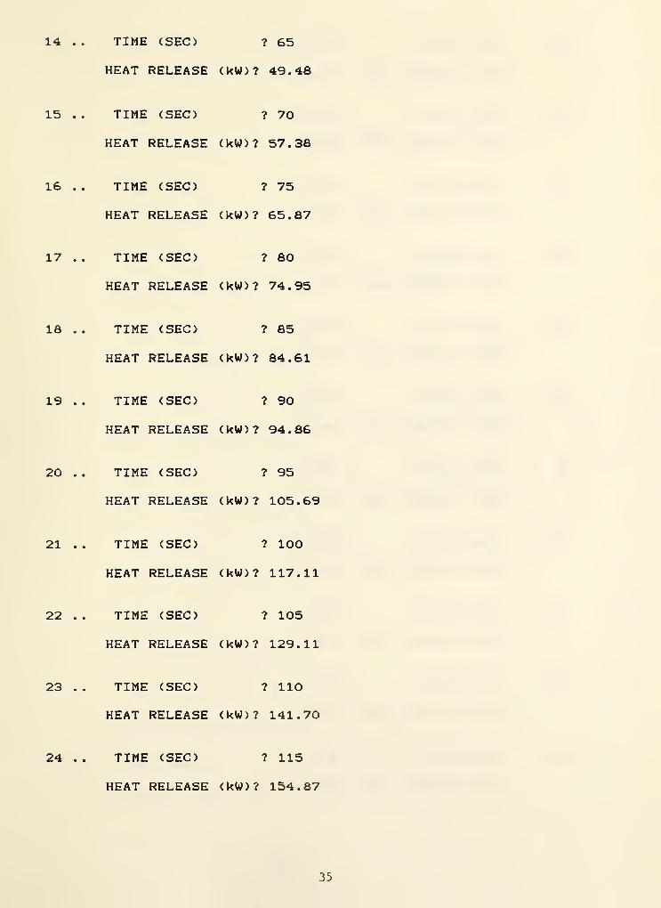
ENTER KEY HEAT RELEASE RATES THAT DETERMINE THE SHAPE OF THEDESIRED FIRE DEVELOPMENT CURVE. USUALLY THE FIRST DATAPAIR WILL BE ( TIME 0 HEAT RELEASE 0 ) . UP TO 100PAIRS CAN BE ENTERED. TO STOP ENTERING DATA ENTER ANYNEGATIVE TIME VALUE. THE PROGRAM WILL GENERATE HEATRELEASE RATE VALUES BETWEEN THE VALUES ENTERED AS NEEDEDBASED ON A STRAIGHT LINE INTERPOLATION BETWEEN POINTS ATONE SECOND INTERVALS
1 . .
2 . .
TIME (SEC) ? O
HEAT RELEASE (kW)? O
TIME (SEC) ? 5
HEAT RELEASE (kW)? 0.2928
33
3 . . TIME (SEC) ? 10
HEAT RELEASE (kW) ? 1.1711
4 . . TIME (SEC) ? 15
HEAT RELEASE (kW) ? 2.635
5 . . TIME (SEC) ? 20
HEAT RELEASE (kW) ? 4.684
6 .
.
TIME (SEC) ? 25
HEAT RELEASE (kW) ? 7.319
7 . . TIME (SEC) ? 30
HEAT RELEASE (kW) ? 10.539
8 . . TIME (SEC) ? 35
HEAT RELEASE (kW) ? 14.345
9 . . TIME (SEC) ? 40
HEAT RELEASE (kW) ? 18.737
10 . . TIME: (SEC) ? 45
HEAT RELEASE (kW) ? 23.71
11 . . TIME: (SEC) ? 50
HEAT RELEASE (kW) ? 29.28
12 . . TIME: (SEC) ? 55
HEAT RELEASE (kW) ? 35.42
13 . . TIME (SEC) ? 60
HEAT RELEASE (kW) ? 42.16
34
14 .
15 .
16 .
17 .
18 .
19 .
20 .
21 .
22 .
23 .
24 .
TIME (SEC) ? 65
HEAT RELEASE (kW)? 49.48
TIME (SEC) ? 70
HEAT RELEASE (kW)? 57.38
TIME (SEC) ? 75
HEAT RELEASE (kW)? 65.87
TIME (SEC) ? 80
HEAT RELEASE (kW)? 74.95
TIME (SEC) ? 85
HEAT RELEASE (kW)? 84.61
TIME (SEC) ? 90
HEAT RELEASE (kW)? 94.86
TIME (SEC) ? 95
HEAT RELEASE (kW)? 105.69
TIME (SEC) ? 100
HEAT RELEASE (kW)? 117.11
TIME (SEC) ? 105
HEAT RELEASE (kW)? 129.11
TIME (SEC) ? 110
HEAT RELEASE (kW)? 141.70
TIME (SEC) ? 115
HEAT RELEASE (kW)? 154.87
35
25
26
27
28
29
30
31
32
33
34
35
TIME (SEC)
HEAT RELEASE
TIME (SEC)
HEAT RELEASE
TIME (SEC)
HEAT RELEASE
TIME (SEC)
HEAT RELEASE
TIME (SEC)
HEAT RELEASE
TIME (SEC)
HEAT RELEASE
TIME (SEC)
HEAT RELEASE
TIME (SEC)
HEAT RELEASE
TIME (SEC)
HEAT RELEASE
TIME (SEC)
HEAT RELEASE
TIME (SEC)
HEAT RELEASE
? 120
(kW)? 168.63
? 125
(kW)? 182.98
? 130
(kW)? 197.91
? 135
(kW)? 213.4
? 140
(kW)? 229.5
? 145
(kW)? 246.2
? 150
(kW)? 263.5
? 155
(kW)? 281.3
? 160
(kW)? 299.8
? 165
(kW>? 318.8
? 170
(kW)? 338.4
36
36 .
37 .
36 .
39 .
40 .
41 .
42 .
43 .
44 .
45 .
46 .
TIME (SEC) ? 175
HEAT RELEASE (kW)? 358.6
TIME (SEC) ? 180
HEAT RELEASE (kW)? 379.4
TIME (SEC) ? 185
HEAT RELEASE (kW)? 400.8
TIME (SEC) ? 190
HEAT RELEASE (kW)? 422.7
TIME (SEC) ? 195
HEAT RELEASE (kW)? 445.3
TIME (SEC) ? 200
HEAT RELEASE (kW)? 468.4
TIME (SEC) ? 205
HEAT RELEASE (kW)? 492.1
TIME (SEC) ? 210
HEAT RELEASE (kW)? 516.4
TIME (SEC) ? 215
HEAT RELEASE (kW)? 541.3
TIME (SEC) ? 220
HEAT RELEASE (kW)? 556.8
TIME (SEC) ? 225
HEAT RELEASE (kW)? 592.8
37
47 .
48 .
49 .
50 .
51 .
52 .
53 .
54 .
55 .
56 .
57 .
TIME (SEC) ? 230
HEAT RELEASE <kW>? 619.5
TIME (SEC) ? 235
HEAT RELEASE <kW>? 646.7
TIME (SEC) ? 240
HEAT RELEASE (kW)? 674.5
TIME (SEC) ? 245
HEAT RELEASE (kW)? 702.9
TIME (SEC) ? 250
HEAT RELEASE (kW)? 731.9
TIME (SEC) ? 255
HEAT RELEASE (kW)? 761.5
TIME (SEC) ? 260
HEAT RELEASE (kW>? 791.6
TIME (SEC) ? 265
HEAT RELEASE (kW)? 822.4
TIME (SEC) ? 270
HEAT RELEASE (kW)? 835.7
TIME (SEC) ? 275
HEAT RELEASE (kW)? 885.6
TIME (SEC) ? 280
HEAT RELEASE (kW)? 918.1
38
58
59
60
61
62
63
64
65
66
67
68
TIME (SEC)
HEAT RELEASE
TIME (SEC)
HEAT RELEASE
TIME (SEC)
HEAT RELEASE
TIME (SEC)
HEAT RELEASE
TIME (SEC)
HEAT RELEASE
TIME (SEC)
HEAT RELEASE
TIME (SEC)
HEAT RELEASE
TIME (SEC)
HEAT RELEASE
TIME (SEC)
HEAT RELEASE
TIME (SEC)
HEAT RELEASE
TIME (SEC)
HEAT RELEASE
? 285
(kW)? 951.2
? 290
(kW)? 984.9
? 295
(kW)? 1019.1
? 300
(kW)? 1053.9
? 305
(kW)? 1089.4
? 310
(kW)? 1125.4
? 315
(kW)? 1162.0
? 320
(kW)? 1199.2
? 325
(kW)? 1236.9
? 330
(kW)? 1275.3
? 335
(kW)? 1314.2
39
TIME (SEC) ? 34069 . .
HEAT RELEASE <kW>? 1353.7
70 . . TIME (SEC) ? 345
HEAT RELEASE <kW)? 1393.8
71 .. TIME (SEC) ? 350
HEAT RELEASE (kW)? 1434.5
72 . . TIME (SEC) ? 355
HEAT RELEASE (kW)? 1475.8
73 . . TIME (SEC) ? 360
HEAT RELEASE (kW)? 1517.7
74 .. TIME (SEC) ? -1
SEND OUTPUT TO PRINTER (Y OR N) ? N
CEILING HEIGHT = 3.6576 RADIUS= 2.155 DET ACT TEMP= 54.444 RTI = 370.34
TIME FIRE GAS TEMP DET TEMPsec kW C C0.0 0.0 21 .
1
21.110.0 1.2 22.0 21 .
1
20.0 4.7 23.4 21 .
1
30.0 10.5 25.2 21.240.0 18.7 27.1 21.350.0 29.3 29.3 21.460.0 42.2 31.6 21.670.0 57.4 34.0 21.980.0 75.0 36.5 22.290.0 94.9 39.2 22.6100.0 117.1 41.9 23.1110.0 141.7 44.8 23.6120.0 168.6 47.7 24.2130.0 197.9 50.8 24.9140.0 229.5 53.8 25.7150.0 263.5 57.0 26.6160.0 299.8 60.3 27.6170.0 338.4 63 .
6
28.7180.0 379.4 67.0 29.8190.0 422.7 70.4 31 .
1
200.0 468.4 73.9 32.4
40
210.0 516.4 77.5220.0 556.8 80.6230.0 619.5 84.8240.0 674.5 88.5250.0 731.9 92.3260.0 791.6 96.2270.0 835.7 99.2280.0 918.1 104.0290.0 984.9 108.0300.0 1053.9 112.0310.0 1125.4 116.1
* * * * DETECTOR ACTUATION
33.935.437.138.840.642.644.646.748.951.253.6
AT 313.4 SECONDS ****
TYPE A CARRIAGE RETURN TO CONTINUE?
ANALYZE SAME FIRE WITH DIFFERENT DETECTOR <Y OR N) ? N
41
DETACT-QS Code Listing
102030405060708090100110120130140150160170180190200210220230240250260270280290300310320330340350360370380390400410420430440450460470480490500510520530540550
DIM 3(101)K= 10PRINTPRINTPRINTPRINTPRINTPRINTPRINTPRINTPRINTPRINTPRINTPRINTINPUTPRINTPRINTINPUTPRINTPRINTINPUTPRINTPRINTPRINTINPUTPRINTPRINTINPUTPRINTPRINTPRINTPRINTPRINTPRINTPRINT
Q ( 101
)
"DETACT-QS VERSION 1.1 WRITTEN BY"CONTRIBUTION OF THE NATIONAL BUREAU"NOT SUBJECT TO COPYRIGHT."
D.D. EVANS 1985"OF STANDARDS (U.S
"QUASI-STEADY FIRE CALCULATION OF DETECTOR ACTUATION TIME""BELOW AN UNCONFINED CEILING BASED ON ALPERT'S EQUATIONS""AS PUBLISHED IN FIRE TECHNOLOGY AUGUST 1972."
USER SUPPLIED INPUT"
HEIGHT OF CEILING ABOVE FUEL (METERS)H• • i
"DISTANCERi § oa
"INITIALT10 0 I •
"DETECTOR"(140 F =
T9OB SB
"DETECTORL
OF DETECTOR FROM AXIS OF FIRE (METERS)
ROOM TEMPERATURE (CELSIUS)
ACTUATION TEMPERATURE60 C 160 F = 71 C
(CELSIUS)"165 F = 74 C)
RESPONSE TIME INDEX ( RTI ) (m*s)~(l/2)
"NEXT A DESCRIPTION OF THE FIRE HEAT RELEASE RATE AS A""AS A FUNCTION OF TIME MUST BE CONSTRUCTED. THIS WILL BE""DONE BY THE USER ENTERING KEY HEAT RELEASE RATES ALONG""THE DESIRED FIRE CURVE. FOR THE USERS INFORMATION THE""MINIMUM HEAT RELEASE RATE NECESSARY TO ACTUATE THE""DETECTOR AT THE LOCATION GIVEN IS";
X= ( (T9-T1) *H/5.38*R~ (2/3) ) ^ (3/2)IF R/H> . 18 THEN 390X=( (T9-Tl)*H~(5/3)/16.9)~(3/2)X = X .5X= INT (X)PRINT X;PRINT " kW."PRINTPRINTPRINTPRINTPRINTPRINTPRINTPRINTPRINTPRINTPRINTPRINTN= 1
ENTER KEY HEAT RELEASE RATES THAT DETERMINE THE SHAPE OF THE"DESIRED FIRE DEVELOPMENT CURVE. USUALLY THE FIRST DATA"PAIR WILL BE ( TIME O HEAT RELEASE 0 ) . UP TO 100"PAIRS CAN BE ENTERED. TO STOP ENTERING DATA ENTER ANY"NEGATIVE TIME VALUE. THE PROGRAM WILL GENERATE HEAT"RELEASE RATE VALUES BETWEEN THE VALUESBASED ON A STRAIGHT LINE INTERPOLATIONONE SECOND INTERVALS"
ENTEREDBETWEEN
AS NEEDED"POINTS AT"
42
560 FOR 1=1 TO 101570 S ( I ) = 1 . 701412E+38580 Q ( I ) =0590 NEXT I
600 PRINT N;
610 PRINT TIME (SEC) "
;
620 INPUT S(N>630 IF S ( N ) <0 THEN 710640 PRINT " •'
650 PRINT " HEAT RELEASE ( kW ) "
;
660 INPUT Q(N)670 PRINT ° "
680 N = N-*-
1
690 PRINT " "
700 GOTO 600710 S ( N ) =S ( N- 1 ) +1720 PR = 0730 PRINT " •*
740 PRINT "SEND OUTPUT TO PRINTER <Y OR N) "
;
750 INPUT A£760 IF AS="Y" OR AS="y" THEN PR=1770 PRINT " "
780 PRINT "CEILING HEIGHT =" ; H
; " RADIUS = ";R;" DET ACT TEMP=";T9;" RTI790 PRINT " "
800 PRINT " TIME FIRE GAS TEMP DET TEMP"810 PRINT " sec kW C C"820 IF PR=0 THEN 920330 LPRINT840 LPRINT850 LPRINT860 LPRINT870 LPRINT880 LPRINT890 LPRINT900 LPRINT910 LPRINT920 I = N -
1
930 P = K940 N=0950 T4=T1960 T5=T1970 T6=T1980 J=1990 IF N<S(J+1) THEN 10201000 J= J+l1010 GOTO 9901020 0=(N-S(J))/(S(J-*-l)-S(J))*(Q(J + l)-Q(J))-a(J)1030 T4=T51040 S6=T61050 T6 = 16.9*0''(2/3)/H''(5/3)-*-Tl1060 IF R/H<=.18 THEN 10801070 T6=5.38* (0/R) ~ (2/3) /H+Tl1080 V6= . 95* (O/H) ~ (1/3)1090 IF R/H < = . 15 THEN 11101100 V6=.2*0~(l/3)*H~(l/2)/R~(5/6)
"DETACT-QS VERSION 1.1"• 8 t •
"CEILING HEIGHT=" ; H ; " m""DETECTOR DISTANCE FROM AXIS OF FIRE= " ; R
;" m"
"DETECTOR ACTUTATION TEMP=";T9;" C""RTI =
" ; L; " (m*s)~(l/2)”
ii ••
" TIME FIRE GAS TEMP DET TEMP"" sec kW C C"
43
Hi
0
112011301140115011601170118011901200121012201230124012501260127012801290130013101320133013401350136013701380139014001410142014301440145014601470148014901500151015201530154015501560157015801590160016101620163016401650
IF Vb>.i THEN 1130V6 = . 1
L1=L/V6" .5B=T6-S6T5 = T4- (S6-T4) * (1-EXP (- 1/Ll) ) -*-B*Ll*<EXP(-l/Ll ) +1/L1-1)IF P<K THEN 1200PRINT USING "########. #";N,0,S6,T4IF PR = 1 THEN LPRINT USING "######## N , 0 , S6 , T4P = 0N = N+ 1
p = p + l
IF T5<T9 THEN 990GOSUB 1680PRINT '* "
PRINT ’* **** DETECTOR ACTUATION AT";PRINT USING "######. #";E;PRINT " SECONDS ****"PRINT " "
IF PR = 0 THEN 1350LPRINT " "
LPRINT " **** DETECTOR ACTUATION AT";LPRINT USING "######.#"; E
;
LPRINT " SECONDS ***«”LPRINT " "
PRINT "TYPE A CARRIAGE RETURN TO CONTINUE";INPUT ASPRINT " "
PRINT "ANALYZE SAME FIRE WITH DIFFERENT DETECTOR <Y OR N) ";
INPUT ASIF AS="Y" OR AS= "y " THEN 1420ENDPRINT "CHANGE RTI VALUE CY OR N) ";
INPUT ASIF AS< >
" Y" AND ASO"y" THEN 1470PRINT "NEW VALUE = ";
INPUT L
PRINT "CHANGE ACTUATION TEMPERATURE <Y OR N) ";
INPUT ASIF ASO"Y" AND ASO"y" THEN 1520PRINT "NEW VALUE = ";
INPUT T9PRINT "CHANGE FUEL TO CEILING HEIGHT (Y OR N) ";
INPUT ASIF ASO"Y" AND AS< > "y " THEN 1570PRINT "NEW VALUE= ";
INPUT HPRINT "CHANGE RADIUS OF DETECTOR FROM FIRE AXIS <Y OR N) ";
INPUT ASIF ASO"Y" AND AS <
> "y " THEN 1620PRINT "NEW VALUE= ";
INPUT RPRINT "CHANGE PRINTOUT INTERVAL <Y OR N) ";
INPUT ASIF ASO"Y" AND ASO"y" THEN 1670PRINT "NEW VALUE = ";
44
1660167016601690170017101720
INPUT KGOTO 770E=N-lf (T9-T4) /(T5-T4)E = E* 100+ .
5
E=INT(E)E = E/ 100RETURN
45
NBS-114A (rev. 2-00
U.S. DEPT. OF COMM.
BIBLIOGRAPHIC DATASHEET (See instructions)
1. PUBLICATION ORREPORT NO.
NBSIR-85/3167
2. Performing Organ. Report No. 3 . Publication Date
July 1985
4. TITLE AND SUBTITLE
Methods to Calculate the Response Time of Heat and Smoke Detectors
Installed Below Large Unobstructed Ceilings
5. AUTHOR(S)
David D. Evans, David W. Stroup
6. PERFORMING ORGANIZATION (If joint or other than NBS, see instructions) 7 . Contract/Grant No.
NATIONAL BUREAU OF STANDARDSDEPARTMENT OF COMMERCE 8. Type of Report & Period Covered
WASHINGTON, D.C. 20234
9. SPONSORING ORGANIZATION NAME AND COMPLETE ADDRESS (Street. City. State. ZIP)
U.S. Nuclear Regulatory CommissionWashington, D.C. 20555 ,
10.
SUPPLEMENTARY NOTES
| |
Document describes a computer program; SF-185, FIPS Software Summary, is attached.
11.
ABSTRACT (A 200-word or less factual summary of most significant information. If document includes a si gnifi cantbi bl iography or literature survey, mention it here)
Recently developed methods to calculate the time required for ceiling mounted
heat and smoke detectors to respond to growing fires are reviewed. A computer pro-
gram, that calculates activation times for both fixed temperatures and rate of
rise heat detectors in response to fires that increase in heat release rate
proportionally with the square of time from ignition is given. This program produces
equivalent results to the tables published in Appendix C, Guide for Automatic
Fire Detector Spacing, (NEPA 72E, 1984). A separate method and corresponding pro-
gram are provided to calculate response time for fires having arbitrary heat release
rate histories. This method is based on quasi—steady ceiling layer gas flow
assumptions. Assuming a constant proportionality between smoke and heat release
from burning materials, a method is described to calculate smoke detector response
time modeling the smoke detector as a low temperature heat detector in either of the
two response time models.
12.
KEY WORDS (Six to twelve entries; alphabetical order; capitalize only proper names; and separate key words by semicolons)
ceilings; computer program; egress; escape; fire alarms; fire detection; fire
suppression; heat detectors; smoke detectors; sprinkler systems
13. AVAILABILITY
^ |
Uni i mi ted
| |
For Official Distribution. Do Not Release to NTIS
Order From Superintendent of Documents, U.S. Government Printing Office, Washington, D.C.20402.
Order From National Technical Information Service (NTIS), Springfield, VA. 22161
14. NO. OFPRINTED PAGES
49
15. Price
$8.50USCOMM-DC 6043-P80