38
Lesson 6 Electricity, Components, Circu ARRL: Chapter 3.1 and 3.2 G. West Electrons, Go with the flow
| Date post: | 22-Dec-2015 |
| Category: |
Documents |
| Upload: | stanley-nichols |
| View: | 232 times |
| Download: | 0 times |

Lesson 6Electricity, Components, Circuits
ARRL: Chapter 3.1 and 3.2 G. WestElectrons, Go with the flow

Metric Units
Convert downDecimal Right
Convert upDecimal Left
Example 1: 5MHz = ? kHz5000 kHz
Example 2: 50 mA = ? A .05 A
Unit
Example 2: 1.00 dollar = ? dimes10 dimes
Example 3: 1.00 dollar = ? pennies100 cents
T5BO2T5B03T5B04T5B05T5B06T5B07T5B08
GRACE SAYS “ LEFT UP RIGHT DOWN”

T5B02What is another way to specify a radio signal frequency of 1,500,000 hertz?A. 1500 kHzB. 1500 MHzC. 15 GHzD. 150 kHz
1,500,000. hertz?
1.500,000 M hertz?1.5 MHz
1,500.000 k hertz?1500 kHz
.001,500,000 G hertz?
.0015 GHz
(A)

T5B06If an ammeter calibrated in amperes is used to measure a 3000-milliampere current, what reading would it show?A. 0.003 amperesB. 0.3 amperesC. 3 amperesD. 3,000,000 amperes
milli = 1/1000 or .oo1 or divide by 1000
3000 / 1000 = 3
Or simply we are moving up the scale 3 powers of 10From milli to unit. Move the decimal 3 places to the left
3 0 0 0. milliamp = 3 amps
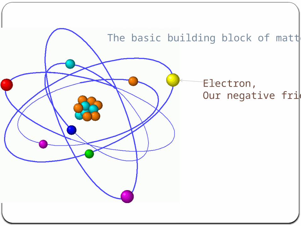
The atomThe basic building block of matter
Electron,Our negative friend

ConductorsLoosely bonded electrons
Example: copper T5A07
InsulatorsTightly bonded electrons
Example: Glass, wood, plasticT5A08
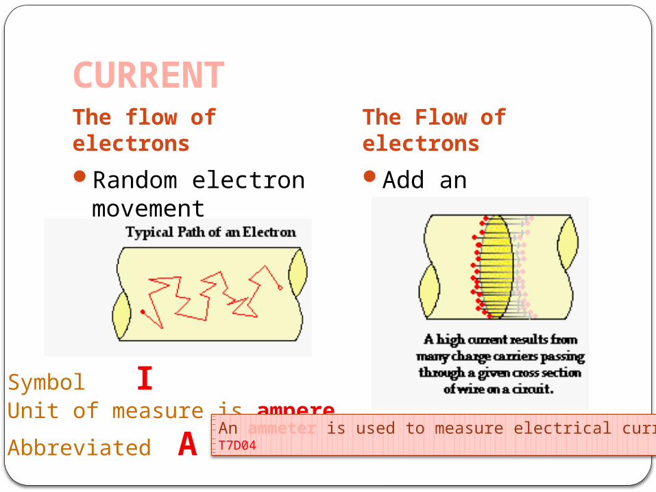
CURRENTThe flow of electrons
The Flow of electrons
Random electron movement
Add an electrical potential
Symbol I Unit of measure is ampere
Abbreviated AAn ammeter is used to measure electrical currentT7D04

VOLTAGEVoltage is the force that moves electrons
T5A05
Symbol E Electro Motive Force
The magnitude is measured in Volts
Abbreviated V Voltage is measured with a voltmeter

Electrons flowing through a conductorCreate a magnetic field.
Electric current is the flow of electrons.T5A03
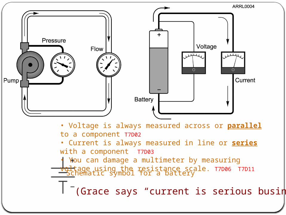
Schematic symbol for a battery
• Voltage is always measured across or parallel to a component T7D02
• Current is always measured in line or series with a component T7D03
• You can damage a multimeter by measuring voltage using the resistance scale. T7D06 T7D11
(Grace says “current is serious business”)

Nickel-metal hydride Lithium-ion Lead-acid gel-cellNickel-cadmium
Carbon-zinc
T6A10 T6A11 Batteries
Portable BatteriesPortable batteries
T6A10 Chargeable
T6A11 Not Chargeable

Series circuit
Parallel circuit

Multimeter
13
T7D06 Attempting to measure voltage when using the resistance setting might damage a multimeter.
T7D07 Voltage and resistance are measurements commonly made using a multimeter.
Volt Ohm Meter VOMDigital Volt Ohm Meter Much more accurate
T7D11 Ensure the circuit is not poweredwhen measuring resistance

Resistors
Symbol R for resistanceUnit of measure is the Ohm
Abbreviated Ω
Schematic symbol Resistors are poor conductors andResist the flow of Current
Resistance is measured with an ohmmeterT7D05

Ohm’s Law• E is voltage
– Units - volts• I is current
– Units - amperes• R is resistance
– Units - ohms
• R = E/I• I = E/R T5D01 02 03
• E = I x R
Examples: T5D04 - T5D12

T5D05What is the resistance in a circuit for which the applied voltage is 12 volts and the current flow is 1.5 amperes?A. 18 ohmsB. 0.125 ohmsC. 8 ohmsD. 13.5 ohms
T5D09What is the current flowing through a 24-ohm resistor connected across 240 volts?A. 24,000 amperesB. 0.1 amperesC. 10 amperesD. 216 amperes
(C)
(C)

Two Basic Kinds of Current
• When current flows in only one direction, it is called direct current (dc). T5A04
– Batteries are a common source of dc.– Most electronic devices are powered
by dc.• When current flows alternatively in
one direction then in the opposite direction, it is called alternating current (ac). T5A09
– Your household current is ac.

AC / DC
Electrons can either flow in one directionor alternate and flow in the opposite direction by changing the polarity of the voltage.
+
-0

Moving Electrons Doing Something Useful
• Any time energy is expended to do something, work is performed.
• When moving electrons do some work, power is consumed.
• Power is measured in the units of watts (W). T5A02

Power Formula
• Power is defined as the amount of current that is being pushed through a conductor or device to do work.– P = I x E T5C08
– E = P/I– I = P/E
P
I E

T5C09 How much power is being used in a circuit when the applied voltage is 13.8Volts DC and the current is 10 amps
P=IE
P= 13.8 X 10
P= 138 Watts

Other basic circuit componentsCapacitors Stores energy in an electric field Unit of measure – Farad, F
Inductors Stores energy in a magnetic fieldUnit of measure – Henry, H
Diodes One way valve
Transistors Electronic switch or amplifier
Integrated circuits Electronic component integrating many components in one package
Semiconductors

Capacitors
Store energy in an electric field T6A04
Capacitors oppose the change in voltage

24
T6A04 A capacitor is the electrical component that stores energy in an electric field.
24
Typical construction and schematic symbol for capacitors.
Various fixed capacitors

Inductors• Store energy in a magnetic field T5C03 T6A06
Symbol LUnit of measure is HenryAbbreviated H
Schematic symbol for an inductor
Inductors oppose the change of current

Resonant circuits
Circuits containing both capacitors and inductorsWill have at least one resonant frequency.T6D08
Components that oppose AC voltage or current have reactance • Capacitive reactance or • Inductive reactance
•The combination of resistance and reactance is called impedance. symbol Z

Diodes, Transistors, and Integrated CircuitsSemi Conductors
•Diode - A semiconductor that allows current to flow only in one direction. T6B02
•A heavy duty diode is called a rectifier•Rectifiers are used to change AC into pulsating DC •A diode has two electrodes, anode and cathode •A special diode that gives off light is a LED (light emitting diode) T6B07 T6D07
• Primarily the active element is silicone.• Impurities are added to create special properties

Transistors
28
T6B03 A transistor is a component that can be used as an electronic switch or amplifier.
T6B04 The bipolar junction transistor is a component that is made of three layers of semiconductor material.
Small Signal Transistors
Schematic Symbol

29
Gate Keepers
T6A08 A switch is an electrical component that is used to connect or disconnect electrical circuits.
T6A09 A fuse is an electrical component used to protect other circuit components from current overloads.
29
Toggle Switch
Slide Switch
Rocker Switch
Slow Blow Fuse Automobile
Fuse
Schematic Symbol
Schematic Symbol

30
Display Components
T6D04 A meter can be used to display signal strength on a numeric scale.
30Icom 7700
S-Meter

31
Schematic Symbols
T6C01 Schematic symbols is the name for standardized representations of components in an electrical wiring diagram.
31

SCHEMATIC SYMBOLS
32
T6C12 The symbols on an electrical circuit schematic diagram represent electrical components.

33
T6C: Circuit diagrams; schematic symbols
T6C04 Component 1 in figure T1 is a
33
12
3
4
5
12
3
4
5Figure T1
Resistor
Component 2 in figure T1 is a
Transistor
Lamp
Component 3 in figure T1 is a

34
T6C: Circuit diagrams; schematic symbols
Component 6 in figure T2 is a
34
1
2 5
4
3
6
7
8
9
10
1
2 5
4
3
6
7
8
9
10
Figure T2
CapacitorLED
Variable resistor
Transformer
Component 9 in figure T2 is a
Component 8 in figure T2 is a
Component 4 in figure T2 is a
Component 3 in figure T2 is a
STSP switch

35
T6C: Circuit diagrams; schematic symbols
T6C11 Component 4 in figure T3 is an
35
1
2
3
4
1
2
3
4
Figure T3
Component 3 in figure T3 is aAntenna
Variable inductor

By controlling the movements of electronsthrough our circuits. We can have circuits do specific tasks.
Components throughout circuits are a lotlike the bumpers in a pin ball machine

For Next WeekStudy flash cards www.hamexam.org
73Tom and Jack
Lesson 1• T1B• T3B• T8A
Lesson 2• T1A• T1C• TID• T1E• T1F
Lesson 4• T3A• T3C• T9A• T9B• T7C
Lesson 5• T4A• T4B• T7A• T7B• T8D
Lesson 6• T5A• T5B• T5C• T5D• T6A• T6B• T6C• T6D• T7D
Lesson 3• T2A• T2B• T2C• T8B• T8C
Lesson 7• T0A• T0B• T0C
Radio Fundamentals
Rules &Regs.
Comm. w/Others
AntennasPropagation
Equipment Electricity Safety

To Bring
AmmeterMultimeterElectro magneticConductorInsulatorsResistorCapacitorInductorCircuitClear tube and marbleShock absorberTuning forkBall magnet and al tube.


