91
37353A Manual Version 3.1xxx Manual 37353A MFR 13 Packages Protection Relay

37353A
Manual Version 3.1xxx
Manual 37353A
MFR 13 Packages Protection Relay
Manual 37353A MFR 13 Packages - Protection Relay
Page 2/91 © Woodward
WARNING Read this entire manual and all other publications pertaining to the work to be performed before install-ing, operating, or servicing this equipment. Practice all plant and safety instructions and precautions. Failure to follow instructions can cause personal injury and/or property damage. The engine, turbine, or other type of prime mover should be equipped with an overspeed (overtempera-ture, or overpressure, where applicable) shutdown device(s), that operates totally independently of the prime mover control device(s) to protect against runaway or damage to the engine, turbine, or other type of prime mover with possible personal injury or loss of life should the mechanical-hydraulic gov-ernor(s) or electric control(s), the actuator(s), fuel control(s), the driving mechanism(s), the linkage(s), or the controlled device(s) fail. Any unauthorized modifications to or use of this equipment outside its specified mechanical, electrical, or other operating limits may cause personal injury and/or property damage, including damage to the equipment. Any such unauthorized modifications: (i) constitute "misuse" and/or "negligence" within the meaning of the product warranty thereby excluding warranty coverage for any resulting damage, and (ii) invalidate product certifications or listings.
CAUTION To prevent damage to a control system that uses an alternator or battery-charging device, make sure the charging device is turned off before disconnecting the battery from the system. Electronic controls contain static-sensitive parts. Observe the following precautions to prevent dam-age to these parts. • Discharge body static before handling the control (with power to the control turned off, contact a
grounded surface and maintain contact while handling the control). • Avoid all plastic, vinyl, and Styrofoam (except antistatic versions) around printed circuit boards. • Do not touch the components or conductors on a printed circuit board with your hands or with
conductive devices.
OUT-OF-DATE PUBLICATION This publication may have been revised or updated since this copy was produced. To verify that you have the latest revision, be sure to check the Woodward website: http://www.woodward.com/pubs/current.pdf The revision level is shown at the bottom of the front cover after the publication number. The latest version of most publications is available at: http://www.woodward.com/publications If your publication is not there, please contact your customer service representative to get the latest copy.
Important definitions
WARNING Indicates a potentially hazardous situation that, if not avoided, could result in death or serious injury.
CAUTION Indicates a potentially hazardous situation that, if not avoided, could result in damage to equipment.
NOTE Provides other helpful information that does not fall under the warning or caution categories.
Woodward reserves the right to update any portion of this publication at any time. Information provided by Woodward is believed to be correct and reliable. However, Woodward assumes no responsibility unless otherwise expressly undertaken.
© Woodward
All Rights Reserved.

Manual 37353A MFR 13 Packages - Protection Relay
© Woodward Page 3/91
Revision History
Rev. Date Editor Changes NEW 06-03-02 TP Release based on 37142B A 07-07-18 TP Zero voltage monitoring parameters corrected; description of inverse time overcurrent monitoring improved
Contents
CHAPTER 1. GENERAL INFORMATION.........................................................................................7 Introduction .............................................................................................................................................7 Measurement Value Logging ..................................................................................................................8 Package Functional Descriptions ...........................................................................................................9 CHAPTER 2. ELECTROSTATIC DISCHARGE AWARENESS...........................................................10 CHAPTER 3. INSTALLATION .....................................................................................................11 Wiring Diagram .....................................................................................................................................11 Power Supply (Packages GP / GPX / GPX-I / GPY-I / K08).................................................................12 Wide Range Power Supply (Package GPY-I-N)...................................................................................12 Measuring Inputs...................................................................................................................................13
Voltage........................................................................................................................................13 Current ........................................................................................................................................14
Discrete Inputs ......................................................................................................................................15 Outputs..................................................................................................................................................16
Relay Outputs (Standard / Packages GPX / GPX-I / GPY-I / GPY-I-N / K08) ...........................16 Pulse Output (Packages GPY-I / GPY-I-N) ................................................................................16 Analog Outputs (Packages GPY-I / GPY-I-N) ............................................................................17
Interface (Packages GPX-I / GPY-I / GPY-I-N / K08) ...........................................................................18 Modbus Interface ........................................................................................................................18 DPC - Direct Configuration Interface ..........................................................................................19
CHAPTER 4. FUNCTIONAL DESCRIPTION ..................................................................................20 Control Inputs........................................................................................................................................20 Control Outputs .....................................................................................................................................21 Direction of Power.................................................................................................................................22 Power Factor Definition.........................................................................................................................23 Alarms ...................................................................................................................................................25
Alarm Messages .........................................................................................................................25 Alarm Acknowledgement ............................................................................................................25
CHAPTER 5. DISPLAY AND OPERATING ELEMENTS...................................................................26 Brief Description of LEDs and Push Buttons ........................................................................................26 LEDs......................................................................................................................................................27 Push Buttons.........................................................................................................................................28 LC Display.............................................................................................................................................29
Display in Automatic Mode (First Line of the Display: Measured Values)..................................29 Display in Automatic Mode (Second Line of the Display: Measured Values) ............................29 Display in Automatic Mode (Second Line of the Display: Alarm Indication)...............................30
Manual 37353A MFR 13 Packages - Protection Relay
Page 4/91 © Woodward
CHAPTER 6. CONFIGURATION ................................................................................................. 31 Basic Data ............................................................................................................................................ 32 Configuration Access............................................................................................................................ 32
Password.................................................................................................................................... 32 Change Passwords .................................................................................................................... 33
Direct Configuration.............................................................................................................................. 34 Measurement........................................................................................................................................ 35
Voltage Measurement ................................................................................................................ 35 Potential Transformer Configuration .......................................................................................... 35 Current Measurement ................................................................................................................ 36 Rated Values (Packages GPX / GPX-I / GPY-I / GPY-I-N / K08) .............................................. 37 Power Measurement .................................................................................................................. 37
Control Functions ................................................................................................................................. 38 Synchronization (Packages GPX / GPX-I / GPY-I / GPY-I-N / K08).......................................... 38
Type of Monitoring................................................................................................................................ 40 Protection.............................................................................................................................................. 41
Overvoltage Monitoring .............................................................................................................. 41 Undervoltage Monitoring ............................................................................................................ 42 Zero Voltage Monitoring ............................................................................................................. 43 Voltage Asymmetry Monitoring .................................................................................................. 44 Overfrequency Monitoring.......................................................................................................... 45 Underfrequency Monitoring........................................................................................................ 46 Independent Time-Overcurrent Monitoring ................................................................................ 47 Inverse Time-Overcurrent Monitoring ........................................................................................ 49 Inverse Time-Overcurrent Monitoring with Voltage Restraint .................................................... 52 Ground Fault Monitoring, Calculated (Packages GP / K08) ...................................................... 54 Overload Monitoring ................................................................................................................... 55 Reverse/Reduced Power Monitoring ......................................................................................... 56 Unbalanced Load Monitoring ..................................................................................................... 57 Reactive Power Monitoring ........................................................................................................ 58
Relay Configuration .............................................................................................................................. 59 Auto Acknowledgement of the Relays ....................................................................................... 59 Auto Acknowledgement of Messages........................................................................................ 60 Changing the Relay Assignment................................................................................................ 61
Pulse Output of the Positive Active Energy (Packages GPY-I / GPY-I-N)........................................... 63 Analog Outputs (Packages GPY-I / GPY-I-N) ...................................................................................... 64 Interface (Packages GPX-I / GPY-I / GPY-I-N / K08)........................................................................... 66
Screens for Modbus RTU Slave Protocol .................................................................................. 66 General Interface Screens ......................................................................................................... 67
CHAPTER 7. COMMISSIONING.................................................................................................. 68 APPENDIX A. DIMENSIONS ...................................................................................................... 70 APPENDIX B. TECHNICAL DATA .............................................................................................. 71 APPENDIX C. MEASURED QUANTITIES AND ACCURACY............................................................ 73 APPENDIX D. INTERFACE TELEGRAM....................................................................................... 74 Communication Interface Addresses ................................................................................................... 74
Transmission Message .............................................................................................................. 74 Receive Message....................................................................................................................... 77
Description of the Data Format............................................................................................................. 78 Examples.................................................................................................................................... 79 Bit Change at Tripping of a Watchdog Function ........................................................................ 79
Framework Data for the Interfaces....................................................................................................... 79 Framework Data for Modbus RTU Slave ................................................................................... 79
APPENDIX E. LIST OF PARAMETERS........................................................................................ 80
Manual 37353A MFR 13 Packages - Protection Relay
© Woodward Page 5/91
APPENDIX F. SERVICE OPTIONS ..............................................................................................86 Product Service Options .......................................................................................................................86 Returning Equipment for Repair ...........................................................................................................86
Packing a Control .......................................................................................................................87 Return Authorization Number RAN ............................................................................................87
Replacement Parts................................................................................................................................87 How to Contact Woodward ...................................................................................................................88 Engineering Services ............................................................................................................................89 Technical Assistance ............................................................................................................................90
Manual 37353A MFR 13 Packages - Protection Relay
Page 6/91 © Woodward
Illustrations and Tables
Illustrations Figure 3-1: Wiring diagram ..................................................................................................................................................... 11 Figure 3-2: Power supply......................................................................................................................................................... 12 Figure 3-3: Wide range power supply...................................................................................................................................... 12 Figure 3-4: Measuring inputs - voltages .................................................................................................................................. 13 Figure 3-5: Measuring inputs - synchronizing voltage ............................................................................................................ 13 Figure 3-6: Measuring inputs - current .................................................................................................................................... 14 Figure 3-7: Discrete inputs....................................................................................................................................................... 15 Figure 3-8: Relay outputs ........................................................................................................................................................ 16 Figure 3-9: Pulse output........................................................................................................................................................... 16 Figure 3-10: Analog outputs .................................................................................................................................................... 17 Figure 3-11: Interfaces............................................................................................................................................................. 18 Figure 4-1: Direction of power ................................................................................................................................................ 22 Figure 5-1: Front panel ............................................................................................................................................................ 26 Figure 6-1: Diagram for independent time-overcurrent monitoring ........................................................................................ 47 Figure 6-2: Inverse time-overcurrent - characteristic "normal inverse"................................................................................... 50 Figure 6-3: Inverse time-overcurrent - characteristic "very inverse" ....................................................................................... 51 Figure 6-4: Inverse time-overcurrent - characteristic "extremely inverse" .............................................................................. 51 Figure 6-5: Characteristic of the inverse time-overcurrent monitoring with voltage restraint (knee curve setting 20 %) ....... 52 Figure 7-1: Dimensions............................................................................................................................................................ 70 Figure 7-2: Interface, power factor scaling .............................................................................................................................. 78 Figure 7–3: Interface - Modbus connection ............................................................................................................................. 79
Tables Table 3-1: Conversion chart - wire size ................................................................................................................................... 12 Table 4-1: Alarm messages...................................................................................................................................................... 25 Table 5-1: Alarm messages...................................................................................................................................................... 30 Table 6-1: Release delay of the relays ..................................................................................................................................... 60 Table 6-2: Protective function output to relay ......................................................................................................................... 62 Table 6-3: Analog outputs, table of values .............................................................................................................................. 64 Table 7-1: Analog outputs, table of values .............................................................................................................................. 85

Manual 37353A MFR 13 Packages - Protection Relay
© Woodward Page 7/91
Chapter 1. General Information
Introduction ≡≡≡≡≡≡≡≡≡≡≡≡≡≡≡≡≡≡≡≡≡≡≡≡≡
The MFR 13 is an intelligent protection unit. The primary values are measured over integrated voltage and cur-rent measuring inputs and converted into configurable limit values which are displayed and monitored. These values can be monitored for exceeding/falling below the configured value. The detailed model description for the MFR 13 reads as follows: MFR1315 B/ ABDEF..Z
Packages according to the package list.
These packages can be found in the manual. Each chapter headline points out if the described function is standard or part of a package.
Mounting [B].. Flush-mounting
Current transformer, secondary
[1] = ../1 A [5] = ../5 A
Voltage transformer/PTs, secondary
[1] = 100 Vac [4] = 400 Vac
Type Examples: • MFR1341B/GPX (flush mounted, standard unit with 400 Vac PT and ../1 A CT inputs with 8 configurable re-
lays, true RMS busbar voltage measuring, and synch-check function) • MFR1315B/ GPY-I-N (flush mounted, standard unit with 100 Vac PT and ../5 A CT inputs with
8 configurable relays, 3 analog outputs, pulse output, true RMS busbar voltage measuring synch-check func-tion, RS-485 Modbus RTU Slave interface, and wide-range power supply)

Manual 37353A MFR 13 Packages - Protection Relay
Page 8/91 © Woodward
Measurement Value Logging ≡≡≡≡≡≡≡≡≡≡≡≡≡≡≡≡≡≡≡≡≡≡≡≡≡
Voltage Voltage is displayed as three-phase r.m.s measurement of the phase-neutral and/or phase-phase voltages. Packages GPX / GPX-I / GPY-I / GPY-I-N utilize single-phase r.m.s. measurement of the synchronizing volt-age VL1-L2. This device can be ordered with the following measuring voltage input ranges (rated voltages). Please indi-cate the measuring voltage input required when ordering (refer to Technical Data on page 71): • 66 V/115 V.................... [1] • 230 V/400 V.................... [4]
Frequency
Frequency measurement is extracted from the digitally filtered measuring voltages. The frequency is meas-ured three-phase if the measured voltage exceeds 15% of the nominal voltage. This ensures rapid and precise measurement of the frequency. However the frequency is still measured correctly even if voltage is only ap-plied to one phase.
Current
Three-phase measurement of the r.m.s. value. - ../1 A ...................................... [1] - ../5 A ...................................... [5]
Ground fault
The ground fault current is a calculation of the vectorial sum of the three phase currents (Package GP). This measurement is suitable for line-to-ground monitoring in a solidly or resistance grounded mains (e.g. In phase-to-phase low voltage mains). The line-to-ground current should at least represent 10% of the current transformer rated current in order to ensure reliable operation.
Active power
The active load is measured though real time multiplication of either the three phase-to-neutral voltages and the three-phase conductor currents or single-phase measurement of voltage V12 and the current I1.
Reactive power
The reactive power is calculated from the measured single-phase voltage V12 and the single-phase current I1. Power factor
Power factor is calculated time difference between the digitally filtered voltage V12 and current I1. The power factor is accurately measured for both clockwise and counter-clockwise phase sequences.
Active energy
Active energy combines a time measurement with the measured positive active load. The counter is incorpo-rated in the non-volatile memory and only computes positive energy. The memory is updated every 3 minutes with a resolution of 0.1 kWh. The unit automatically increases the engineering unit of measure when the maximum value has been reached. This permits a measuring range up to 4,290 GWh. This counter is not Physikalisch-Technische Bundesanstalt (PTB) calibrated.
Manual 37353A MFR 13 Packages - Protection Relay
© Woodward Page 9/91
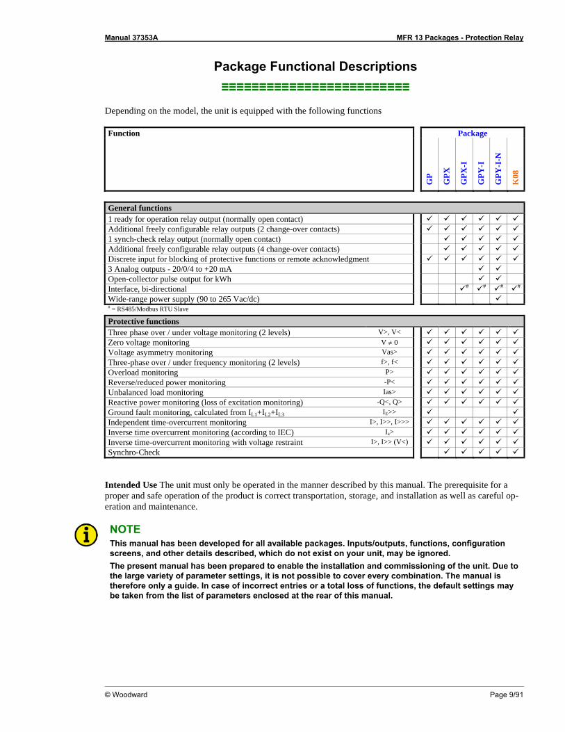
Package Functional Descriptions ≡≡≡≡≡≡≡≡≡≡≡≡≡≡≡≡≡≡≡≡≡≡≡≡≡
Depending on the model, the unit is equipped with the following functions Function Package
GP
GPX
GPX
-I
GPY
-I
GPY
-I-N
K08
General functions 1 ready for operation relay output (normally open contact) Additional freely configurable relay outputs (2 change-over contacts) 1 synch-check relay output (normally open contact) Additional freely configurable relay outputs (4 change-over contacts) Discrete input for blocking of protective functions or remote acknowledgment 3 Analog outputs - 20/0/4 to +20 mA Open-collector pulse output for kWh Interface, bi-directional # # # #
Wide-range power supply (90 to 265 Vac/dc) # = RS485/Modbus RTU Slave Protective functions Three phase over / under voltage monitoring (2 levels) V>, V< Zero voltage monitoring V ≠ 0 Voltage asymmetry monitoring Vas> Three-phase over / under frequency monitoring (2 levels) f>, f< Overload monitoring P> Reverse/reduced power monitoring -P< Unbalanced load monitoring Ias> Reactive power monitoring (loss of excitation monitoring) -Q<, Q> Ground fault monitoring, calculated from IL1+IL2+IL3 IE>> Independent time-overcurrent monitoring I>, I>>, I>>> Inverse time overcurrent monitoring (according to IEC) Ia> Inverse time-overcurrent monitoring with voltage restraint I>, I>> (V<) Synchro-Check
Intended Use The unit must only be operated in the manner described by this manual. The prerequisite for a proper and safe operation of the product is correct transportation, storage, and installation as well as careful op-eration and maintenance.
NOTE This manual has been developed for all available packages. Inputs/outputs, functions, configuration screens, and other details described, which do not exist on your unit, may be ignored. The present manual has been prepared to enable the installation and commissioning of the unit. Due to the large variety of parameter settings, it is not possible to cover every combination. The manual is therefore only a guide. In case of incorrect entries or a total loss of functions, the default settings may be taken from the list of parameters enclosed at the rear of this manual.

Manual 37353A MFR 13 Packages - Protection Relay
Page 10/91 © Woodward
Chapter 2. Electrostatic Discharge Awareness
All electronic equipment is static-sensitive, some components more than others. To protect these components from static damage, you must take special precautions to minimize or eliminate electrostatic discharges. Follow these precautions when working with or near the control. 1. Before doing maintenance on the electronic control, discharge the static electricity on your body to
ground by touching and holding a grounded metal object (pipes, cabinets, equipment, etc.). 2. Avoid the build-up of static electricity on your body by not wearing clothing made of synthetic materials.
Wear cotton or cotton-blend materials as much as possible because these do not store static electric char-ges as easily as synthetics.
3. Keep plastic, vinyl, and Styrofoam materials (such as plastic or Styrofoam cups, cigarette packages, cello-
phane wrappers, vinyl books or folders, plastic bottles, etc.) away from the control, modules, and work area as much as possible.
4. Opening the control cover may void the unit warranty.
Do not remove the printed circuit board (PCB) from the control cabinet unless absolutely necessary. If you must remove the PCB from the control cabinet, follow these precautions:
• Ensure that the device is completely voltage-free (all connectors have to be disconnected).
• Do not touch any part of the PCB except the edges.
• Do not touch the electrical conductors, connectors, or components with conductive devices or with
bare hands.
• When replacing a PCB, keep the new PCB in the plastic antistatic protective bag it comes in until you are ready to install it. Immediately after removing the old PCB from the control cabinet, place it in the antistatic protective bag.
CAUTION To prevent damage to electronic components caused by improper handling, read and observe the pre-cautions in Woodward manual 82715, Guide for Handling and Protection of Electronic Controls, Printed Circuit Boards, and Modules.
Manual 37353A MFR 13 Packages - Protection Relay
© Woodward Page 11/91
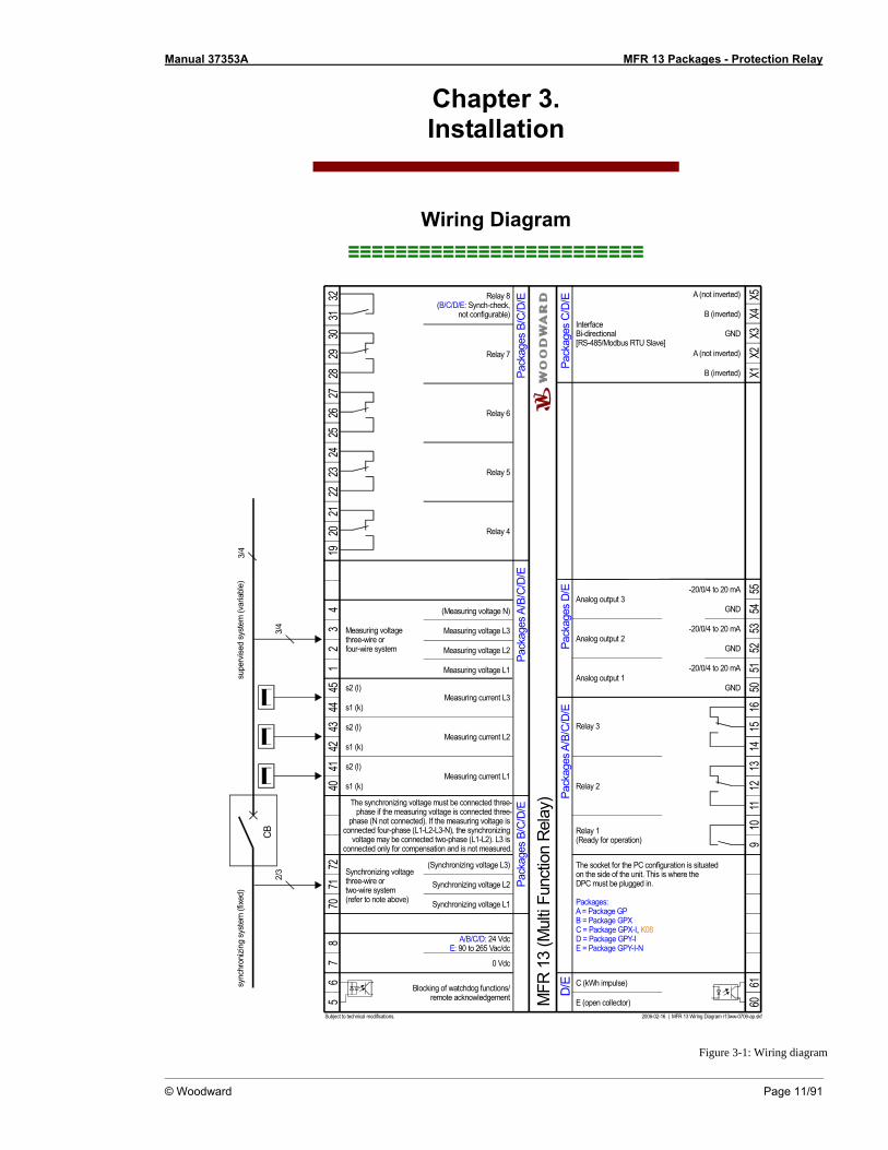
Chapter 3. Installation
Wiring Diagram ≡≡≡≡≡≡≡≡≡≡≡≡≡≡≡≡≡≡≡≡≡≡≡≡≡
supe
rvise
d sy
stem
(var
iabl
e)
s2 (l)
s1 (k)
s2 (l)
s1 (k)
s1 (k)
s2 (l)
Subject to technical modifications.
78
CB
4041
4342
4445
Measuring current L1
Measuring current L2
Measuring current L3
3/4
E (open collector)
C (kWh impulse)
Relay 2
Relay 1(Ready for operation)
2006-02-16 | MFR 13 Wiring Diagram r13ww-0706-ap.skf
6061
1211
109
1316
1514
Pack
ages
B/C
/D/E
A/B/C/D: 24 VdcE: 90 to 265 Vac/dc
2721
2019
2226
2524
2328
3231
3029
Relay 4
Relay 5
Relay 6
Relay 7
Pack
ages
B/C
/D/E
Measuring voltage L1
715
670
721
Synchronizing voltage L2
Blocking of watchdog functions/remote acknowledgement
Synchronizing voltage L1
(Synchronizing voltage L3)
Measuring voltagethree-wire orfour-wire system2
43
(Measuring voltage N)
Measuring voltage L2
Measuring voltage L3
Relay 8(B/C/D/E: Synch-check,
not configurable)
Relay 3
The socket for the PC configuration is situatedon the side of the unit. This is where the DPC must be plugged in.
Packages:A = Package GPB = Package GPXC = Package GPX-I, K08D = Package GPY-IE = Package GPY-I-N
MFR
13
(Mul
ti Fu
nctio
n Re
lay)
0 Vdc
Pack
ages
A/B
/C/D
/E
InterfaceBi-directional[RS-485/Modbus RTU Slave]
X4
A (not inverted)
GND
B (inverted)
X3X2
X1X5
Pack
ages
C/D
/EPa
ckag
es D
/ED/
E
Analog output 1
3/4
2/3
GND 5051
Analog output 2GND 52
53
Analog output 3GND 54
55
Pack
ages
A/B
/C/D
/E
-20/0/4 to 20 mA
-20/0/4 to 20 mA
-20/0/4 to 20 mA
sync
hron
izin
g sy
stem
(fixe
d)
The synchronizing voltage must be connected three-phase if the measuring voltage is connected three-
phase (N not connected). If the measuring voltage is connected four-phase (L1-L2-L3-N), the synchronizing
voltage may be connected two-phase (L1-L2). L3 is connected only for compensation and is not measured.
Synchronizing voltagethree-wire ortwo-wire system(refer to note above)
A (not inverted)
B (inverted)
Figure 3-1: Wiring diagram

Manual 37353A MFR 13 Packages - Protection Relay
Page 12/91 © Woodward
WARNING All technical data and ratings indicated in this chapter are not definite! Only the values indicated under Technical Data on page 71 are valid!
CAUTION A circuit breaker must be located near to the unit and in a position easily accessible to the operator. This must also bear a sign identifying it as an isolating switch for the unit.
NOTE Inductive devices connected to the system (such as operating current coils, undervoltage tripping units, or auxiliary/power contacts) must be connected to a suitable interference suppressor.
The following chart may be used to convert square millimeters [mm²] to AWG and vice versa:
AWG mm² AWG mm² AWG mm² AWG mm² AWG mm² AWG mm² 30 0.05 21 0.38 14 2.5 4 25 3/0 95 600MCM 300 28 0.08 20 0.5 12 4 2 35 4/0 120 750MCM 400 26 0.14 18 0.75 10 6 1 50 300MCM 150 1000MCM 500 24 0.25 17 1.0 8 10 1/0 55 350MCM 185 22 0.34 16 1.5 6 16 2/0 70 500MCM 240
Table 3-1: Conversion chart - wire size
Power Supply (Packages GP / GPX / GPX-I / GPY-I / K08) ≡≡≡≡≡≡≡≡≡≡≡≡≡≡≡≡≡≡≡≡≡≡≡≡≡
18 to 30 Vdc
78
0 V18 to 30 Vdc
Standard
Power supply
Figure 3-2: Power supply
Terminal Description Amax Standard power supply unit (Packages GP / GPX / GPX-I / GPY-I / K08)
8 18 to 30 Vdc 2.5 mm² 7 0 V reference point 2.5 mm²
Wide Range Power Supply (Package GPY-I-N) ≡≡≡≡≡≡≡≡≡≡≡≡≡≡≡≡≡≡≡≡≡≡≡≡≡
78
Wide-range power supply
- / N+ / L
Power supply
90 to 265 Vac/dc
Figure 3-3: Wide range power supply
Terminal Description Amax Wide range power supply unit (Package GPY-I-N)
8 90 to 265 Vac/dc 2.5 mm² 7 0 V reference point 2.5 mm²

Manual 37353A MFR 13 Packages - Protection Relay
© Woodward Page 13/91
Measuring Inputs ≡≡≡≡≡≡≡≡≡≡≡≡≡≡≡≡≡≡≡≡≡≡≡≡≡
Voltage
Measuringvoltage
L3L2L1
N
G
12
34
L3L2L1
N
Figure 3-4: Measuring inputs - voltages
Terminal Measurement Description Amax 1 Measuring voltage L1 2.5 mm² 2 Measuring voltage L2 2.5 mm² 3 Measuring voltage L3 2.5 mm² 4
400V direct or trans-former ../100V Neutral point of the 3-phase system/transf. 2.5 mm²
Synchronizing Voltage (Packages GPX / GPX-I / GPY-I / GPY-I-N / K08)
NOTE Connection of the phase voltage L3 to terminal 72 (synchronizing voltage) is necessary if • the generator voltage is connected as a three-wire-system and • the power measurement of the generator power must be three-phase. If the input for balancing the measuring system is not connected, minor inaccuracies will occur during the three-phase power measurement. Functionality will not be affected if the voltage L3 is not con-nected and the power measurement is configured as single-phase.
L3L2L1
N
G
L3L2L1
Synchronizingvoltage
CB
7071
72
a)
a) not measured
Figure 3-5: Measuring inputs - synchronizing voltage
Terminal Measurement Description Amax 70 Synchronizing voltage L1 2.5 mm² 71 Synchronizing voltage L2 2.5 mm² 72
400V direct or via transf.
../100V Synchronizing voltage L3 (not measured) 2.5 mm²
Manual 37353A MFR 13 Packages - Protection Relay
Page 14/91 © Woodward
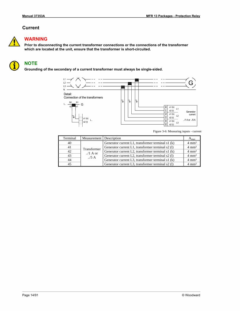
Current
WARNING Prior to disconnecting the current transformer connections or the connections of the transformer which are located at the unit, ensure that the transformer is short-circuited.
NOTE Grounding of the secondary of a current transformer must always be single-sided.
Detail:Connection of the transformers
Generatorcurrent
../1 A or ../5 A
L3L2L1
N
G
S2 S1
s2 (l)s1 (k)
s2L..
....
s1
L.. s1 (k)s2 (l)
s1 (k)s2 (l)
L2
s1 (k)s2 (l)
4243
4041
4445
L1
L3
G
Figure 3-6: Measuring inputs - current
Terminal Measurement Description Amax 40 Generator current L1, transformer terminal s1 (k) 4 mm² 41 Generator current L1, transformer terminal s2 (l) 4 mm² 42 Generator current L2, transformer terminal s1 (k) 4 mm² 43 Generator current L2, transformer terminal s2 (l) 4 mm² 44 Generator current L3, transformer terminal s1 (k) 4 mm² 45
Transformer ../1 A or
../5 A
Generator current L3, transformer terminal s2 (l) 4 mm²
Manual 37353A MFR 13 Packages - Protection Relay
© Woodward Page 15/91
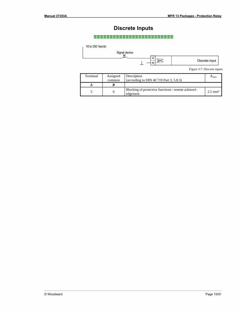
Discrete Inputs ≡≡≡≡≡≡≡≡≡≡≡≡≡≡≡≡≡≡≡≡≡≡≡≡≡
Signal device
Discrete input
AB
18 to 250 Vac/dc
Figure 3-7: Discrete inputs
Terminal Assigned common
Description (according to DIN 40 719 Part 3, 5.8.3)
Amax
A B
5 6 Blocking of protective functions / remote acknowl-edgement 2.5 mm²

Manual 37353A MFR 13 Packages - Protection Relay
Page 16/91 © Woodward
Outputs ≡≡≡≡≡≡≡≡≡≡≡≡≡≡≡≡≡≡≡≡≡≡≡≡≡
Relay Outputs (Standard / Packages GPX / GPX-I / GPY-I / GPY-I-N / K08)
AB
Relay output
Relay outputexternal device
external device
external device
CD
E
max. 250 V AC
Figure 3-8: Relay outputs
Terminal Description Make-contact Amax
Root closing A B
9 10 Relay 1 2.5 mm²
31 32 Relay 8 Pkgs. GPX / GPX-I / GPY-I / GPY-I-N / K08 2.5 mm² Change-over contact
closing Root opening C D E
11 12 13 Relay 2 2.5 mm² 14 15 16 Relay 3 2.5 mm² 19 20 21 Relay 4 Pkgs. GPX / GPX-I / GPY-I / GPY-I-N / K08 2.5 mm² 22 23 24 Relay 5 Pkgs. GPX / GPX-I / GPY-I / GPY-I-N / K08 2.5 mm² 25 26 27 Relay 6 Pkgs. GPX / GPX-I / GPY-I / GPY-I-N / K08 2.5 mm² 28 29 30 Relay 7 Pkgs. GPX / GPX-I / GPY-I / GPY-I-N / K08 2.5 mm²
Pulse Output (Packages GPY-I / GPY-I-N)
BA Pulse output
Open collector
+-
24 V DC
R > 1 kOhm
V
Figure 3-9: Pulse output
Terminal Description Amax A 60 B 61
Pulse output (Open Collector) 2.5 mm²
Manual 37353A MFR 13 Packages - Protection Relay
© Woodward Page 17/91
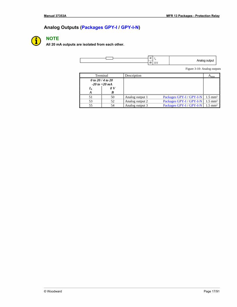
Analog Outputs (Packages GPY-I / GPY-I-N)
NOTE All 20 mA outputs are isolated from each other.
AB
Analog output0 VIA
Figure 3-10: Analog outputs
Terminal Description Amax 0 to 20 / 4 to 20 -20 to +20 mA
IA 0 V A B
51 50 Analog output 1 Packages GPY-I / GPY-I-N 1.5 mm² 53 52 Analog output 2 Packages GPY-I / GPY-I-N 1.5 mm² 55 54 Analog output 3 Packages GPY-I / GPY-I-N 1.5 mm²

Manual 37353A MFR 13 Packages - Protection Relay
Page 18/91 © Woodward
Interface (Packages GPX-I / GPY-I / GPY-I-N / K08) ≡≡≡≡≡≡≡≡≡≡≡≡≡≡≡≡≡≡≡≡≡≡≡≡≡
Modbus Interface
X1 X2 X3 X4 X5
GND
B (in
verte
d)
A (n
on-in
verte
d)
B (in
verte
d)
A (n
on-in
verte
d)
Inte
rface
RS-4
85
Mod
bus
RTU
Slav
e
Figure 3-11: Interfaces
Terminal Description (X1) (X2) (X3) (X4) (X5)
B A GND B A RS-485, Modbus RTU Slave
NOTE The Modbus interface connection may be performed at the terminals X1 through X3 or X3 through X5. The terminals X1 and X4 as well as X2 and X5 are connected internally.

Manual 37353A MFR 13 Packages - Protection Relay
© Woodward Page 19/91
DPC - Direct Configuration Interface
NOTE Configuration with the direct configuration cable DPC (P/N 5417-557) is possible. A laptop/PC, the DPC cable, the program LeoPC1 version 3.1.1 or higher (included on CD Rom with unit), and the proper con-figuration files are required. Please consult the online help installed when the program is installed for a description of the LeoPC1 program and its setup.
WARNING Only the DPC cable may be connected to the DPC interface. If other devices or lines are connected, the unit may be destroyed. Especially the connection of live lines (like phone lines) will destroy the unit.
CAUTION The connection cable delivered with the DPC must be used between DPC and the unit to ensure proper functionality of the unit. An extension or utilization of different cable types for the connection between the unit and DPC may result a malfunction of the unit. This may possibly result in damage to compo-nents of the system. If an extension of the data connection line is required, only the serial cable (RS-232) between DPC and laptop/PC may be extended. It is recommended to use an industry standard ca-ble for this.
NOTE If the parameter "Direct config." is enabled on the control, communication via the CAN bus interface on terminals X1/X5 is disabled. If the control unit detects that the engine is running (ignition speed exceeded), the direct configuration port is disabled.

Manual 37353A MFR 13 Packages - Protection Relay
Page 20/91 © Woodward
Chapter 4. Functional Description
Control Inputs ≡≡≡≡≡≡≡≡≡≡≡≡≡≡≡≡≡≡≡≡≡≡≡≡≡
Blocking of protective
functions / Remote ac-knowledgement
Terminal 5/6
Energizing this discrete input disables various protective functions. This functionality may be desired if the control is used for generator protection. This keeps the control from recognizing fault conditions (i.e. undervoltage, underfrequency) when the generator is not operating. If blocking of these protective functions is not required, the discrete input should not be con-nected to any potential source.
The following protective functions cannot be blocked via this discrete input: • Overvoltage monitoring • Overfrequency monitoring • Zero voltage monitoring • Ground fault monitoring (calculated)
External acknowledgement
of the relays via the discrete input "Blocking of protec-tive functions / remote ac-
knowledgement"
External Clearing ON
If the unit should not automatically reset the relays after the fault is no longer present, the parameter "Auto clearing Relays" must first be configured "OFF" (refer to "Auto Acknowledgement of the Relay" on page 59). OFF ..............Alarms that cannot be blocked will not automatically reset af-
ter the fault condition is no longer present. Pressing the "Clear" button resets the relays.
ON ................All alarm messages are reset if terminals 5/6 ("Blocking of protective functions / remote acknowledgement") are ener-gized. Alarms that cannot be blocked are only reset after the fault is no longer present.
Manual 37353A MFR 13 Packages - Protection Relay
© Woodward Page 21/91
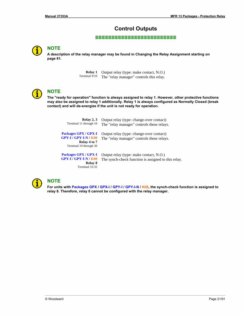
Control Outputs ≡≡≡≡≡≡≡≡≡≡≡≡≡≡≡≡≡≡≡≡≡≡≡≡≡
NOTE A description of the relay manager may be found in Changing the Relay Assignment starting on page 61.
Relay 1 Terminal 9/10
Output relay (type: make contact, N.O.) The "relay manager" controls this relay.
NOTE The "ready for operation" function is always assigned to relay 1. However, other protective functions may also be assigned to relay 1 additionally. Relay 1 is always configured as Normally Closed (break contact) and will de-energize if the unit is not ready for operation.
Relay 2, 3 Terminal 11 through 16
Output relay (type: change-over contact) The "relay manager" controls these relays.
Packages GPX / GPX-I
GPY-I / GPY-I-N / K08 Relay 4 to 7
Terminal 19 through 30
Output relay (type: change-over contact) The "relay manager" controls these relays.
Packages GPX / GPX-I
GPY-I / GPY-I-N / K08 Relay 8
Terminal 31/32
Output relay (type: make contact, N.O.) The synch-check function is assigned to this relay.
NOTE For units with Packages GPX / GPX-I / GPY-I / GPY-I-N / K08, the synch-check function is assigned to relay 8. Therefore, relay 8 cannot be configured with the relay manager.
Manual 37353A MFR 13 Packages - Protection Relay
Page 22/91 © Woodward
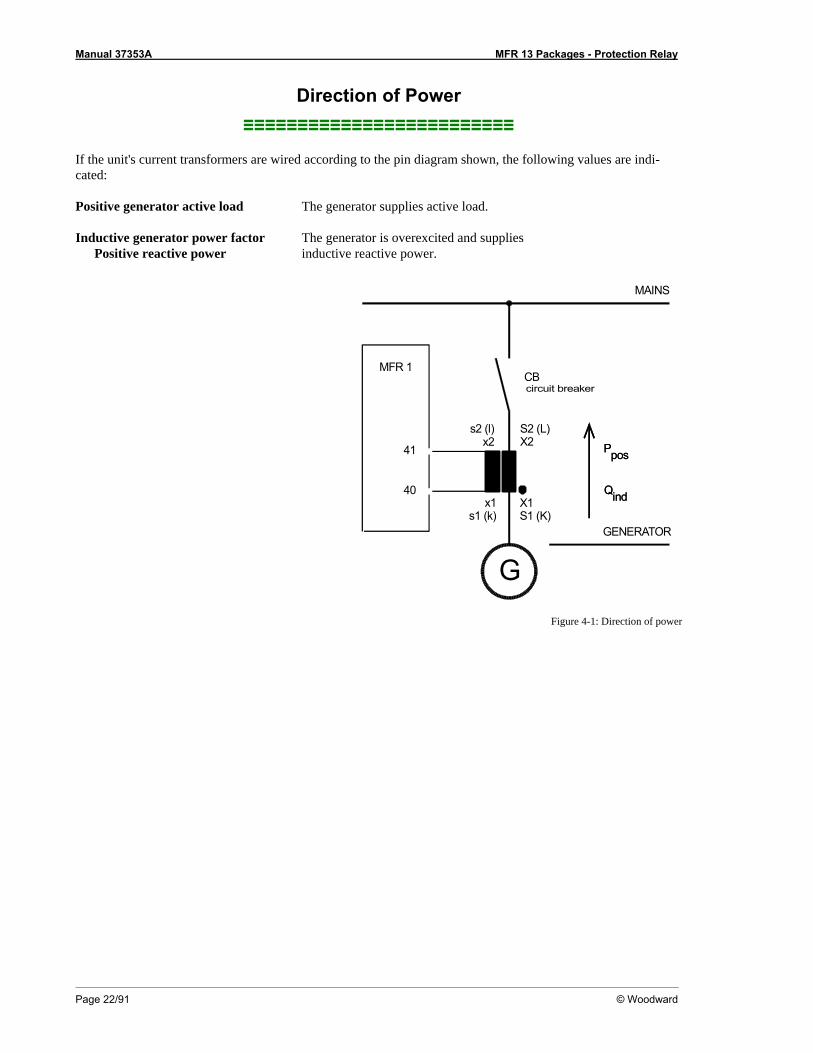
Direction of Power ≡≡≡≡≡≡≡≡≡≡≡≡≡≡≡≡≡≡≡≡≡≡≡≡≡
If the unit's current transformers are wired according to the pin diagram shown, the following values are indi-cated: Positive generator active load The generator supplies active load. Inductive generator power factor The generator is overexcited and supplies Positive reactive power inductive reactive power.
MAINS
G
pospos
PP
indind
GENERATOR
MFR 1CBcircuit breaker
40
41
s2 (l)x2
S2 (L)X2
X1S1 (K)
x1s1 (k)
Figure 4-1: Direction of power
Manual 37353A MFR 13 Packages - Protection Relay
© Woodward Page 23/91
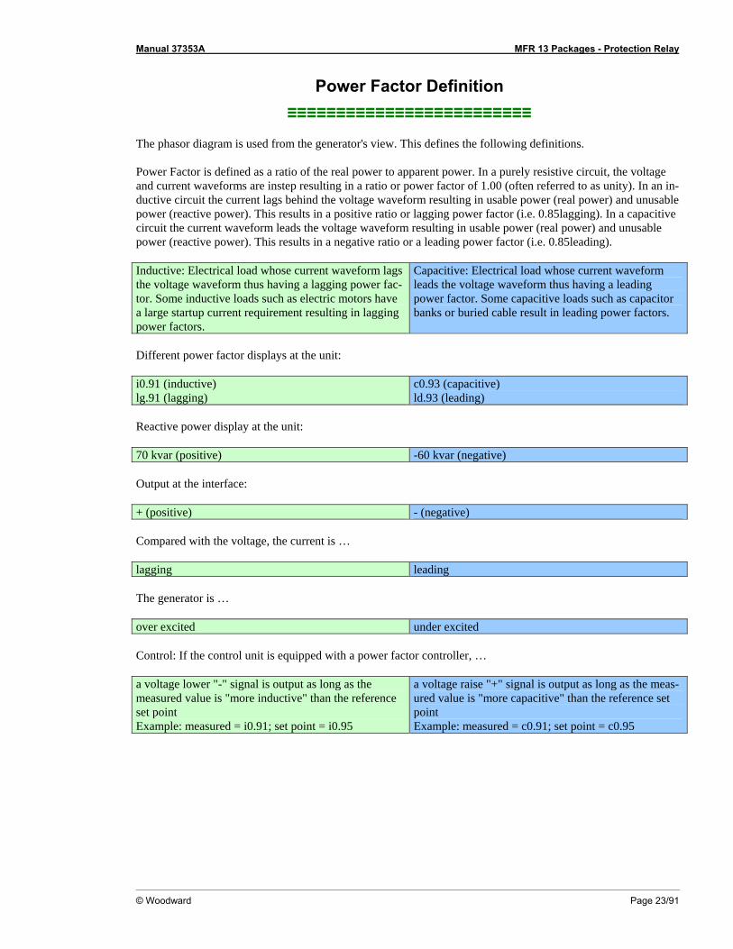
Power Factor Definition ≡≡≡≡≡≡≡≡≡≡≡≡≡≡≡≡≡≡≡≡≡≡≡≡≡
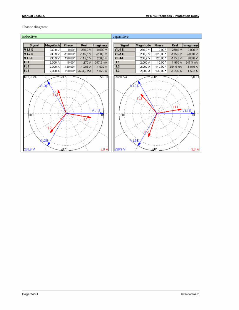
The phasor diagram is used from the generator's view. This defines the following definitions. Power Factor is defined as a ratio of the real power to apparent power. In a purely resistive circuit, the voltage and current waveforms are instep resulting in a ratio or power factor of 1.00 (often referred to as unity). In an in-ductive circuit the current lags behind the voltage waveform resulting in usable power (real power) and unusable power (reactive power). This results in a positive ratio or lagging power factor (i.e. 0.85lagging). In a capacitive circuit the current waveform leads the voltage waveform resulting in usable power (real power) and unusable power (reactive power). This results in a negative ratio or a leading power factor (i.e. 0.85leading). Inductive: Electrical load whose current waveform lags the voltage waveform thus having a lagging power fac-tor. Some inductive loads such as electric motors have a large startup current requirement resulting in lagging power factors.
Capacitive: Electrical load whose current waveform leads the voltage waveform thus having a leading power factor. Some capacitive loads such as capacitor banks or buried cable result in leading power factors.
Different power factor displays at the unit: i0.91 (inductive) lg.91 (lagging)
c0.93 (capacitive) ld.93 (leading)
Reactive power display at the unit: 70 kvar (positive) -60 kvar (negative) Output at the interface: + (positive) - (negative) Compared with the voltage, the current is … lagging leading The generator is … over excited under excited Control: If the control unit is equipped with a power factor controller, … a voltage lower "-" signal is output as long as the measured value is "more inductive" than the reference set point Example: measured = i0.91; set point = i0.95
a voltage raise "+" signal is output as long as the meas-ured value is "more capacitive" than the reference set point Example: measured = c0.91; set point = c0.95
Manual 37353A MFR 13 Packages - Protection Relay
Page 24/91 © Woodward
Phasor diagram: inductive capacitive

Manual 37353A MFR 13 Packages - Protection Relay
© Woodward Page 25/91
Alarms ≡≡≡≡≡≡≡≡≡≡≡≡≡≡≡≡≡≡≡≡≡≡≡≡≡
Alarm Messages Table 4-1 contains a list of all alarm messages that the control may monitor for depending on how the unit is con-figured:
Alarm type Alarm text Overvoltage, level 1 Standard Overvolt.1 Overvoltage, level 2 Standard Overvolt.2 Undervoltage, level 1 Standard Und.volt.1 Undervoltage, level 2 Standard Und.volt.2 Asymmetry Standard Asymmetry Overfrequency, level 1 Standard Overfreq.1 Overfrequency, level 2 Standard Overfreq.2 Underfrequency, level 1 Standard Und.freq.1 Underfrequency, level 2 Standard Und.freq.2 Independent time-overcurrent, level 1 Standard Ov.curr. 1 Independent time-overcurrent, level 2 Standard Ov.curr. 2 Independent time-overcurrent, level 3 Standard Ov.curr. 3 Inverse time-overcurrent Standard I>(invers) Inverse time-overcurrent with voltage restraint Standard I>(invers) Ground fault, calculated, level 1 Standard Earthcur.1 Ground fault, calculated, level 2 Standard Earthcur.2 Overload Standard Overload Reverse-/reduced power Standard Rev. power Unbalanced load Standard Unbalance Reactive power, capacitive Standard React.pow- Reactive power, inductive Standard React.pow+
Table 4-1: Alarm messages
Alarm Acknowledgement A fault/alarm is indicated by the "Alarm" LED. By pressing the "Clear" button, the active faults are acknowledged. The following distinction is made between fault conditions: The fault ... • is still active As long as the fault is still present, it cannot be acknowledged. The flashing "Alarm"
LED on the front panel indicates that the alarm is still active. • is no longer active When the active fault has been eliminated, the flashing "Alarm" LED changes to steady
illumination. If the parameter "Auto clearing displays" is configured "ON", the LED ex-tinguishes after the resetting time has expired. If the parameter "Auto clearing displays" is configured "OFF", the LED is extinguished only after pressing the "Clear" button.
Manual 37353A MFR 13 Packages - Protection Relay
Page 26/91 © Woodward
Chapter 5. Display and Operating Elements
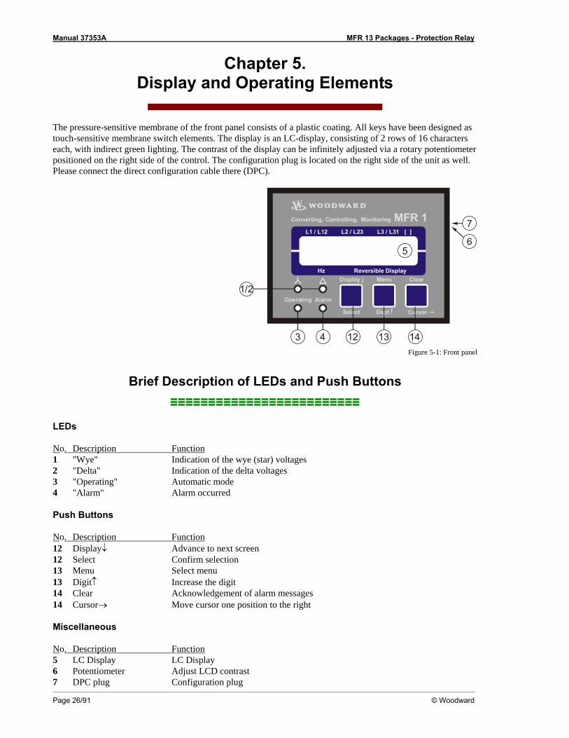
The pressure-sensitive membrane of the front panel consists of a plastic coating. All keys have been designed as touch-sensitive membrane switch elements. The display is an LC-display, consisting of 2 rows of 16 characters each, with indirect green lighting. The contrast of the display can be infinitely adjusted via a rotary potentiometer positioned on the right side of the control. The configuration plug is located on the right side of the unit as well. Please connect the direct configuration cable there (DPC).
MFR 1[ ]L2 / L23L1 / L12 L3 / L31
Hz Reversible Display
Operating
Display Menu
Digit Cursor
Clear
Alarm
Converting, Controlling, Monitoring
Select
14
1/2
131243
5
7
6
Figure 5-1: Front panel
Brief Description of LEDs and Push Buttons ≡≡≡≡≡≡≡≡≡≡≡≡≡≡≡≡≡≡≡≡≡≡≡≡≡
LEDs
No. Description Function 1 "Wye" Indication of the wye (star) voltages 2 "Delta" Indication of the delta voltages 3 "Operating" Automatic mode 4 "Alarm" Alarm occurred
Push Buttons
No. Description Function 12 Display↓ Advance to next screen 12 Select Confirm selection 13 Menu Select menu 13 Digit↑ Increase the digit 14 Clear Acknowledgement of alarm messages 14 Cursor→ Move cursor one position to the right
Miscellaneous
No. Description Function 5 LC Display LC Display 6 Potentiometer Adjust LCD contrast 7 DPC plug Configuration plug
Manual 37353A MFR 13 Packages - Protection Relay
© Woodward Page 27/91
LEDs ≡≡≡≡≡≡≡≡≡≡≡≡≡≡≡≡≡≡≡≡≡≡≡≡≡
NOTE If neither of the "Wye" and "Delta" LEDs is illuminated, the first line of the display indicates the meas-ured currents of the phases.
1 "Wye" Color: Yellow
Indication of the wye voltages
If this LED is illuminated, the values indicated on the display are the wye (star) voltages (phase-neutral).
2 "Delta"
Color: Yellow Indication of the delta voltages
If this LED is illuminated, the values indicated on the display are the delta voltages (phase-phase).
3 "Operation "
Color: Green Operation
This LED is illuminated constantly when the control unit is in the Automatic mode. If this LED is flashing, the control is in the configuration mode.
4 "Alarm"
Color: Red Alarm
This LED flashes as long as a set point limit is exceeded. When all measur-ing values are below the configured set point limit again and "Auto clearing display" is configured "OFF", this LED will change to steady illumination.

Manual 37353A MFR 13 Packages - Protection Relay
Page 28/91 © Woodward
Push Buttons ≡≡≡≡≡≡≡≡≡≡≡≡≡≡≡≡≡≡≡≡≡≡≡≡≡
In order to facilitate the setting of the parameters the buttons are equipped with an "AUTOSCROLL" function while the controller is in the configuration mode. It permits the user to rapidly advance to the next setting and configuration screens, the digits, or the cursor position. The "AUTOSCROLL" function will only be enabled when the user presses and holds the corresponding buttons.
12 Display↓ / Select Color: none
Display↓ / Select
Automatic mode: Display↓ - By pressing this button, the user advances through the display of operating (wye voltages, delta voltages, wire currents) and alarm messages. The "Wye" and "Delta" LEDs are illuminated accordingly.
Configuration: Select - By pressing this button, the user advances to the next configuration screen. If the value originally displayed has been changed via the "Digit↑" or "Cursor→" push buttons, the newly set value is saved by pressing the "Select" push button once. By pressing the button again, the user causes the system to advance to the next configuration screen.
13 Menu / Digit↑
Color: none Menu / Digit↑
Automatic mode: Menu - By pressing this button, the user advances through the messages displayed on the second line of the dis-play. (Various measured values and any alarm messages that have not been cleared are indicated.)
Configuration: Digit↑ - By pressing this button, the position at which the cursor is presently located is increased by one digit. The in-crease is restricted by the permissible limits (see list of pa-rameters included in Appendix E). If the highest permissible number has been reached, the number automatically returns to the lowest permissible number.
14 Clear / Cursor →
Color: none Clear / Cursor →
Automatic mode: Clear - Individual alarm messages are deleted by press-ing this button provided the fault is no longer present.
Configuration: Cursor→ - This button moves the cursor one position to the right. When the cursor reaches the extreme right position it may be returned to the extreme left position by pressing the Cursor→ button again.

Manual 37353A MFR 13 Packages - Protection Relay
© Woodward Page 29/91
LC Display ≡≡≡≡≡≡≡≡≡≡≡≡≡≡≡≡≡≡≡≡≡≡≡≡≡
5 LC Display LC display
Performance values can be monitored from the two-line display, provided that the control is in automatic mode. In configuration mode, the individual parameters are displayed.
Display in Automatic Mode (First Line of the Display: Measured Values)
NOTE The user can scroll through the first display line with the button "Display ↓".
"Wye" = on, "Delta" = off
Wye voltages
230 230 230 V ----------------
"Wye" = off, "Delta" = on Delta voltages
400 400 400 V ----------------
"Wye" = off, "Delta" = off Phase currents
314 314 314 A ----------------
Display in automatic mode, first line: measured values
The following measured values are displayed (depending on the "Wye" and "Delta" LEDs):
- The "Wye" LED is illuminated, and the "Delta" LED is off. The wye (star) voltages (VL1-N, VL2-N and VL3-N) of the four-wire system are indicated. If the application is a three-wire system, the configuration screen "Volt.-Measuring" must be configured to "phase to phase". The "Wye" LED will not illuminate in this application.
- The "Wye" LED is off and the "Delta" LED is illuminated. The delta voltages (VL1-L2, VL2-L3 and VL3-L1) of the phase-to-phase system/phase -neutral system are indicated.
- The "Wye" LED is off and the "Delta" LED is off. The phase currents (IL1, IL2 and IL3) are displayed
Display in Automatic Mode (Second Line of the Display: Measured Values)
NOTE The "Menu" button may be used to scroll through the messages shown on the second line of the dis-play.
---------------- 00.00 xxxxxxxxxx
Display in automatic mode, second line: measured values
The frequency is always indicated in [Hz]. Instead of "xxxxxxxxxx" the following measuring values are indicated: • Power P Unit dynamic in [kW / MW] • Power factor (cos ϕ) Unit dimensionless • Reactive power Q Unit dynamic in [kvar / Mvar] • Apparent power S Unit dynamic in [kVA / MVA] • Active energy W Unit dynamic in [kWh / MWh] • Ground current Ie Unit static in [A] • Synchronizing voltage Unit dyn. in [V/kV]GPX/GPX-I/GPY-I/GPY-I-N/K08 • Synchronizing frequency Unit static in [Hz] GPX/GPX-I/GPY-I/GPY-I-N/K08 • Synchronizing angle Unit static in [°] GPX/GPX-I/GPY-I/GPY-I-N/K08
Manual 37353A MFR 13 Packages - Protection Relay
Page 30/91 © Woodward
Display in Automatic Mode (Second Line of the Display: Alarm Indication)
NOTE The user may scroll through the alarm messages that have occurred with the "Menu" button.
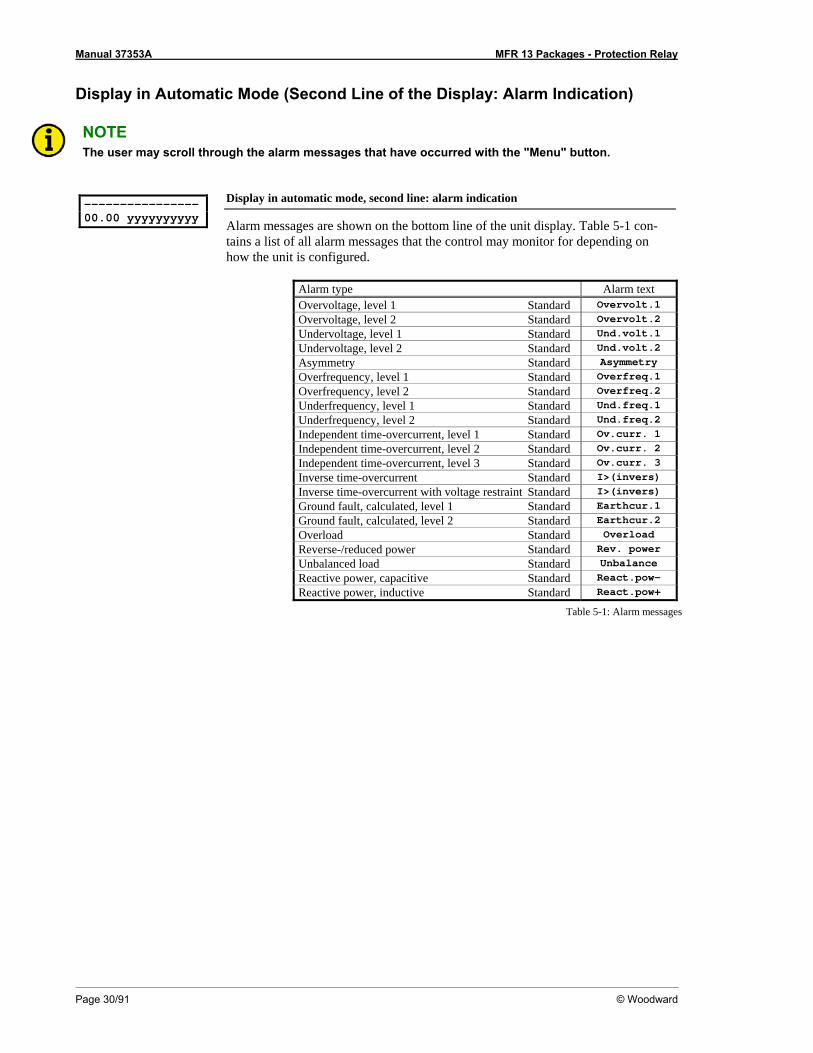
---------------- 00.00 yyyyyyyyyy
Display in automatic mode, second line: alarm indication
Alarm messages are shown on the bottom line of the unit display. Table 5-1 con-tains a list of all alarm messages that the control may monitor for depending on how the unit is configured.
Alarm type Alarm text Overvoltage, level 1 Standard Overvolt.1 Overvoltage, level 2 Standard Overvolt.2 Undervoltage, level 1 Standard Und.volt.1 Undervoltage, level 2 Standard Und.volt.2 Asymmetry Standard Asymmetry Overfrequency, level 1 Standard Overfreq.1 Overfrequency, level 2 Standard Overfreq.2 Underfrequency, level 1 Standard Und.freq.1 Underfrequency, level 2 Standard Und.freq.2 Independent time-overcurrent, level 1 Standard Ov.curr. 1 Independent time-overcurrent, level 2 Standard Ov.curr. 2 Independent time-overcurrent, level 3 Standard Ov.curr. 3 Inverse time-overcurrent Standard I>(invers) Inverse time-overcurrent with voltage restraint Standard I>(invers) Ground fault, calculated, level 1 Standard Earthcur.1 Ground fault, calculated, level 2 Standard Earthcur.2 Overload Standard Overload Reverse-/reduced power Standard Rev. power Unbalanced load Standard Unbalance Reactive power, capacitive Standard React.pow- Reactive power, inductive Standard React.pow+
Table 5-1: Alarm messages

Manual 37353A MFR 13 Packages - Protection Relay
© Woodward Page 31/91
Chapter 6. Configuration
Configuration can be performed via the front panel push buttons and the front panel LC display or using a PC and the PC program LeoPC1 via the serial interface. If direct configuration via a PC is selected, the following baud rate is to be used: • Configuration via direct configuration plug = 9,600 Baud (8 Bit, no parity, 1 stop bit)
CAUTION Please note that configuration only should be done while the system is not in operation.
NOTE A list of all parameters may be found in Appendix E of this manual.
You can advance through the individual parameter screens if you are in configuration mode (simultaneously pressing of "Digit↑" and "Cursor→" push buttons permits access to the configuration mode) by using the "Se-lect" button. If you press and hold the "Select" push button, the scroll function will be activated, allowing for the parameter screens to be advanced through more rapidly. The control unit will permit the operator to reverse up to four previous screens (exception: it is not possible to reverse from the first parameter to the last parameter). To perform the reverse function through the parameter screens, the "Select" and "Cursor→" push buttons must be pressed and released simultaneously. The control unit will revert to automatic mode if an entry isn’t performed, a change made, or any other action performed for 120 seconds.
NOTE There are two different hardware versions described in this operating manual: A 100 V-version [1] and a 400 V-version [4]. The versions vary as far as the configuration screens and the parameter input ranges are concerned. The two types are differentiated by indicating the voltage: ([1] ... or [4] ...).
Adjust Settings: SELECT (ANWAHL)
Configuration mode Button "Select"
After the configuration mode is enabled, the subsequent screens can be viewed and modified within the preset limits. Please note, that by depressing the "Select" but-ton, the following screens are advanced by one screen each. If a parameter is con-figured "OFF", the related screens are not displayed or monitored by the control. Pressing the "Select" button will advance the displayed screen to the next parame-ter.
Manual 37353A MFR 13 Packages - Protection Relay
Page 32/91 © Woodward
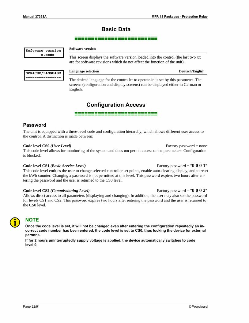
Basic Data ≡≡≡≡≡≡≡≡≡≡≡≡≡≡≡≡≡≡≡≡≡≡≡≡≡
Software version x.xxxx
Software version
This screen displays the software version loaded into the control (the last two xx are for software revisions which do not affect the function of the unit).
SPRACHE/LANGUAGE ----------------
Language selection Deutsch/English
The desired language for the controller to operate in is set by this parameter. The screens (configuration and display screens) can be displayed either in German or English.
Configuration Access ≡≡≡≡≡≡≡≡≡≡≡≡≡≡≡≡≡≡≡≡≡≡≡≡≡
Password The unit is equipped with a three-level code and configuration hierarchy, which allows different user access to the control. A distinction is made between: Code level CS0 (User Level) Factory password = none This code level allows for monitoring of the system and does not permit access to the parameters. Configuration is blocked. Code level CS1 (Basic Service Level) Factory password = "0 0 0 1" This code level entitles the user to change selected controller set points, enable auto-clearing display, and to reset the kWh counter. Changing a password is not permitted at this level. This password expires two hours after en-tering the password and the user is returned to the CS0 level. Code level CS2 (Commissioning Level) Factory password = "0 0 0 2" Allows direct access to all parameters (displaying and changing). In addition, the user may also set the password for levels CS1 and CS2. This password expires two hours after entering the password and the user is returned to the CS0 level.
NOTE Once the code level is set, it will not be changed even after entering the configuration repeatedly an in-correct code number has been entered, the code level is set to CS0, thus locking the device for external persons. If for 2 hours uninterruptedly supply voltage is applied, the device automatically switches to code level 0.
Manual 37353A MFR 13 Packages - Protection Relay
© Woodward Page 33/91
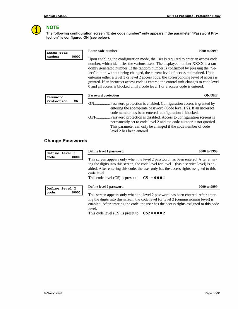
NOTE The following configuration screen "Enter code number" only appears if the parameter "Password Pro-tection" is configured ON (see below).
Enter code number 0000
Enter code number 0000 to 9999
Upon enabling the configuration mode, the user is required to enter an access code number, which identifies the various users. The displayed number XXXX is a ran-domly generated number. If the random number is confirmed by pressing the "Se-lect" button without being changed, the current level of access maintained. Upon entering either a level 1 or level 2 access code, the corresponding level of access is granted. If an incorrect access code is entered the control unit changes to code level 0 and all access is blocked until a code level 1 or 2 access code is entered.
Password Protection ON
Password protection ON/OFF
ON................ Password protection is enabled. Configuration access is granted by entering the appropriate password (Code level 1/2). If an incorrect code number has been entered, configuration is blocked.
OFF.............. Password protection is disabled. Access to configuration screens is permanently set to code level 2 and the code number is not queried. This parameter can only be changed if the code number of code level 2 has been entered.
Change Passwords Define level 1 code 0000
Define level 1 password 0000 to 9999
This screen appears only when the level 2 password has been entered. After enter-ing the digits into this screen, the code level for level 1 (basic service level) is en-abled. After entering this code, the user only has the access rights assigned to this code level. This code level (CS) is preset to CS1 = 0 0 0 1
Define level 2 code 0000
Define level 2 password 0000 to 9999
This screen appears only when the level 2 password has been entered. After enter-ing the digits into this screen, the code level for level 2 (commissioning level) is enabled. After entering the code, the user has the access rights assigned to this code level. This code level (CS) is preset to CS2 = 0 0 0 2

Manual 37353A MFR 13 Packages - Protection Relay
Page 34/91 © Woodward
Direct Configuration ≡≡≡≡≡≡≡≡≡≡≡≡≡≡≡≡≡≡≡≡≡≡≡≡≡
NOTE A direct configuration cable DPC (P/N 5417-557), the LeoPC1 program (supplied with the cable) and the corresponding configuration files are required to perform direct configuration. After the program has been installed, consult the online help for a description of the PC program and its setup.
For configuration of the unit via PC program please proceed as follows: • Install the PC program on your laptop/PC according to the installation manual. • Before the end of the installation you are requested to select the language with which you want to start the PC
program. You can change the language at any time. The selection of the language refers only to language with which the menus and subprograms of the PC program works. This setting will not change the language of the control unit being configured.
• After the installation of the PC program reboot your laptop/PC. • Establish the connection between your laptop/PC and the unit via the DPC. Plug one side to the configuration
plug of the unit and the other side to the COM1 port of your laptop/PC (other possibilities are described in the installation manual).
• You may start the PC program as follows: - by "Start/Program/Woodward/LeoPC" (starting at version 3.1.xxx), or - by a double click on a file ending ".cfg" in the subdirectory "LeoPC".
• After the PC program has been started, establish the communication by pressing the "F2" button. This will es-tablish a data link between the unit and the laptop/PC.
• Start the sub program "Device Parameterization" and adjust the parameter of the unit to your application us-ing this manual.
WARNING If the following parameter "Direct parametr." is configured to "YES", communication via the interface terminals X1 to X5 is disabled (Packages GPX-I / GPY-I / GPY-I-N / K08). If communication is to be re-established via the interface terminals X1 to X5 after the unit is configured, the following parameter must be set to "NO"!
Direct parametr. YES
Direct configuration YES/NO
YES ..............Configuration via the configuration port is enabled. The following conditions must be met in order to carry out configuration via the di-rect configuration cable: - A connection must be established via the direct configuration cable
between the unit and the PC - the Baud rate of the PC program must be set to 9,600 Baud - the corresponding configuration file must be used (file name:
"xxxx-xxxx-yyy-zz.asm", initiated by xxxx-xxxx-yyy-zz.cfg) NO ................Configuration via the direct configuration port is disabled.

Manual 37353A MFR 13 Packages - Protection Relay
© Woodward Page 35/91
Measurement ≡≡≡≡≡≡≡≡≡≡≡≡≡≡≡≡≡≡≡≡≡≡≡≡≡
WARNING The following values must be entered correctly for the generator to be monitored. Failure to do so may lead to incorrect measuring of parameters resulting in damage to or destruction of the generator and/or personal injury or death.
Voltage Measurement Volt.-Measuring ----------------
This screen only affects the dis-played values. The protective functions are defined below.
Voltage measuring Phase to phase/phase neutral
This parameter determines how the voltage is to be measured. If this parameter is set to "Phase to phase", the configuration screen "Volt.-Monitoring" in section Type of Monitoring on page 40 does not appear.
Potential Transformer Configuration
Units with Package GP
Volt.transformer secondary 000V
Potential transformer secondary [1] 50 to 125 V; [4] 50 to 480 V
The potential transformer secondary voltage is set here in V. This parameter is util-ized to calculate the system voltage in the display. For voltages measured without a potential transformer, secondary and primary voltage must be configured the same.
Volt.transformer primary 00.000kV
Potential transformer primary 00.100 to 65.000 kV
The potential transformer primary voltage is set here in kV. This entry is used to show the system voltage in the display.
Example: If a voltage of 400 V is measured without a potential transformer, the secondary transformer voltage
must be configured to 400V and the primary transformer voltage must be configured to 00.400V.
Manual 37353A MFR 13 Packages - Protection Relay
Page 36/91 © Woodward
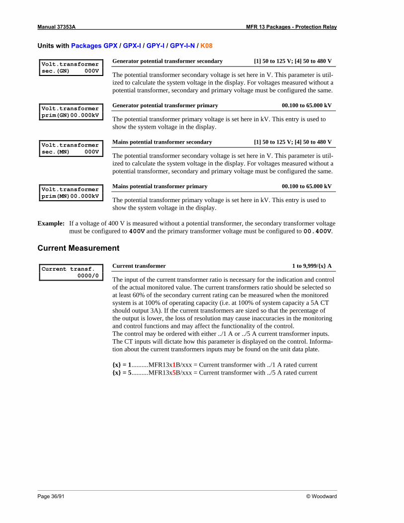
Units with Packages GPX / GPX-I / GPY-I / GPY-I-N / K08
Volt.transformer sec.(GN) 000V
Generator potential transformer secondary [1] 50 to 125 V; [4] 50 to 480 V
The potential transformer secondary voltage is set here in V. This parameter is util-ized to calculate the system voltage in the display. For voltages measured without a potential transformer, secondary and primary voltage must be configured the same.
Volt.transformer prim(GN)00.000kV
Generator potential transformer primary 00.100 to 65.000 kV
The potential transformer primary voltage is set here in kV. This entry is used to show the system voltage in the display.
Volt.transformer sec.(MN) 000V
Mains potential transformer secondary [1] 50 to 125 V; [4] 50 to 480 V
The potential transformer secondary voltage is set here in V. This parameter is util-ized to calculate the system voltage in the display. For voltages measured without a potential transformer, secondary and primary voltage must be configured the same.
Volt.transformer prim(MN)00.000kV
Mains potential transformer primary 00.100 to 65.000 kV
The potential transformer primary voltage is set here in kV. This entry is used to show the system voltage in the display.
Example: If a voltage of 400 V is measured without a potential transformer, the secondary transformer voltage
must be configured to 400V and the primary transformer voltage must be configured to 00.400V.
Current Measurement Current transf. 0000/0
Current transformer 1 to 9,999/{x} A
The input of the current transformer ratio is necessary for the indication and control of the actual monitored value. The current transformers ratio should be selected so at least 60% of the secondary current rating can be measured when the monitored system is at 100% of operating capacity (i.e. at 100% of system capacity a 5A CT should output 3A). If the current transformers are sized so that the percentage of the output is lower, the loss of resolution may cause inaccuracies in the monitoring and control functions and may affect the functionality of the control. The control may be ordered with either ../1 A or ../5 A current transformer inputs. The CT inputs will dictate how this parameter is displayed on the control. Informa-tion about the current transformers inputs may be found on the unit data plate. {x} = 1..........MFR13x1B/xxx = Current transformer with ../1 A rated current {x} = 5..........MFR13x5B/xxx = Current transformer with ../5 A rated current
Manual 37353A MFR 13 Packages - Protection Relay
© Woodward Page 37/91
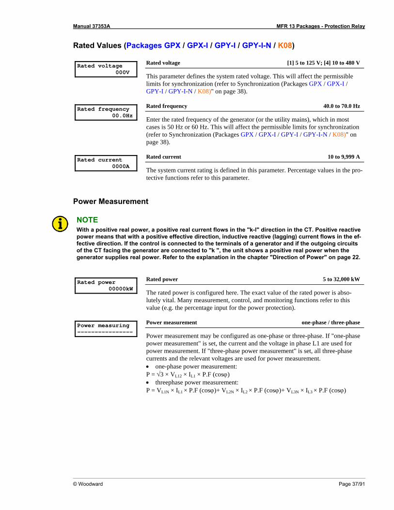
Rated Values (Packages GPX / GPX-I / GPY-I / GPY-I-N / K08) Rated voltage 000V
Rated voltage [1] 5 to 125 V; [4] 10 to 480 V
This parameter defines the system rated voltage. This will affect the permissible limits for synchronization (refer to Synchronization (Packages GPX / GPX-I / GPY-I / GPY-I-N / K08)" on page 38).
Rated frequency 00.0Hz
Rated frequency 40.0 to 70.0 Hz
Enter the rated frequency of the generator (or the utility mains), which in most cases is 50 Hz or 60 Hz. This will affect the permissible limits for synchronization (refer to Synchronization (Packages GPX / GPX-I / GPY-I / GPY-I-N / K08)" on page 38).
Rated current 0000A
Rated current 10 to 9,999 A
The system current rating is defined in this parameter. Percentage values in the pro-tective functions refer to this parameter.
Power Measurement
NOTE With a positive real power, a positive real current flows in the "k-l" direction in the CT. Positive reactive power means that with a positive effective direction, inductive reactive (lagging) current flows in the ef-fective direction. If the control is connected to the terminals of a generator and if the outgoing circuits of the CT facing the generator are connected to "k ", the unit shows a positive real power when the generator supplies real power. Refer to the explanation in the chapter "Direction of Power" on page 22.
Rated power 00000kW
Rated power 5 to 32,000 kW
The rated power is configured here. The exact value of the rated power is abso-lutely vital. Many measurement, control, and monitoring functions refer to this value (e.g. the percentage input for the power protection).
Power measuring ----------------
Power measurement one-phase / three-phase
Power measurement may be configured as one-phase or three-phase. If "one-phase power measurement" is set, the current and the voltage in phase L1 are used for power measurement. If "three-phase power measurement" is set, all three-phase currents and the relevant voltages are used for power measurement. • one-phase power measurement: P = √3 × VL12 × IL1 × P.F (cosϕ) • threephase power measurement: P = VL1N × IL1 × P.F (cosϕ)+ VL2N × IL2 × P.F (cosϕ)+ VL3N × IL3 × P.F (cosϕ)
Manual 37353A MFR 13 Packages - Protection Relay
Page 38/91 © Woodward
Control Functions ≡≡≡≡≡≡≡≡≡≡≡≡≡≡≡≡≡≡≡≡≡≡≡≡≡
Synchronization (Packages GPX / GPX-I / GPY-I / GPY-I-N / K08)
Output of the Signal "Systems are Synchronous"
After the control unit monitors voltages and frequencies are within permissible limits, it will issue a circuit breaker closure command to connect two systems. The closure command has a predefined minimum on time that is output to a relay. Relay 8 is dedicated to this function. The maximum permissible limits are: • Generator System (GN): 75% to 112.5% of the rated voltage • Mains System (MN): 87% to 112.5% of the rated voltage Function "Synchronization of systems" The control unit calculates internally the electrical angle of advance to issue the circuit breaker closure command. The corresponding lead-time remains constant due to the inherent delay of the breaker regardless of the fre-quency differential of the two systems. If the voltage and frequency differential of the two systems are within permissible limits, the breaker closure command may be issued under the following conditions: • The respective monitored voltages of the two systems must be greater than 75 % and less than 112.5 % of the
configured rated voltage. • The monitored voltage differential of the two systems must fall below the configured maximum permissible
voltage differential. • The monitored frequency differential of the two systems must fall below the configured maximum permissi-
ble frequency differential • The electrical angle between two coincident phases must be smaller than the respective permissible error an-
gle (slip-dependent, max. 8 °elec.).
Synchronous Networks
A network is considered as synchronous if the frequency difference between the systems is less than 0.02134 Hz. The unit also issues a breaker closure order for synchronous networks, as long as the electrical angle between the two systems does not exceed the maximum permissible phase angle and the monitored voltage differential is less than the configured maximum permissible voltage differential.
Manual 37353A MFR 13 Packages - Protection Relay
© Woodward Page 39/91
Configuration Screens
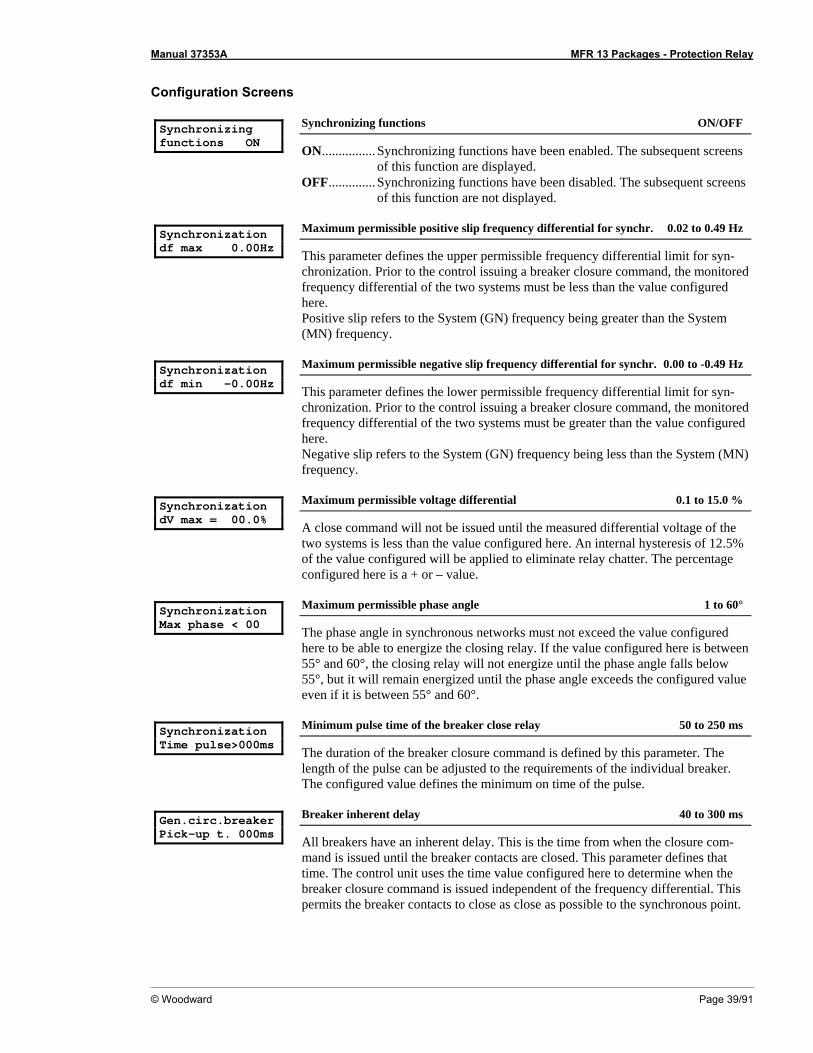
Synchronizing functions ON
Synchronizing functions ON/OFF
ON................ Synchronizing functions have been enabled. The subsequent screens of this function are displayed.
OFF.............. Synchronizing functions have been disabled. The subsequent screens of this function are not displayed.
Synchronization df max 0.00Hz
Maximum permissible positive slip frequency differential for synchr. 0.02 to 0.49 Hz
This parameter defines the upper permissible frequency differential limit for syn-chronization. Prior to the control issuing a breaker closure command, the monitored frequency differential of the two systems must be less than the value configured here. Positive slip refers to the System (GN) frequency being greater than the System (MN) frequency.
Synchronization df min -0.00Hz
Maximum permissible negative slip frequency differential for synchr. 0.00 to -0.49 Hz
This parameter defines the lower permissible frequency differential limit for syn-chronization. Prior to the control issuing a breaker closure command, the monitored frequency differential of the two systems must be greater than the value configured here. Negative slip refers to the System (GN) frequency being less than the System (MN) frequency.
Synchronization dV max = 00.0%
Maximum permissible voltage differential 0.1 to 15.0 %
A close command will not be issued until the measured differential voltage of the two systems is less than the value configured here. An internal hysteresis of 12.5% of the value configured will be applied to eliminate relay chatter. The percentage configured here is a + or – value.
Synchronization Max phase < 00
Maximum permissible phase angle 1 to 60°
The phase angle in synchronous networks must not exceed the value configured here to be able to energize the closing relay. If the value configured here is between 55° and 60°, the closing relay will not energize until the phase angle falls below 55°, but it will remain energized until the phase angle exceeds the configured value even if it is between 55° and 60°.
Synchronization Time pulse>000ms
Minimum pulse time of the breaker close relay 50 to 250 ms
The duration of the breaker closure command is defined by this parameter. The length of the pulse can be adjusted to the requirements of the individual breaker. The configured value defines the minimum on time of the pulse.
Gen.circ.breaker Pick-up t. 000ms
Breaker inherent delay 40 to 300 ms
All breakers have an inherent delay. This is the time from when the closure com-mand is issued until the breaker contacts are closed. This parameter defines that time. The control unit uses the time value configured here to determine when the breaker closure command is issued independent of the frequency differential. This permits the breaker contacts to close as close as possible to the synchronous point.
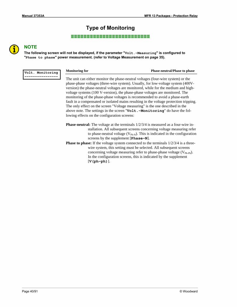
Manual 37353A MFR 13 Packages - Protection Relay
Page 40/91 © Woodward
Type of Monitoring ≡≡≡≡≡≡≡≡≡≡≡≡≡≡≡≡≡≡≡≡≡≡≡≡≡
NOTE The following screen will not be displayed, if the parameter "Volt.-Measuring" is configured to "Phase to phase" power measurement. (refer to Voltage Measurement on page 35).
Volt. Monitoring ----------------
Monitoring for Phase-neutral/Phase to phase
The unit can either monitor the phase-neutral voltages (four-wire system) or the phase-phase voltages (three-wire system). Usually, for low-voltage system (400V-version) the phase-neutral voltages are monitored, while for the medium and high-voltage systems (100 V-version), the phase-phase voltages are monitored. The monitoring of the phase-phase voltages is recommended to avoid a phase-earth fault in a compensated or isolated mains resulting in the voltage protection tripping. The only effect on the screen "Voltage measuring" is the one described in the above note. The settings in the screen "Volt.-Monitoring" do have the fol-lowing effects on the configuration screens: Phase-neutral: The voltage at the terminals 1/2/3/4 is measured as a four-wire in-
stallation. All subsequent screens concerning voltage measuring refer to phase-neutral voltage (VPh-N). This is indicated in the configuration screens by the supplement [Phase-N].
Phase to phase: If the voltage system connected to the terminals 1/2/3/4 is a three-wire system, this setting must be selected. All subsequent screens concerning voltage measuring refer to phase-phase voltage (VPh-Ph). In the configuration screens, this is indicated by the supplement [V(ph-ph)].
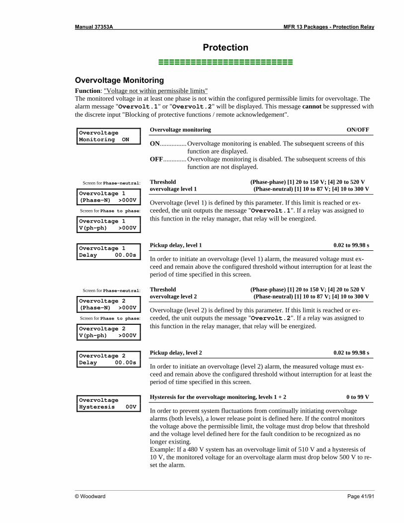
Manual 37353A MFR 13 Packages - Protection Relay
© Woodward Page 41/91
Protection ≡≡≡≡≡≡≡≡≡≡≡≡≡≡≡≡≡≡≡≡≡≡≡≡≡
Overvoltage Monitoring Function: "Voltage not within permissible limits" The monitored voltage in at least one phase is not within the configured permissible limits for overvoltage. The alarm message "Overvolt.1" or "Overvolt.2" will be displayed. This message cannot be suppressed with the discrete input "Blocking of protective functions / remote acknowledgement". Overvoltage Monitoring ON
Overvoltage monitoring ON/OFF
ON................ Overvoltage monitoring is enabled. The subsequent screens of this function are displayed.
OFF.............. Overvoltage monitoring is disabled. The subsequent screens of this function are not displayed.
Screen for Phase-neutral:
Overvoltage 1 (Phase-N) >000V
Screen for Phase to phase:
Overvoltage 1 V(ph-ph) >000V
Threshold (Phase-phase) [1] 20 to 150 V; [4] 20 to 520 V overvoltage level 1 (Phase-neutral) [1] 10 to 87 V; [4] 10 to 300 V
Overvoltage (level 1) is defined by this parameter. If this limit is reached or ex-ceeded, the unit outputs the message "Overvolt.1". If a relay was assigned to this function in the relay manager, that relay will be energized.
Overvoltage 1 Delay 00.00s
Pickup delay, level 1 0.02 to 99.98 s
In order to initiate an overvoltage (level 1) alarm, the measured voltage must ex-ceed and remain above the configured threshold without interruption for at least the period of time specified in this screen.
Screen for Phase-neutral:
Overvoltage 2 (Phase-N) >000V
Screen for Phase to phase:
Overvoltage 2 V(ph-ph) >000V
Threshold (Phase-phase) [1] 20 to 150 V; [4] 20 to 520 V overvoltage level 2 (Phase-neutral) [1] 10 to 87 V; [4] 10 to 300 V
Overvoltage (level 2) is defined by this parameter. If this limit is reached or ex-ceeded, the unit outputs the message "Overvolt.2". If a relay was assigned to this function in the relay manager, that relay will be energized.
Overvoltage 2 Delay 00.00s
Pickup delay, level 2 0.02 to 99.98 s
In order to initiate an overvoltage (level 2) alarm, the measured voltage must ex-ceed and remain above the configured threshold without interruption for at least the period of time specified in this screen.
Overvoltage Hysteresis 00V
Hysteresis for the overvoltage monitoring, levels 1 + 2 0 to 99 V
In order to prevent system fluctuations from continually initiating overvoltage alarms (both levels), a lower release point is defined here. If the control monitors the voltage above the permissible limit, the voltage must drop below that threshold and the voltage level defined here for the fault condition to be recognized as no longer existing. Example: If a 480 V system has an overvoltage limit of 510 V and a hysteresis of 10 V, the monitored voltage for an overvoltage alarm must drop below 500 V to re-set the alarm.

Manual 37353A MFR 13 Packages - Protection Relay
Page 42/91 © Woodward
Undervoltage Monitoring Function: "Voltage not within permissible limits" The monitored voltage in at least one phase is not within the configured permissible limits for undervoltage. The alarm message "Und.volt.1" or "Und.volt.2" will be displayed. This message cannot be suppressed with the discrete input "Blocking of protective functions / remote acknowledgement". Undervoltage Monitoring ON
Undervoltage monitoring ON/OFF
ON ................Undervoltage monitoring is enabled. The subsequent screens of this function are displayed.
OFF ..............Undervoltage monitoring is disabled. The subsequent screens of this function are not displayed.
Screen for Phase-neutral:
Undervoltage 1 (Phase-N) <000V
Screen for Phase to phase:
Undervoltage 1 V(ph-ph) <000V
Threshold (Phase-phase) [1] 20 to 150 V; [4] 20 to 520 V undervoltage level 1 (Phase-neutral) [1] 10 to 87 V; [4] 10 to 300 V
Undervoltage (level 1) is defined by this parameter. If this limit is reached or fallen below, the unit outputs the message " Und.volt.1". If a relay was assigned to this function in the relay manager, that relay will be energized.
Undervoltage 1 Delay 00.00s
Pickup delay, level 1 0.02 to 99.98 s
In order to initiate an undervoltage (level 1) alarm, the measured voltage must fall below and remain below the configured threshold without interruption for at least the period of time specified in this screen.
Screen for Phase-neutral:
Undervoltage 2 (Phase-N) <000V
Screen for Phase to phase:
Undervoltage 2 V(ph-ph) <000V
Threshold (Phase-phase) [1] 20 to 150 V; [4] 20 to 520 V undervoltage level 2 (Phase-neutral) [1] 10 to 87 V; [4] 10 to 300 V
Undervoltage (level 2) is defined by this parameter. If this limit is reached or fallen below, the unit outputs the message " Und.volt.2". If a relay was assigned to this function in the relay manager, that relay will be energized.
Undervoltage 2 Delay 00.00s
Pickup delay, level 2 0.02 to 99.98 s
In order to initiate an undervoltage (level 2) alarm, the measured voltage must fall below and remain below the configured threshold without interruption for at least the period of time specified in this screen.
Undervoltage Hysteresis 00V
Hysteresis for the undervoltage monitoring, levels 1 + 2 0 to 99 V
In order to prevent system fluctuations from continually initiating undervoltage alarms (both levels), a higher release point is defined here. If the control monitors the voltage below the permissible limit, the voltage must rise above that threshold and the voltage level defined here for the fault condition to be recognized as no longer existing. Example: If a 480 V system has an undervoltage limit of 440 V and a hysteresis of 10 V, the monitored voltage for an overvoltage alarm must rise above 450 V to re-set the alarm.
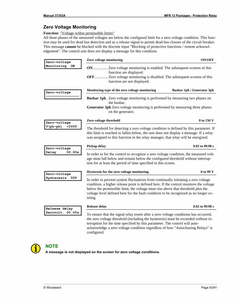
Manual 37353A MFR 13 Packages - Protection Relay
© Woodward Page 43/91
Zero Voltage Monitoring Function: "Voltage within permissible limits" All three phases of the measured voltages are below the configured limit for a zero voltage condition. This func-tion may be used for dead bus detection and as a release signal to permit dead bus closure of the circuit breaker. This message cannot be blocked with the discrete input "Blocking of protective functions / remote acknowl-edgement". The control unit does not display a message for this condition. Zero-voltage Monitoring ON
Zero voltage monitoring ON/OFF
ON................ Zero voltage monitoring is enabled. The subsequent screens of this function are displayed.
OFF.............. Zero voltage monitoring is disabled. The subsequent screens of this function are not displayed.
Zero-voltage ----------------
Monitoring type of the zero voltage monitoring Busbar 1ph / Generator 3ph
Busbar 1ph.. Zero voltage monitoring is performed by measuring two phases on the busbar.
Generator 3ph Zero voltage monitoring is performed by measuring three phases on the generator.
Zero-voltage V(ph-ph) <000V
Zero voltage threshold 8 to 150 V
The threshold for detecting a zero voltage condition is defined by this parameter. If this limit is reached or fallen below, the unit does not display a message. If a relay was assigned to this function in the relay manager, that relay will be energized.
Zero-voltage Delay 00.00s
Pickup delay 0.02 to 99.98 s
In order to for the control to recognize a zero voltage condition, the measured volt-age must fall below and remain below the configured threshold without interrup-tion for at least the period of time specified in this screen.
Zero-voltage Hysteresis 00V
Hysteresis for the zero voltage monitoring 0 to 99 V
In order to prevent system fluctuations from continually initiating a zero voltage condition, a higher release point is defined here. If the control monitors the voltage below the permissible limit, the voltage must rise above that threshold plus the voltage level defined here for the fault condition to be recognized as no longer ex-isting.
Release delay Zerovolt. 00.00s
Release delay 0.02 to 99.98 s
To ensure that the signal relay resets after a zero voltage conditions has occurred, the zero voltage threshold (including the hysteresis) must be exceeded without in-terruption for the time specified by this parameter. The control will auto-acknowledge a zero voltage condition regardless of how "Autoclearing Relays" is configured.
NOTE A message is not displayed on the screen for zero voltage conditions.

Manual 37353A MFR 13 Packages - Protection Relay
Page 44/91 © Woodward
Voltage Asymmetry Monitoring The phase-phase voltages are monitored. Function "Voltage asymmetry not within permissible limits" The monitored phase-phase voltage differential in the three phases is not within the configured permissible limits for asymmetry (asymmetric voltage vectors; the threshold corresponding to the differential value). The alarm message "Asymmetry" will be displayed. This message can be suppressed with the discrete input "Blocking of protective functions / remote acknowledgement". Asymmetry- Monitoring ON
Asymmetry monitoring ON/OFF
ON ................Voltage asymmetry monitoring is enabled. The subsequent screens of this function are displayed.
OFF ..............Voltage asymmetry monitoring is disabled. The subsequent screens of this function are not displayed.
Asymmetry Response v. 00V.
Maximum permissible asymmetry 0 to 99 V
The maximum voltage asymmetry is defined by this parameter. If this limit is reached or exceeded, the unit outputs the message "Asymmetry". If a relay was assigned to this function in the relay manager, that relay will be energized.
Asymmetry Delay 00.00s
Pickup delay 0.02 to 99.98 s
In order to initiate a voltage asymmetry alarm, the measured voltage differential must rise above and remain above the configured threshold without interruption for at least the period of time specified in this screen.
Asymmetry Hysteresis 00V
Hysteresis for the asymmetry monitoring 0 to 99 V
In order to prevent system fluctuations from continually initiating a voltage asym-metry fault, a lower release point is defined here. If the control monitors the voltage asymmetry beyond the permissible limit, the voltage differential must fall below that threshold plus the voltage level defined here for the fault condition to be rec-ognized as no longer existing.
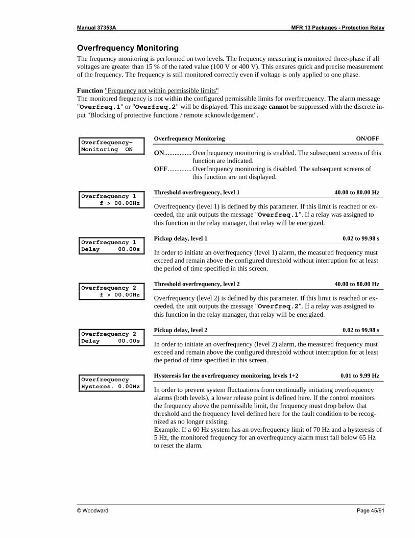
Manual 37353A MFR 13 Packages - Protection Relay
© Woodward Page 45/91
Overfrequency Monitoring The frequency monitoring is performed on two levels. The frequency measuring is monitored three-phase if all voltages are greater than 15 % of the rated value (100 V or 400 V). This ensures quick and precise measurement of the frequency. The frequency is still monitored correctly even if voltage is only applied to one phase. Function "Frequency not within permissible limits" The monitored frequency is not within the configured permissible limits for overfrequency. The alarm message "Overfreq.1" or "Overfreq.2" will be displayed. This message cannot be suppressed with the discrete in-put "Blocking of protective functions / remote acknowledgement". Overfrequency- Monitoring ON
Overfrequency Monitoring ON/OFF
ON................ Overfrequency monitoring is enabled. The subsequent screens of this function are indicated.
OFF.............. Overfrequency monitoring is disabled. The subsequent screens of this function are not displayed.
Overfrequency 1 f > 00.00Hz
Threshold overfrequency, level 1 40.00 to 80.00 Hz
Overfrequency (level 1) is defined by this parameter. If this limit is reached or ex-ceeded, the unit outputs the message "Overfreq.1". If a relay was assigned to this function in the relay manager, that relay will be energized.
Overfrequency 1 Delay 00.00s
Pickup delay, level 1 0.02 to 99.98 s
In order to initiate an overfrequency (level 1) alarm, the measured frequency must exceed and remain above the configured threshold without interruption for at least the period of time specified in this screen.
Overfrequency 2 f > 00.00Hz
Threshold overfrequency, level 2 40.00 to 80.00 Hz
Overfrequency (level 2) is defined by this parameter. If this limit is reached or ex-ceeded, the unit outputs the message "Overfreq.2". If a relay was assigned to this function in the relay manager, that relay will be energized.
Overfrequency 2 Delay 00.00s
Pickup delay, level 2 0.02 to 99.98 s
In order to initiate an overfrequency (level 2) alarm, the measured frequency must exceed and remain above the configured threshold without interruption for at least the period of time specified in this screen.
Overfrequency Hysteres. 0.00Hz
Hysteresis for the overfrequency monitoring, levels 1+2 0.01 to 9.99 Hz
In order to prevent system fluctuations from continually initiating overfrequency alarms (both levels), a lower release point is defined here. If the control monitors the frequency above the permissible limit, the frequency must drop below that threshold and the frequency level defined here for the fault condition to be recog-nized as no longer existing. Example: If a 60 Hz system has an overfrequency limit of 70 Hz and a hysteresis of 5 Hz, the monitored frequency for an overfrequency alarm must fall below 65 Hz to reset the alarm.

Manual 37353A MFR 13 Packages - Protection Relay
Page 46/91 © Woodward
Underfrequency Monitoring The frequency monitoring is performed on two levels. The frequency measuring is monitored three-phase if all voltages are greater than 15 % of the rated value (100 V or 400 V). This ensures quick and precise measurement of the frequency. The frequency is still monitored correctly even if voltage is only applied to one phase. Function "Frequency not within permissible limits" The monitored frequency is not within the configured permissible limits for overfrequency. The alarm message "Und.freq.1" or "Und.freq.2" will be displayed. This message can be suppressed with the discrete input "Blocking of protective functions / remote acknowledgement". Underfrequency- Monitoring ON
Underfrequency Monitoring ON/OFF
ON ................Underfrequency monitoring is enabled. The subsequent screens of this function are indicated.
OFF ..............Underfrequency monitoring is disabled. The subsequent screens of this function are not displayed.
Underfrequency 1 f < 00.00Hz
Threshold underfrequency, level 1 40.00 to 80.00 Hz
Underfrequency (level 1) is defined by this parameter. If this limit is reached or fallen below, the unit outputs the message "Und.freq.1". If a relay was assigned to this function in the relay manager, that relay will be energized.
Underfrequency 1 Delay 00.00s
Pickup delay, level 1 0.02 to 99.98 s
In order to initiate an underfrequency (level 1) alarm, the measured frequency must fall below and remain below the configured threshold without interruption for at least the period of time specified in this screen.
Underfrequency 2 f < 00.00Hz
Threshold underfrequency, level 2 40.00 to 80.00 Hz
Underfrequency (level 2) is defined by this parameter. If this limit is reached or fallen below, the unit outputs the message "Und.freq.2". If a relay was assigned to this function in the relay manager, that relay will be energized.
Underfrequency 2 Delay 00.00s
Pickup delay, level 2 0.02 to 99.98 s
In order to initiate an underfrequency (level 2) alarm, the measured frequency must fall below and remain below the configured threshold without interruption for at least the period of time specified in this screen.
Underfrequency Hysteres. 0.00Hz
Hysteresis for the underfrequency monitoring, levels 1 + 2 0.01 to 9.99 Hz
In order to prevent system fluctuations from continually initiating underfrequency alarms (both levels), a higher release point is defined here. If the control monitors the frequency below the permissible limit, the frequency must rise above that threshold and the frequency level defined here for the fault condition to be recog-nized as no longer existing. Example: If a 60 Hz system has an underfrequency limit of 50 Hz and a hysteresis of 5 Hz, the monitored frequency for an overfrequency alarm must rise above 55 Hz to reset the alarm.
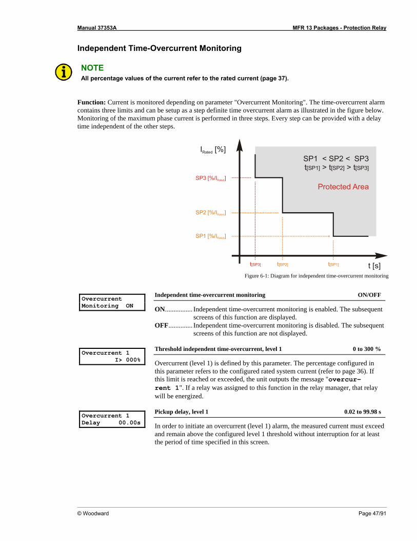
Manual 37353A MFR 13 Packages - Protection Relay
© Woodward Page 47/91
Independent Time-Overcurrent Monitoring
NOTE All percentage values of the current refer to the rated current (page 37).
Function: Current is monitored depending on parameter "Overcurrent Monitoring". The time-overcurrent alarm contains three limits and can be setup as a step definite time overcurrent alarm as illustrated in the figure below. Monitoring of the maximum phase current is performed in three steps. Every step can be provided with a delay time independent of the other steps.
t [s]
SP3 [%/I ]Rated
SP2 [%/I ]Rated
SP1 [%/I ]Rated
IRated [%]
Protected Area
SP1 < SP2 < SP3t > t > t[SP1] [SP2] [SP3]
t[SP3] t[SP2] t[SP1]
Figure 6-1: Diagram for independent time-overcurrent monitoring
Overcurrent Monitoring ON
Independent time-overcurrent monitoring ON/OFF
ON................ Independent time-overcurrent monitoring is enabled. The subsequent screens of this function are displayed.
OFF.............. Independent time-overcurrent monitoring is disabled. The subsequent screens of this function are not displayed.
Overcurrent 1 I> 000%
Threshold independent time-overcurrent, level 1 0 to 300 %
Overcurrent (level 1) is defined by this parameter. The percentage configured in this parameter refers to the configured rated system current (refer to page 36). If this limit is reached or exceeded, the unit outputs the message "overcur-rent 1". If a relay was assigned to this function in the relay manager, that relay will be energized.
Overcurrent 1 Delay 00.00s
Pickup delay, level 1 0.02 to 99.98 s
In order to initiate an overcurrent (level 1) alarm, the measured current must exceed and remain above the configured level 1 threshold without interruption for at least the period of time specified in this screen.
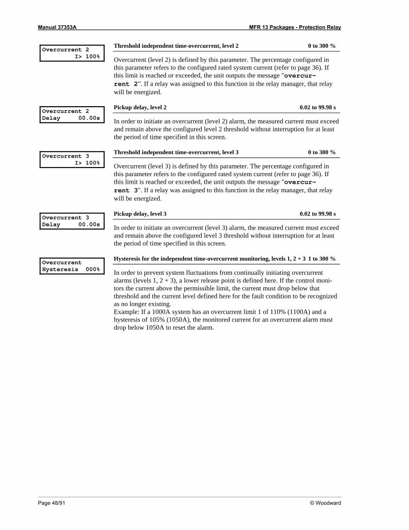
Manual 37353A MFR 13 Packages - Protection Relay
Page 48/91 © Woodward
Overcurrent 2 I> 100%
Threshold independent time-overcurrent, level 2 0 to 300 %
Overcurrent (level 2) is defined by this parameter. The percentage configured in this parameter refers to the configured rated system current (refer to page 36). If this limit is reached or exceeded, the unit outputs the message "overcur-rent 2". If a relay was assigned to this function in the relay manager, that relay will be energized.
Overcurrent 2 Delay 00.00s
Pickup delay, level 2 0.02 to 99.98 s
In order to initiate an overcurrent (level 2) alarm, the measured current must exceed and remain above the configured level 2 threshold without interruption for at least the period of time specified in this screen.
Overcurrent 3 I> 100%
Threshold independent time-overcurrent, level 3 0 to 300 %
Overcurrent (level 3) is defined by this parameter. The percentage configured in this parameter refers to the configured rated system current (refer to page 36). If this limit is reached or exceeded, the unit outputs the message "overcur-rent 3". If a relay was assigned to this function in the relay manager, that relay will be energized.
Overcurrent 3 Delay 00.00s
Pickup delay, level 3 0.02 to 99.98 s
In order to initiate an overcurrent (level 3) alarm, the measured current must exceed and remain above the configured level 3 threshold without interruption for at least the period of time specified in this screen.
Overcurrent Hysteresis 000%
Hysteresis for the independent time-overcurrent monitoring, levels 1, 2 + 3 1 to 300 %
In order to prevent system fluctuations from continually initiating overcurrent alarms (levels 1, 2 + 3), a lower release point is defined here. If the control moni-tors the current above the permissible limit, the current must drop below that threshold and the current level defined here for the fault condition to be recognized as no longer existing. Example: If a 1000A system has an overcurrent limit 1 of 110% (1100A) and a hysteresis of 105% (1050A), the monitored current for an overcurrent alarm must drop below 1050A to reset the alarm.
Manual 37353A MFR 13 Packages - Protection Relay
© Woodward Page 49/91
Inverse Time-Overcurrent Monitoring
NOTE All percentage indications of the current refer to the rated current (see page 37).
Function: Monitoring of overcurrents including inversely proportional time dependent tripping characteristic. The selected trip curve defines the tripping time according to the measured current. The tripping time will be de-creased according to a defined curve the higher the measured current is. According to IEC 255 three different characteristics are available. Normal inverse: ][*
1)/(14.0
02.0st
IIt p
P −=
Very inverse: ][*
1)/(5.13 st
IIt p
P −=
Extremely inverse: ][*
1)/(80
2 stII
t pP −
=
Formula definitions: t: tripping time tp time set point value I fault current / monitored current In rated (nominal) current Ip current set point value If t is greater than 162 s the system trips at 162 s. If t is lower than tmin the tripping time is tmin. The reaction time for tmin depends on the time it takes to monitor the fault and the operating time of the relays. tmin is at least 20 ms. Please consider during configuration: for Istart: Istart > In and Istart > Ip for Ip the smaller Ip is, the steeper is the slope of the tripping curve
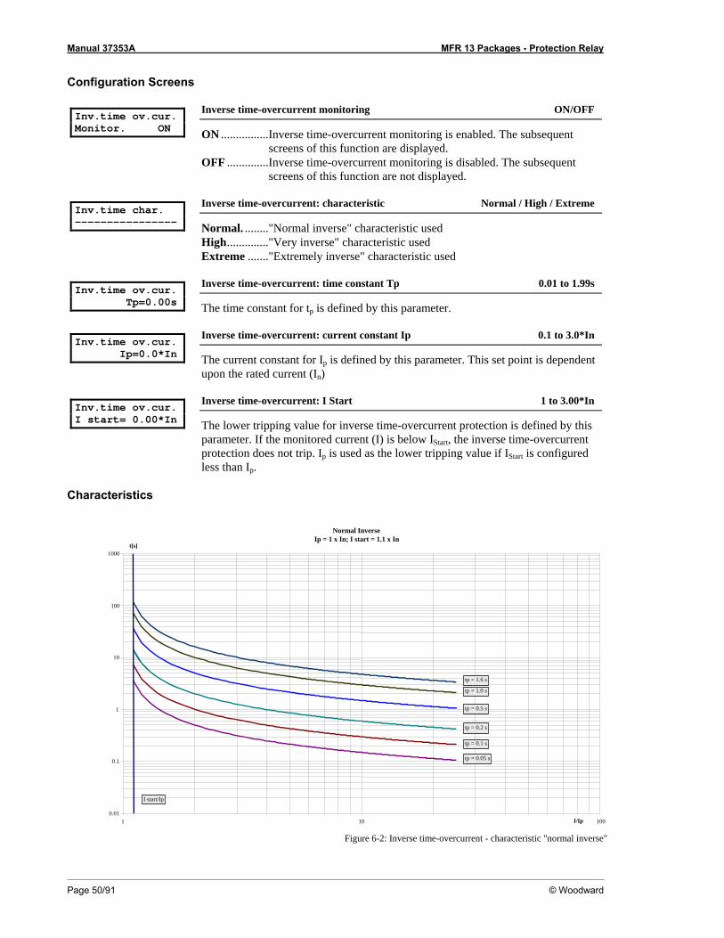
Manual 37353A MFR 13 Packages - Protection Relay
Page 50/91 © Woodward
Configuration Screens Inv.time ov.cur. Monitor. ON
Inverse time-overcurrent monitoring ON/OFF
ON ................Inverse time-overcurrent monitoring is enabled. The subsequent screens of this function are displayed.
OFF ..............Inverse time-overcurrent monitoring is disabled. The subsequent screens of this function are not displayed.
Inv.time char. ----------------
Inverse time-overcurrent: characteristic Normal / High / Extreme
Normal. ........"Normal inverse" characteristic used High.............."Very inverse" characteristic used Extreme ......."Extremely inverse" characteristic used
Inv.time ov.cur. Tp=0.00s
Inverse time-overcurrent: time constant Tp 0.01 to 1.99s
The time constant for tp is defined by this parameter. Inv.time ov.cur. Ip=0.0*In
Inverse time-overcurrent: current constant Ip 0.1 to 3.0*In
The current constant for Ip is defined by this parameter. This set point is dependent upon the rated current (In)
Inv.time ov.cur. I start= 0.00*In
Inverse time-overcurrent: I Start 1 to 3.00*In
The lower tripping value for inverse time-overcurrent protection is defined by this parameter. If the monitored current (I) is below IStart, the inverse time-overcurrent protection does not trip. Ip is used as the lower tripping value if IStart is configured less than Ip.
Characteristics
Normal InverseIp = 1 x In; I start = 1.1 x In
0.01
0.1
1
10
100
1000
1 10 100I/Ip
t[s]
tp = 1.6 s
tp = 1.0 s
tp = 0.5 s
tp = 0.2 s
tp = 0.1 s
tp = 0.05 s
I start/Ip
Figure 6-2: Inverse time-overcurrent - characteristic "normal inverse"

Manual 37353A MFR 13 Packages - Protection Relay
© Woodward Page 51/91
Very Inverse
Ip = In; I start = 1.1 x In
0.01
0.1
1
10
100
1000
1 10 100I/Ip
t[s]
tp = 1.0 s tp = 0.5 s tp = 0.2 s tp = 0.1 s tp = 0.05 s
tp = 1.6 s
I start/Ip
Figure 6-3: Inverse time-overcurrent - characteristic "very inverse"
Extremely Inverse
Ip = In; I start = 1.1 x In
0.01
0.1
1
10
100
1000
1 10 100I/Ip
t[s]
tp = 1.0 s tp = 0.5 s tp = 0.2 s
tp = 0.1 s tp = 0.05 s
tp = 1.6 s
I start/Ip
Figure 6-4: Inverse time-overcurrent - characteristic "extremely inverse"

Manual 37353A MFR 13 Packages - Protection Relay
Page 52/91 © Woodward
Inverse Time-Overcurrent Monitoring with Voltage Restraint
NOTE This monitoring function is an additional functionality for the inverse time overcurrent monitoring func-tion. If the inverse time overcurrent monitoring is disabled, time-overcurrent monitoring with voltage restraint is disabled too. All percentage indications of the current are in relation to the rated current (see page 37).
Function: This function is recommended for a generator that must be monitored with droop excitation and pre-cautions for short-circuit excitation (e.g. supplementary components) are not available. A short-circuit close to the terminal may be caused due to the low voltage excitation cannot be maintained. As a result, the unit cannot maintain power in order to initiate a voltage independent overcurrent delay. The voltage restraint functionality reduces the overcurrent threshold of the inverse time overcurrent monitoring function proportionally with the monitored voltage if this function is enabled. If the monitored voltage falls below the threshold defined by the knee curve setting, the overcurrent threshold remains at the value of the knee curve setting. The reduction of the inverse time threshold occurs according to Figure 6-5. Current L1: corresponds to voltage L1-L2 Current L2: corresponds to voltage L2-L3 Current L3: corresponds to voltage L3-L1
20
20 90
I [%]apI
90
V [%]
100
nV
Figure 6-5: Characteristic of the inverse time-overcurrent monitoring with voltage restraint (knee curve setting 20 %)
Legend: Ia Adjusted current threshold value Ip Configured value (configured with inverse time overcurrent monitoring) Vn Rated voltage V Monitored voltage

Manual 37353A MFR 13 Packages - Protection Relay
© Woodward Page 53/91
Example: Initial conditions: Rated voltage Vn = 100 V Configured value Ip = 2.0*5 A = 10 A (rated current In = 5 A) Case 1 (monitored voltage V > 90% Vn):
As long as the monitored voltage exceeds 90% of the rated voltage, the configured value will not be adjusted. -> Ia = Ip
Case 2 (monitored voltage V < 90% Vn , but actual voltage V > knee curve setting):
If the monitored voltage falls below 90% of the rated voltage, the configured value is adjusted proportionally with the ratio of monitored and rated voltage. -> Ia = (V/Vn) * Ip
Case 3 (monitored voltage V < knee curve setting):
If the monitored voltage falls below the percentage value of the rated voltage configured by the knee curve setting, the configured value is adjusted to the proportional value at the knee curve setting. -> Ia = {(knee point setting in [%])/100} * Ip If the knee curve setting is configured to 20% for example and the monitored voltage is lower than 20% of the rated voltage, the adjusted value Ia falls not below 20% of the configured value Ip.
Inv.time ov.cur. V-restr. ON
Inverse time-overcurrent monitoring with voltage restraint ON/OFF
ON................ Inverse time-overcurrent monitoring with voltage restraint is enabled. The subsequent screens of this function are displayed.
OFF.............. Inverse time-overcurrent monitoring with voltage restraint is dis-abled. The subsequent screens of this function are not displayed.
Inv.time ov.curr knee curve U>00%
Threshold inverse time-overcurrent with voltage restraint 10 to 90 %
The threshold limit for the voltage is defined in this parameter. The knee of the curve describes the lower limit of the threshold value lowering, i.e. the trip current belonging to this limit remains valid and will not be lowered further in case of an additional voltage drop.
Manual 37353A MFR 13 Packages - Protection Relay
Page 54/91 © Woodward
Ground Fault Monitoring, Calculated (Packages GP / K08) Ground fault monitoring for low-impedance or solidly grounded systems. Function: The ground fault monitoring can be configured for two threshold limits. The third harmonics single-phase components may result in false currents being monitored on the grounding circuit. A digital anti-aliasing filter is utilized to separate theses harmonics and prevent inaccurate values caused by harmonics from being dis-played. If the actual sine wave of the ground current exceeds the configured threshold, an alarm message is dis-played. This message can be suppressed with the discrete input "Blocking of protective functions / remote ac-knowledgement". Acquiring the measured value:
• The ground current is measured by calculating the vectorial sum of the three monitored phase currents. The current transformer should be sized so that the configured ground current threshold is at least 10% of the transformer's current rating to ensure proper operation.
Earth current monitoring ON
Ground fault monitoring ON/OFF
ON ................Ground fault monitoring is enabled. The subsequent screens of this function are displayed.
OFF ..............Ground fault monitoring is disabled. The subsequent screens of this function are not displayed.
Earth current 1 Response = 000%
Threshold ground fault, level 1 10 to 300 %
Ground fault current (level 1) is defined by this parameter. The percentage config-ured here refers to the configured rated current (refer to page 36). If this limit is reached or exceeded, the unit outputs the message "Earthcur.1". If a relay was assigned to this function in the relay manager, that relay will be energized.
Earth current 1 Delay 00.00s
Pickup delay, level 1 0.02 to 99.98 s
In order to initiate a ground fault current (level 1) alarm, the measured ground fault current must exceed and remain above the configured threshold without interrup-tion for at least the period of time specified in this screen.
Earth current 2 Response = 000%
Threshold ground fault, level 2 10 to 300 %
Ground fault current (level 2) is defined by this parameter. The percentage config-ured here refers to the configured rated current (refer to page 36). If this limit is reached or exceeded, the unit outputs the message "Earthcur.2". If a relay was assigned to this function in the relay manager, that relay will be energized.
Earth current 2 Delay 00,00s
Pickup delay, level 2 0.02 to 99.98 s
In order to initiate a ground fault current (level 2) alarm, the measured ground fault current must exceed and remain above the configured threshold without interrup-tion for at least the period of time specified in this screen.
Earth current Hysteresis 000%
Hysteresis for the ground fault monitoring, levels 1+2 1 to 300 %
In order to prevent system fluctuations from continually initiating ground fault cur-rent alarms (levels 1 & 2), a lower release point is defined here. If the control moni-tors the current above the permissible limit, the current must drop below that threshold and the current level defined here for the fault condition to be recognized as no longer existing. Example: If a 1000A system has a ground fault current limit 1 of 5% (50A) and a hysteresis of 2% (20A), the monitored current for a ground fault current alarm must drop below 20A to reset the alarm.
Manual 37353A MFR 13 Packages - Protection Relay
© Woodward Page 55/91
Overload Monitoring
NOTE All percentage values refer to a percentage of the configured rated power (page 37).
Function: "Positive active load not within the permissible range" The single-phase or three-phase active load is above the configured limit for overload. The message "over-load" is displayed. This message can be suppressed with the discrete input "Blocking of protective device / re-mote acknowledgement". Overload Monitoring ON
Overload monitoring ON/OFF
ON................ Overload monitoring is enabled. The subsequent screens of this func-tion are displayed.
OFF.............. Overload monitoring is disabled. The subsequent screens of this function are not displayed.
Overload Response v.000%
Threshold overload 0 to 150 %
The overload threshold is defined by this parameter. The percentage configured here refers to the configured rated power (refer to page 37). If this limit is reached or exceeded, the unit outputs the message "overload ". If a relay was assigned to this function in the relay manager, that relay will be energized.
Overload Delay time 000s
Pickup delay 0 to 300 s
In order to initiate an overload alarm, the measured active load must exceed and remain above the configured threshold without interruption for at least the period of time specified in this screen.
Overload Hysteresis 00%
Hysteresis for the overload monitoring 0 to 99 %
In order to prevent system fluctuations from continually initiating overload alarms, a lower release point is defined here. If the control monitors the active load above the permissible limit, the load must drop below the percentage of the rated load de-fined here for the fault condition to be recognized as no longer existing. Example: If a 100kW rated system has an overload limit of 120% (120kW) and a hysteresis of 95% (95kW), the monitored load for an overload alarm must drop be-low 95kW to reset the alarm.
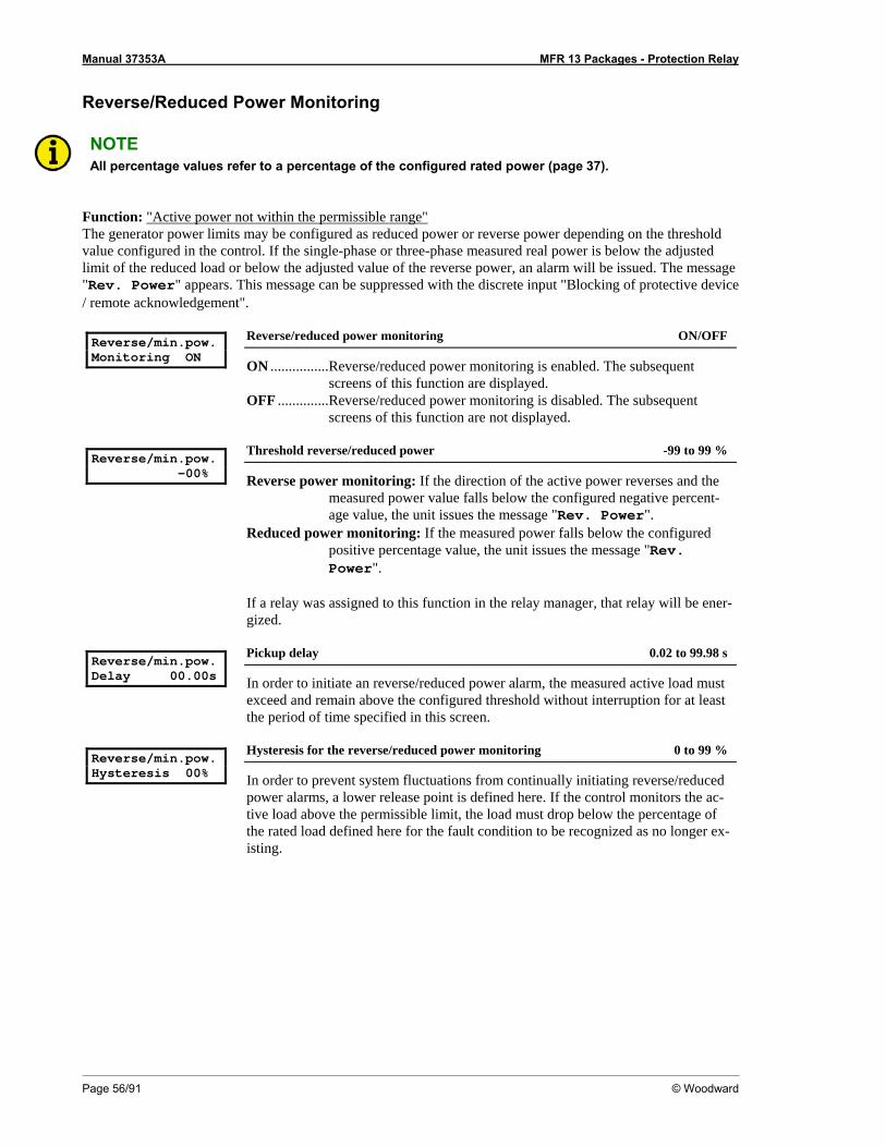
Manual 37353A MFR 13 Packages - Protection Relay
Page 56/91 © Woodward
Reverse/Reduced Power Monitoring
NOTE All percentage values refer to a percentage of the configured rated power (page 37).
Function: "Active power not within the permissible range" The generator power limits may be configured as reduced power or reverse power depending on the threshold value configured in the control. If the single-phase or three-phase measured real power is below the adjusted limit of the reduced load or below the adjusted value of the reverse power, an alarm will be issued. The message "Rev. Power" appears. This message can be suppressed with the discrete input "Blocking of protective device / remote acknowledgement". Reverse/min.pow. Monitoring ON
Reverse/reduced power monitoring ON/OFF
ON ................Reverse/reduced power monitoring is enabled. The subsequent screens of this function are displayed.
OFF ..............Reverse/reduced power monitoring is disabled. The subsequent screens of this function are not displayed.
Reverse/min.pow. -00%
Threshold reverse/reduced power -99 to 99 %
Reverse power monitoring: If the direction of the active power reverses and the measured power value falls below the configured negative percent-age value, the unit issues the message "Rev. Power".
Reduced power monitoring: If the measured power falls below the configured positive percentage value, the unit issues the message "Rev. Power".
If a relay was assigned to this function in the relay manager, that relay will be ener-gized.
Reverse/min.pow. Delay 00.00s
Pickup delay 0.02 to 99.98 s
In order to initiate an reverse/reduced power alarm, the measured active load must exceed and remain above the configured threshold without interruption for at least the period of time specified in this screen.
Reverse/min.pow. Hysteresis 00%
Hysteresis for the reverse/reduced power monitoring 0 to 99 %
In order to prevent system fluctuations from continually initiating reverse/reduced power alarms, a lower release point is defined here. If the control monitors the ac-tive load above the permissible limit, the load must drop below the percentage of the rated load defined here for the fault condition to be recognized as no longer ex-isting.
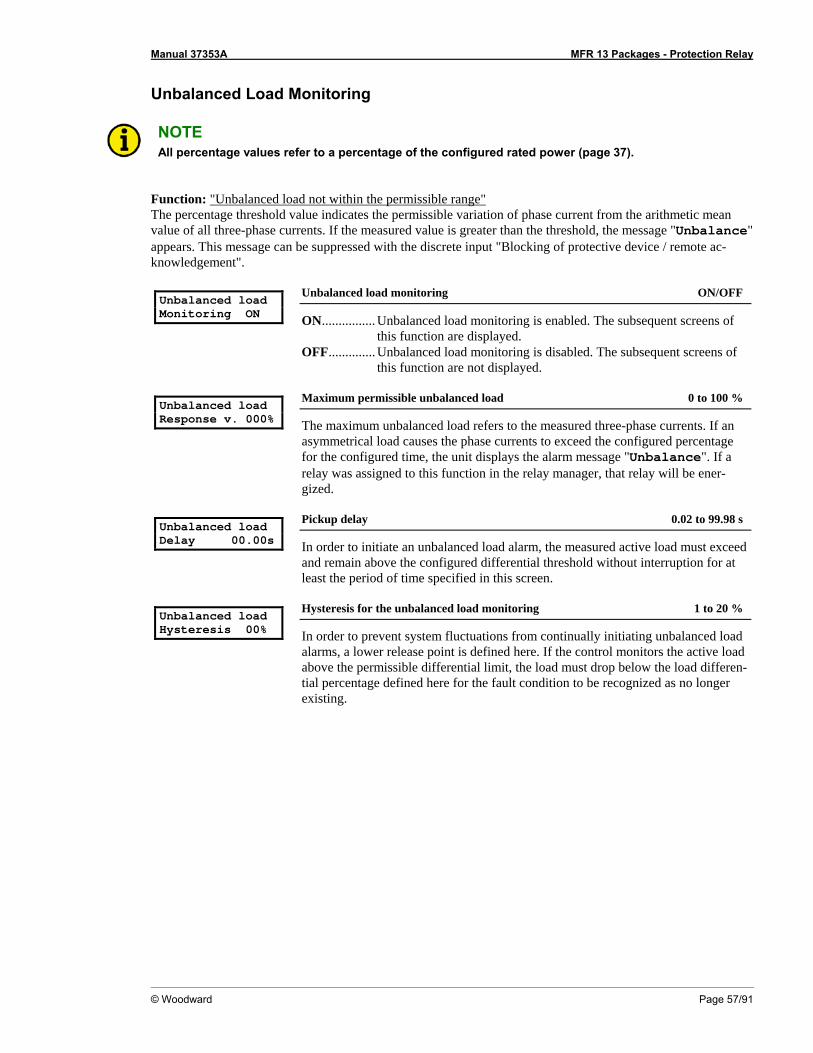
Manual 37353A MFR 13 Packages - Protection Relay
© Woodward Page 57/91
Unbalanced Load Monitoring
NOTE All percentage values refer to a percentage of the configured rated power (page 37).
Function: "Unbalanced load not within the permissible range" The percentage threshold value indicates the permissible variation of phase current from the arithmetic mean value of all three-phase currents. If the measured value is greater than the threshold, the message "Unbalance" appears. This message can be suppressed with the discrete input "Blocking of protective device / remote ac-knowledgement". Unbalanced load Monitoring ON
Unbalanced load monitoring ON/OFF
ON................ Unbalanced load monitoring is enabled. The subsequent screens of this function are displayed.
OFF.............. Unbalanced load monitoring is disabled. The subsequent screens of this function are not displayed.
Unbalanced load Response v. 000%
Maximum permissible unbalanced load 0 to 100 %
The maximum unbalanced load refers to the measured three-phase currents. If an asymmetrical load causes the phase currents to exceed the configured percentage for the configured time, the unit displays the alarm message "Unbalance". If a relay was assigned to this function in the relay manager, that relay will be ener-gized.
Unbalanced load Delay 00.00s
Pickup delay 0.02 to 99.98 s
In order to initiate an unbalanced load alarm, the measured active load must exceed and remain above the configured differential threshold without interruption for at least the period of time specified in this screen.
Unbalanced load Hysteresis 00%
Hysteresis for the unbalanced load monitoring 1 to 20 %
In order to prevent system fluctuations from continually initiating unbalanced load alarms, a lower release point is defined here. If the control monitors the active load above the permissible differential limit, the load must drop below the load differen-tial percentage defined here for the fault condition to be recognized as no longer existing.
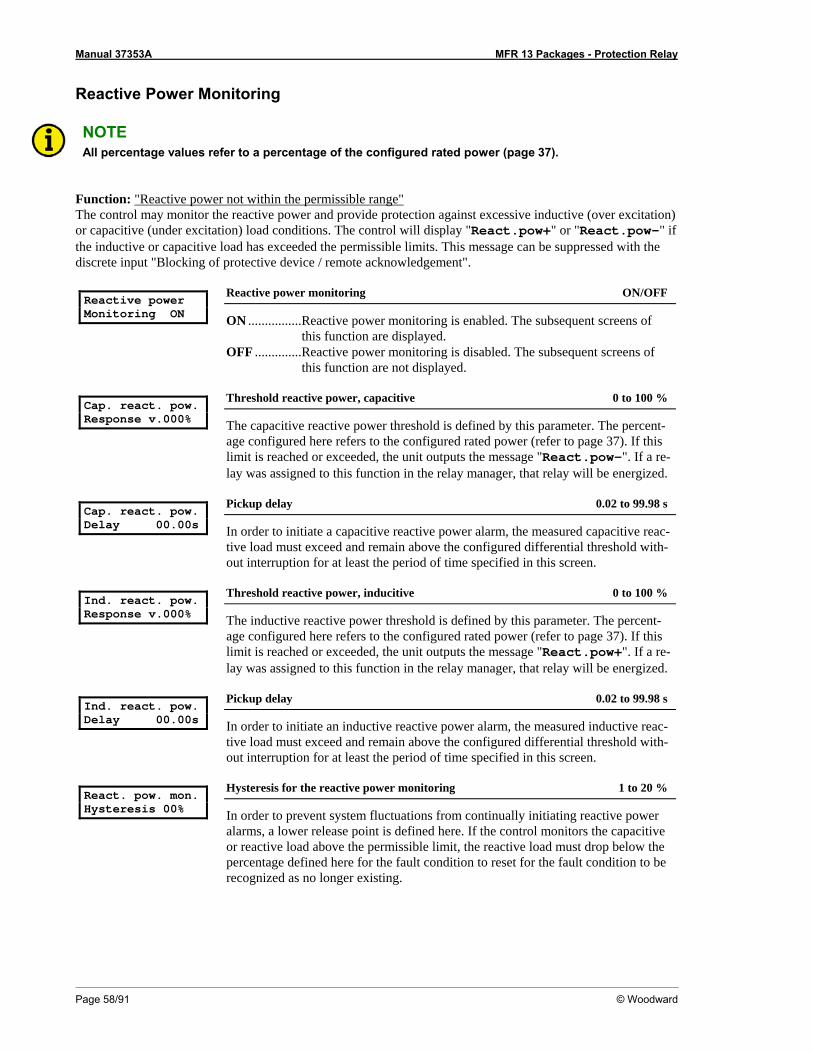
Manual 37353A MFR 13 Packages - Protection Relay
Page 58/91 © Woodward
Reactive Power Monitoring
NOTE All percentage values refer to a percentage of the configured rated power (page 37).
Function: "Reactive power not within the permissible range" The control may monitor the reactive power and provide protection against excessive inductive (over excitation) or capacitive (under excitation) load conditions. The control will display "React.pow+" or "React.pow-" if the inductive or capacitive load has exceeded the permissible limits. This message can be suppressed with the discrete input "Blocking of protective device / remote acknowledgement". Reactive power Monitoring ON
Reactive power monitoring ON/OFF
ON ................Reactive power monitoring is enabled. The subsequent screens of this function are displayed.
OFF ..............Reactive power monitoring is disabled. The subsequent screens of this function are not displayed.
Cap. react. pow. Response v.000%
Threshold reactive power, capacitive 0 to 100 %
The capacitive reactive power threshold is defined by this parameter. The percent-age configured here refers to the configured rated power (refer to page 37). If this limit is reached or exceeded, the unit outputs the message "React.pow-". If a re-lay was assigned to this function in the relay manager, that relay will be energized.
Cap. react. pow. Delay 00.00s
Pickup delay 0.02 to 99.98 s
In order to initiate a capacitive reactive power alarm, the measured capacitive reac-tive load must exceed and remain above the configured differential threshold with-out interruption for at least the period of time specified in this screen.
Ind. react. pow. Response v.000%
Threshold reactive power, inducitive 0 to 100 %
The inductive reactive power threshold is defined by this parameter. The percent-age configured here refers to the configured rated power (refer to page 37). If this limit is reached or exceeded, the unit outputs the message "React.pow+". If a re-lay was assigned to this function in the relay manager, that relay will be energized.
Ind. react. pow. Delay 00.00s
Pickup delay 0.02 to 99.98 s
In order to initiate an inductive reactive power alarm, the measured inductive reac-tive load must exceed and remain above the configured differential threshold with-out interruption for at least the period of time specified in this screen.
React. pow. mon. Hysteresis 00%
Hysteresis for the reactive power monitoring 1 to 20 %
In order to prevent system fluctuations from continually initiating reactive power alarms, a lower release point is defined here. If the control monitors the capacitive or reactive load above the permissible limit, the reactive load must drop below the percentage defined here for the fault condition to reset for the fault condition to be recognized as no longer existing.
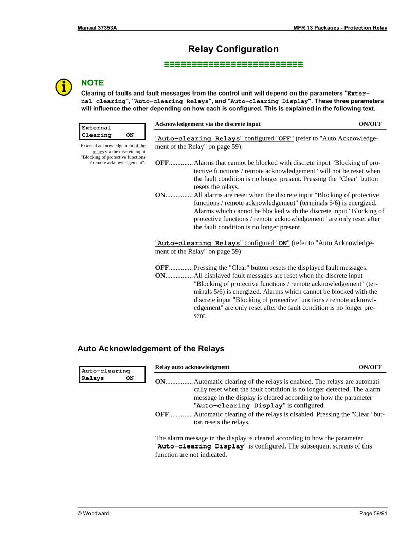
Manual 37353A MFR 13 Packages - Protection Relay
© Woodward Page 59/91
Relay Configuration ≡≡≡≡≡≡≡≡≡≡≡≡≡≡≡≡≡≡≡≡≡≡≡≡≡
NOTE Clearing of faults and fault messages from the control unit will depend on the parameters "Exter-nal clearing", "Auto-clearing Relays", and "Auto-clearing Display". These three parameters will influence the other depending on how each is configured. This is explained in the following text.
External Clearing ON
External acknowledgement of the relays via the discrete input
"Blocking of protective functions / remote acknowledgement".
Acknowledgement via the discrete input ON/OFF
"Auto-clearing Relays" configured "OFF" (refer to "Auto Acknowledge-ment of the Relay" on page 59): OFF.............. Alarms that cannot be blocked with discrete input "Blocking of pro-
tective functions / remote acknowledgement" will not be reset when the fault condition is no longer present. Pressing the "Clear" button resets the relays.
ON................ All alarms are reset when the discrete input "Blocking of protective functions / remote acknowledgement" (terminals 5/6) is energized. Alarms which cannot be blocked with the discrete input "Blocking of protective functions / remote acknowledgement" are only reset after the fault condition is no longer present.
"Auto-clearing Relays" configured "ON" (refer to "Auto Acknowledge-ment of the Relay" on page 59): OFF.............. Pressing the "Clear" button resets the displayed fault messages. ON................ All displayed fault messages are reset when the discrete input
"Blocking of protective functions / remote acknowledgement" (ter-minals 5/6) is energized. Alarms which cannot be blocked with the discrete input "Blocking of protective functions / remote acknowl-edgement" are only reset after the fault condition is no longer pre-sent.
Auto Acknowledgement of the Relays Auto-clearing Relays ON
Relay auto acknowledgment ON/OFF
ON................ Automatic clearing of the relays is enabled. The relays are automati-cally reset when the fault condition is no longer detected. The alarm message in the display is cleared according to how the parameter "Auto-clearing Display" is configured.
OFF.............. Automatic clearing of the relays is disabled. Pressing the "Clear" but-ton resets the relays.
The alarm message in the display is cleared according to how the parameter "Auto-clearing Display" is configured. The subsequent screens of this function are not indicated.
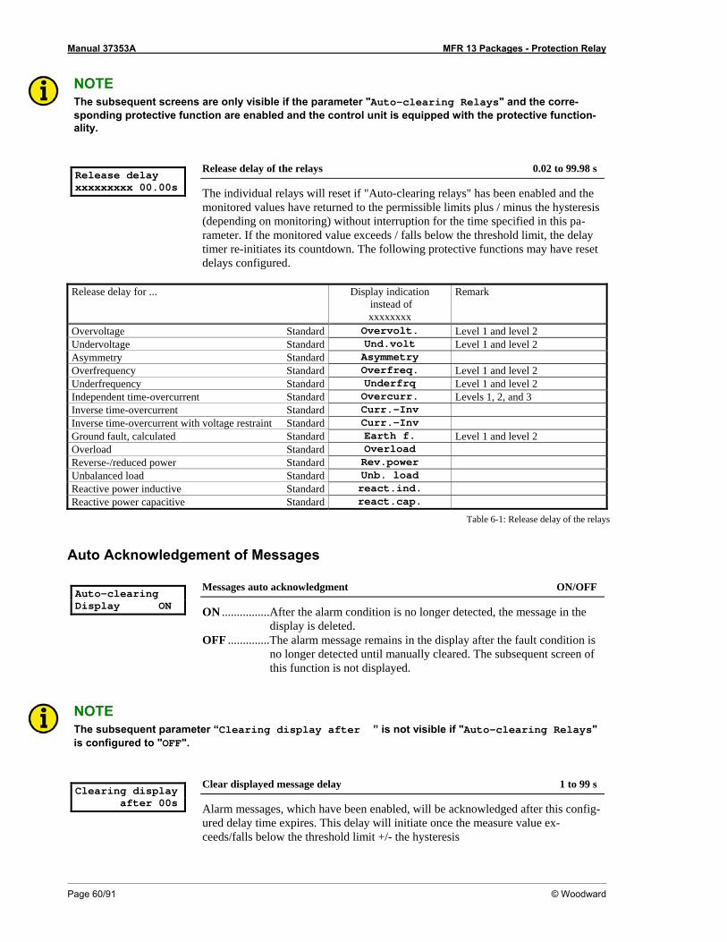
Manual 37353A MFR 13 Packages - Protection Relay
Page 60/91 © Woodward
NOTE The subsequent screens are only visible if the parameter "Auto-clearing Relays" and the corre-sponding protective function are enabled and the control unit is equipped with the protective function-ality.
Release delay xxxxxxxxx 00.00s
Release delay of the relays 0.02 to 99.98 s
The individual relays will reset if "Auto-clearing relays" has been enabled and the monitored values have returned to the permissible limits plus / minus the hysteresis (depending on monitoring) without interruption for the time specified in this pa-rameter. If the monitored value exceeds / falls below the threshold limit, the delay timer re-initiates its countdown. The following protective functions may have reset delays configured.
Release delay for ... Display indication
instead of xxxxxxxx
Remark
Overvoltage Standard Overvolt. Level 1 and level 2 Undervoltage Standard Und.volt Level 1 and level 2 Asymmetry Standard Asymmetry Overfrequency Standard Overfreq. Level 1 and level 2 Underfrequency Standard Underfrq Level 1 and level 2 Independent time-overcurrent Standard Overcurr. Levels 1, 2, and 3 Inverse time-overcurrent Standard Curr.-Inv Inverse time-overcurrent with voltage restraint Standard Curr.-Inv Ground fault, calculated Standard Earth f. Level 1 and level 2 Overload Standard Overload Reverse-/reduced power Standard Rev.power Unbalanced load Standard Unb. load Reactive power inductive Standard react.ind. Reactive power capacitive Standard react.cap.
Table 6-1: Release delay of the relays
Auto Acknowledgement of Messages Auto-clearing Display ON
Messages auto acknowledgment ON/OFF
ON ................After the alarm condition is no longer detected, the message in the display is deleted.
OFF ..............The alarm message remains in the display after the fault condition is no longer detected until manually cleared. The subsequent screen of this function is not displayed.
NOTE The subsequent parameter “Clearing display after ” is not visible if "Auto-clearing Relays" is configured to "OFF".
Clearing display after 00s
Clear displayed message delay 1 to 99 s
Alarm messages, which have been enabled, will be acknowledged after this config-ured delay time expires. This delay will initiate once the measure value ex-ceeds/falls below the threshold limit +/- the hysteresis

Manual 37353A MFR 13 Packages - Protection Relay
© Woodward Page 61/91
Changing the Relay Assignment Change relay- allocation? YES
Change relay assignment? YES/NO
This parameter permits the user to change how the relay outputs are configured. Refer to the list of parameters. YES.............. The relay assignments can be configured and the user may define the
relay functionality and assignments. The subsequent screens are dis-played.
NO................ The relays are configured with the factory default settings. The sub-sequent screens are not displayed.
NOTE All relay outputs are configured the same. The following is an example showing relays 1 through 3. Depending on the model purchased, the unit may have up to 7 configurable relays. The Packages GPX / GPX-I / GPY-I / GPY-I-N / K08 enable to use 4 additional relays.
Example: Relay 1 to 3 Funct. relay 123 (R=releases) RRR
Function of the relays 1, 2, and 3 E/R
The individual relays may be configured as either E=Energizes (Normally Open contacts) or R=Releases (Normally Closed contacts). E ................... The relay is configured as normally open (N.O.) contacts. The relay
will energize only if the assigned monitoring function has tripped. R................... The relay is configured as normally closed (N.C.) contacts. The relay
is always energized and will only de-energize (release) if the as-signed monitoring function has tripped.
NOTE Relay 1 is configured as R (release/N.C.) and cannot be modified.
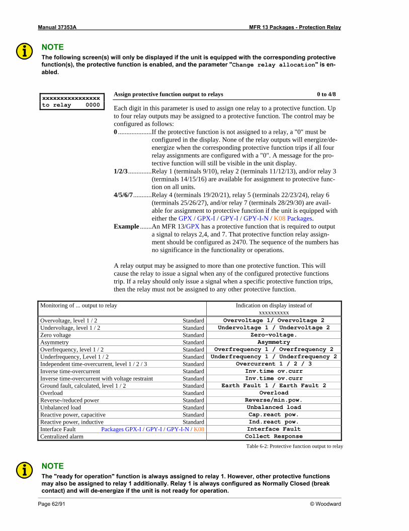
Manual 37353A MFR 13 Packages - Protection Relay
Page 62/91 © Woodward
NOTE The following screen(s) will only be displayed if the unit is equipped with the corresponding protective function(s), the protective function is enabled, and the parameter "Change relay allocation" is en-abled.
xxxxxxxxxxxxxxxx to relay 0000
Assign protective function output to relays 0 to 4/8
Each digit in this parameter is used to assign one relay to a protective function. Up to four relay outputs may be assigned to a protective function. The control may be configured as follows: 0 ....................If the protective function is not assigned to a relay, a "0" must be
configured in the display. None of the relay outputs will energize/de-energize when the corresponding protective function trips if all four relay assignments are configured with a "0". A message for the pro-tective function will still be visible in the unit display.
1/2/3 ..............Relay 1 (terminals 9/10), relay 2 (terminals 11/12/13), and/or relay 3 (terminals 14/15/16) are available for assignment to protective func-tion on all units.
4/5/6/7...........Relay 4 (terminals 19/20/21), relay 5 (terminals 22/23/24), relay 6 (terminals 25/26/27), and/or relay 7 (terminals 28/29/30) are avail-able for assignment to protective function if the unit is equipped with either the GPX / GPX-I / GPY-I / GPY-I-N / K08 Packages.
Example .......An MFR 13/GPX has a protective function that is required to output a signal to relays 2,4, and 7. That protective function relay assign-ment should be configured as 2470. The sequence of the numbers has no significance in the functionality or operations.
A relay output may be assigned to more than one protective function. This will cause the relay to issue a signal when any of the configured protective functions trip. If a relay should only issue a signal when a specific protective function trips, then the relay must not be assigned to any other protective function.
Monitoring of ... output to relay Indication on display instead of
xxxxxxxxxx Overvoltage, level 1 / 2 Standard Overvoltage 1/ Overvoltage 2 Undervoltage, level 1 / 2 Standard Undervoltage 1 / Undervoltage 2 Zero voltage Standard Zero-voltage. Asymmetry Standard Asymmetry Overfrequency, level 1 / 2 Standard Overfrequency 1 / Overfrequency 2 Underfrequency, Level 1 / 2 Standard Underfrequency 1 / Underfrequency 2 Independent time-overcurrent, level 1 / 2 / 3 Standard Overcurrent 1 / 2 / 3 Inverse time-overcurrent Standard Inv.time ov.curr Inverse time-overcurrent with voltage restraint Standard Inv.time ov.curr Ground fault, calculated, level 1 / 2 Standard Earth Fault 1 / Earth Fault 2 Overload Standard Overload Reverse-/reduced power Standard Reverse/min.pow. Unbalanced load Standard Unbalanced load Reactive power, capacitive Standard Cap.react pow. Reactive power, inductive Standard Ind.react pow. Interface Fault Packages GPX-I / GPY-I / GPY-I-N / K08 Interface Fault Centralized alarm Collect Response
Table 6-2: Protective function output to relay
NOTE The "ready for operation" function is always assigned to relay 1. However, other protective functions may also be assigned to relay 1 additionally. Relay 1 is always configured as Normally Closed (break contact) and will de-energize if the unit is not ready for operation.
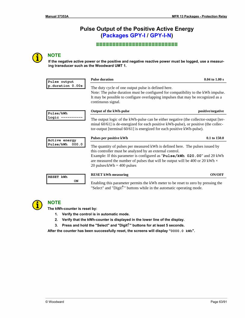
Manual 37353A MFR 13 Packages - Protection Relay
© Woodward Page 63/91
Pulse Output of the Positive Active Energy (Packages GPY-I / GPY-I-N)
≡≡≡≡≡≡≡≡≡≡≡≡≡≡≡≡≡≡≡≡≡≡≡≡≡
NOTE If the negative active power or the positive and negative reactive power must be logged, use a measur-ing transducer such as the Woodward UMT 1.
Pulse output p.duration 0.00s
Pulse duration 0.04 to 1.00 s
The duty cycle of one output pulse is defined here. Note: The pulse duration must be configured for compatibility to the kWh impulse. It may be possible to configure overlapping impulses that may be recognized as a continuous signal.
Pulse/kWh Logic ----------
Output of the kWh-pulse positive/negative
The output logic of the kWh-pulse can be either negative (the collector-output [ter-minal 60/61] is de-energized for each positive kWh-pulse), or positive (the collec-tor-output [terminal 60/61] is energized for each positive kWh-pulse).
Active energy Pulse/kWh 000.0
Pulses per positive kWh 0.1 to 150.0
The quantity of pulses per measured kWh is defined here. The pulses issued by this controller must be analyzed by an external control. Example: If this parameter is configured as "Pulse/kWh 020.00" and 20 kWh are measured the number of pulses that will be output will be 400 or 20 kWh × 20 pulses/kWh = 400 pulses
RESET kWh ON
RESET kWh measuring ON/OFF
Enabling this parameter permits the kWh meter to be reset to zero by pressing the "Select" and "Digit↑" buttons while in the automatic operating mode.
NOTE The kWh-counter is reset by:
1. Verify the control is in automatic mode. 2. Verify that the kWh-counter is displayed in the lower line of the display. 3. Press and hold the "Select" and "Digit↑" buttons for at least 5 seconds.
After the counter has been successfully reset, the screens will display “0000.0 kWh".

Manual 37353A MFR 13 Packages - Protection Relay
Page 64/91 © Woodward
Analog Outputs (Packages GPY-I / GPY-I-N) ≡≡≡≡≡≡≡≡≡≡≡≡≡≡≡≡≡≡≡≡≡≡≡≡≡
It is possible to configure a linear measuring range for each analog output and assign it to a specific measured value (refer to table 6-3). The -20/0/4 to 20 mA analog outputs may be configured as a -20 to 20 mA, 0 to 20 mA, or 4 to 20 mA output. The user may define the upper and lower limits of the analog input measuring range. Text may be assigned to the input as well. Value Lower and upper setting value 0 mA, 4 mA, -20 mA 20 mA Vol 1 0 to 65,000 V Vol 2 0 to 65,000 V Vol 3 0 to 65,000 V Vol ph-N AV 0 to 65,000 V Vol ph-N max 0 to 65,000 V Vol ph-N min 0 to 65,000 V Vol 1-2 0 to 65,000 V Vol 2-3 0 to 65,000 V Vol 3-1 0 to 65,000 V Vol ph-ph AV 0 to 65,000 V Vol ph-ph max 0 to 65,000 V Vol ph-ph min 0 to 65,000 V Frequency 40.00 to 80.00 Hz Current L1 0 to 9,999 A Current L2 0 to 9,999 A Current L3 0 to 9,999 A Current AV 0 to 9,999 A Current max 0 to 9,999 A Current min 0 to 9,999 A Direct. Cur 1 -9,999 to 9,999 A Direct. Cur 2 -9,999 to 9,999 A Direct. Cur 3 -9,999 to 9,999 A Dir. Current AV -9,999 to 9,999 A Dir. Current max -9,999 to 9,999 A Dir. Current min -9,999 to 9,999 A Active power -32,000 to 32,000 kW Reactive power -32,000 to 32,000 kvar Apparent power 0 to 32,000 kVA cosphi i0.01 to 1.00 to c0.01
1.... The sign of the current values is defined by the polarity of the active component. Table 6-3: Analog outputs, table of values

Manual 37353A MFR 13 Packages - Protection Relay
© Woodward Page 65/91
Example: analog output 2 (-20/0/4 to 20 mA: terminals 52/53) Output of the wire-to-wire voltage L12:
20 mA-output
Analog output 2 0 .. 20 mA
Output range of the analog output 2 (20mA) -20..+20mA / 0..20mA / 4..20mA / OFF
The only variable that may be changed for this parameter is the lower value for this analog output. The upper limit is always +20 mA.
-20..20mA .... -20 mA is the configured low limit for the analog output. 0..20mA ....... 0 mA is the configured low limit for the analog output. 4..20mA ....... 4 mA is the configured low limit for the analog output. OFF.............. The analog output is not enabled. The subsequent screens of this
function are not displayed.
Analog output 2 ----------------
Output value of the analog output 2 see Table 6-3
The parameter that is to be assigned to the output is selected here (refer to Table 6-3).
Analog output 0mA = 00000V
Scaling of the lower output value see Table 6-3
Defines the lower limit of the output. Analog output 20mA = 00000V
Scaling of the upper output value see Table 6-3
Defines the upper limit of the output.
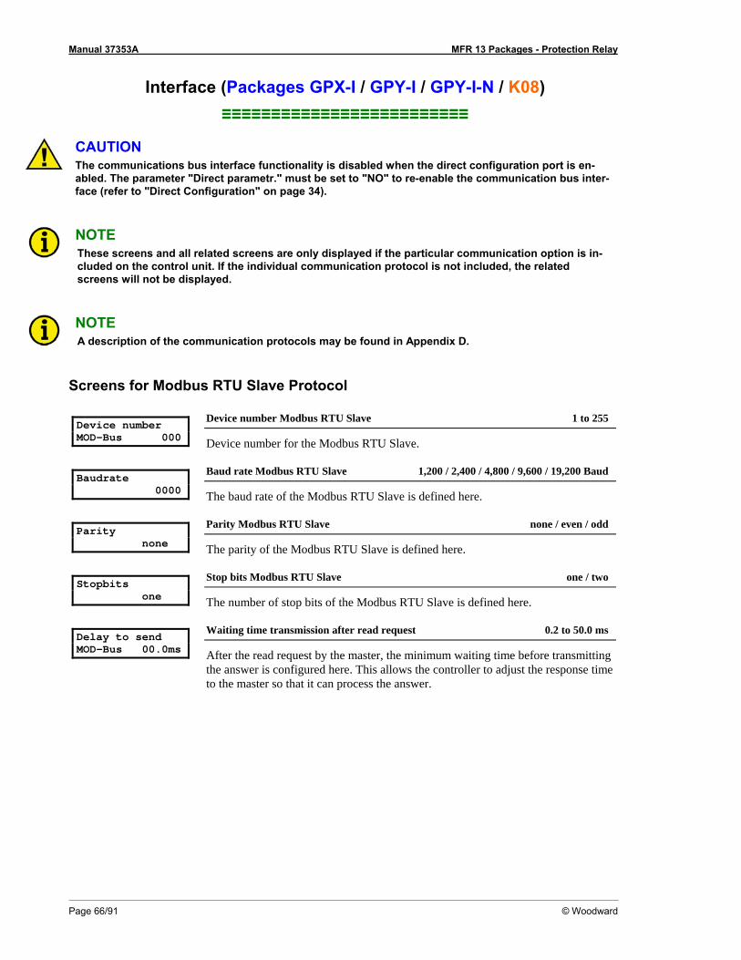
Manual 37353A MFR 13 Packages - Protection Relay
Page 66/91 © Woodward
Interface (Packages GPX-I / GPY-I / GPY-I-N / K08) ≡≡≡≡≡≡≡≡≡≡≡≡≡≡≡≡≡≡≡≡≡≡≡≡≡
CAUTION The communications bus interface functionality is disabled when the direct configuration port is en-abled. The parameter "Direct parametr." must be set to "NO" to re-enable the communication bus inter-face (refer to "Direct Configuration" on page 34).
NOTE These screens and all related screens are only displayed if the particular communication option is in-cluded on the control unit. If the individual communication protocol is not included, the related screens will not be displayed.
NOTE A description of the communication protocols may be found in Appendix D.
Screens for Modbus RTU Slave Protocol Device number MOD-Bus 000
Device number Modbus RTU Slave 1 to 255
Device number for the Modbus RTU Slave. Baudrate 0000
Baud rate Modbus RTU Slave 1,200 / 2,400 / 4,800 / 9,600 / 19,200 Baud
The baud rate of the Modbus RTU Slave is defined here. Parity none
Parity Modbus RTU Slave none / even / odd
The parity of the Modbus RTU Slave is defined here. Stopbits one
Stop bits Modbus RTU Slave one / two
The number of stop bits of the Modbus RTU Slave is defined here. Delay to send MOD-Bus 00.0ms
Waiting time transmission after read request 0.2 to 50.0 ms
After the read request by the master, the minimum waiting time before transmitting the answer is configured here. This allows the controller to adjust the response time to the master so that it can process the answer.
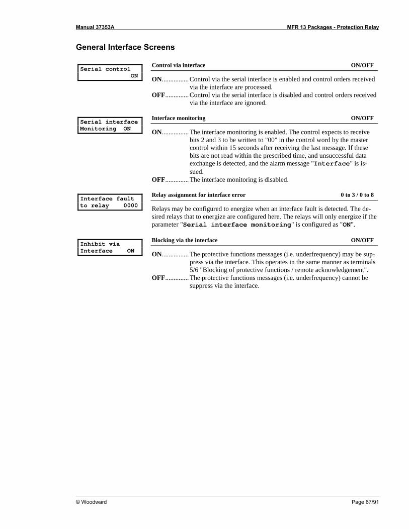
Manual 37353A MFR 13 Packages - Protection Relay
© Woodward Page 67/91
General Interface Screens Serial control ON
Control via interface ON/OFF
ON................ Control via the serial interface is enabled and control orders received via the interface are processed.
OFF.............. Control via the serial interface is disabled and control orders received via the interface are ignored.
Serial interface Monitoring ON
Interface monitoring ON/OFF
ON................ The interface monitoring is enabled. The control expects to receive bits 2 and 3 to be written to "00" in the control word by the master control within 15 seconds after receiving the last message. If these bits are not read within the prescribed time, and unsuccessful data exchange is detected, and the alarm message "Interface" is is-sued.
OFF.............. The interface monitoring is disabled. Interface fault to relay 0000
Relay assignment for interface error 0 to 3 / 0 to 8
Relays may be configured to energize when an interface fault is detected. The de-sired relays that to energize are configured here. The relays will only energize if the parameter "Serial interface monitoring" is configured as "ON".
Inhibit via Interface ON
Blocking via the interface ON/OFF
ON................ The protective functions messages (i.e. underfrequency) may be sup-press via the interface. This operates in the same manner as terminals 5/6 "Blocking of protective functions / remote acknowledgement".
OFF.............. The protective functions messages (i.e. underfrequency) cannot be suppress via the interface.
Manual 37353A MFR 13 Packages - Protection Relay
Page 68/91 © Woodward
Chapter 7. Commissioning
DANGER - HIGH VOLTAGE When commissioning the control, please observe all safety rules that apply to the handling of live equipment. Ensure that you know how to provide first aid in the event of an uncontrolled release of en-ergy and that you know where the first aid kit and the nearest telephone are. Never touch any live com-ponents of the system or on the back of the system:
L I F E T H R E A T E N I N G
CAUTION Only a qualified technician may commission unit. The "EMERGENCY-STOP" function must be opera-tional prior to commissioning of the system, and must not depend on the unit for its operation.
CAUTION Prior to commissioning ensure that all measuring devices are connected in correct phase sequence. The connect command for the unit circuit breaker must be disconnected at the unit circuit breaker. The field rotation must be monitored for proper rotation. Any absence of or incorrect connection of voltage measuring devices or other signals may lead to malfunctions and damage the unit, the engine, and/or components connected to the unit!
Procedure 1. After wiring the unit and ensuring all voltage-measuring devices are phased correctly, apply the control
system voltage (i.e. 24 Vdc). The "Operation" LED will illuminate. 2. By simultaneously pressing the two push buttons "Digit↑" and "Cursor→", the configuration mode is ac-
cessed. After entering the access code number, the unit may be configured according to the application requirements (see the chapter regarding the parameters).
The MFR 1 will not issue a "Connect" signal while it is in configuration mode. 3. After applying the measured variables, the unit will display the measured values. These values should be
confirmed with a calibrated measuring instrument. 4. After the unit has been configured for the application, the configuration mode is exited by simultaneously
pressing the "Digit↑" and "Cursor→" buttons. 5. Check all protection functions and the relay outputs.
Check all control outputs as well as the setting and behavior of the controller outputs (frequency & volt-age)
Manual 37353A MFR 13 Packages - Protection Relay
© Woodward Page 69/91
6. Check the synchronization (Packages GPX / GPX-I / GPY-I / GPY-I-N / K08):
a.) Interrupt the "Connect" signal for the power circuit breaker. b.) The mains voltage (synchronization voltage) must be within the permissible limits. c.) In the moment a connection command is output, the differential voltage between the corresponding
conductors must be equal to zero. This check must be carried out for all three phases, in order to check the correctness of the rotating field.
d.) After a successful check, the "Connect" signal can be connected again. 7. Check the dead bus start function
Prior to checking the dead bus start function, the output of the "Connect" signal must be interrupted. 8. If steps 1 through 7 have been carried out successfully, parallel operations may be commenced. It is rec-
ommended to start with a constant power/baseload operation (approx. 25 % of the generator rated power) initially. While this operation is being carried out, the displayed measured values must be verified. Test the GCB shutdown. Check the real power controller and if necessary the power factor controller for proper operation. Enter various set point values and verify proper operation.
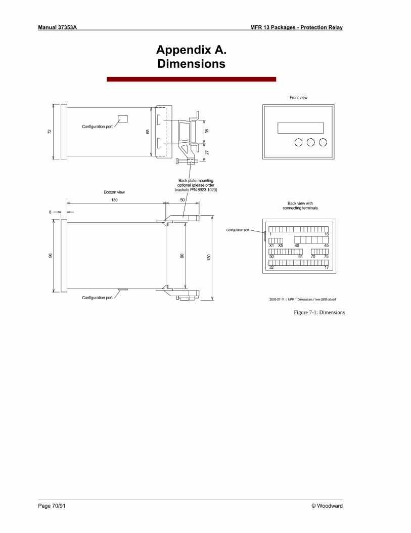
Manual 37353A MFR 13 Packages - Protection Relay
Page 70/91 © Woodward
Appendix A. Dimensions
2005-07-11 | MFR 1 Dimensions r1ww-2805-ab.skf
50130
96
8
90
130
72 65
2735
Back view withconnecting terminals
Bottom view
Back plate mountingoptional (please order
brackets P/N 8923-1023)
Front view
Configuration port
Configuration port
6150
40
1
70 75
45
16
32 17
X5X1
Configuration port
Figure 7-1: Dimensions
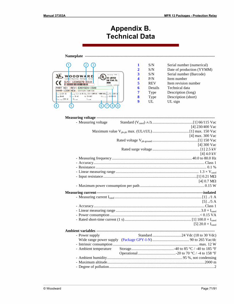
Manual 37353A MFR 13 Packages - Protection Relay
© Woodward Page 71/91
Appendix B. Technical Data
Nameplate -----------------------------------------------------------------------------------------------------
1 S/N Serial number (numerical) 2 S/N Date of production (YYMM) 3 S/N Serial number (Barcode) 4 P/N Item number 5 REV Item revision number 6 Details Technical data 7 Type Description (long) 8 Type Description (short) 9 UL UL sign
Measuring voltage -------------------------------------------------------------------------------------------- - Measuring voltage Standard (Vrated) /Δ ..........................................[1] 66/115 Vac [4] 230/400 Vac Maximum value Vph-ph max. (UL/cUL) ...................................... [1] max. 150 Vac [4] max. 300 Vac Rated voltage Vph-ground ...............................................[1] 150 Vac [4] 300 Vac Rated surge voltage ................................................. [1] 2.5 kV [4] 4.0 kV - Measuring frequency ................................................................................... 40.0 to 80.0 Hz - Accuracy................................................................................................................... Class 1 - Resistance ................................................................................................................... 0.1 % - Linear measuring range ...................................................................................... 1.3 × Vrated - Input resistance.................................................................................................[1] 0.21 MΩ
[4] 0.7 MΩ - Maximum power consumption per path ...................................................................0.15 W
Measuring current-----------------------------------------------------------------------------------isolated - Measuring current Irated .......................................................................................... [1] ../1 A
[5] ../5 A - Accuracy................................................................................................................... Class 1 - Linear measuring range ........................................................................................ 3.0 × Irated - Power consumption .............................................................................................< 0.15 VA - Rated short-time current (1 s) ..................................................................... [1] 100.0 × Irated
[5] 20.0 × Irated
Ambient variables -------------------------------------------------------------------------------------------- - Power supply Standard ..............................24 Vdc (18 to 30 Vdc) Wide range power supply (Package GPY-I-N) ...................................... 90 to 265 Vac/dc - Intrinsic consumption ......................................................................................... max. 12 W - Ambient temperature Storage............................................-40 to 85 °C / -40 to 185 °F Operational .......................................-20 to 70 °C / -4 to 158 °F - Ambient humidity.............................................................................. 95 %, not condensing - Maximum altitude.....................................................................................................2000 m - Degree of pollution.............................................................................................................2
Manual 37353A MFR 13 Packages - Protection Relay
Page 72/91 © Woodward
Discrete inputs----------------------------------------------------------------------------------------isolated - Input range (VCont, discrete input) ..............................................Rated voltage 18 to 250 Vac/dc - Input resistance ............................................................................................. approx. 68 kΩ
Relay outputs ----------------------------------------------------------------------------------potential free - Contact material .......................................................................................................AgCdO - General purpose (GP) (VCont, relay output) AC...................................2.00 Aac@250 Vac DC.................................... 2.00 Adc@24 Vdc
0.36 Adc@125 Vdc 0.18 Adc@250 Vdc
- Pilot duty (PD) (VCont, relay output) AC.................................................................. DC.................................... 1.00 Adc@24 Vdc
0.22 Adc@125 Vdc 0.10 Adc@250 Vdc
Analog outputs ---------------------------------------------------------------------------------------isolated - At rated value.............................................................................................. freely scaleable - Insulation voltage.................................................................................................1,500 Vdc - Resolution PWM........................................................................................................ 12 Bit - -20/0/4 to 20 mA output....................................................................Maximum load 500 Ω
Pulse output----------------------------------------------------------------------------------------------------- - Type ........................................................................................................... transistor output - Rated gate voltage.....................................................................................................24 Vdc - Maximum gate voltage..............................................................................................32 Vdc - Minimum gate current...........................................................................................10 mA dc - Maximum gate current ......................................................................... 30 mA dc (0.5 Vdc)
Interface ----------------------------------------------------------------------------------------------isolated - Insulation voltage................................................... dependent on model: 500 to 3,000 Vdc - Version.................................................................................................................... variable
Housing ---------------------------------------------------------------------------------------------------------- - Type ...........................................................................................APRANORM DIN 43 700 - Dimensions (W × H × D)........................................................................96 × 72 × 130 mm - Front cutout (W × H) .................................................................. 91 [+1.0] × 67 [+0.7] mm - Wiring ...........Screw-type terminals depending on connector 1.5 mm², 2.5 mm², or 4 mm² - Recommended tightening torque ................ [1.5 mm² / 2.5 mm²] 0.5 Nm, [4 mm²] 0.6 Nm
use 60/75 °C copper wire only use class 1 wire only or equivalent
- Weight............................................................................................................ approx. 800 g
Protection ------------------------------------------------------------------------------------------------------- - Protection system ....................................................IP42 from front with correct mounting
IP54 from front with gasket (gasket: P/N 8923-1036) IP21 from back
- Front foil .................................................................................................. insulating surface - EMC test (CE)............................................... tested according to applicable EN guidelines - Listings........................................................ CE marking; UL listing for ordinary locations
UL/cUL listed, Ordinary Locations, File No.: E231544 (Package GPY-I-N not UL/cUL listed)
- Marine-Approval.............................................................................................................GL

Manual 37353A MFR 13 Packages - Protection Relay
© Woodward Page 73/91
Appendix C. Measured Quantities and Accuracy
Measuring value Display/range Accuracy Note Frequency fL1, fL2, fL3 40.0 to 80.0 Hz 0.05 Hz Voltage VL1, VL2, VL3, VL12, VL23, VL31 0 to 520 V/0 to 65 kV 1 % Accuracy depending on the
configured transformer ratio Current IL1, IL2, IL3 0 to 9,999 A 1 % Accuracy depending on the
configured transformer ratio Real power Total real actual power -32.0 to 32.0 MW 2 % Accuracy depending on the
configured transformer ratio Re-active power Actual value in L1, L2, L3 -32.0 to 32.0 Mvar 2 % Accuracy depending on the
configured transformer ratio Apparent power Actual value in L1, L2, L3 0 to 45.0 MVA 2 % Accuracy depending on the
configured transformer ratio Power factor (cos ϕ) Actual value (cos ϕL1) c0.00 to 1.00 to i0.00 1.5 ° -
Reference conditions: The data apply to the following reference conditions: • Input voltage = sinusoidal rated voltage • Input current = sinusoidal rated current • Frequency = rated frequency ± 2 % • Power supply = rated voltage ± 2 % • Power factor cos ϕ = 1 • Ambient temperature 23 °C ± 2 K • Warm-up period = 20 minutes.

Manual 37353A MFR 13 Packages - Protection Relay
Page 74/91 © Woodward
Appendix D. Interface Telegram
Communication Interface Addresses ≡≡≡≡≡≡≡≡≡≡≡≡≡≡≡≡≡≡≡≡≡≡≡≡≡
Transmission Message
Number Content (words) Unit Remark 3964 Modbus CAN bus Profibus
00 01 1 (02, 03) MUX=1, 1 0 Telegram header "302" Telegram type 02 03 2 (04, 05) MUX=1, 2 1 Voltage L12 V 04 05 3 (06, 07) MUX=1, 3 2 Voltage L23 V 06 07 4 (08, 09) MUX=2, 1 3 Voltage L31 V 08 09 5 (10, 11) MUX=2, 2 4 Voltage L1N V 10 11 6 (12, 13) MUX=2, 3 5 Voltage L2N V 12 13 7 (14, 15) MUX=3, 1 6 Voltage L3N V 14 15 8 (16, 17) MUX=3, 2 7 Frequency L12 Hz × 100 16 17 9 (18, 19) MUX=3, 3 8 Current L1 A 18 19 10 (20, 21) MUX=4, 1 9 Current L2 A 20 21 11 (22, 23) MUX=4, 2 10 Current L3 A 22 23 12 (24, 25) MUX=4, 3 11 Power factor (cosphi) dim.less × 100 24 25 13 (26, 27) MUX=5, 1 12 Real power kW 26 27 14 (28, 29) MUX=5, 2 13 Reactive power kvar 28 29 15 (30, 31) MUX=5, 3 14 Busbar voltage L12 V 30 31 16 (32, 33) MUX=6, 1 15 Busbar voltage L12 Hz × 100
32 17 (34) MUX=6, 2 16 dim.less VGN 33 17 (35) MUX=6, 2 16
Exponent dim.less IGN
34 18 (36) MUX=6, 3 17 dim.less PGN/QGN 35 18 (37) MUX=6, 3 17
Exponent dim.less VSS
36 37 19 (38, 39) MUX=7, 1 18 kWh High Word 38 39 20 (40, 41) MUX=7, 2 19
Generator real energy Low Word
40 41 21 (42, 43) MUX=7, 3 20 Internal alarms 1 Bit 15 = 1 \ Bit 14 = 0 / Overfrequency level 2
Bit 13 = 1 \ Bit 12 = 0 / Underfrequency level 2
Bit 11 = 1 \ Bit 10 = 0 / Overvoltage level 2
Bit 9 = 1 \ Bit 8 = 0 / Overvoltage level 2
Bit 7 = 1 \ Bit 6 = 0 / Unbalanced load
Bit 5 = 1 \ Bit 4 = 0 / Overcurrent level 1
Note (example bit 15/14):
Bit 3 = 1 \ Bit 2 = 0 / Overload
0/1 = alarm not triggered 1/0 = alarm triggered
Bit 1 = 1 \ Bit 0 = 0 / Reverse/reduced power
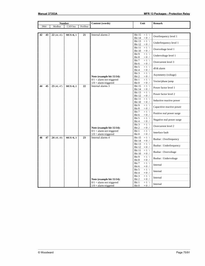
Manual 37353A MFR 13 Packages - Protection Relay
© Woodward Page 75/91
Number Content (words) Unit Remark
3964 Modbus CAN bus Profibus
42 43 22 (44, 45) MUX=8, 1 21 Internal alarms 2 Bit 15 = 1 \ Bit 14 = 0 / Overfrequency level 1
Bit 13 = 1 \ Bit 12 = 0 / Underfrequency level 1
Bit 11 = 1 \ Bit 10 = 0 / Overvoltage level 1
Bit 9 = 1 \ Bit 8 = 0 / Undervoltage level 1
Bit 7 = 1 \ Bit 6 = 0 / Overcurrent level 3
Bit 5 = 1 \ Bit 4 = 0 / df/dt alarm
Note (example bit 15/14):
Bit 3 = 1 \ Bit 2 = 0 / Asymmetry (voltage)
0/1 = alarm not triggered 1/0 = alarm triggered
Bit 1 = 1 \ Bit 0 = 0 / Vector/phase jump
44 45 23 (46, 47) MUX=8, 2 22 Internal alarms 3 Bit 15 = 1 \ Bit 14 = 0 / Power factor level 1
Bit 13 = 1 \ Bit 12 = 0 / Power factor level 2
Bit 11 = 1 \ Bit 10 = 0 / Inductive reactive power
Bit 9 = 1 \ Bit 8 = 0 / Capacitive reactive power
Bit 7 = 1 \ Bit 6 = 0 / Positive real power surge
Bit 5 = 1 \ Bit 4 = 0 / Negative real power surge
Note (example bit 15/14):
Bit 3 = 1 \ Bit 2 = 0 / Overcurrent level 2
0/1 = alarm not triggered 1/0 = alarm triggered
Bit 1 = 1 \ Bit 0 = 0 / Interface fault
46 47 24 (48, 49) MUX=8, 3 23 Internal alarms 4 Bit 15 = 1 \ Bit 14 = 0 / Busbar : Overfrequency
Bit 13 = 1 \ Bit 12 = 0 / Busbar : Underfrequency
Bit 11 = 1 \ Bit 10 = 0 / Busbar : Overvoltage
Bit 9 = 1 \ Bit 8 = 0 / Busbar : Undervoltage
Bit 7 = 1 \ Bit 6 = 0 / Internal
Bit 5 = 1 \ Bit 4 = 0 / Internal
Note (example bit 15/14):
Bit 3 = 1 \ Bit 2 = 0 / Internal
0/1 = alarm not triggered 1/0 = alarm triggered
Bit 1 = 1 \ Bit 0 = 0 / Internal
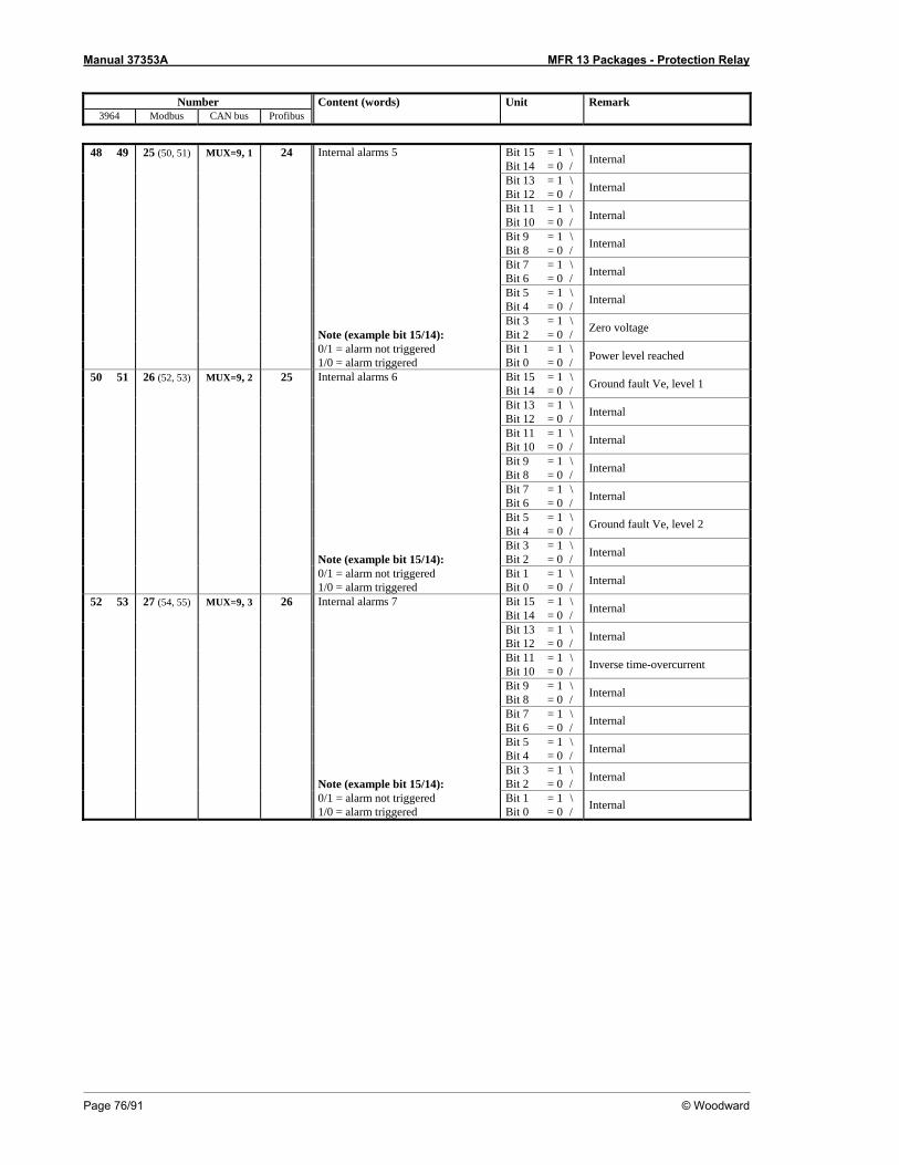
Manual 37353A MFR 13 Packages - Protection Relay
Page 76/91 © Woodward
Number Content (words) Unit Remark
3964 Modbus CAN bus Profibus
48 49 25 (50, 51) MUX=9, 1 24 Internal alarms 5 Bit 15 = 1 \ Bit 14 = 0 / Internal
Bit 13 = 1 \ Bit 12 = 0 / Internal
Bit 11 = 1 \ Bit 10 = 0 / Internal
Bit 9 = 1 \ Bit 8 = 0 / Internal
Bit 7 = 1 \ Bit 6 = 0 / Internal
Bit 5 = 1 \ Bit 4 = 0 / Internal
Note (example bit 15/14):
Bit 3 = 1 \ Bit 2 = 0 / Zero voltage
0/1 = alarm not triggered 1/0 = alarm triggered
Bit 1 = 1 \ Bit 0 = 0 / Power level reached
50 51 26 (52, 53) MUX=9, 2 25 Internal alarms 6 Bit 15 = 1 \ Bit 14 = 0 / Ground fault Ve, level 1
Bit 13 = 1 \ Bit 12 = 0 / Internal
Bit 11 = 1 \ Bit 10 = 0 / Internal
Bit 9 = 1 \ Bit 8 = 0 / Internal
Bit 7 = 1 \ Bit 6 = 0 / Internal
Bit 5 = 1 \ Bit 4 = 0 / Ground fault Ve, level 2
Note (example bit 15/14):
Bit 3 = 1 \ Bit 2 = 0 / Internal
0/1 = alarm not triggered 1/0 = alarm triggered
Bit 1 = 1 \ Bit 0 = 0 / Internal
52 53 27 (54, 55) MUX=9, 3 26 Internal alarms 7 Bit 15 = 1 \ Bit 14 = 0 / Internal
Bit 13 = 1 \ Bit 12 = 0 / Internal
Bit 11 = 1 \ Bit 10 = 0 / Inverse time-overcurrent
Bit 9 = 1 \ Bit 8 = 0 / Internal
Bit 7 = 1 \ Bit 6 = 0 / Internal
Bit 5 = 1 \ Bit 4 = 0 / Internal
Note (example bit 15/14):
Bit 3 = 1 \ Bit 2 = 0 / Internal
0/1 = alarm not triggered 1/0 = alarm triggered
Bit 1 = 1 \ Bit 0 = 0 / Internal
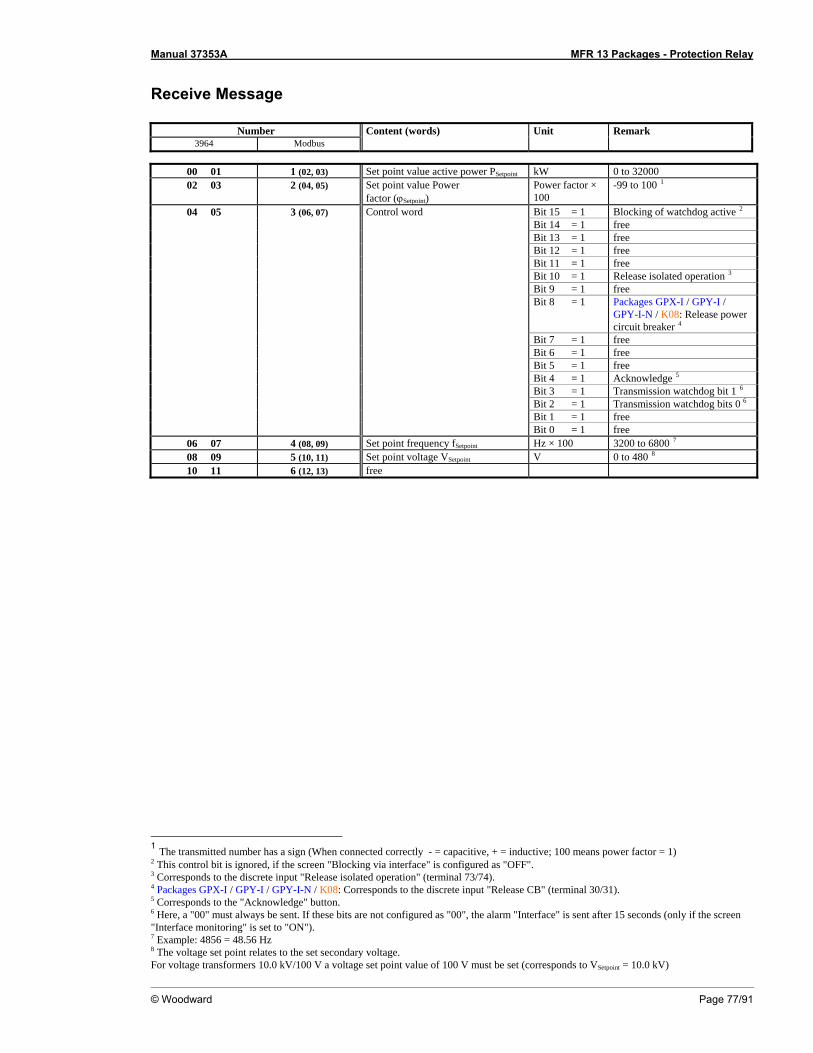
Manual 37353A MFR 13 Packages - Protection Relay
© Woodward Page 77/91
Receive Message
Number Content (words) Unit Remark 3964 Modbus
00 01 1 (02, 03) Set point value active power PSetpoint kW 0 to 32000 02 03 2 (04, 05) Set point value Power
factor (ϕSetpoint) Power factor × 100
-99 to 100 1
04 05 3 (06, 07) Control word Bit 15 = 1 Blocking of watchdog active 2 Bit 14 = 1 free Bit 13 = 1 free Bit 12 = 1 free Bit 11 = 1 free Bit 10 = 1 Release isolated operation 3 Bit 9 = 1 free Bit 8 = 1 Packages GPX-I / GPY-I /
GPY-I-N / K08: Release power circuit breaker 4
Bit 7 = 1 free Bit 6 = 1 free Bit 5 = 1 free Bit 4 = 1 Acknowledge 5 Bit 3 = 1 Transmission watchdog bit 1 6 Bit 2 = 1 Transmission watchdog bits 0 6 Bit 1 = 1 free Bit 0 = 1 free
06 07 4 (08, 09) Set point frequency fSetpoint Hz × 100 3200 to 6800 7 08 09 5 (10, 11) Set point voltage VSetpoint V 0 to 480 8 10 11 6 (12, 13) free
1 The transmitted number has a sign (When connected correctly - = capacitive, + = inductive; 100 means power factor = 1) 2 This control bit is ignored, if the screen "Blocking via interface" is configured as "OFF". 3 Corresponds to the discrete input "Release isolated operation" (terminal 73/74). 4 Packages GPX-I / GPY-I / GPY-I-N / K08: Corresponds to the discrete input "Release CB" (terminal 30/31). 5 Corresponds to the "Acknowledge" button. 6 Here, a "00" must always be sent. If these bits are not configured as "00", the alarm "Interface" is sent after 15 seconds (only if the screen "Interface monitoring" is set to "ON"). 7 Example: 4856 = 48.56 Hz 8 The voltage set point relates to the set secondary voltage. For voltage transformers 10.0 kV/100 V a voltage set point value of 100 V must be set (corresponds to VSetpoint = 10.0 kV)

Manual 37353A MFR 13 Packages - Protection Relay
Page 78/91 © Woodward
Description of the Data Format ≡≡≡≡≡≡≡≡≡≡≡≡≡≡≡≡≡≡≡≡≡≡≡≡≡
NOTE Certain addresses have two parts, the measured value and the exponent multiplier!
Voltage and current 0 to 9999 without sign measured in [V, A], no exponent Real power 0 to 9999 with sign measured in [W]; data format: two's complement positive = positive power negative = negative power (reverse power) Reactive power 0 to 9999 with sign measured in [var]; data format: two's complement positive = inductive negative = capacitive Frequency measured in [Hz × 100] Real energy 32 Bit measured in [kWh]; data format: two's complement positive = exported real energy negative = imported real energy Power factor (cos phi) -99 to +100 measured in [cos phi × 100] positive = inductive/leading, generator over-excited negative = capacitive/lagging, generator under-excited
Scalable range (0 to 20 mA)eg. c0.70 to 1.00 to i0.70
Power factor cosphi = 1.00
c 0.00
Capacitive(negative)
Lower distanceeg. 0030
Higher distanceeg. 0030
i 0.00
Inductive(positive)
Figure 7-2: Interface, power factor scaling
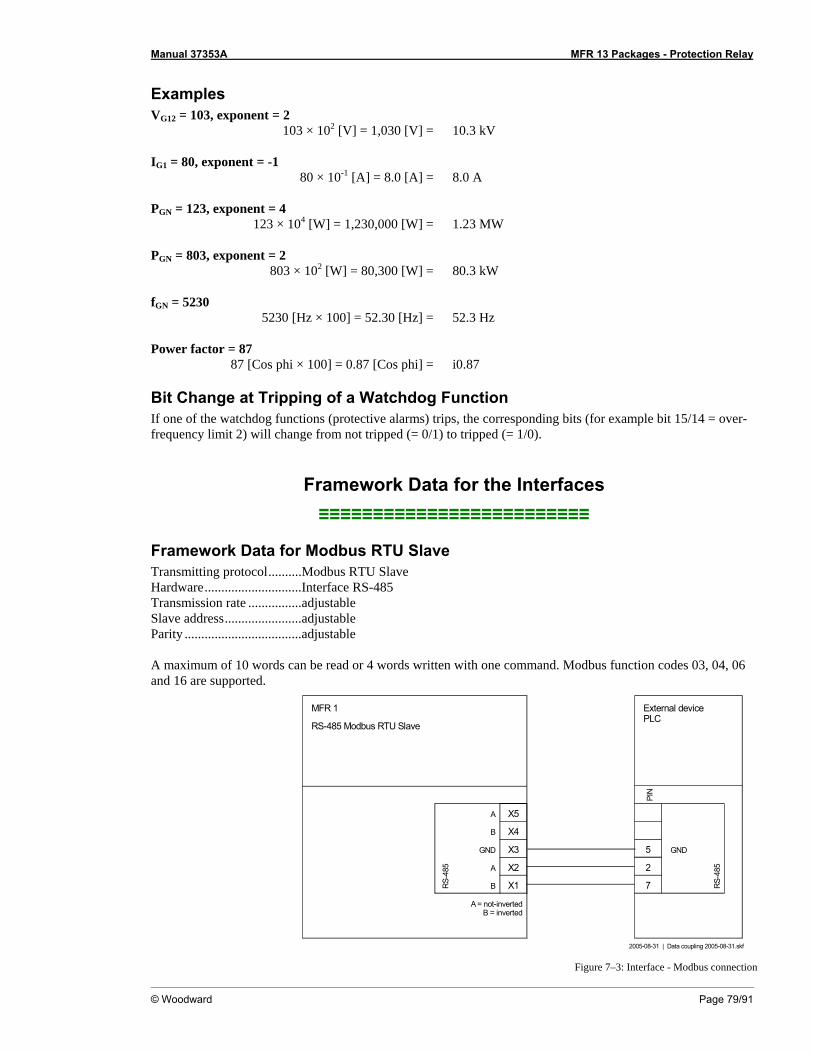
Manual 37353A MFR 13 Packages - Protection Relay
© Woodward Page 79/91
Examples VG12 = 103, exponent = 2 103 × 102 [V] = 1,030 [V] = 10.3 kV IG1 = 80, exponent = -1 80 × 10-1 [A] = 8.0 [A] = 8.0 A PGN = 123, exponent = 4 123 × 104 [W] = 1,230,000 [W] = 1.23 MW PGN = 803, exponent = 2 803 × 102 [W] = 80,300 [W] = 80.3 kW fGN = 5230 5230 [Hz × 100] = 52.30 [Hz] = 52.3 Hz Power factor = 87 87 [Cos phi × 100] = 0.87 [Cos phi] = i0.87
Bit Change at Tripping of a Watchdog Function If one of the watchdog functions (protective alarms) trips, the corresponding bits (for example bit 15/14 = over-frequency limit 2) will change from not tripped (= 0/1) to tripped (= 1/0).
Framework Data for the Interfaces ≡≡≡≡≡≡≡≡≡≡≡≡≡≡≡≡≡≡≡≡≡≡≡≡≡
Framework Data for Modbus RTU Slave Transmitting protocol..........Modbus RTU Slave Hardware.............................Interface RS-485 Transmission rate ................adjustable Slave address.......................adjustable Parity ...................................adjustable A maximum of 10 words can be read or 4 words written with one command. Modbus function codes 03, 04, 06 and 16 are supported.
MFR 1
2005-08-31 | Data coupling 2005-08-31.skf
PIN
5 GND
RS-4
85External devicePLC
A = not-invertedB = inverted
GND
RS-4
85
X3
X1
X2
A
B X4
X5
7
2
RS-485 Modbus RTU Slave
A
B
Figure 7–3: Interface - Modbus connection

Manual 37353A MFR 13 Packages - Protection Relay
Page 80/91 © Woodward
Appendix E. List of Parameters
Product number P/N _____________________________ Rev ______________________________ Version MFR 13 ______________________________________________________________ Project _____________________________________________________________________ Serial number S/N _______________ Date _____________________________
Pkg. Parameter Setting range 100/400 V version Default setting Customer setting
BASIC DATA
Software version - - SPRACHE/LANGUAGE German/English English G E G E Enter code 0000 to 9999 - Password Protection ON/OFF ON 1 0 1 0 Define level 1 code 0000 to 9999 0001 Define level 2 code 0000 to 9999 0002 Direct parametr. YES/NO NO Y N Y N
MEASUREMENT Volt.-Measuring Phase to phase / Phase-neutral Phase-neutral pn pp pn pp
GP / K08 Volt.transformer secondary 50 to 125/50 to 480 V 100/400 V GP / K08 Volt.transformer primary 00.100 to 65.000 kV 00.400 kV
GPX GPX-I GPY-I
GPY-I-N
Volt.transformer sec.(GN) 50 to 125/50 to 480 V 100/400 V
.. Volt.transformer prim(GN) 00.100 to 65.000 kV 00.400 kV
.. Volt.transformer sec.(MN) 50 to 125/50 to 480 V 100/400 V GPX
GPX-I GPY-I
GPY-I-N Volt.transformer prim(MN) 00.100 to 65.000 kV 00.400 kV
Current transf. 1 to 9,999/{x} A 1,000/{x} A GPX
GPX-I GPY-I
GPY-I-N K08
Rated voltage 5 to 125/10 to 480 V 100/400 V
GPX GPX-I GPY-I
GPY-I-N K08
Rated frequency 40.0 to 70.0 Hz 50.0 Hz
Rated current 1 to 9,999 A 1,000 A Rated power 5 to 32,000 kW 500 kW Power measuring one-phase/three-phase three-phase s t s t
CONTROL FUNCTIONS GPX
GPX-I GPY-I
GPY-I-N K08
Synchronizing ON/OFF ON 1 0 1 0
.. Synchronization df max 0.02 to 0.49 Hz 0.18 Hz
.. Synchronization df min 0.00 to -0.49 Hz -0.10 Hz
.. Synchronization dV max 0.1 to 15.0 % 6.0 %
.. Synchronization Max phase < 1 to 60° 2°
.. Synchronization Time pulse> 50 to 250 ms 200 ms GPX
GPX-I GPY-I
GPY-I-N K08
Gen.circ.breaker Pick-up t. 40 to 300 ms 80 ms
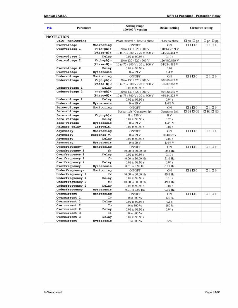
Manual 37353A MFR 13 Packages - Protection Relay
© Woodward Page 81/91
Pkg. Parameter Setting range 100/400 V version Default setting Customer setting
PROTECTION
Volt. Monitoring Phase-neutral / Phase to phase Phase to phase pn pp pn pp Overvoltage Monitoring ON/OFF ON 1 0 1 0 Overvoltage 1 V(ph-ph)> 20 to 130 / 520 / 900 V 110/440/769 V (Phase-N)> 10 to 75 / 300 V / 20 to 900 V 64/254/444 V Overvoltage 1 Delay 0.02 to 99.98 s 0.10 s Overvoltage 2 V(ph-ph)> 20 to 130 / 520 / 900 V 120/480/839 V (Phase-N)> 10 to 75 / 300 V / 20 to 900 V 64/254/485 V Overvoltage 2 Delay 0.02 to 99.98 s 0.04 Overvoltage Hysteresis 0 to 99 V 1/4 V Undervoltage Monitoring ON/OFF ON 1 0 1 0 Undervoltage 1 V(ph-ph)< 20 to 130 / 520 / 900 V 90/360/629 V (Phase-N)< 10 to 75 / 300 V / 20 to 900 V 51/207/363 V Undervoltage 1 Delay 0.02 to 99.98 s 0.10 s Undervoltage 2 V(ph-ph)< 20 to 130 / 520 / 900 V 80/320/559 V (Phase-N)< 10 to 75 / 300 V / 20 to 900 V 46/184/323 V Undervoltage 2 Delay 0.02 to 99.98 s 0.04 s Undervoltage Hysteresis 0 to 99 V 1/4/8 V Zero-voltage Monitoring ON/OFF ON 1 0 1 0 Zero-voltage Busbar 1ph / Generator 3ph Generator 3ph B1 G3 B1 G3 Zero-voltage V(ph-ph)< 8 to 150 V 8 V Zero-voltage Delay 0.02 to 99.98 s 0.25 s Zero-voltage Hysteresis 0 to 99 V 1/4/8 V Release delay Zerovolt. 0.02 to 99.98 s 0.04 s Asymmetry- Monitoring ON/OFF ON 1 0 1 0 Asymmetry Response v. 0 to 99 V 10/40/69 V Asymmetry Delay 0.02 to 99.98 s 2.00 s Asymmetry Hysteresis 0 to 99 V 1/4/6 V Overfrequency- Monitoring ON/OFF ON 1 0 1 0 Overfrequency 1 f> 40.00 to 80.00 Hz 50.2 Hz Overfrequency 1 Delay 0,02 to 99.98 s 0.10 s Overfrequency 2 f> 40.00 to 80.00 Hz 51.0 Hz Overfrequency 2 Delay 0.02 to 99.98 s 0.04 s Overfrequency Hysteresis 0.01 to 9.99 Hz 0.05 Hz Underfrequency- Monitoring ON/OFF ON 1 0 1 0 Underfrequency 1 f< 40.00 to 80.00 Hz 49.8 Hz Underfrequency 1 Delay 0.02 to 99.98 s 0.10 s Underfrequency 2 f< 40.00 to 80.00 Hz 49.0 Hz Underfrequency 2 Delay 0.02 to 99.98 s 0.04 s Underfrequency Hysteresis 0.01 to 9.99 Hz 0.05 Hz Overcurrent Monitoring ON/OFF ON 1 0 1 0 Overcurrent 1 I> 0 to 300 % 120 % Overcurrent 1 Delay 0.02 to 99.98 s 0.1 s Overcurrent 2 I> 0 to 300 % 160 % Overcurrent 2 Delay 0.02 to 99.98 s 0.04 s Overcurrent 3 I> 0 to 300 % Overcurrent 3 Delay 0.02 to 99.98 s Overcurrent Hysteresis 1 to 300 % 5 %
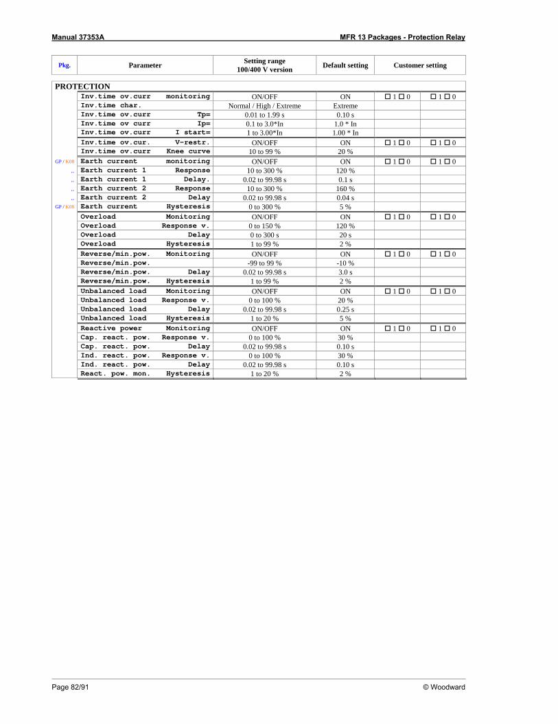
Manual 37353A MFR 13 Packages - Protection Relay
Page 82/91 © Woodward
Pkg. Parameter Setting range 100/400 V version Default setting Customer setting
PROTECTION
Inv.time ov.curr monitoring ON/OFF ON 1 0 1 0 Inv.time char. Normal / High / Extreme Extreme Inv.time ov.curr Tp= 0.01 to 1.99 s 0.10 s Inv.time ov curr Ip= 0.1 to 3.0*In 1.0 * In Inv.time ov.curr I start= 1 to 3.00*In 1.00 * In Inv.time ov.cur. V-restr. ON/OFF ON 1 0 1 0 Inv.time ov.curr Knee curve 10 to 99 % 20 %
GP / K08 Earth current monitoring ON/OFF ON 1 0 1 0 .. Earth current 1 Response 10 to 300 % 120 % .. Earth current 1 Delay. 0.02 to 99.98 s 0.1 s .. Earth current 2 Response 10 to 300 % 160 % .. Earth current 2 Delay 0.02 to 99.98 s 0.04 s
GP / K08 Earth current Hysteresis 0 to 300 % 5 % Overload Monitoring ON/OFF ON 1 0 1 0 Overload Response v. 0 to 150 % 120 % Overload Delay 0 to 300 s 20 s Overload Hysteresis 1 to 99 % 2 % Reverse/min.pow. Monitoring ON/OFF ON 1 0 1 0 Reverse/min.pow. -99 to 99 % -10 % Reverse/min.pow. Delay 0.02 to 99.98 s 3.0 s Reverse/min.pow. Hysteresis 1 to 99 % 2 % Unbalanced load Monitoring ON/OFF ON 1 0 1 0 Unbalanced load Response v. 0 to 100 % 20 % Unbalanced load Delay 0.02 to 99.98 s 0.25 s Unbalanced load Hysteresis 1 to 20 % 5 % Reactive power Monitoring ON/OFF ON 1 0 1 0 Cap. react. pow. Response v. 0 to 100 % 30 % Cap. react. pow. Delay 0.02 to 99.98 s 0.10 s Ind. react. pow. Response v. 0 to 100 % 30 % Ind. react. pow. Delay 0.02 to 99.98 s 0.10 s React. pow. mon. Hysteresis 1 to 20 % 2 %

Manual 37353A MFR 13 Packages - Protection Relay
© Woodward Page 83/91
Pkg. Parameter Setting range 100/400 V version Default setting Customer setting
RELAYS
External Clearing ON/OFF OFF 1 0 1 0 Auto-clearing relays ON/OFF OFF 1 0 1 0 Release delay Overvoltage 0.02 to 99.98 s 0.10 s Release delay Undervoltage 0.02 to 99.98 s 0.10 s Release delay Asymmetry 0.02 to 99.98 s 0.10 s Release delay Overfreq. 0.02 to 99.98 s 0.10 s Release delay Underfrq. 0.02 to 99.98 s 0.10 s Release delay Overcurr. 0.02 to 99.98 s 0.20 s
GP / K08 Release delay Earth F. 0.02 to 99.98 s 0.20 s Release delay Overload 0.02 to 99.98 s 0.10 s Release delay Rev.Power 0.02 to 99.98 s 0.10 s Release delay Unb. Load 0.02 to 99.98 s 0.10 s Release delay react.cap. 0.02 to 99.98 s 0.10 s Release delay react.ind. 0.02 to 99.98 s 0.10 s Auto-clearing Display ON/OFF OFF 1 0 1 0 Clearing display after 1 to 99 s 1 s Change relay- allocation YES/NO NO Y N Y N Funct. relay 12 E/R RE Funct. relay 123 E/R REE
GPX GPX-I GPY-I
GPY-I-N K08
Funct. relay 45 E/R EE
GPX GPX-I GPY-I
GPY-I-N K08
Funct. relay 678 E/R EEE
Collect response to relay 0 to 3/7 0002 Overvoltage 1 to relay 0 to 3/7 0002 Overvoltage 2 to relay 0 to 3/7 0002 Undervoltage 1 to relay 0 to 3/7 0002 Undervoltage 2 to relay 0 to 3/7 0002 Zero-voltage to relay 0 to 3/7 0002 Asymmetry to relay 0 to 3/7 0002 Overfrequency 1 to relay 0 to 3/7 0003 Overfrequency 2 to relay 0 to 3/7 0003 Underfrequency 1 to relay 0 to 3/7 0003 Underfrequency 2 to relay 0 to 3/7 0003 Overcurrent1 to relay 0 to 3/7 0002 Overcurrent2 to relay 0 to 3/7 0002 Overcurrent3 to relay 0 to 3/7 0002 Current-Inv. to relay 0 to 3/7 0002
GP / K08 Earth Fault 1 to relay 0 to 3/7 0003 GP / K08 Earth Fault 2 to relay 0 to 3/7 0003
Overload to relay 0 to 3/7 0003 Reverse/min.pow. to relay 0 to 3/7 0003 Unbalanced Load to relay 0 to 3/7 0002 Ind. react.pow. to relay 0 to 3/7 0002 Neg. react.pow. to relay 0 to 3/7 0002
GPX-I GPY-I
GPY-I-N K08
Interface Fault to relay 0 to 3/7 0002
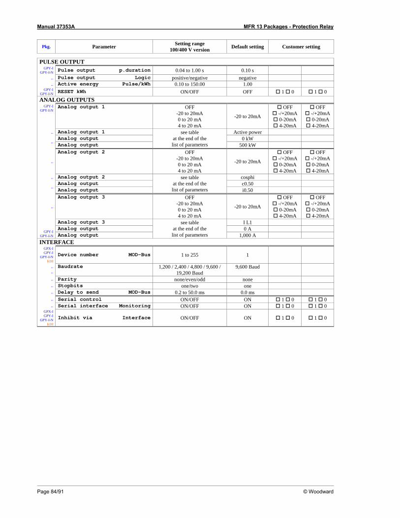
Manual 37353A MFR 13 Packages - Protection Relay
Page 84/91 © Woodward
Pkg. Parameter Setting range 100/400 V version Default setting Customer setting
PULSE OUTPUT
GPY-I GPY-I-N Pulse output p.duration 0.04 to 1.00 s 0.10 s
.. Pulse output Logic positive/negative negative
.. Active energy Pulse/kWh 0.10 to 150.00 1.00 GPY-I
GPY-I-N RESET kWh ON/OFF OFF 1 0 1 0 ANALOG OUTPUTS
GPY-I GPY-I-N
Analog output 1 OFF -20 to 20mA 0 to 20 mA 4 to 20 mA
-20 to 20mA
OFF -/+20mA 0-20mA 4-20mA
OFF -/+20mA 0-20mA 4-20mA
.. Analog output 1 Active power Analog output 0 kW .. Analog output
see table at the end of the list of parameters 500 kW
..
Analog output 2 OFF -20 to 20mA 0 to 20 mA 4 to 20 mA
-20 to 20mA
OFF -/+20mA 0-20mA 4-20mA
OFF -/+20mA 0-20mA 4-20mA
.. Analog output 2 cosphi Analog output c0.50 .. Analog output
see table at the end of the list of parameters i0.50
..
Analog output 3 OFF -20 to 20mA 0 to 20 mA 4 to 20 mA
-20 to 20mA
OFF -/+20mA 0-20mA 4-20mA
OFF -/+20mA 0-20mA 4-20mA
Analog output 3 I L1 Analog output 0 A GPY-I
GPY-I-N Analog output
see table at the end of the list of parameters 1,000 A
INTERFACE GPX-I GPY-I
GPY-I-N K08
Device number MOD-Bus 1 to 255 1
..
.. Baudrate 1,200 / 2,400 / 4,800 / 9,600 /
19,200 Baud 9,600 Baud
.. Parity none/even/odd none
.. Stopbits one/two one
.. Delay to send MOD-Bus 0.2 to 50.0 ms 0.0 ms
.. Serial control ON/OFF ON 1 0 1 0
.. Serial interface Monitoring ON/OFF ON 1 0 1 0 GPX-I GPY-I
GPY-I-N K08
Inhibit via Interface ON/OFF ON 1 0 1 0

Manual 37353A MFR 13 Packages - Protection Relay
© Woodward Page 85/91
Value Lower and upper setting value 0 mA, 4 mA, -20 mA 20 mA Vol 1 0 to 65,000 V Vol 2 0 to 65,000 V Vol 3 0 to 65,000 V Vol ph-N AV 0 to 65,000 V Vol ph-N max 0 to 65,000 V Vol ph-N min 0 to 65,000 V Vol 1-2 0 to 65,000 V Vol 2-3 0 to 65,000 V Vol 3-1 0 to 65,000 V Vol ph-ph AV 0 to 65,000 V Vol ph-ph max 0 to 65,000 V Vol ph-ph min 0 to 65,000 V Frequency 40.00 to 80.00 Hz Current L1 0 to 9,999 A Current L2 0 to 9,999 A Current L3 0 to 9,999 A Current AV 0 to 9,999 A Current max 0 to 9,999 A Current min 0 to 9,999 A Direct. Cur 1 -9,999 to 9,999 A Direct. Cur 2 -9,999 to 9,999 A Direct. Cur 3 -9,999 to 9,999 A Dir. Current AV -9,999 to 9,999 A Dir. Current max -9,999 to 9,999 A Dir. Current min -9,999 to 9,999 A Active power -32,000 to 32,000 kW Reactive power -32,000 to 32,000 kvar Apparent power 0 to 32,000 kVA cosphi i0.01 to 1.00 to c0.01
1.... The sign of the current values is defined by the polarity of the active component. Table 7-1: Analog outputs, table of values
Manual 37353A MFR 13 Packages - Protection Relay
Page 86/91 © Woodward
Appendix F. Service Options
Product Service Options ≡≡≡≡≡≡≡≡≡≡≡≡≡≡≡≡≡≡≡≡≡≡≡≡≡
The following factory options are available for servicing Woodward equipment, based on the standard Wood-ward Product and Service Warranty (5-01-1205) that is in effect at the time the product is purchased from Woodward or the service is performed. If you are experiencing problems with installation or unsatisfactory per-formance of an installed system, the following options are available: • Consult the troubleshooting guide in the manual. • Contact Woodward technical assistance (refer to "How to Contact Woodward" later in this chapter) and dis-
cuss your problem. In most cases, your problem can be resolved over the phone. If not, you can select which course of action you wish to pursue based on the available services listed in this section.
Returning Equipment for Repair ≡≡≡≡≡≡≡≡≡≡≡≡≡≡≡≡≡≡≡≡≡≡≡≡≡
If a control (or any part of an electronic control) is to be returned to Woodward for repair, please contact Wood-ward in advance to obtain a Return Authorization Number. When shipping the unit(s), attach a tag with the fol-lowing information: • name and location where the control is installed; • name and phone number of contact person; • complete Woodward part numbers (P/N) and serial number (S/N); • description of the problem; • instructions describing the desired repair.
CAUTION To prevent damage to electronic components caused by improper handling, read and observe the pre-cautions in Woodward manual 82715, Guide for Handling and Protection of Electronic Controls, Printed Circuit Boards, and Modules.
Manual 37353A MFR 13 Packages - Protection Relay
© Woodward Page 87/91
Packing a Control Use the following materials when returning a complete control: • protective caps on any connectors; • antistatic protective bags on all electronic modules; • packing materials that will not damage the surface of the unit; • at least 100 mm (4 inches) of tightly packed, industry-approved packing material; • a packing carton with double walls; • a strong tape around the outside of the carton for increased strength.
Return Authorization Number RAN When returning equipment to Woodward, please telephone and ask for the Customer Service Department in Stuttgart [+49 (711) 789 54-0]. They will help expedite the processing of your order through our distributors or local service facility. To expedite the repair process, contact Woodward in advance to obtain a Return Authoriza-tion Number, and arrange for issue of a purchase order for the unit(s) to be repaired. No work can be started until a purchase order is received.
NOTE We highly recommend that you make arrangement in advance for return shipments. Contact a Wood-ward customer service representative at +49 (711) 789 54-0 for instructions and for a Return Authoriza-tion Number.
Replacement Parts ≡≡≡≡≡≡≡≡≡≡≡≡≡≡≡≡≡≡≡≡≡≡≡≡≡
When ordering replacement parts for controls, include the following information: • the part numbers P/N (XXXX-XXX) that is on the enclosure nameplate; • the unit serial number S/N, which is also on the nameplate.

Manual 37353A MFR 13 Packages - Protection Relay
Page 88/91 © Woodward
How to Contact Woodward ≡≡≡≡≡≡≡≡≡≡≡≡≡≡≡≡≡≡≡≡≡≡≡≡≡
Please contact following address if you have questions or if you want to send a product for repair: Woodward GmbH Handwerkstrasse 29 70565 Stuttgart - Germany Phone: +49 (711) 789 54-0 (8.00 - 16.30 German time) Fax: +49 (711) 789 54-100 e-mail: [email protected] For assistance outside Germany, call one of the following international Woodward facilities to obtain the address and phone number of the facility nearest your location where you will be able to get information and service. Facility Phone number USA +1 (970) 482 5881 India +91 (129) 409 7100 Brazil +55 (19) 3708 4800 Japan +81 (476) 93 4661 The Netherlands +31 (23) 566 1111 You can also contact the Woodward Customer Service Department or consult our worldwide directory on Woodward’s website (www.woodward.com) for the name of your nearest Woodward distributor or service fa-cility. [For worldwide directory information, go to www.woodward.com/ic/locations.]

Manual 37353A MFR 13 Packages - Protection Relay
© Woodward Page 89/91
Engineering Services ≡≡≡≡≡≡≡≡≡≡≡≡≡≡≡≡≡≡≡≡≡≡≡≡≡
Woodward Industrial Controls Engineering Services offers the following after-sales support for Woodward prod-ucts. For these services, you can contact us by telephone, by e-mail, or through the Woodward website. • Technical support • Product training • Field service during commissioning Technical Support is available through our many worldwide locations, through our authorized distributors, or through GE Global Controls Services, depending on the product. This service can assist you with technical ques-tions or problem solving during normal business hours. Emergency assistance is also available during non-business hours by phoning our toll-free number and stating the urgency of your problem. For technical engineer-ing support, please contact us via our toll-free or local phone numbers, e-mail us, or use our website and refer-ence technical support. Product Training is available on-site from several of our worldwide facilities, at your location, or from GE Global Controls Services, depending on the product. This training, conducted by experienced personnel, will as-sure that you will be able to maintain system reliability and availability. For information concerning training, please contact us via our toll-free or local phone numbers, e-mail us, or use our website and reference customer training. Field Service engineering on-site support is available, depending on the product and location, from our facility in Colorado, or from one of many worldwide Woodward offices or authorized distributors. Field engineers are experienced on both Woodward products as well as on much of the non-Woodward equipment with which our products interface. For field service engineering assistance, please contact us via our toll-free or local phone numbers, e-mail us, or use our website and reference field service.

Manual 37353A MFR 13 Packages - Protection Relay
Page 90/91 © Woodward
Technical Assistance ≡≡≡≡≡≡≡≡≡≡≡≡≡≡≡≡≡≡≡≡≡≡≡≡≡
If you need to telephone for technical assistance, you will need to provide the following information. Please write it down here before phoning: Contact Your company____________________________________________________ Your name_______________________________________________________ Phone number ____________________________________________________ Fax number ______________________________________________________ Control (see name plate) Unit no. and Revision: P/N:____________________ REV: ____________ Unit type MFR 13____________________________________ Serial number S/N _______________________________________ Description of your problem _______________________________________________________________
_______________________________________________________________
_______________________________________________________________
_______________________________________________________________
_______________________________________________________________
_______________________________________________________________
Please be sure you have a list of all parameters available.

We appreciate your comments about the content of our publications. Please send comments to: [email protected]
Please include the manual number from the front cover of this publication.
Woodward GmbH
Handwerkstrasse 29 - 70565 Stuttgart - Germany Phone +49 (711) 789 54-0 • Fax +49 (711) 789 54-100
Homepage
http://www.woodward.com/power
Woodward has company-owned plants, subsidiaries, and branches, as well as authorized distributors and other authorized service and sales facilities throughout the world.
Complete address/phone/fax/e-mail information
for all locations is available on our website (www.woodward.com).
2007/7/Stuttgart


