[email protected]MGF 300 SERIES STRUT MGF TECHNICAL FILE 4.2.1 Issue 4 Description Highly versatile, simple to assemble, medium duty, modular bracing strut system designed primarily to be used as intermediate struts with MGF hydraulic bracing systems. The system can also be used in any plane to prop steel, concrete or masonry structures. Each strut comprises either hydraulic ram or mechanical jack assemblies together with various length strut extension bars. The system can support loads of up to 600kN and span from 1.1m to approx 18.0m and can incorporate a central cruciform bar offering intermediate vertical support to perpendicular struts. Components are heavy and are normally assembled on site prior to being lifted into place and installed within the excavation using either large excavators or cranes. A variety of end bearings are available allowing the struts to be used at a wide range of angles and within any plane. Fabricated from grade S355 300x300 steel box section the extensions are quickly assembled into the required strut lengths using flanged plates c/w bolt, nut and washer assemblies. Final length adjustment is provided by either a double acting hydraulic ram or a mechanical (screw thread adjusted) jack providing up to 745mm of stroke. Once located at the correct line and level the struts are pre-loaded (or tightened) against the faces to be supported using a hydraulic pump on the ram (or by striking the locking collar of the mechanical jack). Pre- loading of the legs ensures the strut cannot slip, takes up any slack or hogging in the system and minimises the extent of potential ground movements. Handling points are provided at regular intervals on each leg to assist assembly / removal. MGF can supply the systems with a full range of suitable handling chains, hydraulic pump installation kits (including bio-degradable shoring fluid and hydraulic hoses) and confined spaces regime equipment. Manufactured and designed in accordance with BS EN 14653:2005 PARTS 1 and 2 Manually operated Shoring Systems for Groundwork Support and BS 5975 (2008) Code of Practice for Temporary Works Procedures and the Permissible Stress Design of Falsework. Product Notes 1. Strut systems are heavy and should only be assembled, installed and removed by competent persons in accordance with a site specific detailed design & installation sequence and MGF installation guidelines. 2. Installation is normally carried out by assembling the complete strut and then lowering into place (subject to crane / excavator capacity). Struts are normally long and unbalanced (due to the weight of ram/jack unit) and great care must be taken in preparing the lift / maintaining lift angle (tag lines strongly recommended). On the ram assembly max pre-load pressure of 100Bar (1500psi) must not be exceeded unless design states otherwise. 3. Additional restraining chains or support brackets are normally provided to the brace at intermediate strut locations to carry the additional strut weight. 4. Ensure struts are fully pre-loaded or tightened, end fixings packed, all hydraulic ram isolation valves are closed prior to releasing strut from lifting chains and commencing works. When assembling on site ensure that all pins and retaining clips are in place and secured and all flange plate bolts are installed and fully tightened / torqued with a minimum two threads visible beyond the nut. Any gaps in bearing plates must be securely packed by using hardwood wedges or grout prior to final pre-loading of the hydraulic rams. 5. Individual components should be visually inspected for damage, excessive deflection, loss of ram pressure or loose locking collars prior to entering the excavation. 6. Safe access/egress, edge protection (for personnel) and barrier protection (for plant) should always be considered. 7. Prior to removal of systems the complete weight of the strut must be independently supported. Once this is accomplished the hydraulic rams (or struts) must be released and retracted to avoid the need for excessive extraction forces. 8. When installing struts at angles great care must be taken to ensure that the angles match the design, all shear stops are in place and all elements are supported/packed and capable of transmitting loads effectively. 9. Extreme care must be taken when handling the mechanical jack as the screw thread is free to move within the outer and can accidently retract or extend. It is therefore recommended that during handling operations the jack is fully extended and the locking collar closed against the outer to prevent any sudden movements.
DescriptionHighly versatile, simple to assemble, medium duty, modular bracing strut system designed primarily to be used as intermediate struts with MGF hydraulic bracing systems. The system can also be used in any plane to prop steel, concrete or masonry structures. Each strut comprises either hydraulic ram or mechanical jack assemblies together with various length strut extension bars. The system can support loads of up to 600kN and span from 1.1m to approx 18.0m and can incorporate a central cruciform bar offering intermediate vertical support to perpendicular struts. Components are heavy and are normally assembled on site prior to being lifted into place and installed within the excavation using either large excavators or cranes. A variety of end bearings are available allowing the struts to be used at a wide range of angles and within any plane.
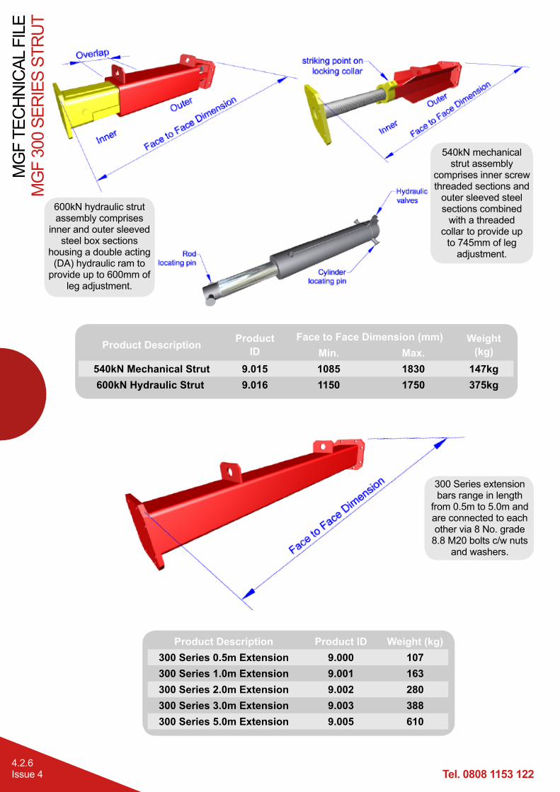
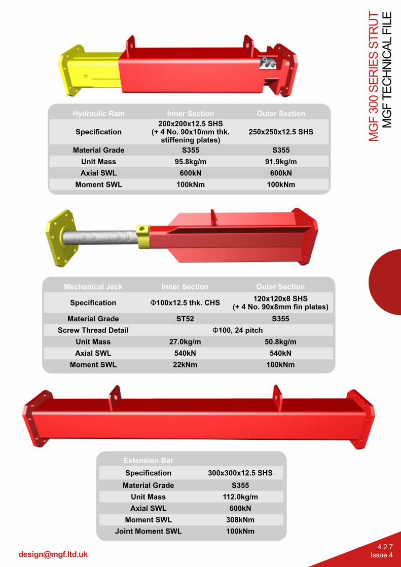
Fabricated from grade S355 300x300 steel box section the extensions are quickly assembled into the required strut lengths using flanged plates c/w bolt, nut and washer assemblies. Final length adjustment is provided by either a double acting hydraulic ram or a mechanical (screw thread adjusted) jack providing up to 745mm of stroke. Once located at the correct line and level the struts are pre-loaded (or tightened) against the faces to be supported using a hydraulic pump on the ram (or by striking the locking collar of the mechanical jack). Pre-loading of the legs ensures the strut cannot slip, takes up any slack or hogging in the system and minimises the extent of potential ground movements. Handling points are provided at regular intervals on each leg to assist assembly / removal.
MGF can supply the systems with a full range of suitable handling chains, hydraulic pump installation kits (including bio-degradable shoring fluid and hydraulic hoses) and confined spaces regime equipment.
Manufactured and designed in accordance with BS EN 14653:2005 PARTS 1 and 2 Manually operated Shoring Systems for Groundwork Support and BS 5975 (2008) Code of Practice for Temporary Works Procedures and the Permissible Stress Design of Falsework.
Product Notes1. Strut systems are heavy and should only be assembled, installed and removed by competent persons in
accordance with a site specific detailed design & installation sequence and MGF installation guidelines.2. Installation is normally carried out by assembling the complete strut and then lowering into place (subject
to crane / excavator capacity). Struts are normally long and unbalanced (due to the weight of ram/jack unit) and great care must be taken in preparing the lift / maintaining lift angle (tag lines strongly recommended). On the ram assembly max pre-load pressure of 100Bar (1500psi) must not be exceeded unless design states otherwise.
3. Additional restraining chains or support brackets are normally provided to the brace at intermediate strut locations to carry the additional strut weight.
4. Ensure struts are fully pre-loaded or tightened, end fixings packed, all hydraulic ram isolation valves are closed prior to releasing strut from lifting chains and commencing works. When assembling on site ensure that all pins and retaining clips are in place and secured and all flange plate bolts are installed and fully tightened / torqued with a minimum two threads visible beyond the nut. Any gaps in bearing plates must be securely packed by using hardwood wedges or grout prior to final pre-loading of the hydraulic rams.
5. Individual components should be visually inspected for damage, excessive deflection, loss of ram pressure or loose locking collars prior to entering the excavation.
6. Safe access/egress, edge protection (for personnel) and barrier protection (for plant) should always be considered.
7. Prior to removal of systems the complete weight of the strut must be independently supported. Once this is accomplished the hydraulic rams (or struts) must be released and retracted to avoid the need for excessive extraction forces.
8. When installing struts at angles great care must be taken to ensure that the angles match the design, all shear stops are in place and all elements are supported/packed and capable of transmitting loads effectively.
9. Extreme care must be taken when handling the mechanical jack as the screw thread is free to move within the outer and can accidently retract or extend. It is therefore recommended that during handling operations the jack is fully extended and the locking collar closed against the outer to prevent any sudden movements.
Tel. 0808 1153 122
MG
F TE
CH
NIC
AL F
ILE
MG
F 30
0 SE
RIE
S ST
RU
T
4.2.2Issue 4
MGF Pole Ladder MGF Davitsafe (S) -
See Section 6
MGF 203UC/ 254 UC Series - See Section 3
MGF Laddersafe - See Section 6
MGF Edgesafe - See Section 6
MGF Trench Sheets - See Section 5
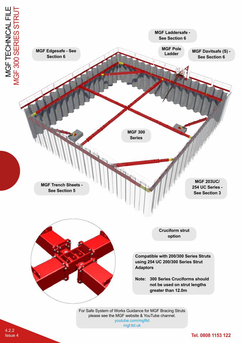
MGF 300 Series
Cruciform strut option
Compatible with 200/300 Series Struts using 254 UC 200/300 Series Strut Adaptors Note: 300 Series Cruciforms should not be used on strut lengths greater than 12.0m
For Safe System of Works Guidance for MGF Bracing Struts please see the MGF website & YouTube channel.
Strut assemblies are lifted and handled by attaching MGF lifting chains to the handling/restraining
points as shown.
Top Swivel Bearing Detail The swivel is secured to the UC section by bolting RSA sections to the swivel base plate using 12 No. grade 8.8 M20 bolts c/w nuts
and washers.
Base Swivel Bearing Detail The swivel can be secured
to the floor slab using anchor bolts.
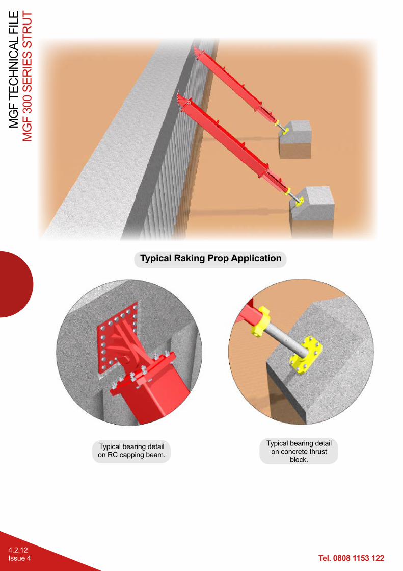
Vertical Shear Restraint Detail The vertical restraint detail should be used whenever there is a raking prop. It can either be welded to the pan of
sheets or bolted to a concrete wall using anchors.
Strut Flange Connection Detail300 Series Strut assemblies and swivel plates are connected to 300 Series Extensions using a transition plate (400x400x20mm), 8 No. grade 8.8 M20 countersunk bolts and 8 No. grade 8.8 M20 bolts, c/w nuts and washers.
300 Series Extensions are connected to each other via a flange plate (400x400x20mm) using 8 No. grade 8.8 M20 bolts c/w nuts and washers
(recommended min. torque 300Nm).
Tel. 0808 1153 122
MG
F TE
CH
NIC
AL F
ILE
MG
F 30
0 SE
RIE
S ST
RU
T
4.2.4Issue 4
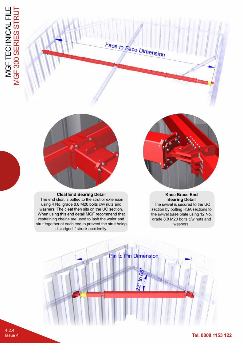
Cleat End Bearing Detail The end cleat is bolted to the strut or extension using 4 No. grade 8.8 M20 bolts c/w nuts and
washers. The cleat then sits on the UC section. When using this end detail MGF recommend that restraining chains are used to lash the waler and
strut together at each end to prevent the strut being dislodged if struck accidently.
Knee Brace End Bearing Detail
The swivel is secured to the UC section by bolting RSA sections to the swivel base plate using 12 No. grade 8.8 M20 bolts c/w nuts and
Material Grade ST52 S355Screw Thread Detail Φ100, 24 pitch
Unit Mass 27.0kg/m 50.8kg/mAxial SWL 540kN 540kN
Moment SWL 22kNm 100kNm
Tel. 0808 1153 122
MG
F TE
CH
NIC
AL F
ILE
MG
F 30
0 SE
RIE
S ST
RU
T
4.2.8Issue 4
600kN Double Acting Hydraulic Ram Assembly
Hydraulic Cylinder Double ActingMaterial Steel
Bore 140mmMax .Working Pressure 390 Bar (5700 psi)
Test Pressure 390 Bar (5700 psi)Approx. Working Stroke 600mm
Axial SWL 600kNMin. FOS (by test) 2
Working Temp Range -20ºC* to +50ºCApprox. Pre-Load 150kN
Approx. Pre-Load Pressure 100 Bar (1500 psi)Locating Pins Φ22 and Φ26mm
* Winter mix required for shoring fluid at low temps.
Shoring fluid is pumped into the full bore side of the piston through the male quick release valve (QRV) to extend the ram.At the same time fluid from the return side of the piston is returned to the pump via the female QRV. Retraction is a reverse of extension.Ensure isolation valve is closed to maintain pre-load pressure and before release/connection of QRV’s.
Pump UnitsThe pumps are used to extend and retract the 300 Series double acting hydraulic rams. The pumps contain bio-degradable Houghto Safe SF25 shoring fluid. During the Summer months the shoring fluid is diluted with water at a ratio of 3 parts water to 1 part Houghto Safe SF25. In the Winter the mix ratio is 1:1.Maximum recommended installation pressure 1500 psi (100 Bar).There are 2 types of pumps available, a manually operated bucket pump and a motorised petrol pump.
Bucket Pump Petrol Motorised PumpProduct ID 1.603 (DA) 8.4007
N.B Single 0.5m extensions should be added to these combinations for intermediate dimensions. The strut assemblies are shown at mid-stroke, so each length can vary by up to 372mm in either direction.